EP2922491B1 - Verfahren zur planung einer dentalen behandlung - Google Patents
Verfahren zur planung einer dentalen behandlung Download PDFInfo
- Publication number
- EP2922491B1 EP2922491B1 EP13810900.4A EP13810900A EP2922491B1 EP 2922491 B1 EP2922491 B1 EP 2922491B1 EP 13810900 A EP13810900 A EP 13810900A EP 2922491 B1 EP2922491 B1 EP 2922491B1
- Authority
- EP
- European Patent Office
- Prior art keywords
- planning
- patient model
- patient
- video recording
- video camera
- Prior art date
- Legal status (The legal status is an assumption and is not a legal conclusion. Google has not performed a legal analysis and makes no representation as to the accuracy of the status listed.)
- Active
Links
Images

Classifications
-
- H—ELECTRICITY
- H04—ELECTRIC COMMUNICATION TECHNIQUE
- H04N—PICTORIAL COMMUNICATION, e.g. TELEVISION
- H04N7/00—Television systems
- H04N7/18—Closed-circuit television [CCTV] systems, i.e. systems in which the video signal is not broadcast
-
- A—HUMAN NECESSITIES
- A61—MEDICAL OR VETERINARY SCIENCE; HYGIENE
- A61C—DENTISTRY; APPARATUS OR METHODS FOR ORAL OR DENTAL HYGIENE
- A61C9/00—Impression cups, i.e. impression trays; Impression methods
- A61C9/004—Means or methods for taking digitized impressions
- A61C9/0046—Data acquisition means or methods
-
- G—PHYSICS
- G01—MEASURING; TESTING
- G01B—MEASURING LENGTH, THICKNESS OR SIMILAR LINEAR DIMENSIONS; MEASURING ANGLES; MEASURING AREAS; MEASURING IRREGULARITIES OF SURFACES OR CONTOURS
- G01B11/00—Measuring arrangements characterised by the use of optical techniques
- G01B11/24—Measuring arrangements characterised by the use of optical techniques for measuring contours or curvatures
- G01B11/25—Measuring arrangements characterised by the use of optical techniques for measuring contours or curvatures by projecting a pattern, e.g. one or more lines, moiré fringes on the object
- G01B11/254—Projection of a pattern, viewing through a pattern, e.g. moiré
-
- G—PHYSICS
- G06—COMPUTING OR CALCULATING; COUNTING
- G06T—IMAGE DATA PROCESSING OR GENERATION, IN GENERAL
- G06T7/00—Image analysis
- G06T7/0002—Inspection of images, e.g. flaw detection
- G06T7/0012—Biomedical image inspection
-
- H—ELECTRICITY
- H04—ELECTRIC COMMUNICATION TECHNIQUE
- H04N—PICTORIAL COMMUNICATION, e.g. TELEVISION
- H04N13/00—Stereoscopic video systems; Multi-view video systems; Details thereof
- H04N13/20—Image signal generators
-
- H—ELECTRICITY
- H04—ELECTRIC COMMUNICATION TECHNIQUE
- H04N—PICTORIAL COMMUNICATION, e.g. TELEVISION
- H04N5/00—Details of television systems
- H04N5/222—Studio circuitry; Studio devices; Studio equipment
- H04N5/262—Studio circuits, e.g. for mixing, switching-over, change of character of image, other special effects ; Cameras specially adapted for the electronic generation of special effects
- H04N5/265—Mixing
Definitions
- the invention relates to a method for planning a dental treatment, wherein a video recording of an object to be treated is recorded by means of at least one video camera.
- planning is carried out directly on the patient, with the attending physician examining the patient's dental situation for diseased areas and subsequently recording possible treatments and comments on the individual tooth areas.
- accurate planning of the dimensions, orientations and positions of the dental prosthesis or implants is usually carried out subsequently to a model of the dental situation.
- the planning of the tooth replacement parts or implants to be used can also be carried out on the basis of three-dimensional X-ray data which can be superimposed on the optical three-dimensional surface data of the tooth situation.
- the planning can be purely virtual, without having to make a real impression model of the dental situation.
- US 2004/0197727 A1 discloses a method and workstation for planning orthodontic treatment of a patient.
- the workstation has a computer and a graphical user interface, wherein 3D image data of the patient by means of the graphical user interface. It can also simulate the insertion of dental prostheses and other dental treatments.
- 3D image data may be superimposed.
- the virtual patient model can not only represent facial surfaces of the patient but also internal structures such as tooth roots, jawbones.
- Conventional CAD software tools can be used to view this virtual patient model.
- the virtual patient model can be viewed from any direction or even only sectional views can be displayed in defined levels.
- characteristic matching points for example on the 3D x-ray of the jaw and in the three-dimensional optical image of the facial surfaces, can be used to calculate a transformation matrix.
- a disadvantage of the methods mentioned is that the planning takes place consuming in several steps, wherein first volume data sets of the dental situation, such as three-dimensional X-ray data and / or optical surface data, are generated and only then the planning by means of planning software based on these volume data sets.
- the document US2004 / 0029068 also discloses a method for planning or reviewing the planning of a dental procedure.
- the object of the present invention is therefore to provide a method for planning a dental treatment, which allows a simple, fast and better planning.
- the invention relates to a method for planning or checking the planning of a dental and / or a maxillofacial treatment, wherein a video recording of an object, such as from the head of a patient to be treated, is recorded by means of at least one video camera.
- a video recording of an object such as from the head of a patient to be treated
- the video recording is virtually coupled to the patient model so that when moving the video camera relative to the object, a viewing direction of the view is changed to the patient model depending on a changing recording direction of the video recording.
- a section of the patient model to be displayed is defined by a distance of the video camera relative to the object and by a recording direction of the video camera relative to the object.
- the dental treatment to be planned may include, for example, the analysis of the dental situation on diseased areas and the determination of possible therapies.
- the treatment options can be, for example, preparations to be made, dental restoration parts to be applied to preparations or implants to be inserted.
- the video recording can be recorded, for example, with an image response rate of 50 Hz.
- the object to be recorded may be, for example, a lower jaw, an upper jaw, a group of teeth and / or the entire head of a patient.
- the object to be photographed may alternatively be an impression model of the tooth situation on which the planning is carried out.
- the already existing patient model comprises recorded image data, such as three-dimensional optical image data, three-dimensional x-ray data and / or MRI image data.
- the video recording of the object is linked to the existing one Patient model coupled so that the virtual line of view of the view on the patient model of the recording direction of the video camera follows.
- the viewing direction of the representation of the patient model coincides with the recording direction of the video camera.
- the patient model can, in addition to the image data, also include further information on the tooth situation, such as the bone density of the jawbone, in order, for example, to carry out a mechanical stress simulation in implant planning.
- the treating dentist can thus direct the video camera to a specific region of the head, wherein the patient model is displayed for example by means of a monitor from the corresponding line of sight.
- the dentist can also approach the video camera closer to a specific area, wherein only the corresponding section of the three-dimensional x-ray image data of the patient model is displayed.
- the patient model may comprise three-dimensional optical surface data, three-dimensional x-ray data, virtual planning data and / or MRT image data of at least a part of the object.
- the three-dimensional optical surface data may be generated, for example, by a fringe projection method.
- the three-dimensional X-ray data can be generated for example by a DVT measurement method or a computed tomography (CT) method.
- CT computed tomography
- the image data of the patient model can also include only a part of the object. For example, if the subject is the entire head of the patient, the X-ray data can only be the maxilla or the lower jaw.
- the patient model can also contain X-ray data of a two-dimensional cephalometric X-ray or panoramic image.
- the virtual planning data can, for example, comprise planning elements, such as virtual markings, comments, simple drawings or models of tooth replacement parts and / or implants to be inserted, which have a fixed positional relationship to the surrounding tooth situation consisting of teeth and gums.
- the video recording can be displayed in superposition with the patient model by means of at least one display device, such as a monitor.
- the video recording can, for example, be displayed in a semi-transparent manner, with the patient model being displayed. This allows the treating dentist easier orientation relative to the patient.
- the patient model may be displayed by the monitor alone, with the video only being used to determine the direction of taking.
- the display device may be a virtual monitor goggle, with navigation relative to the patient model in virtual reality being accomplished by movement of the goggle goggles relative to the patient.
- augmented reality virtual reality display devices may also be used.
- the display device may be a so-called tablet computer or a portable personal digital assistant (PDA) computer, wherein the video recording is generated by means of the video camera integrated in the tablet computer or in the portable PDA computer is.
- the patent model is then displayed in accordance with the movement of the tablet computer or the portable PDA computer from the respective viewing direction by means of the monitor of the tablet computer or the portable PDA computer.
- PDA personal digital assistant
- the virtual coupling of the video recording to the patient model can be done using pattern recognition algorithms.
- markings which are attached to the object, or characteristic structures of the object, such as the eyes, nose, mouth or teeth of the patient can be recognized both in the video recording and in the patient model in order to establish an association between the video recording and the patient model.
- matching areas in the video and patient models are determined and used to determine the orientation of the video and patient models.
- the matching areas may be, for example, characteristic shape courses, such as the chin of the patient or the two angles of the jawbone.
- markers may be applied directly to the object, for example, optical markers may be applied directly to the skin in the cheek area of the patient. These markers are then recognized both in the video recording and in the patient model and used to determine the orientation of the video recording relative to the patient model and to determine the recording direction of the video camera relative to the object.
- the recognition of the markings can be done fully automatically by means of a computer algorithm, which searches the video recording for a specific pattern of the markings.
- the coupling of the video recording The patient model can also be performed prior to the execution of the planning during an initial registration, wherein the recordings of the markers in the video recording can be manually assigned to the recordings of the markers in the patient model.
- the coupling between the video recording and the patient model can also be done manually by a user, defining corresponding points in the video recording and in the patient model.
- the determination of the changing recording direction of the video camera relative to the object automatically computer-aided by tracking the attached to the object markers or characteristic structures of the object, such as eyes, nose, mouth or teeth of the patient done.
- the determination of the changing recording direction of the video camera thus takes place by means of a tracking method in which the position of the markings or of the characteristic structures in the video recording is tracked.
- the corresponding viewing direction is then calculated on the patient model and the corresponding section of the patient model is displayed from the calculating viewing direction by means of a monitor.
- the planning can take place directly during the video recording, wherein planning elements are displayed in superimposition with the patient model by means of a display device and thereby the user determines their position relative to the patient model.
- the planning elements can be markings, comments, simple drawings or models of dental prostheses or implants to be inserted, whose position is determined relative to the patient model.
- the attending dentist may add markers to certain areas of the dental situation to be treated and annotate them with a diagnosis.
- the markers may be simple ink strokes or pre-made symbols provided by software.
- the comments can be free texts which are indicated by means of a keyboard at a position defined by means of a mouse.
- the planning elements can be projected directly onto the object to be treated by means of a projector.
- the projector may be a conventional optical projector that projects the planning elements directly onto the skin surface or teeth of the patient.
- the planning can be carried out directly on the patient, so that no display device for displaying the planning elements is necessary.
- the planning can be done by means of a marker, wherein an optical pointer is projected onto the patient, which is detected during the video recording by means of the video camera.
- the optical pointer serves as a virtual tool for selecting and moving the scheduling elements within the patient model projected onto the patient. This allows the individual planning elements, such as comments or markers, to be added and moved using the optical marker. The position of the planning elements is determined relative to the patient model.
- the optical marker may be a laser pointer projecting a laser spot onto the object.
- the treating dentist can also carry out planning from a greater distance.
- the laser dot is color-coordinated so that it can be clearly recognized in the video recording.
- the planning can take place by means of an optically detectable marker, which is detected during the video recording by means of the video camera.
- the optically detectable marker may be a pencil with a colored tip, a finger or a dental instrument.
- the planning elements projected onto the object can be selected and moved by means of the marker in order to determine their position relative to the patient model.
- the treating dentist can use the marker to select the individual planning elements, such as markings, comments, drawings or models of tooth replacement parts or implants to be inserted, and move them relative to the patient model in order to determine their position.
- the selection of one of the planning elements can take place in that the user actuates a switch on the marker and thereby a specific structure is projected onto the surface of the object to be treated, this structure being recognizable in the video recording.
- the switch on the marker can be configured as desired and executed, for example, as a key.
- the structure is projected onto the object, which may be embodied, for example, as a particular overlaid pattern, a color change of the optical mark, a shape change of the optical mark, or a dummy code.
- an action such as the selection of a particular planning element, is triggered.
- the relevant planning element can then be moved.
- the key is released, the planning element is then released from the optical marking, thereby determining the position of this planning element relative to the patient model.
- the image data and / or the virtual planning data of the patient model can be projected onto the object to be treated by means of a projector in order to facilitate planning.
- the patient model can be projected onto the skin surface of the patient by means of the projector.
- X-rays of a Jaw bone structure are projected onto the relevant area of the skin surface to facilitate orientation for the treating dentist.
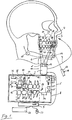
- the Fig. 1 shows a sketch to illustrate the method for planning a dental treatment.
- a video camera 1 which is arranged on a handpiece 2
- a video recording of an object 3 to be treated is recorded.
- the object 3 in this case is the head of a patient.
- the video recording thus absorbs the skin surface in the cheek area of the head 3.
- An already existing patient model 4 comprises already recorded image data of the object 3, as shown in the present case, for example, three-dimensional X-ray data of the object 3.
- the patient model 4 can also have further image data, such as three-dimensional optical image data and / or MRT image data of the object 3.
- the image data of the patient model are stored in an image memory of a computer 5.
- the image data of the video recording are transmitted from the video camera 1 to the computer 5 via a cable connection 6.
- the image data of the video camera 1 can also be transmitted wirelessly to a computer 5.
- the video recording of the object 3 is virtually coupled to the patient model 4, that when moving the video camera 1 about the object 3 along a movement path 7, the representation of the patient model 4 is adjusted by means of a monitor 8 to a changing recording direction 9 of the video camera 1.
- the video camera 1 picks up a first section 10 of the skin surface of the object 3.
- markings 11 which are attached to the object 3 can be recognized. Based on the positioning of the markers 11, the exact position of the object 3 relative to the video camera 1 is then calculated.
- a second section 12 of the patient model 4 is shown by means of the monitor 8, which corresponds in its dimensions to the first section 10 from the video recording.
- the treating dentist can move the video camera 1 around the patient 3 at will and focus on the relevant areas.
- the monitor 8 then automatically displays the corresponding section 12 of the corresponding patient data, such as the x-ray data, from a viewing direction which corresponds, for example, to the recording direction of the video camera.
- An initial registration can be carried out before the planning, in which the recordings of the markers 11 in the video recording are assigned to the corresponding recordings of the markers 11 in the patient model 4, as in the present case in the x-ray data.
- the markings 11 in addition to the visual recognizability must also be X-ray sensitive.
- the registration or the matching between the video recording and the patient model 4 can alternatively also be object-based without markings.
- the registration is performed by the assignment or superimposition of characteristic anatomical structures, such as the eyes, the nose and / or the mouth of the patient, in the video recording and in the patient model 4.
- This assignment can be done manually by a user or automatically by pattern recognition algorithms.
- the position of the markers 11 in the video recording is followed by means of a tracking method, so that the viewing direction 13 is automatically moved to the patient model as a function of the recording direction 9.
- the tracking of the direction of picking relative to the object 3 can also take place without markings 11 using marked areas of the object 3, such as the chin 14 and / or the jawbone angle 15. These characteristic areas of the object 3 can be detected computer-assisted in the video recording by means of a pattern recognition algorithm.
- a pattern recognition algorithm Alternatively to the representation of the patient model 4 by means of the monitor 8, at least a part of the patient model can be projected onto the skin surface of the object 3 by means of a projector 16, which can be integrated in the handpiece 2. This makes it easier for the treating dentist to plan the dental treatment since the X-ray data of the patient model 4 are displayed directly on the skin surface.
- the planning can then be performed by means of an optical marker 17, such as a laser pointer, directly on the skin surface of the patient.
- the laser pointer 17 projects a laser spot 18 serving as a cursor onto the skin surface.
- a particular texture such as a pattern or blink code, is projected onto the skin surface.
- a particular planning element 20 such as a commentary 21, a marker 22, a model of an implant 23, a model of a dental prosthesis 24 or a model of an abutment 25 can be selected and inserted into the illustrated patient model 4.
- the selected planning element 20 can be moved and positioned at a certain position relative to the patient model 4.
- the respective planning element 20 is then released from the laser point 18, thereby defining the position of the planning element 20.
- the selection and insertion of the scheduling elements 20 into the patient model 4 using input means, such as a keyboard 26 and a mouse 27, may be performed on the monitor 8 via a cursor 28.
- a first finding 29 of a caries-affected tooth may be provided with a mark 30 by means of the marking tool 22 and with a comment 31 in textual form.
- the comment 31 may be entered by the user by means of the keyboard 26 and may include, for example, information on the finding and the position of the tooth in question.
- a second finding 32 of a laterally affected tooth can be provided with a mark 23 and a comment 34 accordingly.
- a region 35 with the missing tooth can be provided with a further comment 36, wherein subsequently an implant 37 to be inserted, an abutment 38 to be inserted and a tooth replacement part 39 to be inserted are planned.
- the corresponding models 23, 24 and 25 are adapted in their dimensions and orientations to the tooth situation.
- the advantage of this method is therefore that the analysis of the findings and the planning of a treatment can take place immediately during the video recording. This shortens the treatment time and facilitates the orientation for the treating dentist.
- the planning elements 20 can also be projected onto the skin surface 3 by means of the projector 16 as an alternative or in addition to the representation by means of the monitor 8.
- the Fig. 2 shows a sketch to illustrate the video recording from different shooting directions.
- the video camera 1 is moved around the object 3 and thereby positioned at a first position 40, at a second position 41, at a third position 42, at a fourth position 43 and at a fifth position 45.
- the video camera 1 generates the video recording from a first recording direction 46, from a second recording direction 47, from a third recording direction 48, from a fourth recording direction 49 and from a fifth recording direction 50 of the object 3.
- a first section 10, a second section 51, a third cutout 52, a fourth cutout 53 and a fifth cutout 54 of the skin surface of the patient 3 are taken.
- the positioning of the video camera 1 relative to the patient 3 can then be determined on the basis of the markings 11 arranged on the patient 3. Then, as in Fig. 1 explains, the appropriate section of the patient model 4, as well as the X-ray data, displayed by means of the monitor 8.
- a first cutout 55, at the second position 41 a second cutout 56, at the third position 42 a third cutout 57, at the fourth position 43 a fourth cutout 58 and at the fifth Position 45 a fifth section 59 of the patient model 4 is displayed.
Landscapes
- Engineering & Computer Science (AREA)
- Health & Medical Sciences (AREA)
- Multimedia (AREA)
- Signal Processing (AREA)
- General Health & Medical Sciences (AREA)
- Computer Vision & Pattern Recognition (AREA)
- Physics & Mathematics (AREA)
- General Physics & Mathematics (AREA)
- Life Sciences & Earth Sciences (AREA)
- Epidemiology (AREA)
- Dentistry (AREA)
- Animal Behavior & Ethology (AREA)
- Oral & Maxillofacial Surgery (AREA)
- Public Health (AREA)
- Veterinary Medicine (AREA)
- Medical Informatics (AREA)
- Nuclear Medicine, Radiotherapy & Molecular Imaging (AREA)
- Radiology & Medical Imaging (AREA)
- Quality & Reliability (AREA)
- Theoretical Computer Science (AREA)
- Apparatus For Radiation Diagnosis (AREA)
- Dental Tools And Instruments Or Auxiliary Dental Instruments (AREA)
Description
- Die Erfindung betrifft ein Verfahren zur Planung einer dentalen Behandlung, wobei mittels mindestens einer Videokamera eine Videoaufnahme von einem zu behandelnden Objekt aufgenommen wird.
- Aus dem Stand der Technik sind mehrere Verfahren zur Planung von dentalen Behandlungen bekannt.
- Bei einem ersten bekannten Verfahren erfolgt die Planung unmittelbar am Patienten, wobei der behandelnde Arzt die Zahnsituation des Patienten auf erkrankte Bereiche hin untersucht und anschließend mögliche Behandlungen sowie Kommentare zu den einzelnen Zahnbereichen notiert. Bei einzusetzenden Zahnersatzteilen oder Implantaten wird meist anschließend an einem Modell der Zahnsituation eine genaue Planung der Abmessungen, Ausrichtungen sowie Positionen der Zahnersatzteile oder Implantate durchgeführt.
- Alternativ dazu kann die Planung der einzusetzenden Zahnersatzteile oder Implantate auch anhand von dreidimensionalen Röntgendaten erfolgen, die mit optischen dreidimensionalen Oberflächendaten der Zahnsituation überlagert sein können. Dadurch kann die Planung rein virtuell erfolgen, ohne ein reales Abdruckmodell der Zahnsituation anfertigen zu müssen.
-
US 2004/0197727 A1 offenbart ein Verfahren und eine Arbeitsstation zur Planung einer orthodontischen Behandlung eines Patienten. Die Arbeitsstation weist dabei einen Computer und eine graphische Benutzeroberfläche auf, wobei 3D-bilddaten des Patienten mittels der graphischen Benutzeroberfläche angezeigt werden. Dabei kann auch das Einsetzen von Zahnersatzteilen sowie andere zahnärztliche Behandlungen simuliert werden. Zur Erzeugung eines virtuellen Patientenmodells können mehrere Arten von 3D-Bilddaten, wie optische Intraoralaufnahmen, Röntgendaten, CT-Aufnahmen, intraorale farbliche Fotografien der Zähne und auch virtuelle 3D-Zahnmodelle, in Überlagerung gebracht werden. Das virtuelle Patientenmodell kann damit nicht nur Gesichtsoberflächen des Patienten sondern auch interne Strukturen, wie Zahnwurzeln, Kieferknochen, darstellen. Zum Betrachten dieses virtuellen Patientenmodells können herkömmliche CAD-Softwarewerkzeuge verwendet werden. Dabei kann das virtuelle Patientenmodell aus jeder Richtung betrachtet werden oder auch nur Schnittansichten in definierten Ebenen angezeigt werden. Zum Ausrichten der einzelnen 3D-Datensätze zueinander können charakteristische übereinstimmende Punkte, beispielsweise auf der 3D-Röntgenaufnahme des Kiefers und in der dreidimensionalen optischen Aufnahme der Gesichtsoberflächen, verwendet werden, um eine Transformationsmatrix zu berechnen. - Ein Nachteil der genannten Verfahren besteht darin, dass die Planung aufwendig in mehreren Schritten erfolgt, wobei zunächst Volumendatensätze der Zahnsituation, wie dreidimensionale Röntgendaten und/oder optische Oberflächendaten, erzeugt werden und erst anschließend die Planung mittels einer Planungssoftware anhand dieser Volumendatensätze erfolgt. Das Dokument
US2004/0029068 offenbart auch ein Verfahren zur Planung oder Überprüfung der Planung einer dentalen Behandlung. - Die Aufgabe der vorliegenden Erfindung besteht daher darin, ein Verfahren zur Planung einer dentalen Behandlung bereitzustellen, das eine einfache, schnelle und bessere Planung ermöglicht.
- Die Erfindung betrifft ein Verfahren zur Planung oder zur Überprüfung der Planung einer dentalen und/oder einer maxillofazialen Behandlung, wobei mittels mindestens einer Videokamera eine Videoaufnahme von einem Objekt, wie vom Kopf eines zu behandelnden Patienten, aufgenommen wird. Dabei ist ein Patientenmodell vorhanden, das Bilddaten des Objekts umfasst. Die Videoaufnahme wird virtuell an das Patientenmodell so gekoppelt, dass beim Bewegen der Videokamera relativ zum Objekt eine Blickrichtung der Ansicht auf das Patientenmodell abhängig von einer sich ändernden Aufnahmerichtung der Videoaufnahme verändert wird. Ein darzustellender Ausschnitt des Patientenmodells wird dabei durch einen Abstand der Videokamera relativ zum Objekt und durch eine Aufnahmerichtung der Videokamera relativ zum Objekt definiert.
- Die zu planende dentale Behandlung kann beispielsweise die Analyse der Zahnsituation auf erkrankte Bereiche und die Bestimmung möglicher Therapien umfassen. Die Therapiemöglichkeiten können beispielsweise durchzuführende Präparationen, auf Präparationen aufzusetzende Zahnersatzteile oder einzusetzende Implantate sein. Die Videoaufnahme kann beispielsweise mit einer Bildwiderholungsrate von 50 Hz aufgenommen werden. Das aufzunehmende Objekt kann beispielsweise ein Unterkiefer, ein Oberkiefer, eine Gruppe von Zähnen und/oder der gesamte Kopf eines Patienten sein. Das aufzunehmende Objekt kann jedoch auch alternativ ein Abdruckmodell der Zahnsituation sein, an dem die Planung durchgeführt wird. Das bereits vorhandene Patientenmodell umfasst aufgenommene Bilddaten, wie dreidimensionale optische Bilddaten, dreidimensionale Röntgendaten und/oder MRT-Bilddaten. Die Videoaufnahme des Objekts wird an das vorhandene Patientenmodell gekoppelt, so dass die virtuelle Blickrichtung der Ansicht auf das Patientenmodell der Aufnahmerichtung der Videokamera folgt. Die Blickrichtung der Darstellung des Patientenmodells stimmt mit der Aufnahmerichtung der Videokamera überein. Das Patientenmodell kann zusätzlich zu dem Bilddaten auch weitere Informationen zu der Zahnsituation, wie die Knochendichte des Kieferknochen, umfassen, um beispielsweise eine mechanische Belastungssimulation bei einer Implantatplanung durchzuführen.
- Dadurch kann der behandelnde Zahnarzt also die Videokamera auf eine bestimmte Region des Kopfes richten, wobei das Patientenmodell beispielsweise mittels eines Monitors aus der entsprechenden Blickrichtung dargestellt wird. Dies erleichtert dem Zahnarzt erheblich die Orientierung und die Planung der dentalen Behandlung. Der Zahnarzt kann mit der Videokamera auch näher an einen bestimmten Bereich herangehen, wobei lediglich der entsprechende Ausschnitt aus den dreidimensionalen Röntgenbilddaten des Patientenmodells dargestellt wird.
- Vorteilhafterweise kann das Patientenmodell dreidimensionale optische Oberflächendaten, dreidimensionale Röntgendaten, virtuelle Planungsdaten und/oder MRT-Bilddaten zumindest eines Teils des Objekts umfassen.
- Die dreidimensionalen optischen Oberflächendaten können beispielsweise durch ein Streifenprojektionsverfahren erzeugt werden. Die dreidimensionalen Röntgendaten können beispielsweise durch ein DVT-Messverfahren oder ein Computertomographieverfahren (CT) erzeugt werden. Die Bilddaten des Patientenmodells können auch nur einen Teil des Objekts umfassen. Falls das Objekt der gesamte Kopf des Patienten ist, können die Röntgendaten beispielsweise nur den Oberkiefer oder den Unterkiefer enthalten. Das Patientenmodell kann auch Röntgendaten einer zweidimensionalen cephalometrischen Röntgenaufnahme oder einer Panoramaaufnahme enthalten. Die virtuellen Planungsdaten können beispielsweise Planungselemente, wie virtuelle Markierungen, Kommentare, einfache Zeichnungen oder Modelle von einzusetzenden Zahnersatzteilen und/oder Implantaten, umfassen, die eine feste Lagebeziehung zu der umgebenden Zahnsituation, bestehend aus Zähnen und Zahnfleisch, aufweisen.
- Vorteilhafterweise kann die Videoaufnahme in Überlagerung mit dem Patientenmodell mittels mindestens einer Anzeigevorrichtung, wie eines Monitors, angezeigt werden.
- Die Videoaufnahme kann beispielsweise halbtransparent dargestellt werden, wobei das Patientenmodell eingeblendet wird. Dies ermöglicht dem behandelnden Zahnarzt eine einfachere Orientierung relativ zum Patienten. Alternativ dazu kann das Patientenmodell allein mittels des Monitors angezeigt werden, wobei die Videoaufnahme lediglich zur Bestimmung der Aufnahmerichtung verwendet wird.
- Alternativ kann die Anzeigevorrichtung eine virtuelle Monitor-Brille sein, wobei das Navigieren relativ zum Patientenmodell in der virtuellen Realität durch die Bewegung der Monitor-Brille relativ zum Patienten erfolgt.
- Als Anzeigevorrichtung können auch andere anzeigende oder einblendende(engl.: augmented reality) Virtual-Reality-Anzeigevorrichtungen verwendet werden.
- Bei einer weiteren Alternative kann die Anzeigevorrichtung ein sogenannter Tablet-Computer oder ein portabler PDA-Computer (Personal Digital Assistant) sein, wobei die Videoaufnahme mittels der Videokamera erzeugt wird, die in den Tablet-Computer oder in den portablen PDA-Computer integriert ist. Das Patentmodell wird dann abhängig von der Bewegung des Tablet-Computers oder des portablen PDA-Computers aus der entsprechenden Blickrichtung mittels des Monitors des Tablet-Computers oder des portablen PDA-Computers angezeigt.
- Vorteilhafterweise kann die virtuelle Kopplung der Videoaufnahme an das Patientenmodell unter Verwendung von Mustererkennungsalgorithmen erfolgen. Dabei können Markierungen, die am Objekt angebracht werden, oder charakteristische Strukturen des Objekts, wie Augen, Nase, Mund oder Zähne des Patienten, sowohl in der Videoaufnahme als auch im Patientenmodell erkannt werden, um eine Zuordnung zwischen der Videoaufnahme und dem Patientenmodell herzustellen.
- Bei der Verwendung von Mustererkennungsalgorithmen werden übereinstimmende Bereiche in der Videoaufnahme und im Patientenmodell ermittelt und zur Bestimmung der Orientierung der Videoaufnahme und des Patientenmodells zueinander verwendet. Die übereinstimmenden Bereiche können beispielsweise charakteristische Formverläufe, wie das Kinn des Patienten oder die beiden Winkel des Kieferknochens sein.
- Alternativ dazu können Markierungen direkt am Objekt angebracht werden, beispielsweise können optische Markierungen direkt auf der Haut im Wangenbereich des Patienten angebracht werden. Diese Markierungen werden dann sowohl in der Videoaufnahme als auch im Patientenmodell erkannt und zur Ermittlung der Orientierung der Videoaufnahme relativ zum Patientenmodell und zur Ermittlung der Aufnahmerichtung der Videokamera relativ zum Objekt verwendet. Die Erkennung der Markierungen kann vollautomatisch mittels eines Computeralgorithmus erfolgen, der die Videoaufnahme auf ein bestimmtes Muster der Markierungen absucht. Die Kopplung der Videoaufnahme an das Patientenmodell kann auch vor der Durchführung der Planung bei einer Erstregistrierung durchgeführt werden, wobei die Aufnahmen der Markierungen in der Videoaufnahme manuell den Aufnahmen der Markierungen im Patientenmodell zugeordnet werden können.
- Die Kopplung zwischen der Videoaufnahme und dem Patientenmodell kann auch manuell durch einen Benutzer erfolgen, wobei übereinstimmende Punkte in der Videoaufnahme und in Patientenmodell definiert werden.
- Vorteilhafterweise kann die Bestimmung der sich ändernden Aufnahmerichtung der Videokamera relativ zum Objekt automatisch computergestützt durch Verfolgung der am Objekt angebrachten Markierungen oder von charakteristischen Strukturen des Objekts, wie Augen, Nase, Mund oder Zähne des Patienten, erfolgen.
- Die Bestimmung der sich ändernden Aufnahmerichtung der Videokamera erfolgt also durch ein Trackingverfahren, bei dem die Position der Markierungen oder der charakteristischen Strukturen in der Videoaufnahme verfolgt wird. Abhängig von der sich ändernden Aufnahmerichtung wird dann die entsprechende Blickrichtung auf das Patientenmodell berechnet und der entsprechende Ausschnitt des Patientenmodells aus der berechnenden Blickrichtung mittels eines Monitors dargestellt.
- Vorteilhafterweise kann die Planung unmittelbar während der Videoaufnahme erfolgen, wobei Planungselemente in Überlagerung mit dem Patientenmodell mittels einer Anzeigevorrichtung angezeigt werden und dabei durch den Benutzer deren Position relativ zum Patientenmodell festgelegt wird.
- Dadurch kann der behandelnde Zahnarzt dem Patientenmodell Planungselemente, wie Markierungen, Kommentare, Zeichnungen oder Modelle von Zahnersatzteilen bzw. Implantaten, hinzufügen und deren Position in der Zahnsituation festlegen. Dies erfolgt simultan zur Videoaufnahme unmittelbar am Patienten, so dass dadurch die Behandlungszeit verkürzt wird und mögliche Fehler auch während der Planung vermieden werden.
- Vorteilhafterweise können die Planungselemente Markierungen, Kommentare, einfache Zeichnungen oder Modelle von einzusetzenden Zahnersatzteilen bzw. Implantaten sein, deren Position relativ zum Patientenmodell festgelegt wird.
- Der behandelnde Zahnarzt kann beispielsweise Markierungen an bestimmten zu behandelnden Bereichen der Zahnsituation hinzufügen und diese mit Kommentaren versehen, die eine Diagnose enthalten. Die Markierungen können einfache Freihandstriche oder vorgefertigte Symbole sein, die von einer Software bereitgestellt werden. Die Kommentare können Freitexte sein, die mittels einer Tastatur an einer mittels einer Maus definierten Position angegeben werden. Dadurch werden die Positionen der Planungselemente relativ zum Patientenmodell festgelegt, so dass die Planungselemente zusammen mit dem Patientenmodell mitgedreht werden, wenn sich die Blickrichtung auf das Patientenmodell ändert.
- Vorteilhafterweise können die Planungselemente direkt auf das zu behandelnde Objekt mittels eines Projektors projiziert werden.
- Der Projektor kann ein herkömmlicher optischer Projektor sein, der die Planungselemente direkt auf die Hautoberfläche oder die Zähne des Patienten projiziert. Dadurch kann die Planung unmittelbar am Patienten erfolgen, so dass keine Anzeigevorrichtung zum Darstellen der Planungselemente notwendig ist.
- Vorteilhafterweise kann die Planung mittels eines Markers erfolgen, wobei ein optischer Zeiger auf den Patienten projiziert wird, der während der Videoaufnahme mittels der Videokamera erfasst wird.
- Der optische Zeiger dient als ein virtuelles Werkzeug zum Auswählen und zum Verschieben der Planungselemente innerhalb des auf den Patienten projizierten Patientenmodells. Dadurch können die einzelnen Planungselemente, wie Kommentare oder Markierungen, mittels des optischen Markers hinzugefügt und verschoben werden. Dabei wird die Position der Planungselemente relativ zum Patientenmodell festgelegt.
- Vorteilhafterweise kann der optische Marker ein Laserpointer sein, der einen Laserpunkt auf das Objekt projiziert.
- Durch den Laserpointer als optischen Marker kann der behandelnde Zahnarzt die Planung auch aus einer größeren Distanz durchführen. Der Laserpunkt ist farblich so gestaltet, dass er in der Videoaufnahme eindeutig erkannt werden kann.
- Vorteilhafterweise kann die Planung mittels eines optisch erkennbaren Markers erfolgen, der während der Videoaufnahme mittels der Videokamera erfasst wird.
- Dadurch kann der behandelnde Zahnarzt mittels des Markers, wie eines Stiftes, navigieren und bestimmte Bereiche des Patientenmodells auswählen.
- Vorteilhafterweise kann der optisch erkennbare Marker ein Stift mit einer farblichen Spitze, ein Finger oder ein zahnärztliches Instrument sein.
- Vorteilhafterweise können die auf das Objekt projizierten Planungselemente mittels des Markers ausgewählt und verschoben werden, um deren Position relativ zum Patientenmodell festzulegen.
- Dadurch kann der behandelnde Zahnarzt mittels des Markers die einzelnen Planungselemente, wie Markierungen, Kommentare, Zeichnungen oder Modelle von einzusetzenden Zahnersatzteilen bzw. Implantaten, auswählen und relativ zum Patientenmodell verschieben, um deren Position festzulegen.
- Vorteilhafterweise kann die Auswahl eines der Planungselemente dadurch erfolgen, dass der Benutzer einen Schalter am Marker betätigt und dadurch eine bestimmte Struktur auf die Oberfläche des zu behandelnden Objekt projiziert wird, wobei diese Struktur in der Videoaufnahme erkennbar ist.
- Der Schalter am Marker kann beliebig ausgestaltet sein und beispielsweise als eine Taste ausgeführt sein. Beim Betätigen dieses Schalters wird die Struktur auf das Objekt projiziert, das beispielsweise als ein bestimmtes eingeblendetes Muster, eine Farbänderung der optischen Markierung, eine Formänderung der optischen Markierung oder als ein Blindcode ausgeführt sein kann. Auf das Drücken der Taste hin wird eine Aktion, wie beispielsweise die Auswahl eines bestimmten Planungselementes, ausgelöst. Solange die Taste gedrückt bleibt, kann dann das betreffende Planungselement verschoben werden. Beim Loslassen der Taste wird dann das Planungselement von der optischen Markierung losgelöst und dadurch die Position dieses Planungselements relativ zum Patientenmodell festgelegt.
- Vorteilhafterweise können zur Erleichterung der Planung die Bilddaten und/oder die virtuellen Planungsdaten des Patientenmodells mittels eines Projektors auf das zu behandelnde Objekt projiziert werden.
- Alternativ zur Darstellung des Patientenmodells mittels eines Monitors kann das Patientenmodell mittels des Projektors auf die Hautoberfläche des Patienten projiziert werden. Dadurch können beispielsweise Röntgenaufnahmen einer Kieferknochenstruktur auf den betreffenden Bereich der Hautoberfläche projiziert werden, um die Orientierung für den behandelnden Zahnarzt zu erleichtern.
- Die Erfindung wird anhand der Zeichnungen erläutert. Es zeigt, die
- Fig. 1
- eine Skizze zur Verdeutlichung des Verfahrens zur Planung einer dentalen Behandlung; die
- Fig. 2
- eine Skizze zur Verdeutlichung der Videoaufnahme aus verschiedenen Aufnahmerichtungen.
- Die
Fig. 1 zeigt eine Skizze zur Verdeutlichung des Verfahrens zur Planung einer dentalen Behandlung. Mittels einer Videokamera 1, die an einem Handstück 2 angeordnet ist, wird eine Videoaufnahme von einem zu behandelnden Objekt 3 aufgenommen. Das Objekt 3 ist in diesem Fall der Kopf eines Patienten. Die Videoaufnahme nimmt also die Hautoberfläche im Wangenbereich des Kopfes 3 auf. Ein bereits vorhandenes Patientenmodell 4 umfasst bereits aufgenommene Bilddaten des Objekts 3, wie beispielsweise im vorliegenden Fall dargestellt, dreidimensionale Röntgendaten des Objekts 3. Das Patientenmodell 4 kann auch weitere Bilddaten, wie dreidimensionale optische Bilddaten und/oder MRT-Bilddaten des Objekts 3, aufweisen. Die Bilddaten des Patientenmodells sind in einem Bildspeicher eines Computers 5 abgespeichert. Die Bilddaten der Videoaufnahme werden von der Videokamera 1 an den Computer 5 über eine Kabelverbindung 6 übermittelt. Die Bilddaten der Videokamera 1 können auch drahtlos an einen Computer 5 übermittelt werden. Die Videoaufnahme des Objekts 3 ist an das Patientenmodell 4 virtuell so gekoppelt, dass beim Bewegen der Videokamera 1 um das Objekt 3 entlang einer Bewegungsbahn 7 die Darstellung des Patientenmodells 4 mittels eines Monitors 8 an eine sich ändernde Aufnahmerichtung 9 der Videokamera 1 angepasst wird. Die Videokamera 1 nimmt einen ersten Ausschnitt 10 der Hautoberfläche des Objekts 3 auf. Bei der Auswertung der Bilddaten der Videoaufnahme mittels des Computers 5 können Markierungen 11, die am Objekt 3 angebracht sind, erkannt werden. Anhand der Positionierung der Markierungen 11 wird dann die genaue Lage des Objekts 3 relativ zur Videokamera 1 berechnet. Anschließend wird ein zweiter Ausschnitt 12 des Patientenmodells 4 mittels des Monitors 8 dargestellt, der in seinen Abmessungen dem ersten Ausschnitt 10 aus der Videoaufnahme entspricht. Dadurch kann der behandelnde Zahnarzt die Videokamera 1 beliebig um den Patienten 3 bewegen und auf die relevanten Bereiche richten. Der Monitor 8 zeigt daraufhin automatisch den entsprechenden Ausschnitt 12 der entsprechenden Patientendaten, wie der Röntgendaten, aus einer Blickrichtung, die beispielsweise der Aufnahmerichtung der Videokamera entspricht. Vor der Planung kann eine Erstregistrierung durchgeführt werden, bei der die Aufnahmen der Markierungen 11 in der Videoaufnahme den entsprechenden Aufnahmen der Markierungen 11 im Patientenmodell 4, wie im vorliegenden Fall in den Röntgendaten, zugeordnet werden. Dabei müssen die Markierungen 11 neben der optischen Erkennbarkeit auch röntgensensitiv sein. - Die Registrierung beziehungsweise das Matching zwischen der Videoaufnahme und den Patientenmodell 4 kann alternativ auch objektbasiert ohne Markierungen erfolgen. Dabei wird die Registrierung durch die Zuordnung bzw. Überlagerung charakteristischer anatomischer Strukturen, wie der Augen, der Nase und/oder des Mundes des Patienten, in der Videoaufnahme und im Patientenmodell 4 durchgeführt.
- Diese Zuordnung kann manuell durch einen Benutzer oder automatisch durch Mustererkennungsalgorithmen erfolgen. Nach der Erstregistrierung wird die Position der Markierungen 11 in der Videoaufnahme mittels eines Trackingverfahrens mitverfolgt, so dass die Blickrichtung 13 auf das Patientenmodell automatisch abhängig von der Aufnahmerichtung 9 mitbewegt wird.
- Die Mitverfolgung der Aufnahmerichtung relativ zum Objekt 3 kann auch ohne Markierungen 11 unter Verwendung markanter Bereiche des Objekts 3, wie des Kinns 14 und/oder der Kieferknochenwinkel 15 erfolgen. Diese charakteristischen Bereiche des Objekts 3 können mittels eines Mustererkennungsalgorithmus computergestützt in der Videoaufnahme erkannt werden. Alternativ zur Darstellung des Patientenmodells 4 mittels des Monitors 8 kann zumindest ein Teil des Patientenmodells mittels eines Projektors 16, der in das Handstück 2 integriert sein kann, auf die Hautoberfläche des Objekts 3 projiziert werden. Dies erleichtert dem behandelnden Zahnarzt die Planung der dentalen Behandlung, da direkt auf der Hautoberfläche die Röntgendaten des Patientenmodells 4 angezeigt werden. Die Planung kann dann mittels eines optischen Markers 17, wie eines Laserpointers, unmittelbar auf der Hautoberfläche des Patienten durchgeführt werden. Der Laserpointer 17 projiziert einen Laserpunkt 18, der als Cursor dient, auf die Hautoberfläche. Beim Betätigen einer Taste 19 am Laserpointer 17 wird ein bestimmte Struktur, wie ein Muster oder ein Blinkcode, auf die Hautoberfläche projiziert. Dadurch kann beim Betätigen der Taste 19 ein bestimmtes Planungselement 20, wie ein Kommentar 21, eine Markierung 22, ein Modell eines Implantats 23, ein Modell eines Zahnersatzteils 24 oder ein Modell eines Abutments 25 ausgewählt werden und in das dargestellte Patientenmodell 4 eingefügt werden. Solange die Taste 19 gedrückt bleibt, kann das ausgewählte Planungselement 20 verschoben und an einer bestimmten Position relativ zum Patientenmodell 4 positioniert werden. Beim Loslassen der Taste 19 wird dann das jeweilige Planungselement 20 vom Laserpunkt 18 losgelöst und dadurch die Position des Planungselements 20 definiert.
- Alternativ dazu können die Auswahl und das Einfügen der Planungselemente 20 in das Patientenmodell 4 unter Verwendung von Eingabemitteln, wie einer Tastatur 26 und einer Maus 27, am Monitor 8 über einen Cursor 28 erfolgen. Während der Planung kann beispielsweise ein erster Befund 29 eines mit Karies befallenen Zahns mit einer Markierung 30 mittels des Markierungswerkzeugs 22 und mit einem Kommentar 31 in Textform versehen werden. Der Kommentar 31 kann mittels der Tastatur 26 durch den Benutzer eingegeben werden und beispielsweise Informationen zum Befund und zur Position des betreffenden Zahns enthalten. Ein zweiter Befund 32 eines seitlich befallenen Zahns kann entsprechend mit einer Markierung 23 und einem Kommentar 34 versehen werden. Im letzten Schritt der Planung kann ein Bereich 35 mit dem fehlenden Zahn mit einem weiteren Kommentar 36 versehen werden, wobei anschließend ein einzusetzendes Implantat 37, ein einzusetzendes Abutment 38 und ein einzusetzendes Zahnersatzteil 39 geplant werden. Dabei werden die entsprechenden Modelle 23, 24 und 25 in ihren Abmessungen und Orientierungen an die Zahnsituation angepasst.
- Der Vorteil dieses Verfahrens besteht also darin, dass die Analyse der Befunde und die Planung einer Behandlung unmittelbar während der Videoaufnahme erfolgen können. Dies verkürzt die Behandlungszeit und erleichtert die Orientierung für den behandelnden Zahnarzt.
- Die Planungselemente 20 können alternativ oder ergänzend zur Darstellung mittels des Monitors 8 auch mittels des Projektors 16 auf die Hautoberfläche 3 projiziert werden.
- Die
Fig. 2 zeigt eine Skizze zur Verdeutlichung der Videoaufnahme aus verschiedenen Aufnahmerichtungen. Die Videokamera 1 wird um das Objekt 3 bewegt und dabei an einer ersten Position 40, an einer zweiten Position 41, an einer dritten Position 42, an einer vierten Position 43 und an einer fünften Position 45 positioniert. Dabei erzeugt die Videokamera 1 die Videoaufnahme aus einer ersten Aufnahmerichtung 46, aus einer zweiten Aufnahmerichtung 47, aus einer dritten Aufnahmerichtung 48, aus einer vierten Aufnahmerichtung 49 und aus einer fünften Aufnahmerichtung 50 des Objekts 3. Dabei werden ein erster Ausschnitt 10, ein zweiter Ausschnitt 51, ein dritter Ausschnitt 52, ein vierter Ausschnitt 53 und ein fünfter Ausschnitt 54 der Hautoberfläche des Patienten 3 aufgenommen. Anhand der auf dem Patienten 3 angeordneten Markierungen 11 kann dann die Positionierung der Videokamera 1 relativ zum Patienten 3 bestimmt werden. Daraufhin wird, wie inFig. 1 erläutert, der passende Ausschnitt des Patientenmodells 4, sowie die Röntgendaten, mittels des Monitors 8 angezeigt. Im vorliegenden Fall wird bei der ersten Position 40 der Videokamera 1 ein erster Ausschnitt 55, bei der zweiten Position 41 ein zweiter Ausschnitt 56, bei der dritten Position 42 ein dritter Ausschnitt 57, bei der vierten Position 43 ein vierter Ausschnitt 58 und bei der fünften Position 45 ein fünfter Ausschnitt 59 des Patientenmodells 4 angezeigt. -
- 1
- Videokamera
- 2
- Handstück
- 3
- Objekt/Kopf
- 4
- Patientenmodell
- 5
- Computer
- 6
- Kabelverbindung
- 7
- Bewegungsbahn
- 8
- Monitor
- 9
- Aufnahmerichtung
- 10
- erster Ausschnitt des Objekts
- 11
- Markierung
- 12
- zweiter Ausschnitt des Patientenmodells
- 13
- Blickrichtung auf das Patientenmodell
- 14
- Kinn
- 15
- Kieferknochenwinkel
- 16
- Projektor
- 17
- Marker/Laserpointer
- 18
- optischer Zeiger/Laserpunkt
- 19
- Taste
- 20
- Planungselement
- 21
- Kommentar
- 22
- Markierung
- 23
- Implantat
- 24
- Zahnersatzteil
- 25
- Abutment
- 26
- Tastatur
- 27
- Maus
- 28
- Cursor
- 30
- Markierung
- 31
- Kommentar
- 32
- zweiter Befund
- 34
- Kommentar
- 35
- Bereich
- 36
- Kommentar
- 37
- Implantat
- 38
- Abutment
- 39
- Zahnersatzteil
- 40
- erste Position
- 41
- zweite Position
- 42
- dritte Position
- 43
- vierte Position
- 45
- fünfte Position
- 46
- erste Aufnahmerichtung
- 47
- zweite Aufnahmerichtung
- 48
- dritte Aufnahmerichtung
- 49
- vierte Aufnahmerichtung
- 50
- fünfte Aufnahmerichtung
- 51
- zweiter Ausschnitt des Objekts
- 52
- dritter Ausschnitt des Objekts
- 53
- vierter Ausschnitt des Objekts
- 54
- fünfter Ausschnitt des Objekts
- 56
- zweiter Ausschnitt des Patientenmodells
- 57
- dritter Ausschnitt des Patientenmodells
- 58
- vierter Ausschnitt des Patientenmodells
- 59
- fünfter Ausschnitt des Patientenmodells
Claims (15)
- Verfahren zur Planung oder zur Überprüfung der Planung einer dentalen und/oder einer maxillofazialen Behandlung, wobei mittels mindestens einer Videokamera (1) eine Videoaufnahme von einem Objekt (3) aufgenommen wird, wobei ein Patientenmodell (4) vorhanden ist, das Bilddaten des Objekts (3) umfasst, dadurch gekennzeichnet, dass die Videoaufnahme an das Patientenmodell (4) virtuell so gekoppelt wird, dass beim Bewegen der Videokamera (1) relativ zum Objekt (3) eine Blickrichtung (13) der Ansicht auf das Patientenmodell (4) abhängig von einer sich ändernden Aufnahmerichtung (9, 46, 47, 48, 49, 50) der Videoaufnahme verändert wird, wobei ein darzustellender Ausschnitt des Patientenmodells durch einen Abstand und durch die Aufnahmerichtung (9, 46, 47, 48, 49, 50) der Videokamera (1) relativ zum Objekt (3) definiert wird.
- Verfahren nach Anspruch 1, dadurch gekennzeichnet, dass das Patientenmodell (4) dreidimensionale optische Oberflächendaten, dreidimensionale Röntgendaten, virtuelle Planungsdaten und/oder MRT-Bilddaten zumindest eines Teils des Objekts (3) umfasst.
- Verfahren nach Anspruch 1 oder 2, dadurch gekennzeichnet, dass die Videoaufnahme in Überlagerung mit dem Patientenmodell (4) mittels mindestens einer Anzeigevorrichtung (8) angezeigt wird.
- Verfahren nach einem der Ansprüche 1 bis 3, dadurch gekennzeichnet, dass die virtuelle Kopplung der Videoaufnahme an das Patientenmodell (4) unter Verwendung von Mustererkennungsalgorithmen erfolgt, wobei Markierungen (11, 22, 30), die am Objekt (3) angebracht werden, oder charakteristische Strukturen des Objekts (3), wie Augen, Nase, Mund oder Zähne des Patienten, sowohl in der Videoaufnahme als auch im Patientenmodell (4) erkannt werden.
- Verfahren nach Anspruch 4, dadurch gekennzeichnet, dass die Bestimmung der sich ändernden Aufnahmerichtung (9) der Videokamera (1) relativ zum Objekt (3) automatisch computergestützt durch Verfolgung der am Objekt (3) angebrachten Markierungen (11, 22, 30) oder von charakteristischen Strukturen des Objekts (3), wie Augen, Nase, Mund oder Zähne des Patienten, erfolgt.
- Verfahren nach einem der Ansprüche 1 bis 5, dadurch gekennzeichnet, dass die Planung unmittelbar während der Videoaufnahme erfolgt, wobei Planungselemente (20, 36, 37, 38, 39) in Überlagerung mit dem Patientenmodell (4) mittels einer Anzeigevorrichtung (8) angezeigt werden und dabei durch den Benutzer deren Position relativ zum Patientenmodell (4) festgelegt wird.
- Verfahren nach Anspruch 6, dadurch gekennzeichnet, dass die Planungselemente (20) virtuelle Markierungen (30), Kommentare (31, 34, 36), einfache Zeichnungen oder Modelle von einzusetzenden Zahnersatzteilen (39) bzw. Implantaten (37) sind, deren Position relativ zum Patientenmodell (4) festgelegt wird.
- Verfahren nach Anspruch 6 oder 7, dadurch gekennzeichnet, dass die Planungselemente (20) direkt auf das zu behandelnde Objekt (3) mittels eines Projektors (16) projiziert werden.
- Verfahren nach einem der Ansprüche 1 bis 8, dadurch gekennzeichnet, dass die Planung mittels eines Markers (17) erfolgt, wobei ein optischer Zeiger (18) auf den Patienten projiziert wird, der während der Videoaufnahme mittels der Videokamera (1) erfasst wird.
- Verfahren nach Anspruch 9, dadurch gekennzeichnet, dass der Marker (17) ein Laserpointer ist, der einen Laserpunkt auf das Objekt (3) projiziert.
- Verfahren nach einem der Ansprüche 1 bis 8, dadurch gekennzeichnet, dass die Planung mittels eines optisch erkennbaren Markers erfolgt, der während der Videoaufnahme mittels der Videokamera (1) erfasst wird.
- Verfahren nach Anspruch 11, dadurch gekennzeichnet, dass der optisch erkennbare Marker ein Stift mit einer farblichen Spitze, ein Finger oder ein zahnärztliches Instrument ist.
- Verfahren nach einem der Ansprüche 6 bis 12, dadurch gekennzeichnet, dass die auf das Objekt (3) projizierten Planungselemente (20) mittels des Markers (17) ausgewählt und verschoben werden, um deren Position relativ zum Patientenmodell (4) festzulegen.
- Verfahren nach Anspruch 13, dadurch gekennzeichnet, dass die Auswahl eines der Planungselemente (20) dadurch erfolgt, dass der Benutzer einen Schalter (19) am Marker (17) betätigt und dadurch eine bestimmte Struktur auf die Oberfläche des zu behandelnden Objekts (3) projiziert wird, wobei diese Struktur in der Videoaufnahme erkennbar ist.
- Verfahren nach einem der Ansprüche 2 bis 14, dadurch gekennzeichnet, dass zur Erleichterung der Planung die Bilddaten und/oder die virtuellen Planungsdaten des Patientenmodells (4) mittels eines Projektors (16) auf das zu behandelnde Objekt (3) projiziert werden.
Applications Claiming Priority (2)
| Application Number | Priority Date | Filing Date | Title |
|---|---|---|---|
| DE102012221374.0A DE102012221374A1 (de) | 2012-11-22 | 2012-11-22 | Verfahren zur Planung einer dentalen Behandlung |
| PCT/EP2013/074139 WO2014079830A1 (de) | 2012-11-22 | 2013-11-19 | Verfahren zur planung einer dentalen behandlung |
Publications (2)
| Publication Number | Publication Date |
|---|---|
| EP2922491A1 EP2922491A1 (de) | 2015-09-30 |
| EP2922491B1 true EP2922491B1 (de) | 2018-08-08 |
Family
ID=49816902
Family Applications (1)
| Application Number | Title | Priority Date | Filing Date |
|---|---|---|---|
| EP13810900.4A Active EP2922491B1 (de) | 2012-11-22 | 2013-11-19 | Verfahren zur planung einer dentalen behandlung |
Country Status (4)
| Country | Link |
|---|---|
| US (1) | US9936166B2 (de) |
| EP (1) | EP2922491B1 (de) |
| DE (1) | DE102012221374A1 (de) |
| WO (1) | WO2014079830A1 (de) |
Families Citing this family (17)
| Publication number | Priority date | Publication date | Assignee | Title |
|---|---|---|---|---|
| DE102012100953B4 (de) * | 2012-02-06 | 2020-01-09 | A.Tron3D Gmbh | Vorrichtung zum Erfassen der dreidimensionalen Geometrie von Objekten und Verfahren zum Betreiben derselben |
| DE102014207667A1 (de) * | 2014-04-23 | 2015-10-29 | Sirona Dental Systems Gmbh | Verfahren zur Durchführung einer optischen dreidimensionalen Aufnahme |
| DE102014223967A1 (de) * | 2014-11-25 | 2016-05-25 | Sirona Dental Systems Gmbh | Verfahren für die Diagnostik in der Kieferorthopädie |
| DE102015108389A1 (de) | 2015-05-27 | 2016-12-01 | Carl Zeiss Industrielle Messtechnik Gmbh | Beleuchtungssteuerung beim Einsatz von optischen Messgeräten |
| DE102015212806A1 (de) * | 2015-07-08 | 2017-01-12 | Sirona Dental Systems Gmbh | System und Verfahren zum Scannen von anatomischen Strukturen und zum Darstellen eines Scanergebnisses |
| US10660728B2 (en) * | 2016-10-20 | 2020-05-26 | Baliram Maraj | Systems and methods for dental treatment utilizing mixed reality and deep learning |
| EP3332705B1 (de) * | 2016-12-12 | 2019-09-18 | Sirona Dental Systems GmbH | Verfahren zur erfassung eines dentalen objekts |
| DE102017108235A1 (de) | 2017-04-18 | 2018-10-18 | Bredent Medical Gmbh & Co. Kg | Brille mit wenigstens einem teiltransparenten Bildschirm und Verfahren zum Betrieb einer Brille |
| US20190200903A1 (en) * | 2017-11-19 | 2019-07-04 | Kare Mobile Inc. | Intraoral vizualization systems and methods for using same |
| DE102018204098A1 (de) * | 2018-03-16 | 2019-09-19 | Sirona Dental Systems Gmbh | Bildausgabeverfahren während einer dentalen Anwendung und Bildausgabevorrichtung |
| FI130350B (fi) * | 2019-03-12 | 2023-07-05 | Planmeca Oy | Operaatiovalaisin hammashoitoa varten |
| JP6936826B2 (ja) * | 2019-03-18 | 2021-09-22 | 株式会社モリタ製作所 | 画像処理装置、表示システム、画像処理方法、および画像処理プログラム |
| US12465457B2 (en) * | 2019-07-01 | 2025-11-11 | Joseph Bing Kong Fung | Systems and methods for guiding dental treatment utilizing mixed reality |
| EP4304481A4 (de) * | 2021-03-11 | 2025-01-15 | Mars Dental AI Ltd. | Verbesserung von zahnvideo zur ct-modellregistrierung und durch erweiterte realität unterstützte zahnbehandlung |
| US12465440B1 (en) | 2024-05-07 | 2025-11-11 | Mars Dental Ai Ltd. | Guided injection for local anesthesia |
| US12220185B1 (en) | 2024-05-07 | 2025-02-11 | Mars Dental Ai Ltd. | Interactive visualization of dental implant position planning |
| US12213751B1 (en) * | 2024-05-07 | 2025-02-04 | Mars Dental Ai Ltd. | Interactive guidance of dental implant surgery |
Family Cites Families (11)
| Publication number | Priority date | Publication date | Assignee | Title |
|---|---|---|---|---|
| AUPO280996A0 (en) | 1996-10-04 | 1996-10-31 | Dentech Investments Pty Ltd | Creation and utilization of 3D teeth models |
| JP3512992B2 (ja) * | 1997-01-07 | 2004-03-31 | 株式会社東芝 | 画像処理装置および画像処理方法 |
| IL126838A (en) * | 1998-11-01 | 2003-04-10 | Cadent Ltd | Dental image processing method and system |
| US7717708B2 (en) * | 2001-04-13 | 2010-05-18 | Orametrix, Inc. | Method and system for integrated orthodontic treatment planning using unified workstation |
| US7156655B2 (en) * | 2001-04-13 | 2007-01-02 | Orametrix, Inc. | Method and system for comprehensive evaluation of orthodontic treatment using unified workstation |
| US7245753B2 (en) * | 2003-06-26 | 2007-07-17 | Carestream Health, Inc. | Method for determining dental alignment using radiographs |
| US20050142517A1 (en) * | 2003-12-30 | 2005-06-30 | Howard Frysh | System for producing a dental implant and method |
| US7672504B2 (en) * | 2005-09-01 | 2010-03-02 | Childers Edwin M C | Method and system for obtaining high resolution 3-D images of moving objects by use of sensor fusion |
| US8087932B2 (en) * | 2006-10-03 | 2012-01-03 | Align Technology, Inc. | Correcting the position of teeth in dental arch model |
| KR100977911B1 (ko) | 2008-05-30 | 2010-08-24 | 이태경 | 이종 영상이미지를 이용한 임플란트 식립 모의장치 및모의시술방법 |
| WO2013102190A1 (en) * | 2011-12-30 | 2013-07-04 | Gole Philip D | Image-overlay medical evaluation devices and techniques |
-
2012
- 2012-11-22 DE DE102012221374.0A patent/DE102012221374A1/de not_active Ceased
-
2013
- 2013-11-19 US US14/646,095 patent/US9936166B2/en active Active
- 2013-11-19 WO PCT/EP2013/074139 patent/WO2014079830A1/de not_active Ceased
- 2013-11-19 EP EP13810900.4A patent/EP2922491B1/de active Active
Non-Patent Citations (1)
| Title |
|---|
| None * |
Also Published As
| Publication number | Publication date |
|---|---|
| DE102012221374A1 (de) | 2014-05-22 |
| EP2922491A1 (de) | 2015-09-30 |
| WO2014079830A1 (de) | 2014-05-30 |
| US20150296184A1 (en) | 2015-10-15 |
| US9936166B2 (en) | 2018-04-03 |
Similar Documents
| Publication | Publication Date | Title |
|---|---|---|
| EP2922491B1 (de) | Verfahren zur planung einer dentalen behandlung | |
| EP2863831B1 (de) | Verfahren zur überprüfung von zahnstellungen | |
| US11357576B2 (en) | Method and system for augmented reality guided surgery | |
| DE69936145T2 (de) | Verfahren und vorrichtung zur verarbeitung von dentalbildern | |
| EP1101451B1 (de) | Verfahren zur Herstellung einer Bohrhilfe für ein Zahnimplantat | |
| US20140234804A1 (en) | Assisted Guidance and Navigation Method in Intraoral Surgery | |
| JP6063599B1 (ja) | インプラント手術補助システムおよびインプラント手術補助方法 | |
| TWI548403B (zh) | 植牙植體路徑規劃方法及系統 | |
| CN107529968A (zh) | 用于观察口腔内部的装置 | |
| EP3376989A1 (de) | Verfahren zur visualisierung einer zahnsituation | |
| JPWO2009116663A1 (ja) | 三次元デジタル拡大鏡手術支援システム | |
| DE102015222821B4 (de) | Verfahren und Vorrichtung zum Betreiben eines dentaldiagnostischen Bilderzeugungssystems | |
| EP3618752B1 (de) | Verfahren zur konstruktion einer bohrschablone | |
| DE102006004197A1 (de) | Verfahren und Vorrichtung zur Aufzeichnung von Körperbewegungen | |
| CN103390365B (zh) | 口腔内手术的教学训练方法 | |
| DE102014207667A1 (de) | Verfahren zur Durchführung einer optischen dreidimensionalen Aufnahme | |
| Preda et al. | Validation of automated registration of intraoral scan onto Cone Beam Computed Tomography for an efficient digital dental workflow | |
| CN116737031A (zh) | 一种基于混合现实的牙根信息可视化系统及方法 | |
| DE102015211166A1 (de) | Verfahren und Vorrichtung zur Registrierung von intraoralen Oberflächendaten relativ zu extraoralen Oberflächendaten | |
| DE102018204098A1 (de) | Bildausgabeverfahren während einer dentalen Anwendung und Bildausgabevorrichtung | |
| WO2018077653A1 (de) | Virtueller artikulaotr | |
| EP4082474A2 (de) | Intraoperative erweiterte realität | |
| EP3223708B1 (de) | Verfahren für die diagnostik in der kieferorthopädie | |
| DE102015104560A1 (de) | Verfahren zum Betreiben einer Operationsmikroskopanordnung | |
| US20170265962A1 (en) | Assisted guidance and navigation method in intraoral surgery |
Legal Events
| Date | Code | Title | Description |
|---|---|---|---|
| PUAI | Public reference made under article 153(3) epc to a published international application that has entered the european phase |
Free format text: ORIGINAL CODE: 0009012 |
|
| 17P | Request for examination filed |
Effective date: 20150618 |
|
| AK | Designated contracting states |
Kind code of ref document: A1 Designated state(s): AL AT BE BG CH CY CZ DE DK EE ES FI FR GB GR HR HU IE IS IT LI LT LU LV MC MK MT NL NO PL PT RO RS SE SI SK SM TR |
|
| AX | Request for extension of the european patent |
Extension state: BA ME |
|
| DAX | Request for extension of the european patent (deleted) | ||
| GRAP | Despatch of communication of intention to grant a patent |
Free format text: ORIGINAL CODE: EPIDOSNIGR1 |
|
| INTG | Intention to grant announced |
Effective date: 20180329 |
|
| GRAS | Grant fee paid |
Free format text: ORIGINAL CODE: EPIDOSNIGR3 |
|
| GRAA | (expected) grant |
Free format text: ORIGINAL CODE: 0009210 |
|
| AK | Designated contracting states |
Kind code of ref document: B1 Designated state(s): DE FI FR IT |
|
| RBV | Designated contracting states (corrected) |
Designated state(s): DE FI FR IT |
|
| REG | Reference to a national code |
Ref country code: DE Ref legal event code: R096 Ref document number: 502013010822 Country of ref document: DE |
|
| REG | Reference to a national code |
Ref country code: DE Ref legal event code: R097 Ref document number: 502013010822 Country of ref document: DE |
|
| PLBE | No opposition filed within time limit |
Free format text: ORIGINAL CODE: 0009261 |
|
| STAA | Information on the status of an ep patent application or granted ep patent |
Free format text: STATUS: NO OPPOSITION FILED WITHIN TIME LIMIT |
|
| 26N | No opposition filed |
Effective date: 20190509 |
|
| REG | Reference to a national code |
Ref country code: DE Ref legal event code: R082 Ref document number: 502013010822 Country of ref document: DE |
|
| P01 | Opt-out of the competence of the unified patent court (upc) registered |
Effective date: 20230509 |
|
| PGFP | Annual fee paid to national office [announced via postgrant information from national office to epo] |
Ref country code: FI Payment date: 20231116 Year of fee payment: 11 |
|
| PG25 | Lapsed in a contracting state [announced via postgrant information from national office to epo] |
Ref country code: FI Free format text: LAPSE BECAUSE OF NON-PAYMENT OF DUE FEES Effective date: 20241119 |
|
| PGFP | Annual fee paid to national office [announced via postgrant information from national office to epo] |
Ref country code: DE Payment date: 20251022 Year of fee payment: 13 |
|
| PGFP | Annual fee paid to national office [announced via postgrant information from national office to epo] |
Ref country code: IT Payment date: 20251022 Year of fee payment: 13 |
|
| PGFP | Annual fee paid to national office [announced via postgrant information from national office to epo] |
Ref country code: FR Payment date: 20251022 Year of fee payment: 13 |