EP2923045B1 - Combinaison de filtres de carter d'huile, carter d'huile et dispositif d'évacuation d'une combinaison de filtres de carter d'huile - Google Patents
Combinaison de filtres de carter d'huile, carter d'huile et dispositif d'évacuation d'une combinaison de filtres de carter d'huile Download PDFInfo
- Publication number
- EP2923045B1 EP2923045B1 EP13706966.2A EP13706966A EP2923045B1 EP 2923045 B1 EP2923045 B1 EP 2923045B1 EP 13706966 A EP13706966 A EP 13706966A EP 2923045 B1 EP2923045 B1 EP 2923045B1
- Authority
- EP
- European Patent Office
- Prior art keywords
- oil
- housing
- filter
- section
- oil pan
- Prior art date
- Legal status (The legal status is an assumption and is not a legal conclusion. Google has not performed a legal analysis and makes no representation as to the accuracy of the status listed.)
- Active
Links
Images

Classifications
-
- F—MECHANICAL ENGINEERING; LIGHTING; HEATING; WEAPONS; BLASTING
- F01—MACHINES OR ENGINES IN GENERAL; ENGINE PLANTS IN GENERAL; STEAM ENGINES
- F01M—LUBRICATING OF MACHINES OR ENGINES IN GENERAL; LUBRICATING INTERNAL COMBUSTION ENGINES; CRANKCASE VENTILATING
- F01M11/00—Component parts, details or accessories, not provided for in, or of interest apart from, groups F01M1/00 - F01M9/00
- F01M11/0004—Oilsumps
-
- F—MECHANICAL ENGINEERING; LIGHTING; HEATING; WEAPONS; BLASTING
- F01—MACHINES OR ENGINES IN GENERAL; ENGINE PLANTS IN GENERAL; STEAM ENGINES
- F01M—LUBRICATING OF MACHINES OR ENGINES IN GENERAL; LUBRICATING INTERNAL COMBUSTION ENGINES; CRANKCASE VENTILATING
- F01M1/00—Pressure lubrication
- F01M1/10—Lubricating systems characterised by the provision therein of lubricant venting or purifying means, e.g. of filters
- F01M2001/105—Lubricating systems characterised by the provision therein of lubricant venting or purifying means, e.g. of filters characterised by the layout of the purification arrangements
- F01M2001/1064—Lubricating systems characterised by the provision therein of lubricant venting or purifying means, e.g. of filters characterised by the layout of the purification arrangements comprising drains for oil to the carter, e.g. to recover spilled oil during change of filters
-
- F—MECHANICAL ENGINEERING; LIGHTING; HEATING; WEAPONS; BLASTING
- F01—MACHINES OR ENGINES IN GENERAL; ENGINE PLANTS IN GENERAL; STEAM ENGINES
- F01M—LUBRICATING OF MACHINES OR ENGINES IN GENERAL; LUBRICATING INTERNAL COMBUSTION ENGINES; CRANKCASE VENTILATING
- F01M11/00—Component parts, details or accessories, not provided for in, or of interest apart from, groups F01M1/00 - F01M9/00
- F01M11/0004—Oilsumps
- F01M2011/0029—Oilsumps with oil filters
-
- F—MECHANICAL ENGINEERING; LIGHTING; HEATING; WEAPONS; BLASTING
- F01—MACHINES OR ENGINES IN GENERAL; ENGINE PLANTS IN GENERAL; STEAM ENGINES
- F01M—LUBRICATING OF MACHINES OR ENGINES IN GENERAL; LUBRICATING INTERNAL COMBUSTION ENGINES; CRANKCASE VENTILATING
- F01M11/00—Component parts, details or accessories, not provided for in, or of interest apart from, groups F01M1/00 - F01M9/00
- F01M11/04—Filling or draining lubricant of or from machines or engines
- F01M11/0408—Sump drainage devices, e.g. valves, plugs
- F01M2011/0416—Plugs
Definitions
- the invention relates to an oil pan-filter combination, in particular of an engine oil circuit of an internal combustion engine, in particular of a motor vehicle, with an oil pan, an oil filter arranged on or in the oil pan, which comprises an openable filter housing with a housing interior in which a filter element can be arranged interchangeably, the Housing interior of the filter housing is connected by means of at least one housing passage to a pan interior of the oil pan, which can be closed by means of a housing passage closure device.
- an oil filter device for internal combustion engines is known with an oil filter housing which is integrally connected to an oil pan and arranged in a suspended manner with a geodetically lower opening for installing and removing a filter insert.
- the opening of the oil filter housing is assigned a cup-shaped closure cover which can be introduced into the oil filter housing for opening and closing.
- the closure cover in the closed position by means of a free pot section and a ring seal opposite a drain opening arranged downstream in the oil filter housing into the oil pan forms a drainage barrier.
- the drainage block can be removed by opening the cover with a twisting motion.
- an assembly which has a first and a second housing structure.
- An oil filter for example, is accommodated in the first housing structure, and at least one channel structure is accommodated in the second housing structure, which is suitable for conveying the fluids in the oil circuit.
- the EP 2 236 779 B1 Figure 12 shows an oil pan including a container defining a drain port for selectively draining fluid from the oil pan, a wall defining a filter cavity in fluid communication with a receiving passage and a discharge passage of the oil pan, the receiving passage being in fluid communication with the container the filter cavity and the dispensing passage enables fluid communication from the filter cavity to the container.
- the invention is based on the object of designing an oil pan / filter combination of the type mentioned at the outset, in which a closure element can both open the housing passage and allow the oil to be drained from the oil pan / filter combination.
- the oil sump has an oil drain opening which can be closed with a closure element, the at least one housing passage having a sealing section on its side facing the oil drain opening and the closure element having a closure section matching the sealing section on an area facing the housing passage which can cooperate to close the housing passage with the sealing portion closing.
- the closure element has two sealing points or closure points, at each of which the housing passage and the oil drainage opening can be closed.
- the closure element When the closure element is removed, the housing passage and the oil drainage opening are released. In this way, both the housing passage and the oil drain opening can be controlled with just one closure element. This reduces the assembly effort and the component effort.
- the oil can be drained from a storage volume, in particular the oil pan, and a second volume, in particular the filter housing, by removing the closure element. Different fluids can be held in the two volumes.
- the oil pan can contain contaminated oil, so-called crude oil, which flows back past the lubrication points to the geodetically deepest point and collects in the oil pan.
- the pressure in the oil pan can be approximately the same as in a crankcase of the internal combustion engine.
- the second volume can be formed by the filter housing at least with. Depending on the direction of flow of the oil through the filter element, it can be filled with purified oil, so-called pure oil, which has previously flowed through a filter medium of the filter element, or it can be filled with crude oil that is in the filter housing before the oil flows through the filter medium be.
- the pressure in the filter housing can be higher than in the oil pan.
- the pressure in the filter housing can be similar or the same as the pressure in the oil pan.
- the internal pressure of the filter housing and oil pan can be equal to the ambient pressure outside the internal combustion engine.
- the oil pan-filter combination is in the so-called "pressureless" state.
- the closure element In the operational state of the oil pan / filter combination, the closure element is in its closed state.
- the housing passage is closed with the closure section of the closure element.
- the interior of the filter housing is fluidly separated from the interior of the oil pan.
- An oil drain sealing section of the closure element closes the oil drain opening and seals the tub interior from the environment.
- a largest diameter of the housing passage can advantageously be smaller, at least in the sealing section, than a smallest diameter of the oil drain opening.
- a largest diameter of the closure section of the closure element can also be smaller than a smallest diameter of an oil drain closure section of the closure element that matches the oil drain opening. In this way, the closure element can easily be introduced through the oil drainage opening.
- the sealing section and the oil drain opening are coaxial with a common axis.
- the closure element can thus be introduced in a straight line in the direction of the axis from the outside through the oil drain opening to the housing passage, in particular the sealing section.
- the closure element can advantageously be introduced and removed in a simple manner by means of a rotary and / or plugging movement with respect to the common axis.
- an axial extension of a housing sealing area with respect to the common axis, in which the closing section rests tightly against the sealing section of the housing passage in the closed state of the closing element is smaller than an axial extension of an oil drain sealing area in which, in the closed state, an oil drain closing section of the closing element is close to an oil drain sealing section of the oil drain opening is applied.
- the closure element can clear the oil drain opening.
- the closure element can be completely removed from the discharge opening.
- the oil contained in the tub interior can drain through the oil drainage opening. Any oil still contained in the housing interior can flow through the housing opening into the tub interior.
- the housing passage and the oil drainage opening can be opened up in stages by continuously or step-by-step removal of the closure element.
- the common axis in the usual installation position of the oil pan / filter combination, can run obliquely downward when viewed from the housing passage in the direction of the oil drain opening.
- the sealing section of the housing passage can be arranged spatially above the oil drain opening.
- a gradient of the housing passage between the housing interior of the filter housing and the pan interior of the oil pan can thus be implemented.
- the oil contained in the interior of the housing can thus flow more easily and better into the interior of the tub.
- the oil drain opening can overall be arranged spatially deeper in the oil pan.
- the closure element can be inserted into the oil drain opening at an angle from below.
- the common axis can also run horizontally or vertically.
- the filter housing can have an insertion opening for the filter element, which can be closed with a housing cover, and the housing cover can have at least one securing recess, and the closing element can have a securing section, which in the correct installation position of the housing cover in the closed state of the Closure element can engage in the at least one securing recess.
- the housing cover can be secured in the correct installation position with the closure element. It can thus be prevented that the housing cover can be separated from the filter housing without the closure element having been at least partially removed.
- an axial extension of the safety section in the direction of the common axis can be greater than an axial extension of the housing sealing area. In this way, when the closure element is removed, the housing passage can be released before the securing of the housing cover is released.
- the housing cover can advantageously be arranged and removed in or on the insertion opening by means of a rotary and / or plugging movement.
- the securing recess can advantageously be arranged coaxially to the common axis of the sealing section of the housing passage and the oil drain opening.
- the securing section can advantageously be arranged at the free end of the closure element.
- the housing cover can advantageously have at least one fluid channel which connects the housing interior to the housing passage or which forms the housing passage.
- the fluid channel can be at least one passage opening running from radially inside to radially outside with respect to a rotation and / or plug-in axis of the housing cover.
- the at least one passage opening can advantageously open into an annular space.
- the annular space can extend circumferentially with respect to the axis of rotation and / or plug-in axis of the housing cover on the radially outer circumferential side of the housing cover. When the housing cover is in the correct installation position, the annular space can be connected to the at least one housing passage or a section of the housing passage in the housing base body.
- the closure element can have an external thread which can be screwed to a corresponding internal thread in the area of the oil drainage opening.
- the closure element can be screwed stably and precisely into the oil drain opening by means of a screw connection.
- the sealing section can be released precisely and continuously when the closure element of the housing passage is unscrewed.
- a load on a seal arranged approximately between the sealing section and the closure section, in particular an O-ring seal, when closing and opening the closure element can be reduced by the screwing movement.
- an approximately step-wise opening of the housing passage and the oil drain opening can be simplified and improved in this way.
- a seal in particular an O-ring seal, can be arranged between the closing section of the closing element and the sealing section of the housing passage.
- the sealing of the closed housing passage can be improved by means of the seal. In this way, even with possible pressure differences between the volumes connected to the housing passage, a fluid flow, in particular an oil flow, through the closed housing passage can be prevented.
- the seal can advantageously be arranged on the closure element. In this way, it can be introduced into the oil drain opening together with the closure element.
- the closure element can advantageously have a corresponding sealing groove for receiving the seal.
- a cross section of the closure section can taper towards the free end of the closure element, in particular the closure section can taper conically. It can thus be achieved that when the closure element is removed, an opening gap between the closure section and the sealing section of the housing passage can be enlarged more evenly.
- a cross section of the sealing section can correspondingly taper towards the housing interior.
- the contours of the closure section and of the sealing section can advantageously be adapted to one another. To this In the closed position of the closure element, the closure section can lie flat against the sealing section. A sealing function can thus be improved.
- the contours of the closure section and the sealing section can be optimized in such a way that a separate seal can be dispensed with.
- the filter housing can be arranged outside the oil pan. In this way, the filter housing can be easily accessible from the outside. Furthermore, a separation, in particular a seal, of the pressure space in the housing interior from the pressureless space in the tub interior can be simplified.
- the filter housing can advantageously be connected in one piece to an oil pan housing of the oil pan. In this way, the oil pan and the filter housing, in particular the housing base body, can easily be produced together.
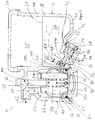
- FIG. 1 a first embodiment of an oil pan filter combination 10 of an engine oil circuit of an internal combustion engine of a motor vehicle is shown in a section.
- the oil pan-filter combination 10 comprises an oil pan 12 in which Figure 1 right, and an oil filter 14, in the Figure 1 Left.
- the oil pan 12 has an oil pan housing 16 with a peripheral wall 18 and a pan bottom 20 connected to it in one piece.
- a filter housing 22 of the oil filter 14 is integrally connected on a peripheral side to the peripheral wall 18 of the oil pan housing 16. The filter housing 22 is therefore integrated with the oil pan housing 16.
- the peripheral wall 18 On its upper edge opposite the pan bottom 20, the peripheral wall 18 has an oil pan flange 24 for attachment to an engine block (not shown) of the internal combustion engine.
- Oil is received in a pan interior 25 of the oil pan 12 and runs back into the oil pan 12 from the lubrication points and cooling points of the internal combustion engine.
- An oil sump 26 extends as far as an oil level 28.
- the pressure from the crankcase of the internal combustion engine prevails in the oil pan 12, which pressure almost corresponds to the ambient pressure in the case of an internal combustion engine that is shut down for an oil change, for example.
- the tub interior 25 can therefore be referred to as a "pressureless space".
- the operational state shown of the oil pan-filter combination 10 is closed with an oil drain screw 32.
- the oil drain opening 30 and the oil drain screw 32 are coaxial with an imaginary axis 34. They are parts of a drain device designated as a whole by 36.
- the axis 34 extends downwards at an angle to the spatial horizontal as viewed from the pan interior 25.
- the tub bottom 20 has a corresponding bulge in which the oil drain opening 30 is located.
- the oil drain screw 32 has an external thread which cooperates with a corresponding internal thread of an oil drain sealing section 40 on the side of the oil drain opening 30 as a screw connection.
- the closed state of the oil drain plug 32 shown is the oil pan closure section 38 and the oil pan sealing section 40 abut one another within the oil drain sealing area 42 and close the oil drain opening 30.
- An extension of the oil drain sealing area 42 axially to the axis 34 is provided with a reference number 44.
- oil drain screw 32 has an O-ring seal 46 in a circumferential sealing groove, which seals against a corresponding circumferential sealing surface on the side of the tub bottom 20.
- the peripheral wall 18 of the oil pan housing 16 has a housing passage 48 on its side facing the filter housing 22, which is part of the drainage device 36 and connects the tub interior 25 to a housing interior 50 of the filter housing 22.
- a sealing section 52 of the housing passage 48 on the side facing the oil drain opening 30 is coaxial with the axis 34.
- a largest diameter of the sealing section 52 is smaller than a smallest diameter of the oil drain opening 30, so that the oil drain plug 32 can be easily installed through the oil drain opening 30.
- the oil drain plug 32 has a closure section 54 which is coaxial with its longitudinal axis.
- the longitudinal axis of the oil drain screw 32 coincides with the axis 34 in the installed state and therefore has in the Figure 1 the same reference number for the sake of clarity.
- the radially outer circumferential side of the closing section 54 rests within a housing sealing area 56 on the radially inner circumferential side of the sealing section 52 and thus closes the housing passage 48.
- An axial extension of the housing sealing area 56 with respect to the axis 34 is provided with the reference numeral 58 .
- the cross section of the oil drain plug 32 tapers towards its free end.
- a circumferential sealing groove, in which an O-ring seal 60 is located, is arranged within the closure section 54.
- a sealing effect is improved, so that even if there is a pressure difference between the interior of the housing 50 and the tub interior 25, as can usually be the case when the internal combustion engine is operating, no oil can pass through the housing passage 48.
- the axial extension 58 of the housing sealing area 56 is smaller than the axial extension 44 of the oil drain sealing area 42. In this way, when the oil drain screw 32 is unscrewed, the housing passage 48 is first opened, the oil drain opening 30 remaining closed. In this way, pressure equalization can take place between the housing interior 58 and the tub interior 25. Oil can flow through the housing passage 48. Only after the oil drain screw 32 has been completely unscrewed is the oil drain opening 30 released so that the oil can flow out of the tub interior 25. In the process, any oil still contained in the housing interior 50 can flow into the tub interior 25. In this way, the housing interior 50 can also be emptied at least to the level of the housing passage 48.
- An oil inlet 62 which is connected to an oil pump, not shown, of the engine oil circuit is arranged on an upper side of the filter housing 22.
- a crude oil channel 64 leads eccentrically from the oil inlet 62 into the housing interior 50.
- a pure oil channel 68 coaxial with a filter axis 66 is connected via an oil outlet 70 to a section of the engine oil circuit which leads to the lubrication points and the cooling points.
- the filter housing 22 On its underside, the filter housing 22 has an insertion opening 72, which is coaxial with the filter axis 66, for a filter element 74.
- a circumferential wall of the filter housing 22 in the area of the introduction opening 72 has an internal thread 76 which forms a screw connection with an external thread of a cylinder section 78 of a housing cover 80.
- the housing cover 80 closes the introduction opening 72.
- a sealing groove with an O-ring seal 82 is arranged between the external thread of the cylinder section 78 and a bottom section of the housing cover 80 on the radially outer circumferential side of the cylinder section 78.
- the O-ring seal 82 interacts with a corresponding sealing surface on the radially inner circumferential side of the circumferential wall of the filter housing 22 in the region of the introduction opening 72.
- the O-ring seal 82 seals against the environment.
- the housing cover 80 can be unscrewed downwards.
- the cylinder section 78 has a plurality of circumferentially distributed passage openings 84 which extend from the radially inside to the radially outside.
- the passage openings 84 open into an annular channel 86 which runs circumferentially radially outside the cylinder section 78 in the circumferential wall of the filter housing 22.
- the annular channel 86 is connected to the housing passage 48.
- the passage openings 84 thus connect an interior space in the interior of the cylinder section 78 of the housing cover 80 via the annular channel 86 to the housing passage 48.
- the filter element 74 is located in the housing interior 50 in the interior space delimited radially on the outside by the cylinder section 78 of the housing cover 80.
- the filter element 74 is a round filter element with a zigzag folded and circumferentially closed filter medium. Overall, the filter medium has a circular cylindrical shape. The filter element 74 is arranged overall coaxially to the filter axis 66. On the front sides, the filter medium can each with one in the Figure 1 for the sake of clarity because of the end body (not shown), for example an end plate, be tightly connected.
- a support body center tube 88 is arranged in an element interior of the filter element 74.
- the support body central tube 88 has a plurality of passage openings for the oil in its peripheral wall.
- the filter element 74 is placed on a corresponding housing-side cylinder section of the filter housing 22 that is coaxial with the filter axis 66.
- the clean oil duct 68 which is open towards the element interior, runs in the cylinder section.
- a bypass valve 90 in the form of a spring-loaded bypass valve is arranged in the element interior in the region of the end face of the filter element 74 facing the housing cover 80.
- the bypass valve 90 opens a connection opening between a clean side and an unfiltered side of the filter element 74.
- the clean side of the filter element 74 is located in the element interior bounded by the filter medium; its unfiltered side is located outside the filter element 74.
- the crude oil channel 64 is also like the passage openings 84, the annular channel 86 and the housing passage 48 are connected to the raw side.
- the crude oil flows through the oil inlet 62 and the crude oil duct 64 to the housing interior 50.
- the crude oil flows from the raw side of the filter element 74 from the radial outside to the radial inside through the filter medium and is filtered there.
- the filtered pure oil passes through the pure oil duct 68 and the oil outlet 70 into the oil line of the engine oil circuit and to the lubrication points and the cooling points of the internal combustion engine.
- a pressure generated by the oil pump prevails in the filter housing 22, which pressure is greater than the pressure in the tub interior 25. Therefore, the housing interior 50 can also be referred to as a “pressure space”.
- the oil drain screw 32 is first unscrewed from the oil drain opening 30 in the opening direction.
- the housing passage 48 is first opened.
- the housing interior 50 is connected to the tub interior 25 through the passage openings 84, the annular channel 86 and the housing passage 48.
- a pressure equalization can take place between the housing interior 50 and the tub interior 25. In this case, oil can flow through the opened housing passage 48.
- the engine oil can flow out of the tub interior 25. Any oil still contained in the housing interior 50 can flow through the housing passage 48 into the tub interior 25 and also flow away.
- the housing cover 80 is then screwed downward out of the insertion opening 72 of the filter housing 22.
- the filter element 74 is pulled out of the filter housing 22 axially to the filter axis 66 downwards.
- a new filter element is installed in the opposite direction.
- the housing cover 80 is screwed into the insertion opening 72 from below.
- the oil drain screw 32 is screwed completely into the oil drain opening 30 so that it tightly closes both the oil drain opening 30 and the housing passage 48. Fresh oil can then be filled into the engine oil circuit in a manner which is not of further interest here.
- FIG 2 a second embodiment of an oil pan filter combination 10 is shown.
- the housing cover 80 additionally has a securing recess 192 on the radially outer circumferential side of its cylinder section 78.
- the fuse recess 192 is in the correct locking position of the housing cover 80, which is in the Figure 2 is shown, coaxial with the axis 34, that is, also with the sealing section 52, with the oil drain opening 30 and with the longitudinal axis of the installed oil drain screw 32.
- the oil drain plug 32 additionally has a securing section 194 which is coaxial to its longitudinal axis and, in the installed state, also to the axis 34.
- the securing section 194 protrudes into the securing recess 192 of the housing cover 80. It thus secures the housing cover 80 against undesired or unintentional unscrewing of the housing cover 80 with the oil drain screw 32 installed.
- the oil drain screw 32 can only be screwed in completely when the housing cover 80 is in its correct installation position.
- the securing recess 192 and the securing section 194 thus serve with the oil drain screw 32 as an indicator for the correct installation position of the housing cover 80.
- an oil pan 12 and a drain device 36 of an oil pan / filter combination 10 the following modifications, among others, are possible:
- the invention is not limited to oil pan filter combinations 10 of internal combustion engines of motor vehicles. Rather, it can also be used outside of automotive engineering, for example in industrial engines.
- the filter housing 22 can, instead of being arranged in one piece with the oil pan housing 16, also be arranged as a separate component on the oil pan 20.
- the filter housing 22 can preferably be attached to the oil pan 20.
- the filter housing 22 can also be integrated inside the oil pan 20, for example as a separate volume, instead of on the outside.
- the filter element 74 can also be designed as an oval round filter element with an oval cross section.
- a conical round filter element can also be provided.
- the filter medium of the filter element 74 can also be flat and closed circumferentially.
- a different type of connection preferably rotatable and / or plug-in connection, for example a bayonet-type connection, can also be provided.
- the annular channel 86 can additionally or alternatively be connected to a collecting container (not shown) into which the oil can drain out of the filter housing 22 through the housing passage 48 when the oil drain screw 32 is at least partially removed.
Landscapes
- Engineering & Computer Science (AREA)
- Mechanical Engineering (AREA)
- General Engineering & Computer Science (AREA)
- Lubrication Details And Ventilation Of Internal Combustion Engines (AREA)
Claims (7)
- Combinaison carter d'huile et filtre (10) notamment d'un système de lubrification de moteur d'un moteur à combustion interne, notamment d'un véhicule automobile, avec un carter d'huile (12), un filtre à huile (14) disposé sur ou dans le carter d'huile (12), lequel filtre à huile comprend un boîtier de filtre (22) ouvrable avec un espace intérieur du boîtier (50) dans lequel un élément filtrant (74) peut être disposé de manière à pouvoir être remplacé, l'espace intérieur du boîtier (50) du boîtier de filtre (22) étant relié au moyen d'un passage du boîtier (48), au moins au nombre d'un, à un espace intérieur du carter (25) du carter d'huile (12), lequel passage du boîtier peut être obturé par un dispositif de fermeture du passage du boîtier (32, 52, 54, 60), le carter d'huile (12) présentant un orifice de vidange d'huile (30) qui peut être obturé par un élément de fermeture (32), le passage du boîtier (48), au moins au nombre d'un, présentant une section d'étanchéité (52) sur son côté tourné vers l'orifice de vidange d'huile (30) et l'élément de fermeture (32) présentant, dans une zone tournée vers le passage du boîtier (48), une section de fermeture (54) adaptée à la section d'étanchéité (52), laquelle section de fermeture peut coopérer de manière fermante avec la section d'étanchéité (52) pour fermer le passage du boîtier (48), caractérisée en ce que la section d'étanchéité (52) et l'orifice de vidange d'huile (30) sont coaxiaux par rapport à un axe commun (34), une extension axiale (58) d'une zone d'étanchéité du boîtier (56), par rapport à l'axe commun (34), dans laquelle la section de fermeture (54), en état de fermeture de l'élément de fermeture (32), s'applique de manière étanche sur la section d'étanchéité (52) du passage du boîtier (48), étant plus petite qu'une extension axiale (44) d'une zone d'étanchéité de vidange d'huile (42) dans lequel, en état de fermeture, une section de fermeture de vidange d'huile (38) de l'élément de fermeture (32) s'applique de manière étanche sur une section d'étanchéité de vidange d'huile (40) de l'orifice de vidange d'huile (30).
- Combinaison carter d'huile et filtre selon la revendication 1, caractérisée en ce que l'axe commun (34), dans la position de montage habituelle de la combinaison carter d'huile et filtre (10), s'étend obliquement vers le bas du passage du boîtier (48) vu en direction de l'orifice de vidange d'huile (30).
- Combinaison carter d'huile et filtre selon l'une des revendications précédentes, caractérisée en ce que le boîtier de filtre (22) présente une ouverture d'insertion (72) pour l'élément filtrant (74) qui peut être obturée au moyen d'un couvercle de boîtier (80), et le couvercle de boîtier (80) présente au moins un évidement de sécurité (192), et l'élément de fermeture (32) présente une section de sécurité (194) qui, en position de montage correcte du couvercle de boîtier (80), peut venir en prise, dans l'état de fermeture de l'élément de fermeture (32), avec l'évidement de sécurité (192), au moins au nombre d'un.
- Combinaison carter d'huile et filtre selon l'une des revendications précédentes, caractérisée en ce que l'élément de fermeture (32) présente un filetage extérieur qui peut être vissé sur un filetage intérieur correspondant dans la zone de l'orifice de vidange d'huile (30).
- Combinaison carter d'huile et filtre selon l'une des revendications précédentes, caractérisée en ce qu'un joint d'étanchéité, notamment un joint torique d'étanchéité (46), est disposé entre la section de fermeture (54) de l'élément de fermeture (32) et la section d'étanchéité (52) du passage du boîtier (48).
- Combinaison carter d'huile et filtre selon l'une des revendications précédentes, caractérisée en ce qu'une section transversale de la section de fermeture (54) se rétrécit vers l'extrémité libre de l'élément de fermeture (32), notamment la section de fermeture (54) évolue de manière conique.
- Combinaison carter d'huile et filtre selon l'une des revendications précédentes caractérisée en ce que le boîtier de filtre (22) est disposé à l'extérieur du carter d'huile (12).
Applications Claiming Priority (2)
| Application Number | Priority Date | Filing Date | Title |
|---|---|---|---|
| DE102012022989 | 2012-11-26 | ||
| PCT/EP2013/053694 WO2014079591A1 (fr) | 2012-11-26 | 2013-02-25 | Combinaison de filtres de carter d'huile, carter d'huile et dispositif d'évacuation d'une combinaison de filtres de carter d'huile |
Publications (2)
| Publication Number | Publication Date |
|---|---|
| EP2923045A1 EP2923045A1 (fr) | 2015-09-30 |
| EP2923045B1 true EP2923045B1 (fr) | 2021-04-14 |
Family
ID=47757590
Family Applications (1)
| Application Number | Title | Priority Date | Filing Date |
|---|---|---|---|
| EP13706966.2A Active EP2923045B1 (fr) | 2012-11-26 | 2013-02-25 | Combinaison de filtres de carter d'huile, carter d'huile et dispositif d'évacuation d'une combinaison de filtres de carter d'huile |
Country Status (2)
| Country | Link |
|---|---|
| EP (1) | EP2923045B1 (fr) |
| WO (1) | WO2014079591A1 (fr) |
Families Citing this family (4)
| Publication number | Priority date | Publication date | Assignee | Title |
|---|---|---|---|---|
| DE102014007816B4 (de) * | 2014-06-02 | 2017-12-28 | Mann + Hummel Gmbh | Ölwannen-Filtermodul mit wenigstens einem Wannenablass und wenigstens einem Filterablass, Verschlusseinheit eines Ölwannen-Filtermoduls und Baueinheit aus einer Verschlusseinheit und einem Ölfilterelement eines Ölwannen-Filtermoduls |
| DE102014015265A1 (de) | 2014-10-16 | 2016-04-21 | Daimler Ag | Schmierölversorgungseinrichtung für eine Verbrennungskraftmaschine sowie Filtereinsatz für eine solche Schmierölversorgungseinrichtung |
| JP6661984B2 (ja) * | 2015-11-12 | 2020-03-11 | いすゞ自動車株式会社 | オイルパン装置 |
| EP4026599B1 (fr) * | 2018-01-16 | 2024-05-15 | Volvo Truck Corporation | Système d'huile moteur et couvercle |
Family Cites Families (3)
| Publication number | Priority date | Publication date | Assignee | Title |
|---|---|---|---|---|
| DE19950888A1 (de) | 1999-10-22 | 2001-04-26 | Bayerische Motoren Werke Ag | Ölfiltervorrichtung für Brennkraftmaschinen |
| DE20012736U1 (de) * | 2000-07-22 | 2000-09-21 | Filterwerk Mann + Hummel GmbH, 71638 Ludwigsburg | Baugruppe für eine Brennkraftmaschine mit einem Ölfilter |
| US8272480B2 (en) * | 2009-03-12 | 2012-09-25 | Mahle International Gmbh | Oil pan integrated with filter and other components |
-
2013
- 2013-02-25 WO PCT/EP2013/053694 patent/WO2014079591A1/fr not_active Ceased
- 2013-02-25 EP EP13706966.2A patent/EP2923045B1/fr active Active
Non-Patent Citations (1)
| Title |
|---|
| None * |
Also Published As
| Publication number | Publication date |
|---|---|
| WO2014079591A1 (fr) | 2014-05-30 |
| EP2923045A1 (fr) | 2015-09-30 |
Similar Documents
| Publication | Publication Date | Title |
|---|---|---|
| DE112013005747B4 (de) | Filter, Filterelement, Filtergehäuse und Ablassvorrichtung eines Filters | |
| EP2670503B1 (fr) | Système de filtre à huile d'un moteur à combustion interne et filtre remplaçable d'un système de filtre | |
| EP3004620B1 (fr) | Élément filtrant | |
| EP1174597B1 (fr) | Ensemble pour un moteur à combustion avec un filtre à huile | |
| DE19716085B4 (de) | Filter, insbesondere für Kraftstoffe von Verbrennungsmotoren | |
| EP1110590A2 (fr) | Filtre de liquide à dispositif de vidange de résidus liquides | |
| EP1307274A1 (fr) | Filtre a liquides | |
| DE102014010433A1 (de) | Filtrationsvorrichtung | |
| WO2013178680A1 (fr) | Système de filtre | |
| DE112014005458B4 (de) | Filterelement und Filtersystem mit Nebenstromfilterung | |
| EP2923045B1 (fr) | Combinaison de filtres de carter d'huile, carter d'huile et dispositif d'évacuation d'une combinaison de filtres de carter d'huile | |
| DE19961579A1 (de) | Flüssigkeitsfilter mit einem Kühler | |
| EP4048428B1 (fr) | Appareil de séparation pour séparer un liquide d'un gaz, en particulier de l'air, et système de séparation d'une machine | |
| EP3793707B1 (fr) | Filtre avec un boîtier et un couvercle intermédiaire | |
| DE102014007302A1 (de) | Filtervorrichtung | |
| EP3033517B1 (fr) | Filtre à liquide,notamment filtre a carburant | |
| WO2016058691A1 (fr) | Élément filtrant pour dispositif de filtration d'un moteur a combustion interne et dispositif de filtration pour moteur a combustion interne | |
| EP3352877B1 (fr) | Dispositif filtrant avec pompe | |
| WO2016008605A1 (fr) | Dispositif de filtration d'huile, couvercle de boîtier et pot de boîtier d'un dispositif de filtration d'huile | |
| DE202009001159U1 (de) | Ölabscheider | |
| DE20118683U1 (de) | Ölfilter mit Reinölrohr und drei Dichtungen | |
| DE102006005108A1 (de) | Zylindrische Filtereinrichtung | |
| DE3613093C2 (fr) | ||
| DE112008003133B4 (de) | Ölfiltersystem eines Verbrennungsmotors | |
| DE19707600A1 (de) | Deckel für ein Filtergehäuse |
Legal Events
| Date | Code | Title | Description |
|---|---|---|---|
| PUAI | Public reference made under article 153(3) epc to a published international application that has entered the european phase |
Free format text: ORIGINAL CODE: 0009012 |
|
| 17P | Request for examination filed |
Effective date: 20150414 |
|
| AK | Designated contracting states |
Kind code of ref document: A1 Designated state(s): AL AT BE BG CH CY CZ DE DK EE ES FI FR GB GR HR HU IE IS IT LI LT LU LV MC MK MT NL NO PL PT RO RS SE SI SK SM TR |
|
| AX | Request for extension of the european patent |
Extension state: BA ME |
|
| DAX | Request for extension of the european patent (deleted) | ||
| STAA | Information on the status of an ep patent application or granted ep patent |
Free format text: STATUS: EXAMINATION IS IN PROGRESS |
|
| 17Q | First examination report despatched |
Effective date: 20180718 |
|
| RAP1 | Party data changed (applicant data changed or rights of an application transferred) |
Owner name: MANN + HUMMEL GMBH |
|
| GRAP | Despatch of communication of intention to grant a patent |
Free format text: ORIGINAL CODE: EPIDOSNIGR1 |
|
| STAA | Information on the status of an ep patent application or granted ep patent |
Free format text: STATUS: GRANT OF PATENT IS INTENDED |
|
| INTG | Intention to grant announced |
Effective date: 20201120 |
|
| GRAS | Grant fee paid |
Free format text: ORIGINAL CODE: EPIDOSNIGR3 |
|
| GRAA | (expected) grant |
Free format text: ORIGINAL CODE: 0009210 |
|
| STAA | Information on the status of an ep patent application or granted ep patent |
Free format text: STATUS: THE PATENT HAS BEEN GRANTED |
|
| AK | Designated contracting states |
Kind code of ref document: B1 Designated state(s): AL AT BE BG CH CY CZ DE DK EE ES FI FR GB GR HR HU IE IS IT LI LT LU LV MC MK MT NL NO PL PT RO RS SE SI SK SM TR |
|
| REG | Reference to a national code |
Ref country code: GB Ref legal event code: FG4D Free format text: NOT ENGLISH |
|
| REG | Reference to a national code |
Ref country code: CH Ref legal event code: EP |
|
| REG | Reference to a national code |
Ref country code: DE Ref legal event code: R096 Ref document number: 502013015650 Country of ref document: DE |
|
| REG | Reference to a national code |
Ref country code: IE Ref legal event code: FG4D Free format text: LANGUAGE OF EP DOCUMENT: GERMAN |
|
| REG | Reference to a national code |
Ref country code: AT Ref legal event code: REF Ref document number: 1382561 Country of ref document: AT Kind code of ref document: T Effective date: 20210515 |
|
| RAP4 | Party data changed (patent owner data changed or rights of a patent transferred) |
Owner name: MANN+HUMMEL GMBH |
|
| REG | Reference to a national code |
Ref country code: LT Ref legal event code: MG9D |
|
| REG | Reference to a national code |
Ref country code: NL Ref legal event code: MP Effective date: 20210414 |
|
| PG25 | Lapsed in a contracting state [announced via postgrant information from national office to epo] |
Ref country code: FI Free format text: LAPSE BECAUSE OF FAILURE TO SUBMIT A TRANSLATION OF THE DESCRIPTION OR TO PAY THE FEE WITHIN THE PRESCRIBED TIME-LIMIT Effective date: 20210414 Ref country code: NL Free format text: LAPSE BECAUSE OF FAILURE TO SUBMIT A TRANSLATION OF THE DESCRIPTION OR TO PAY THE FEE WITHIN THE PRESCRIBED TIME-LIMIT Effective date: 20210414 Ref country code: LT Free format text: LAPSE BECAUSE OF FAILURE TO SUBMIT A TRANSLATION OF THE DESCRIPTION OR TO PAY THE FEE WITHIN THE PRESCRIBED TIME-LIMIT Effective date: 20210414 Ref country code: BG Free format text: LAPSE BECAUSE OF FAILURE TO SUBMIT A TRANSLATION OF THE DESCRIPTION OR TO PAY THE FEE WITHIN THE PRESCRIBED TIME-LIMIT Effective date: 20210714 Ref country code: HR Free format text: LAPSE BECAUSE OF FAILURE TO SUBMIT A TRANSLATION OF THE DESCRIPTION OR TO PAY THE FEE WITHIN THE PRESCRIBED TIME-LIMIT Effective date: 20210414 |
|
| PG25 | Lapsed in a contracting state [announced via postgrant information from national office to epo] |
Ref country code: ES Free format text: LAPSE BECAUSE OF FAILURE TO SUBMIT A TRANSLATION OF THE DESCRIPTION OR TO PAY THE FEE WITHIN THE PRESCRIBED TIME-LIMIT Effective date: 20210414 Ref country code: PL Free format text: LAPSE BECAUSE OF FAILURE TO SUBMIT A TRANSLATION OF THE DESCRIPTION OR TO PAY THE FEE WITHIN THE PRESCRIBED TIME-LIMIT Effective date: 20210414 Ref country code: NO Free format text: LAPSE BECAUSE OF FAILURE TO SUBMIT A TRANSLATION OF THE DESCRIPTION OR TO PAY THE FEE WITHIN THE PRESCRIBED TIME-LIMIT Effective date: 20210714 Ref country code: PT Free format text: LAPSE BECAUSE OF FAILURE TO SUBMIT A TRANSLATION OF THE DESCRIPTION OR TO PAY THE FEE WITHIN THE PRESCRIBED TIME-LIMIT Effective date: 20210816 Ref country code: LV Free format text: LAPSE BECAUSE OF FAILURE TO SUBMIT A TRANSLATION OF THE DESCRIPTION OR TO PAY THE FEE WITHIN THE PRESCRIBED TIME-LIMIT Effective date: 20210414 Ref country code: GR Free format text: LAPSE BECAUSE OF FAILURE TO SUBMIT A TRANSLATION OF THE DESCRIPTION OR TO PAY THE FEE WITHIN THE PRESCRIBED TIME-LIMIT Effective date: 20210715 Ref country code: IS Free format text: LAPSE BECAUSE OF FAILURE TO SUBMIT A TRANSLATION OF THE DESCRIPTION OR TO PAY THE FEE WITHIN THE PRESCRIBED TIME-LIMIT Effective date: 20210814 Ref country code: SE Free format text: LAPSE BECAUSE OF FAILURE TO SUBMIT A TRANSLATION OF THE DESCRIPTION OR TO PAY THE FEE WITHIN THE PRESCRIBED TIME-LIMIT Effective date: 20210414 Ref country code: RS Free format text: LAPSE BECAUSE OF FAILURE TO SUBMIT A TRANSLATION OF THE DESCRIPTION OR TO PAY THE FEE WITHIN THE PRESCRIBED TIME-LIMIT Effective date: 20210414 |
|
| REG | Reference to a national code |
Ref country code: DE Ref legal event code: R097 Ref document number: 502013015650 Country of ref document: DE |
|
| PG25 | Lapsed in a contracting state [announced via postgrant information from national office to epo] |
Ref country code: RO Free format text: LAPSE BECAUSE OF FAILURE TO SUBMIT A TRANSLATION OF THE DESCRIPTION OR TO PAY THE FEE WITHIN THE PRESCRIBED TIME-LIMIT Effective date: 20210414 Ref country code: EE Free format text: LAPSE BECAUSE OF FAILURE TO SUBMIT A TRANSLATION OF THE DESCRIPTION OR TO PAY THE FEE WITHIN THE PRESCRIBED TIME-LIMIT Effective date: 20210414 Ref country code: DK Free format text: LAPSE BECAUSE OF FAILURE TO SUBMIT A TRANSLATION OF THE DESCRIPTION OR TO PAY THE FEE WITHIN THE PRESCRIBED TIME-LIMIT Effective date: 20210414 Ref country code: CZ Free format text: LAPSE BECAUSE OF FAILURE TO SUBMIT A TRANSLATION OF THE DESCRIPTION OR TO PAY THE FEE WITHIN THE PRESCRIBED TIME-LIMIT Effective date: 20210414 Ref country code: SK Free format text: LAPSE BECAUSE OF FAILURE TO SUBMIT A TRANSLATION OF THE DESCRIPTION OR TO PAY THE FEE WITHIN THE PRESCRIBED TIME-LIMIT Effective date: 20210414 Ref country code: SM Free format text: LAPSE BECAUSE OF FAILURE TO SUBMIT A TRANSLATION OF THE DESCRIPTION OR TO PAY THE FEE WITHIN THE PRESCRIBED TIME-LIMIT Effective date: 20210414 |
|
| PLBE | No opposition filed within time limit |
Free format text: ORIGINAL CODE: 0009261 |
|
| STAA | Information on the status of an ep patent application or granted ep patent |
Free format text: STATUS: NO OPPOSITION FILED WITHIN TIME LIMIT |
|
| 26N | No opposition filed |
Effective date: 20220117 |
|
| PG25 | Lapsed in a contracting state [announced via postgrant information from national office to epo] |
Ref country code: IS Free format text: LAPSE BECAUSE OF FAILURE TO SUBMIT A TRANSLATION OF THE DESCRIPTION OR TO PAY THE FEE WITHIN THE PRESCRIBED TIME-LIMIT Effective date: 20210814 Ref country code: AL Free format text: LAPSE BECAUSE OF FAILURE TO SUBMIT A TRANSLATION OF THE DESCRIPTION OR TO PAY THE FEE WITHIN THE PRESCRIBED TIME-LIMIT Effective date: 20210414 |
|
| PG25 | Lapsed in a contracting state [announced via postgrant information from national office to epo] |
Ref country code: IT Free format text: LAPSE BECAUSE OF FAILURE TO SUBMIT A TRANSLATION OF THE DESCRIPTION OR TO PAY THE FEE WITHIN THE PRESCRIBED TIME-LIMIT Effective date: 20210414 |
|
| PG25 | Lapsed in a contracting state [announced via postgrant information from national office to epo] |
Ref country code: MC Free format text: LAPSE BECAUSE OF FAILURE TO SUBMIT A TRANSLATION OF THE DESCRIPTION OR TO PAY THE FEE WITHIN THE PRESCRIBED TIME-LIMIT Effective date: 20210414 |
|
| REG | Reference to a national code |
Ref country code: CH Ref legal event code: PL |
|
| REG | Reference to a national code |
Ref country code: BE Ref legal event code: MM Effective date: 20220228 |
|
| GBPC | Gb: european patent ceased through non-payment of renewal fee |
Effective date: 20220225 |
|
| PG25 | Lapsed in a contracting state [announced via postgrant information from national office to epo] |
Ref country code: LU Free format text: LAPSE BECAUSE OF NON-PAYMENT OF DUE FEES Effective date: 20220225 |
|
| PG25 | Lapsed in a contracting state [announced via postgrant information from national office to epo] |
Ref country code: FR Free format text: LAPSE BECAUSE OF NON-PAYMENT OF DUE FEES Effective date: 20220228 |
|
| PG25 | Lapsed in a contracting state [announced via postgrant information from national office to epo] |
Ref country code: LI Free format text: LAPSE BECAUSE OF NON-PAYMENT OF DUE FEES Effective date: 20220228 Ref country code: IE Free format text: LAPSE BECAUSE OF NON-PAYMENT OF DUE FEES Effective date: 20220225 Ref country code: GB Free format text: LAPSE BECAUSE OF NON-PAYMENT OF DUE FEES Effective date: 20220225 Ref country code: CH Free format text: LAPSE BECAUSE OF NON-PAYMENT OF DUE FEES Effective date: 20220228 |
|
| PG25 | Lapsed in a contracting state [announced via postgrant information from national office to epo] |
Ref country code: BE Free format text: LAPSE BECAUSE OF NON-PAYMENT OF DUE FEES Effective date: 20220228 |
|
| REG | Reference to a national code |
Ref country code: AT Ref legal event code: MM01 Ref document number: 1382561 Country of ref document: AT Kind code of ref document: T Effective date: 20220225 |
|
| PG25 | Lapsed in a contracting state [announced via postgrant information from national office to epo] |
Ref country code: AT Free format text: LAPSE BECAUSE OF NON-PAYMENT OF DUE FEES Effective date: 20220225 |
|
| PG25 | Lapsed in a contracting state [announced via postgrant information from national office to epo] |
Ref country code: HU Free format text: LAPSE BECAUSE OF FAILURE TO SUBMIT A TRANSLATION OF THE DESCRIPTION OR TO PAY THE FEE WITHIN THE PRESCRIBED TIME-LIMIT; INVALID AB INITIO Effective date: 20130225 |
|
| PG25 | Lapsed in a contracting state [announced via postgrant information from national office to epo] |
Ref country code: MK Free format text: LAPSE BECAUSE OF FAILURE TO SUBMIT A TRANSLATION OF THE DESCRIPTION OR TO PAY THE FEE WITHIN THE PRESCRIBED TIME-LIMIT Effective date: 20210414 Ref country code: CY Free format text: LAPSE BECAUSE OF FAILURE TO SUBMIT A TRANSLATION OF THE DESCRIPTION OR TO PAY THE FEE WITHIN THE PRESCRIBED TIME-LIMIT Effective date: 20210414 |
|
| PGFP | Annual fee paid to national office [announced via postgrant information from national office to epo] |
Ref country code: DE Payment date: 20240219 Year of fee payment: 12 |
|
| PG25 | Lapsed in a contracting state [announced via postgrant information from national office to epo] |
Ref country code: TR Free format text: LAPSE BECAUSE OF FAILURE TO SUBMIT A TRANSLATION OF THE DESCRIPTION OR TO PAY THE FEE WITHIN THE PRESCRIBED TIME-LIMIT Effective date: 20210414 |
|
| PG25 | Lapsed in a contracting state [announced via postgrant information from national office to epo] |
Ref country code: MT Free format text: LAPSE BECAUSE OF FAILURE TO SUBMIT A TRANSLATION OF THE DESCRIPTION OR TO PAY THE FEE WITHIN THE PRESCRIBED TIME-LIMIT Effective date: 20210414 |
|
| REG | Reference to a national code |
Ref country code: DE Ref legal event code: R119 Ref document number: 502013015650 Country of ref document: DE |
|
| PG25 | Lapsed in a contracting state [announced via postgrant information from national office to epo] |
Ref country code: DE Free format text: LAPSE BECAUSE OF NON-PAYMENT OF DUE FEES Effective date: 20250902 |