EP2923123B1 - Dispositif d'administration de médicament avec microclapet anti-retour - Google Patents
Dispositif d'administration de médicament avec microclapet anti-retour Download PDFInfo
- Publication number
- EP2923123B1 EP2923123B1 EP13799401.8A EP13799401A EP2923123B1 EP 2923123 B1 EP2923123 B1 EP 2923123B1 EP 13799401 A EP13799401 A EP 13799401A EP 2923123 B1 EP2923123 B1 EP 2923123B1
- Authority
- EP
- European Patent Office
- Prior art keywords
- membrane
- valve
- valve seat
- micro
- delivery device
- Prior art date
- Legal status (The legal status is an assumption and is not a legal conclusion. Google has not performed a legal analysis and makes no representation as to the accuracy of the status listed.)
- Active
Links
Images


Classifications
-
- F—MECHANICAL ENGINEERING; LIGHTING; HEATING; WEAPONS; BLASTING
- F16—ENGINEERING ELEMENTS AND UNITS; GENERAL MEASURES FOR PRODUCING AND MAINTAINING EFFECTIVE FUNCTIONING OF MACHINES OR INSTALLATIONS; THERMAL INSULATION IN GENERAL
- F16K—VALVES; TAPS; COCKS; ACTUATING-FLOATS; DEVICES FOR VENTING OR AERATING
- F16K99/00—Subject matter not provided for in other groups of this subclass
- F16K99/0001—Microvalves
- F16K99/0003—Constructional types of microvalves; Details of the cutting-off member
- F16K99/0015—Diaphragm or membrane valves
-
- F—MECHANICAL ENGINEERING; LIGHTING; HEATING; WEAPONS; BLASTING
- F16—ENGINEERING ELEMENTS AND UNITS; GENERAL MEASURES FOR PRODUCING AND MAINTAINING EFFECTIVE FUNCTIONING OF MACHINES OR INSTALLATIONS; THERMAL INSULATION IN GENERAL
- F16K—VALVES; TAPS; COCKS; ACTUATING-FLOATS; DEVICES FOR VENTING OR AERATING
- F16K15/00—Check valves
- F16K15/14—Check valves with flexible valve members
- F16K15/144—Check valves with flexible valve members the closure elements being fixed along all or a part of their periphery
-
- F—MECHANICAL ENGINEERING; LIGHTING; HEATING; WEAPONS; BLASTING
- F16—ENGINEERING ELEMENTS AND UNITS; GENERAL MEASURES FOR PRODUCING AND MAINTAINING EFFECTIVE FUNCTIONING OF MACHINES OR INSTALLATIONS; THERMAL INSULATION IN GENERAL
- F16K—VALVES; TAPS; COCKS; ACTUATING-FLOATS; DEVICES FOR VENTING OR AERATING
- F16K99/00—Subject matter not provided for in other groups of this subclass
- F16K99/0001—Microvalves
- F16K99/0034—Operating means specially adapted for microvalves
- F16K99/0055—Operating means specially adapted for microvalves actuated by fluids
- F16K99/0057—Operating means specially adapted for microvalves actuated by fluids the fluid being the circulating fluid itself, e.g. check valves
-
- F—MECHANICAL ENGINEERING; LIGHTING; HEATING; WEAPONS; BLASTING
- F16—ENGINEERING ELEMENTS AND UNITS; GENERAL MEASURES FOR PRODUCING AND MAINTAINING EFFECTIVE FUNCTIONING OF MACHINES OR INSTALLATIONS; THERMAL INSULATION IN GENERAL
- F16K—VALVES; TAPS; COCKS; ACTUATING-FLOATS; DEVICES FOR VENTING OR AERATING
- F16K15/00—Check valves
- F16K15/14—Check valves with flexible valve members
Definitions
- micro-pumps for the delivery of pharmaco active agents demands high levels of performance. Insulin pumps are required to deliver medication at dose rate increments of between 0.25 and 0.5 Units of insulin per hour. When used to deliver standard U100 insulin this translates to fluid flow rate increments of 25 and 50 ⁇ l of medication per hour.
- the current standard for flow delivery defines a flow rate accuracy of better than +/- 5% of the flow rate the pump is programmed to deliver. This translates to a flow rate accuracy of +/-0.75 and 2.50 ⁇ l of medication per hour. Micro-pumps designed for these purposes therefore need to avoid design features that can generate medication delivery errors of this magnitude.
- Micro pumps have been proposed for delivering medication particularly in applications where the dosing accuracy is very high and there is a requirement for portability of the medication system. While a number of micro pump designs have been described, pulsatile micro pumps have found applications in medication delivery.
- Passive, normally closed one way membrane micro valve designs are commonly employed in micro pump design because they present a number of advantages.
- the construction of these micro valves typically comprises a membrane that serves to separate the fluid at the inlet to the pumping chamber from that present in the pumping chamber in the case of the inlet micro valve, or serves to separate the fluid present in the pumping chamber from that at the outlet of the pumping chamber in the case of the micro valve on the outlet.
- This membrane seals across a conduit that carries fluid across the micro valve structure. In normally closed micro valves, this membrane seals across the conduit and prevents the flow of fluid across the valve.
- the valve membrane seals onto a valve seat structure incorporated into the conduit and designed to accommodate at least part of the membrane and create a good fluidic seal.
- micro pumps that contribute to inaccurate fluid delivery are known.
- the pumping chamber is designed in such a way that the pumping piston displaces all the volume enclosed by the pumping chamber. This also includes any volume of liquid connecting the pumping chamber to the outlet of the micro valve and the volume of fluid connecting the pumping chamber to the outlet micro valve.
- a micro-pump designed for insulin delivery and which meets the current performance standard it is not desirable that when the piston enters the pumping chamber the displacement of liquid varies by more than +/- 2.5 ⁇ l.
- the pumping chamber volume fills completely with liquid and is devoid of air bubbles.
- the design of the pumping chamber therefore has to avoid features that could either trap air during initial filing of the pump with liquid or retains air bubbles if they accidentally enter the pumping chamber via the inlet. Air in the pumping chamber has the effect of reducing the volume of liquid displaced during the stroke volume. In the case of a micro-pump designed for insulin delivery and which meets the current performance standard, it is not desirable that the displacement of liquid when the piston enters the pumping chamber does not vary by more than +/- 2.5 ⁇ l.
- the design of the micro valves at both the inlet and outlet of the pumping chamber integrates with the design of the pumping chamber, and that the resulting design avoids significant volumes that will not by expelled during the dispense stroke of the pump, and also avoids features that may encourage the retention of air bubbles within the pumping chamber volume.
- the efficient delivery of the stroke volume can also be reduced if the pumping chamber is not completely contained within a rigid structure.
- the presence of the valve membrane in both the inlet and outlet valves could result in at least part of the pumping chamber being flexible, absorbing some of the displaced volume created by the pumping piston and reducing the volume of fluid displaced. It is therefore important to ensure that while the valve membrane can flex to release the seal on the valve seat and allow liquid flow, it cannot flex at any other part of the valve.
- it is not desirable that the displacement of liquid when the piston enters the pumping chamber does not vary by more than +/- 2.5 ⁇ l. In relation to the design of micro valves, this requires that the micro valve volume that is connected to the pumping chamber does not expand by more than 2. or contract by more than 2.5 ⁇ l.
- micro valve on the inlet of a micro pump is required to allow flow of liquid as soon as the pressure at the micro valve inlet increases above the pressure at the outlet side of the inlet vale, and that this flow of liquid is unrestricted. This ensures that when the piston retracts from the pumping chamber, liquid enters the chamber from the inlet micro valve more efficiently, and the design of the micro pump can avoid having to employ methods and devices that increase the effective pressure of any reservoir providing liquid to the micro pump. Also it ensures that the pump can cycle quickly between fill strokes, when the piston retracts from the pumping chamber, and dispense strokes, when the piston enters the pumping chamber.
- the micro valve on the inlet to the micro pump is required to allow flow at a pressure difference of less than 1 Atm. It is also required to allow at least 33 ⁇ l/sec flow rate if the micro pump is to support the medication dispense rates that are typical of insulin delivery therapies using U100 insulin.
- micro valve on the outlet of the micro pump prevents flow from the inlet to the outlet of the micro valve except when the pumping piston enters the pumping membrane during the dispense stroke, and so prevents leakage of fluid through the pump when the pump is at rest.
- a micro pump delivering insulin at normal atmospheric conditions would require an outlet valve capable of preventing liquid flow upto a pressure difference across the valve membrane of 2 atms. If the reservoir supplying the insulin is pressurised to aid filling of the pumping chamber, the valve on the outlet of the pump may need to prevent flow at higher pressures.
- medication delivery products that can be manufactured at low cost and in large numbers. These medication delivery systems are not intended to be used continuously but to be replaced on a periodic basis, and once the delivery system has operated for the intended duration.
- Medication delivery products designed for the delivery of insulin may require that a single device may be used for upto a period of three days before the components in contact with the insulin are discarded and replaced with new ones. This requires that the product can be manufactured and assembled using methods and processes that are cost effective.
- the device has to be manufactured from materials approved for use with the medication and can be sterilised prior to use using cost effective sterilisation processes. It is also required that the manufacturing and assembly processes produce devices that have equivalent performance characteristics. The combination of these requirements places imposes significant restrictions on the design of medication delivery devices.
- a micro pump designed for use with certain medications may be required to operate efficiently even when particulate material is present in the medium.
- the insulin protein in commonly used diabetes medications is known to aggregate to form particles and fibres. These particles or fibres can be large enough to become trapped in certain features of a medication delivery system. Examples of these features are liquid sealing areas such as those found in membrane valves. This can cause the sealing of the valve to become less efficient and affect the performance of the medication delivery system.
- micro-valves have been described that could be used as part of the design for a micro pump. They include both passive and active devices. Passive micro valves are generally preferred over active valves due to their simple construction and design. Passive micro-valves are predominantly designed to provide fluid flow selectively in one direction, requiring a build-up of pressure by the fluid on one side of the valve, and in the direction the micro-valve is designed to allow flow.
- the valve allows flow of the fluid in the intended direction of flow, while preventing the flow of fluid in the reverse direction.
- sealing between the parts incorporated into the design to prevent reverse flow of fluid is of primary importance.
- these parts are required to break the seal formed between them to allow fluid to flow in the intended direction. In some cases, it is desirable if the breaking of this seal only occurs above a certain build up of fluid pressure in the direction of intended flow.
- elastomeric materials in the construction of fluid controlling valves has been known for some time. Specifically, the use of elastomeric materials in the construction of micro-valves has also been described. The use of elastomeric materials for these purposes provides an advantage since they can continue to provide the effective sealing for which they are responsible even in the presence of particles in the liquid.
- valves where the valve membrane seals onto a valve seat that is essentially planar to the valve membrane and essentially parallel to that membrane.
- These designs have been embodied as essentially planar membranes sealing onto planar valve seats, essentially planar membranes sealing onto a raised valve seat and a further modification of this embodiment to include raise ridges on the valve seat to enhance the sealing between the membrane and the valve seat.
- the valve seat is reduced to form only a raised annular ring onto which the membrane seals.
- valves have been described where the membrane is further modified to include raised annular ridges that enhance the sealing of the membrane onto the valve seat.
- US3827456A describes a valve design that incorporates many of the features described above.
- US3827456A describes a valve where the elastomeric valve membrane has a central hole at the centre of a annular raised bead that seats on top of an annular valve seat so that it seals on the surface at the top of the valve seat.
- the elastomeric membrane is stretched over the seat to provide an efficient sealing force.
- the inlets to the vale are arranged circumferentially around the annular valve seat.
- the valve membrane also has a thickening of the external annular portion to facilitate its positioning into the valve structure.
- Valve designs are further characterised by having one of at least two embodiments.
- the first incorporates a valve membrane that is held in close proximity to the valve seat and relies on at least some influence from the fluid in the valve to affect its sealing onto the valve seat. These valves seal only when the pressure difference between one side to the sealing membrane and the other is high enough and in the correct direction to seal the membrane against the valve seat.
- the second incorporates a valve membrane that is held against the valve seat either by the tension in the valve membrane or by a structure used to force the membrane against the valve seat.
- An example of the first is a membrane stretched over a pillar shaped valve seat.
- An embodiment of the latter is a membrane held in place by a spring, acting on the membrane to force it against the valve seat.
- US4493339A describes a valve having a valve membrane with a raised annular section that when seated onto a flat valve seat creates the sealing force for the valve.
- the valve membrane also has a thickened outer annular segment that is used to locate the membrane into the valve construction and help retain the valve under correct tension against the valve seat.
- a cross sectional view of the valve membrane shows that the raised annular section that forms the seal for the valve is lower than the edge of the thickened outer annular segment.
- US 3176712A describes a valve incorporating a valve membrane stretched over a semispherical valve seat.
- the valve seat is located over a base pate perforated to allow fluid to past through it. Fluid can then leak past the seal between the valve seat and the valve membrane if there is sufficient pressure to do so.
- the membrane has a centrally located hole that is normally blocked by the semi spherical valve seat, but through which fluid flows when the seal is broken.
- valve membranes that are structured to provide the membrane with regions of different structural strength, and to allow the valve to operate.
- US4143853A describes a valve based on a valve membrane that has a slit cut into the central portion such that the slit opens to allow flow but seals when flow is reversed through the valve.
- the valve membrane has a thickening around the central flexible portion to provide the membrane with a ring of structural material that assists in keeping the membrane in tension and the slit in a normally closed position.
- US4770740A describes a micro valve and a method for manufacturing it that comprises a flexible nickel valve membrane that has an inner portion that seals against the valve seat and creates the sealing for the valve.
- the valve membrane is fabricated from a single sheet of nickel that is structured to provide the flexible valve sealing portion and a rigid frame that retains this flexible portion in position and under tension. The two are connected by a series of supporting arms.
- Valve designs that incorporate a flexible membrane forcibly held against a valve seat are preferred in the design of micro pumps where very low displacement volumes are common. They are also preferred for other very low flow rate applications. These valve designs have the greatest potential to prevent reverse flow of liquid even at very low back pressures.
- the micro-valve design creates a structure where only a very small section of the device is important to the sealing performance of the micro-valve. Moving the sealing surface away from the inlet hole creates new opportunities for micro-valve designs.
- Micro-valve designs such as described in GB2443260B require that the pillar that comprises the valve seat is large enough to allow a through hole to be formed in the centre of the pillar to provide the inlet to the micro-valve.
- Current fabrication technologies restrict the minimum radius that can be achieved for this through hole, and also restrict the wall thickness between the hole and the outer diameter of the pillar. Furthermore, the total cross-section area of the inlet hole available for fluid flow is restricted by these limitations.
- CA1301244C describes a valve device that also seals at a junction between the sealing membrane and the surface of the valve seat.
- CA1301244C describes the use of a conical valve seat as a further improvement to the device.
- CA1301244C describes a relatively large valve that cannot be readily replicated using micro fabrication techniques and for the construction of a micro-valve.
- the limitations described in relation to GB2443260B apply to this design. Specifically, the location of the inlet for the valve at the centre of the valve seat and the limitations imposed by fabrication techniques relative to this featu re.
- the hole in the micro valve membrane preferably provides the fluidic conduit from the inlet side of the micro valve to the outlet side of the micro valve.
- the valve seat preferably protrudes sufficiently through the hole and the hole is sufficiently small so that the micro valve seat seals onto the edge of the hole in the micro valve membrane.
- the sealing may be between the surface of the micro-valve seat and the surface of the membrane contacting the peripheral face of the valve seat. The sealing is preferably sufficient to prevent flow of fluid from the outlet side of the micro valve to the inlet side of the micro valve, but when the pressure difference between the inlet side of the micro valve and the outlet side of the micro valve is sufficiently positive, the membrane is deflected away from the micro valve seat and fluid is allowed to flow between the valve seat and the hole in the membrane.
- the conical shape of the micro valve seat allows the micro valve seat to seal effectively onto the edge of the membrane.
- the conical shape of the micro valve seat also allows the seat to be located into the hole in the flexible membrane. This aids alignment between the hole in the membrane and the valve seat.
- the conical valve seat may be located into the hole in the membrane, and then pushed further through the hole thereby stretching the diameter of the hole. This serves to improve the sealing of the flexible micro valve membrane onto the valve seat.
- the angle of the conical surface relative to the micro valve membrane, and the amount by which the valve seat penetrates through the hole in the membrane can be adjusted to either increase or decrease the level of fluidic sealing produced at the interface between the surface of the conical valve seat and the outer periphery of the hole in the valve membrane.
- the level of fluidic sealing can also be adjusted by adjusting the geometrical dimensions of the hole in the membrane relative to the geometrical dimensions of the valve seat, in particular the diameter of the valve seat in the region where it contacts the hole in the membrane, once the valve seat is fully located into the hole in the membrane.
- the micro pump may comprise at least three parts.
- a first body portion comprising the micro valve seat, a second body portion structured to align with the first body portion and the micro valve membrane held between the first and second body portions, and that aligns with the first and second body portions.
- the first body portion may have a fluidic inlet that is in fluidic contact with the hole in the micro valve membrane when the valve is open.
- the second body portion may have a fluidic outlet that is fluidic connection with the hole in the membrane.
- the second body portion may have a chamber formed to allow the membrane to move when the micro valve opens, and which is located over the valve seat on the first body portion.
- the three parts can be held together by adhesive bonding, with the use of a clamp, held together in a housing, joined by thermal bonding or by any other method that will be apparent to one practiced in the art.
- the three parts can be aligned either by the use of alignment posts or by aligning the peripheral edge of the parts.
- the surface of the valve membrane contacting the surface of the first body portion incorporating the micro valve seat may be mechanically supported by the surface of the first body portion to prevent the membrane from flexing when the pressure on the outlet side of the micro valve increases, relative to the pressure at the inlet side of the membrane.
- the fluid inlet of the first body portion may be spatially separated from the valve seat structure.
- the fluidic inlet to the valve can be provided by fluidic conduits through the first body.
- the cross section dimension of the opening of these conduits can be reduced to reduce or avoid sections of the membrane that are not supported by the first body part.
- the fluidic conduits comprising the inlet can also be located in areas of the first body part that do not contribute to the mechanical support offered by the first body part to the membrane.
- the flow rate can be maximised through the micro valve by incorporating a number of conduits that collectively form the inlet.
- the fluidic inlet can be a conduit that is formed between the surface of the first body portion and the membrane.
- the fluidic conduit can be designed to maximise flow rate while retaining the mechanical support provided by the first body part to the membrane.
- the diameter of the hole in the membrane can be adapted to offer the best flow rate characteristics for the micro valve while still provide efficient sealing when the pressure at the outlet of the micro valve exceeds the pressure at the inlet.
- One advantage of embodiments of this invention is that flow rate through the micro valve can be optimised without increasing the opportunity for the membrane to flex when the pressure at the outlet to the micro valve increases relative to the pressure at the inlet.
- Another advantage of embodiments of this invention is that the first body portion offers structural support to the flexible membrane and therefore minimises the flexing of the membrane when the pressure at the outlet of the micro valve is greater than the pressure at the inlet. This allows the micro valve to be used in micro pump designs that require rigid boundaries within the region of the pumping chamber.
- Another advantage of embodiments of this invention is the simple construction of the micro valve.
- Another advantage of embodiments of this invention is that the design can be adapted to create micro valves with different performance characteristics. This includes valves that all seal efficiently when the pressure at the outlet exceeds the pressure at the inlet, but that vary with regard to the excess pressure required at the inlet relative to the outlet to deflect the membrane from the valve seat and allow fluid flow.
- micro valve is simple and avoids fabrication processes that would otherwise make the manufacture of this micro valve difficult or expensive when produced in large numbers and for low cost applications.
- the features critical to the efficient functioning of the micro valve can be fabricated using industry standard processes for the fabrication of low cost parts in high volumes.
- the sealing surface of the cone shaped micro valve seat is the sloping surface of the valve seat. This feature can be defined with accuracy and repeatability when employing industry standard injection moulding techniques.
- the membrane is a flexible member which applies a force on the valve seat when the surface of the valve seat seals onto the inner periphery of the hole in the membrane.
- the one way valve comprises an inlet side and an outlet side and the membrane is configured to deflect from the surface of the valve seat at a specific pressure difference between the inlet side and the outlet side.
- the membrane is selectively supported around an outer peripheral portion of the membrane such that deflection is restricted to an inner portion of the membrane.
- the hole in the membrane is formed in the inner portion of the membrane.
- the one way valve further comprises a first body portion that includes the valve seat.
- the one way valve further comprises a mechanical stop to restrict the deflection of the membrane towards the valve seat and the first body portion.
- the mechanical stop restricts deflection of the membrane towards the valve seat and the first body portion when the surface of the valve seat seals onto the inner periphery of the hole in the membrane.
- the mechanical stop forms part of the valve seat.
- the mechanical stop forms part of the first body portion.
- the first body portion has a fluid conduit formed to provide an inlet of the one way valve.
- an aperture is formed at a base of the valve seat, which aperture forms part of the fluid path across the membrane.
- multiple apertures are formed at a base of the valve seat, which apertures form part of the fluid path across the membrane.
- the fluid conduit is formed as an aperture on the outer peripheral portion of the membrane.
- the at least one aperture is formed as part of the mechanical stop.
- the one way valve further comprises a second body portion on an opposite side of the membrane to the first body portion.
- the second body portion comprises a fluid conduit formed there through defining an outlet of the one way valve.
- a cavity is defined by a recess in the second body portion into which the membrane moves when the valve opens.
- the cavity creates a fluid path from the hole in the membrane to the outlet of the valve.
- the membrane is of a material selected from a group of materials including: rubber, silicone, and an elastomer.
- Fig. 1 Shows a drawing of a cross section of the micro valve described in the present invention.
- the one way micro valve 100 comprises bottom housing 7 (also referred to as first body portion), and a top housing 6 (also referred to as second body portion), and a membrane 2 held between them.
- the parts can be held together using one or more of a number of methods, including adhesive bonding, thermal bonding, or by the use of external mechanical fixations or clamps. Those practiced in the art will appreciate the variety of methods available for this purpose.
- the bottom housing comprises a conical shaped valve seat 1.
- the conical shaped valve seat 1 has a surface 60.
- channels 4 also referred to as apertures
- the channels 4 are located at the inlet side of the micro valve 100.
- the membrane 2 is formed from elastomeric material.
- a hole 3 is formed in the membrane 2.
- the hole 3 comprises an inner periphery 61.
- the valve seat 1, is located in the hole 3 and protrudes through the hole 3 such that the membrane 2 is deflected by the valve seat 1, and valve seat 1 forms a seal on the hole 3 of the membrane.
- the surface 60 of the valve seat 1 seals onto an edge 62 of the inner periphery 61 of the hole 3 in the membrane 2. Sealing can also be to a lesser or greater extent between a surface 64 of the membrane 2 that contacts the surface 10 of the valve seat 1. The sealing is sufficient to prevent flow of fluid from chamber 8 to chamber 9 when the pressure in chamber 8 is higher than the pressure in chamber 9.
- the seal formed between the hole 3 in membrane 2 and the surface 60 of valve seat 1, or between the surface 60 of valve seat 1 and at least part of the surface of membrane 2, provides a seal against flow of fluid from chamber 9 to chamber 8 unless the pressure in chamber 9 is higher than the pressure in chamber 8, and the difference exceeds the break through pressure of the valve 100 by providing sufficient force to partially and temporarily lift the membrane 2 away from the surface 60 of the valve seat 1.
- the force required to lift the membrane 2 away from the surface 60 of valve seat 1 is the extent to which the membrane 2 is deflected by the valve seat 1, the stiffness of the membrane 2 and the surface finish on the valve seat 1.
- the features that define the deflection of membrane 2, the stiffness of membrane 2 and the surface finish on valve seat 1 are known to those practiced in the art. It is possible by combining these features that micro valves can be fabricated with different breakthrough pressures.
- the size and distribution of channels 4 can be optimised to avoid voids into which membrane 2 can deflect in the case where the pressure in chamber 8 is greater than the pressure in chamber 9 and the membrane is forced towards the bottom housing 7. In this case, the membrane 2 cannot be deflected into the channels 4.
- the size and distribution of the channels 4 can also be optimised to provide sufficient fluid flow into chamber 9.
- the design of channels 4 allows for these two competing requirements to be balanced.
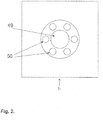
- Fig. 2 shows an arrangement of channels 50 distributed radially around the base of the valve seat 49. The channels 50 are located in the bottom housing 71. The diameter of the channels 50 can be reduced to maximise the support offered to the membrane 2 in Fig 2 , but their number increased to maintain the rate of flow of fluid into the micro valve. An arrangement can be adopted that balances these two competing requirements.
- Fig. 3 shows an alternative arrangement of channels 52 to provide a fluid conduit into the micro valve 100.
- the channels 52 are distributed radially around the base of the valve seat 51.
- the channels 52 are located in the bottom housing 72. It will be clear to those practiced in the art that other arrangements for the channels 52 are possible.
- FIG. 4 shows another embodiment of the micro valve as described in the present invention.
- Fig. 4 shows a valve seat 19 where the tip of the cone has been removed.
- This embodiment can provide an advantage in manufacturing where very small sharp features are often difficult to manufacture with high precision, repeatability, in high numbers and cost effectively. All other aspects of the device shown in Fig. 4 are as described for the device in Fig. 1 .
- the alternative arrangement of the channels 13 are also as described in Fig. 2 and Fig. 3 .
- the membrane is indicated with reference number 11.
- the hole in the membrane has reference number 12.
- the channels in the bottom housing (first body portion) have reference number 13.
- the conduit in the top housing (second body portion) has reference number 14.
- the top housing has reference number 15.
- the bottom housing has reference number 16.
- the chamber between the top housing and membrane has reference number 17.
- the chamber between the bottom housing and membrane has reference number 18.
- the conical valve seat has reference number 19.
- the surface of the conical valve seat has reference number 60.
- the inner periphery of the hole has reference number 61.
- the edge of the inner periphery has reference number 62.
- the mechanical support has reference number 63.
- the surface of the membrane has reference number 64.
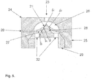
- the micro valve comprises a top housing 24, a bottom housing 25 and a membrane 20 sandwiched between them.
- the bottom housing 25 is further adapted to accept and insert 29.
- the top housing 24 comprises a chamber 26 formed to accommodate the valve seat 28 when the micro valve is assembled.
- the top housing 24 further comprises a channel 23 formed to provide fluid connection to the chamber 26.
- the membrane 20 is formed from elastomeric material and a hole 21 is formed through it.
- the insert 29 is formed to fit into a recess in the bottom housing 25, or to interface mechanically with the bottom housing 25 such that the insert 29 is accurately located relative to the hole 3 in the membrane 20.
- the insert 29 comprises a conical valve seat 28.
- the valve seat protrudes through the hole 21 in the membrane 20. Locating the valve seat 28 into the hole 3 in membrane 20 creates a chamber 27 between the membrane 20 and the insert 29 and bottom housing 25. Channels 22 are formed in the insert 29 to provide fluid flow into chamber 27.
- the surface of the conical valve seat is indicated by reference number 60.
- the inner periphery of the hole has reference number 61.
- the edge of the inner periphery has reference number 62.
- the mechanical support has reference number 63.
- the surface of the membrane has reference number 64.
- micro valve Operation of the micro valve is similar to that described when describing the device in Fig. 1 .
- the parameters that define the breakthrough pressure of the micro valve are also similar to those described for the micro valve shown in Fig. 1 .
- the channels 22 can also be designed according to the alternative designs shown in Fig. 2 and Fig. 3 .
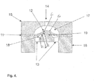
- Fig. 6 shows another embodiment of the micro valve as described in the present invention.
- the micro valve described in Fig. 6 is different from the micro valve described in Fig. 1 with respect to the location of the channels 32 that provide fluid connection to the chamber 37 formed between the membrane 31 and the bottom housing 35.
- the channels 32 are located in a part of the micro valve that does not provide mechanical support for the membrane 31 to prevent it deflecting when the pressure in chamber 36 is higher than the pressure in chamber 37. This allows the design of the micro valve to be optimised to provide the best mechanical support 63 for the membrane 31.
- the micro valve in Fig. 6 also allows the design of chamber 37 to be optimised for fluid flow in chamber 31.
- the hole in the membrane is indicated by reference number 30.
- the conduit in the top housing has reference number 33.
- the top housing has reference number 34.
- the conical valve seat has reference number 38.
- the surface of the conical valve seat has reference number 60.
- the inner periphery of the hole has reference number 61.
- the edge of the inner periphery has reference number 62.
- the mechanical support has reference number 63.
- the surface of the membrane has reference number 64.
- Fig. 7 shows another embodiment of the micro valve described in the present invention.
- the micro valve described in Fig. 7 is different from the micro valve described in Fig. 1 with respect to the location of the channels 42 that provide fluid connection to the chamber 47 formed between the membrane 41 and the bottom housing 45.
- the micro valve shown in Fig. 7 has the advantage that the channels 42 that provide fluid connection to chamber 47 formed between the membrane 41 and the bottom housing 45 are designed to minimise the volume of chamber 47.
- the hole in the membrane is indicated with reference number 40.
- the conduit in the top housing (second body portion) has reference number 43.
- the top housing has reference number 44.
- the chamber between the top housing and membrane has reference number 46.
- the conical valve seat has reference number 48.
- the surface of the conical valve seat has reference number 60.
- the inner periphery of the hole has reference number 61.
- the edge of the inner periphery has reference number 62.
- the mechanical support has reference number 63.
- the surface of the membrane has reference number 64.
Landscapes
- Engineering & Computer Science (AREA)
- General Engineering & Computer Science (AREA)
- Mechanical Engineering (AREA)
- Chemical & Material Sciences (AREA)
- Dispersion Chemistry (AREA)
- Check Valves (AREA)
- Lift Valve (AREA)
Claims (15)
- Dispositif d'administration de médicament comprenant une micro-pompe, ladite micro-pompe comprenant un micro-clapet de retenue (100), caractérisé en ce que le micro-clapet de retenue comprend :un siège de clapet de forme conique (1) etune membrane (2) présentant un orifice (3) qui est situé autour du siège de clapet conique (1), de telle sorte qu'une surface du siège de clapet (1) établit un joint étanche sur une périphérie intérieure de l'orifice prévu dans la membrane (2), et dans lequel, en utilisation, la membrane (2) fléchit par rapport à la surface du siège de clapet pour fournir un passage de fluide à travers la membrane et permette l'écoulement de fluide depuis une face de la membrane vers l'autre face de la membrane, dans lequel le siège de clapet conique (1) fait saillie à travers l'orifice (3) et la surface du siège de clapet (1) établit un joint étanche sur un bord (62) de la périphérie intérieure de l'orifice (3) prévu dans la membrane (2).
- Dispositif d'administration de médicament selon la revendication 1, dans lequel la membrane (2) est un organe flexible qui applique une force sur le siège de clapet (1) lorsque la surface du siège de clapet forme un joint étanche sur la périphérie intérieure de l'orifice prévu dans la membrane.
- Dispositif d'administration de médicament selon l'une quelconque des revendications précédentes, dans lequel le clapet de retenue comprend une face d'entrée et une face de sortie et la membrane (2) est configurée pour fléchir par rapport à la surface du siège de clapet (1) dans le cas d'une différence de pression spécifique entre la face d'entrée et la face de sortie.
- Dispositif d'administration de médicament selon l'une quelconque des revendications précédentes, dans lequel la membrane (2) est supportée, de manière sélective, autour d'une partie périphérique extérieure de la membrane, de telle sorte que le fléchissement est limité à une partie intérieure de la membrane, de préférence dans lequel l'orifice prévu dans la membrane (2) est formé dans la partie intérieure de la membrane.
- Dispositif d'administration de médicament selon l'une quelconque des revendications précédentes, comprenant en outre une première partie de corps qui inclut le siège de clapet.
- Dispositif d'administration de médicament selon la revendication 5, comprenant en outre une butée mécanique (63) pour limiter le fléchissement de la membrane (2) en direction du siège de clapet (1) et de la première partie de corps (7), dans lequel la butée mécanique (63) limite de préférence le fléchissement de la membrane (2) en direction du siège de clapet (1) et de la première partie de corps (7) lorsque la surface du siège de clapet établit un joint étanche sur la périphérie intérieure de l'orifice prévu dans la membrane, et plus de préférence dans lequel la butée mécanique (63) fait partie du siège de clapet (1).
- Dispositif d'administration de médicament selon les revendications 5 et 6, dans lequel la butée mécanique (63) fait partie de la première partie de corps (7).
- Dispositif d'administration de médicament selon l'une quelconque des revendications précédentes et en combinaison avec la revendication 5, dans lequel la première partie de corps (7) possède un conduit de fluide formé pour fournir un orifice d'entrée du clapet de retenue.
- Dispositif d'administration de médicament selon la revendication 8, dans lequel une ouverture est formée au niveau de la base du siège de clapet, laquelle ouverture fait partie du passage de fluide qui traverse la membrane.
- Dispositif d'administration de médicament selon la revendication 8, dans lequel de multiples ouvertures (4) sont formées au niveau de la base du siège de clapet (1), lesquelles ouvertures font partie du passage de fluide qui traverse la membrane (2).
- Dispositif d'administration de médicament selon la revendication 9 ou 10, dans lequel la au moins une ouverture (4) est formée en tant que partie de la butée mécanique (63).
- Dispositif d'administration de médicament selon l'une quelconque des revendications précédentes et en combinaison avec la revendication 5, comprenant en outre une seconde partie de corps (6) sur une face opposée de la membrane (2) par rapport à la première partie de corps (7).
- Dispositif d'administration de médicament selon la revendication 12, dans lequel la seconde partie de corps (6) comprend un conduit de fluide formé à travers celui-ci en définissant une sortie du clapet de retenue.
- Dispositif d'administration de médicament selon les revendications 12 ou 13, dans lequel une cavité (8) est définie par un creux dans la seconde partie de corps (6) dans lequel la membrane (2) se déplace lorsque le clapet s'ouvre, de préférence dans lequel la cavité (8) crée un passage de fluide entre l'orifice prévu dans la membrane (2) et l'orifice de sortie du clapet.
- Dispositif d'administration de médicament selon l'une quelconque des revendications précédentes, dans lequel la membrane (2) est constituée d'un matériau choisi dans un groupe de matériaux comprenant : le caoutchouc, le silicone, et un élastomère.
Priority Applications (1)
| Application Number | Priority Date | Filing Date | Title |
|---|---|---|---|
| EP19157034.0A EP3521669B1 (fr) | 2012-11-22 | 2013-11-21 | Pompe a pulsations munie d'une soupape unidirectionnelle |
Applications Claiming Priority (2)
| Application Number | Priority Date | Filing Date | Title |
|---|---|---|---|
| GBGB1220974.8A GB201220974D0 (en) | 2012-11-22 | 2012-11-22 | Micro valve |
| PCT/NL2013/050839 WO2014081292A1 (fr) | 2012-11-22 | 2013-11-21 | Clapet anti-retour |
Related Child Applications (2)
| Application Number | Title | Priority Date | Filing Date |
|---|---|---|---|
| EP19157034.0A Division-Into EP3521669B1 (fr) | 2012-11-22 | 2013-11-21 | Pompe a pulsations munie d'une soupape unidirectionnelle |
| EP19157034.0A Division EP3521669B1 (fr) | 2012-11-22 | 2013-11-21 | Pompe a pulsations munie d'une soupape unidirectionnelle |
Publications (2)
| Publication Number | Publication Date |
|---|---|
| EP2923123A1 EP2923123A1 (fr) | 2015-09-30 |
| EP2923123B1 true EP2923123B1 (fr) | 2019-06-19 |
Family
ID=47521526
Family Applications (2)
| Application Number | Title | Priority Date | Filing Date |
|---|---|---|---|
| EP13799401.8A Active EP2923123B1 (fr) | 2012-11-22 | 2013-11-21 | Dispositif d'administration de médicament avec microclapet anti-retour |
| EP19157034.0A Active EP3521669B1 (fr) | 2012-11-22 | 2013-11-21 | Pompe a pulsations munie d'une soupape unidirectionnelle |
Family Applications After (1)
| Application Number | Title | Priority Date | Filing Date |
|---|---|---|---|
| EP19157034.0A Active EP3521669B1 (fr) | 2012-11-22 | 2013-11-21 | Pompe a pulsations munie d'une soupape unidirectionnelle |
Country Status (9)
| Country | Link |
|---|---|
| US (2) | US9714716B2 (fr) |
| EP (2) | EP2923123B1 (fr) |
| CN (1) | CN104797869B (fr) |
| AU (1) | AU2013348518B2 (fr) |
| BR (1) | BR112015011689B1 (fr) |
| CA (2) | CA3067596C (fr) |
| GB (1) | GB201220974D0 (fr) |
| RU (1) | RU2645362C2 (fr) |
| WO (1) | WO2014081292A1 (fr) |
Families Citing this family (17)
| Publication number | Priority date | Publication date | Assignee | Title |
|---|---|---|---|---|
| US10790723B2 (en) | 2010-08-24 | 2020-09-29 | Qwtip Llc | Disk-pack turbine |
| WO2013029016A2 (fr) | 2011-08-24 | 2013-02-28 | Qwtip Llc | Éléments de rééquipement à fixer pour systèmes de traitement d'eau |
| US9474991B2 (en) * | 2011-08-24 | 2016-10-25 | Qwtip, Llc | Water treatment system and method |
| US20140183144A1 (en) | 2011-08-24 | 2014-07-03 | Qwtip Llc | Water Treatment System and Method |
| AR093196A1 (es) | 2012-02-28 | 2015-05-27 | Qwtip Llc | Sistema y metodo de desalinizacion y/o produccion de gas |
| AR093197A1 (es) | 2012-02-29 | 2015-05-27 | Qwtip Llc | Sistema y metodo de levitacion y distribucion |
| CN105152371A (zh) * | 2015-09-26 | 2015-12-16 | 胡海平 | 一种带有逆止装置的马鞍座以及一种逆止阀 |
| US10036290B2 (en) | 2016-07-06 | 2018-07-31 | Ford Global Technologies, Llc | Crankcase ventilation valve for an engine |
| CN107448648A (zh) * | 2017-09-25 | 2017-12-08 | 上海应用技术大学 | 一种全塑微型单向阀及其加工方法 |
| WO2019230159A1 (fr) * | 2018-05-31 | 2019-12-05 | 株式会社村田製作所 | Pompe |
| CN109000975A (zh) * | 2018-06-15 | 2018-12-14 | 深圳市水务规划设计院有限公司 | 取水器 |
| CN110201298B (zh) * | 2019-07-03 | 2024-11-15 | 深圳安特医疗股份有限公司 | 单向阀和输液装置 |
| JP7682149B2 (ja) | 2019-07-24 | 2025-05-23 | クエスト メディカル インコーポレイテッド | 濾過式真空リリーフ通気弁 |
| CN111288222A (zh) * | 2020-02-05 | 2020-06-16 | 鲁东大学 | 一种纳米尺度的单向阀结构及其功能的模拟验证方法 |
| CN116326828A (zh) * | 2021-12-24 | 2023-06-27 | 深圳市合元科技有限公司 | 单向阀及电子雾化装置 |
| US12258952B2 (en) | 2023-02-10 | 2025-03-25 | Rochester Institute Of Technology | Leak-free, diffusion-blocking check valve, pump and method |
| WO2024167501A1 (fr) * | 2023-02-10 | 2024-08-15 | Rochester Institute Of Technology | Clapet anti-retour sans fuite à blocage de diffusion, pompe et procédé |
Citations (1)
| Publication number | Priority date | Publication date | Assignee | Title |
|---|---|---|---|---|
| US20070026269A1 (en) * | 2005-07-29 | 2007-02-01 | Canon Kabushiki Kaisha | Relief valve, method of manufacturing relief valve, and fuel cell |
Family Cites Families (21)
| Publication number | Priority date | Publication date | Assignee | Title |
|---|---|---|---|---|
| DE424855C (de) * | 1926-02-03 | Hugo Beyer | Absperrventil mit kegelfoermigem Sitz und Ventilkoerper | |
| US2990849A (en) * | 1956-02-01 | 1961-07-04 | Renault | Non-return valve |
| US3176712A (en) * | 1961-10-03 | 1965-04-06 | Ramsden Clement | Non-return valve |
| US3342208A (en) * | 1963-10-03 | 1967-09-19 | Adam P G Steffes | Resilient material valve |
| US4080981A (en) * | 1976-10-12 | 1978-03-28 | Stewart Anthony F | Antisiphon check valve |
| DE2803778A1 (de) | 1978-01-28 | 1979-08-02 | Freudenberg Carl Fa | Rueckschlagventil |
| IT1234039B (it) * | 1989-03-23 | 1992-04-24 | Ica Spa Bologna Taplas Di Evan | Valvola unidirezionale per fluidi con simultanea garanzia di tenuta contro la penetrazione di fluidi all'esterno, anche senza l'impiego di uno strato viscoso per la membrana elastica e la relativa sede di tenuta |
| DE4241943C2 (de) * | 1992-12-11 | 1994-12-01 | Busak & Luyken Gmbh & Co | Verschlußmittel und Dichtungsventil für Behälteröffnungen |
| US6745763B2 (en) * | 1998-10-27 | 2004-06-08 | Garth T. Webb | Vaporizing device for administering sterile medication |
| DE59909685D1 (de) * | 1999-01-14 | 2004-07-15 | Alstom Technology Ltd Baden | Plattenventil |
| US5971024A (en) | 1999-01-20 | 1999-10-26 | Penny; William H. | Method and apparatus for controlling fluid flow |
| US6651955B2 (en) | 2001-07-30 | 2003-11-25 | Hewlett-Packard Development Company, L.P. | Elastomeric valve, and methods |
| CN100438937C (zh) | 2002-12-30 | 2008-12-03 | 重庆大学 | 一种微型药物释放装置 |
| RU2269052C2 (ru) * | 2003-04-29 | 2006-01-27 | Григорий Григорьевич Халаев | Клапан обратный |
| US7654283B2 (en) | 2003-10-21 | 2010-02-02 | Seiko Epson Corporation | Check valve and pump including check valve |
| CN100447464C (zh) * | 2003-10-21 | 2008-12-31 | 精工爱普生株式会社 | 止回阀及具有止回阀的泵 |
| CN100571810C (zh) | 2004-05-11 | 2009-12-23 | 医疗器械创新有限公司 | 利用流体压力打开和关闭的单向阀 |
| GB2443260C (en) * | 2006-10-26 | 2017-11-29 | Cellnovo Ltd | Micro-valve |
| EP2139539B1 (fr) * | 2007-03-19 | 2021-08-04 | Insuline Medical Ltd. | Procédé et dispositif d'administration de médicament |
| DE202008017031U1 (de) | 2008-12-30 | 2010-05-12 | Neoperl Gmbh | Durchflussmengenregler |
| CN102723914A (zh) | 2012-07-10 | 2012-10-10 | 中国船舶重工集团公司第七二四研究所 | L、s波段超宽带大功率限幅低噪声放大器 |
-
2012
- 2012-11-22 GB GBGB1220974.8A patent/GB201220974D0/en not_active Ceased
-
2013
- 2013-11-21 EP EP13799401.8A patent/EP2923123B1/fr active Active
- 2013-11-21 CN CN201380059940.1A patent/CN104797869B/zh active Active
- 2013-11-21 RU RU2015123999A patent/RU2645362C2/ru active
- 2013-11-21 BR BR112015011689-2A patent/BR112015011689B1/pt active IP Right Grant
- 2013-11-21 WO PCT/NL2013/050839 patent/WO2014081292A1/fr not_active Ceased
- 2013-11-21 CA CA3067596A patent/CA3067596C/fr active Active
- 2013-11-21 CA CA2889806A patent/CA2889806C/fr active Active
- 2013-11-21 US US14/436,607 patent/US9714716B2/en active Active
- 2013-11-21 EP EP19157034.0A patent/EP3521669B1/fr active Active
- 2013-11-21 AU AU2013348518A patent/AU2013348518B2/en active Active
-
2017
- 2017-06-20 US US15/628,380 patent/US10502331B2/en active Active
Patent Citations (1)
| Publication number | Priority date | Publication date | Assignee | Title |
|---|---|---|---|---|
| US20070026269A1 (en) * | 2005-07-29 | 2007-02-01 | Canon Kabushiki Kaisha | Relief valve, method of manufacturing relief valve, and fuel cell |
Also Published As
| Publication number | Publication date |
|---|---|
| CA2889806C (fr) | 2020-06-16 |
| CN104797869A (zh) | 2015-07-22 |
| US9714716B2 (en) | 2017-07-25 |
| RU2015123999A (ru) | 2017-01-10 |
| EP2923123A1 (fr) | 2015-09-30 |
| US20150276073A1 (en) | 2015-10-01 |
| CA3067596A1 (fr) | 2014-05-30 |
| CN104797869B (zh) | 2018-02-16 |
| BR112015011689A2 (pt) | 2017-07-11 |
| AU2013348518B2 (en) | 2017-11-16 |
| EP3521669B1 (fr) | 2021-10-20 |
| WO2014081292A1 (fr) | 2014-05-30 |
| AU2013348518A1 (en) | 2015-05-14 |
| EP3521669A1 (fr) | 2019-08-07 |
| CA3067596C (fr) | 2022-06-28 |
| CA2889806A1 (fr) | 2014-05-30 |
| GB201220974D0 (en) | 2013-01-02 |
| US20170299075A1 (en) | 2017-10-19 |
| RU2645362C2 (ru) | 2018-02-21 |
| US10502331B2 (en) | 2019-12-10 |
| BR112015011689B1 (pt) | 2022-05-03 |
Similar Documents
| Publication | Publication Date | Title |
|---|---|---|
| EP2923123B1 (fr) | Dispositif d'administration de médicament avec microclapet anti-retour | |
| US10054234B2 (en) | One-way valve | |
| CA2667528C (fr) | Microvalve | |
| JP6450687B2 (ja) | ダイヤフラム逆止弁およびその製造方法 | |
| US10240689B2 (en) | Diaphragm check valves and methods of manufacture thereof | |
| AU2007310633B2 (en) | Micro-valve |
Legal Events
| Date | Code | Title | Description |
|---|---|---|---|
| PUAI | Public reference made under article 153(3) epc to a published international application that has entered the european phase |
Free format text: ORIGINAL CODE: 0009012 |
|
| 17P | Request for examination filed |
Effective date: 20150423 |
|
| AK | Designated contracting states |
Kind code of ref document: A1 Designated state(s): AL AT BE BG CH CY CZ DE DK EE ES FI FR GB GR HR HU IE IS IT LI LT LU LV MC MK MT NL NO PL PT RO RS SE SI SK SM TR |
|
| AX | Request for extension of the european patent |
Extension state: BA ME |
|
| DAX | Request for extension of the european patent (deleted) | ||
| STAA | Information on the status of an ep patent application or granted ep patent |
Free format text: STATUS: EXAMINATION IS IN PROGRESS |
|
| 17Q | First examination report despatched |
Effective date: 20170519 |
|
| GRAP | Despatch of communication of intention to grant a patent |
Free format text: ORIGINAL CODE: EPIDOSNIGR1 |
|
| STAA | Information on the status of an ep patent application or granted ep patent |
Free format text: STATUS: GRANT OF PATENT IS INTENDED |
|
| INTG | Intention to grant announced |
Effective date: 20181010 |
|
| GRAJ | Information related to disapproval of communication of intention to grant by the applicant or resumption of examination proceedings by the epo deleted |
Free format text: ORIGINAL CODE: EPIDOSDIGR1 |
|
| STAA | Information on the status of an ep patent application or granted ep patent |
Free format text: STATUS: EXAMINATION IS IN PROGRESS |
|
| GRAP | Despatch of communication of intention to grant a patent |
Free format text: ORIGINAL CODE: EPIDOSNIGR1 |
|
| STAA | Information on the status of an ep patent application or granted ep patent |
Free format text: STATUS: GRANT OF PATENT IS INTENDED |
|
| INTC | Intention to grant announced (deleted) | ||
| INTG | Intention to grant announced |
Effective date: 20190111 |
|
| GRAS | Grant fee paid |
Free format text: ORIGINAL CODE: EPIDOSNIGR3 |
|
| GRAA | (expected) grant |
Free format text: ORIGINAL CODE: 0009210 |
|
| STAA | Information on the status of an ep patent application or granted ep patent |
Free format text: STATUS: THE PATENT HAS BEEN GRANTED |
|
| AK | Designated contracting states |
Kind code of ref document: B1 Designated state(s): AL AT BE BG CH CY CZ DE DK EE ES FI FR GB GR HR HU IE IS IT LI LT LU LV MC MK MT NL NO PL PT RO RS SE SI SK SM TR |
|
| REG | Reference to a national code |
Ref country code: GB Ref legal event code: FG4D |
|
| REG | Reference to a national code |
Ref country code: CH Ref legal event code: EP |
|
| REG | Reference to a national code |
Ref country code: IE Ref legal event code: FG4D |
|
| REG | Reference to a national code |
Ref country code: DE Ref legal event code: R096 Ref document number: 602013056863 Country of ref document: DE |
|
| REG | Reference to a national code |
Ref country code: AT Ref legal event code: REF Ref document number: 1145955 Country of ref document: AT Kind code of ref document: T Effective date: 20190715 |
|
| REG | Reference to a national code |
Ref country code: NL Ref legal event code: FP |
|
| REG | Reference to a national code |
Ref country code: SE Ref legal event code: TRGR |
|
| PG25 | Lapsed in a contracting state [announced via postgrant information from national office to epo] |
Ref country code: FI Free format text: LAPSE BECAUSE OF FAILURE TO SUBMIT A TRANSLATION OF THE DESCRIPTION OR TO PAY THE FEE WITHIN THE PRESCRIBED TIME-LIMIT Effective date: 20190619 Ref country code: NO Free format text: LAPSE BECAUSE OF FAILURE TO SUBMIT A TRANSLATION OF THE DESCRIPTION OR TO PAY THE FEE WITHIN THE PRESCRIBED TIME-LIMIT Effective date: 20190919 Ref country code: LT Free format text: LAPSE BECAUSE OF FAILURE TO SUBMIT A TRANSLATION OF THE DESCRIPTION OR TO PAY THE FEE WITHIN THE PRESCRIBED TIME-LIMIT Effective date: 20190619 Ref country code: HR Free format text: LAPSE BECAUSE OF FAILURE TO SUBMIT A TRANSLATION OF THE DESCRIPTION OR TO PAY THE FEE WITHIN THE PRESCRIBED TIME-LIMIT Effective date: 20190619 Ref country code: AL Free format text: LAPSE BECAUSE OF FAILURE TO SUBMIT A TRANSLATION OF THE DESCRIPTION OR TO PAY THE FEE WITHIN THE PRESCRIBED TIME-LIMIT Effective date: 20190619 |
|
| REG | Reference to a national code |
Ref country code: LT Ref legal event code: MG4D |
|
| PG25 | Lapsed in a contracting state [announced via postgrant information from national office to epo] |
Ref country code: LV Free format text: LAPSE BECAUSE OF FAILURE TO SUBMIT A TRANSLATION OF THE DESCRIPTION OR TO PAY THE FEE WITHIN THE PRESCRIBED TIME-LIMIT Effective date: 20190619 Ref country code: RS Free format text: LAPSE BECAUSE OF FAILURE TO SUBMIT A TRANSLATION OF THE DESCRIPTION OR TO PAY THE FEE WITHIN THE PRESCRIBED TIME-LIMIT Effective date: 20190619 Ref country code: BG Free format text: LAPSE BECAUSE OF FAILURE TO SUBMIT A TRANSLATION OF THE DESCRIPTION OR TO PAY THE FEE WITHIN THE PRESCRIBED TIME-LIMIT Effective date: 20190919 Ref country code: GR Free format text: LAPSE BECAUSE OF FAILURE TO SUBMIT A TRANSLATION OF THE DESCRIPTION OR TO PAY THE FEE WITHIN THE PRESCRIBED TIME-LIMIT Effective date: 20190920 |
|
| REG | Reference to a national code |
Ref country code: AT Ref legal event code: MK05 Ref document number: 1145955 Country of ref document: AT Kind code of ref document: T Effective date: 20190619 |
|
| PG25 | Lapsed in a contracting state [announced via postgrant information from national office to epo] |
Ref country code: SK Free format text: LAPSE BECAUSE OF FAILURE TO SUBMIT A TRANSLATION OF THE DESCRIPTION OR TO PAY THE FEE WITHIN THE PRESCRIBED TIME-LIMIT Effective date: 20190619 Ref country code: CZ Free format text: LAPSE BECAUSE OF FAILURE TO SUBMIT A TRANSLATION OF THE DESCRIPTION OR TO PAY THE FEE WITHIN THE PRESCRIBED TIME-LIMIT Effective date: 20190619 Ref country code: RO Free format text: LAPSE BECAUSE OF FAILURE TO SUBMIT A TRANSLATION OF THE DESCRIPTION OR TO PAY THE FEE WITHIN THE PRESCRIBED TIME-LIMIT Effective date: 20190619 Ref country code: AT Free format text: LAPSE BECAUSE OF FAILURE TO SUBMIT A TRANSLATION OF THE DESCRIPTION OR TO PAY THE FEE WITHIN THE PRESCRIBED TIME-LIMIT Effective date: 20190619 Ref country code: EE Free format text: LAPSE BECAUSE OF FAILURE TO SUBMIT A TRANSLATION OF THE DESCRIPTION OR TO PAY THE FEE WITHIN THE PRESCRIBED TIME-LIMIT Effective date: 20190619 Ref country code: PT Free format text: LAPSE BECAUSE OF FAILURE TO SUBMIT A TRANSLATION OF THE DESCRIPTION OR TO PAY THE FEE WITHIN THE PRESCRIBED TIME-LIMIT Effective date: 20191021 |
|
| REG | Reference to a national code |
Ref country code: NL Ref legal event code: RC Free format text: DETAILS LICENCE OR PLEDGE: RIGHT OF PLEDGE, ESTABLISHED, 1E RANG Name of requester: DE STAAT DER NEDERLANDEN Effective date: 20200204 |
|
| PG25 | Lapsed in a contracting state [announced via postgrant information from national office to epo] |
Ref country code: IT Free format text: LAPSE BECAUSE OF FAILURE TO SUBMIT A TRANSLATION OF THE DESCRIPTION OR TO PAY THE FEE WITHIN THE PRESCRIBED TIME-LIMIT Effective date: 20190619 Ref country code: SM Free format text: LAPSE BECAUSE OF FAILURE TO SUBMIT A TRANSLATION OF THE DESCRIPTION OR TO PAY THE FEE WITHIN THE PRESCRIBED TIME-LIMIT Effective date: 20190619 Ref country code: ES Free format text: LAPSE BECAUSE OF FAILURE TO SUBMIT A TRANSLATION OF THE DESCRIPTION OR TO PAY THE FEE WITHIN THE PRESCRIBED TIME-LIMIT Effective date: 20190619 Ref country code: IS Free format text: LAPSE BECAUSE OF FAILURE TO SUBMIT A TRANSLATION OF THE DESCRIPTION OR TO PAY THE FEE WITHIN THE PRESCRIBED TIME-LIMIT Effective date: 20191019 |
|
| PG25 | Lapsed in a contracting state [announced via postgrant information from national office to epo] |
Ref country code: TR Free format text: LAPSE BECAUSE OF FAILURE TO SUBMIT A TRANSLATION OF THE DESCRIPTION OR TO PAY THE FEE WITHIN THE PRESCRIBED TIME-LIMIT Effective date: 20190619 |
|
| PG25 | Lapsed in a contracting state [announced via postgrant information from national office to epo] |
Ref country code: PL Free format text: LAPSE BECAUSE OF FAILURE TO SUBMIT A TRANSLATION OF THE DESCRIPTION OR TO PAY THE FEE WITHIN THE PRESCRIBED TIME-LIMIT Effective date: 20190619 Ref country code: DK Free format text: LAPSE BECAUSE OF FAILURE TO SUBMIT A TRANSLATION OF THE DESCRIPTION OR TO PAY THE FEE WITHIN THE PRESCRIBED TIME-LIMIT Effective date: 20190619 |
|
| PG25 | Lapsed in a contracting state [announced via postgrant information from national office to epo] |
Ref country code: IS Free format text: LAPSE BECAUSE OF FAILURE TO SUBMIT A TRANSLATION OF THE DESCRIPTION OR TO PAY THE FEE WITHIN THE PRESCRIBED TIME-LIMIT Effective date: 20200224 |
|
| REG | Reference to a national code |
Ref country code: DE Ref legal event code: R097 Ref document number: 602013056863 Country of ref document: DE |
|
| REG | Reference to a national code |
Ref country code: CH Ref legal event code: PL |
|
| PLBE | No opposition filed within time limit |
Free format text: ORIGINAL CODE: 0009261 |
|
| STAA | Information on the status of an ep patent application or granted ep patent |
Free format text: STATUS: NO OPPOSITION FILED WITHIN TIME LIMIT |
|
| PG2D | Information on lapse in contracting state deleted |
Ref country code: IS |
|
| PG25 | Lapsed in a contracting state [announced via postgrant information from national office to epo] |
Ref country code: LU Free format text: LAPSE BECAUSE OF NON-PAYMENT OF DUE FEES Effective date: 20191121 Ref country code: MC Free format text: LAPSE BECAUSE OF FAILURE TO SUBMIT A TRANSLATION OF THE DESCRIPTION OR TO PAY THE FEE WITHIN THE PRESCRIBED TIME-LIMIT Effective date: 20190619 Ref country code: LI Free format text: LAPSE BECAUSE OF NON-PAYMENT OF DUE FEES Effective date: 20191130 Ref country code: CH Free format text: LAPSE BECAUSE OF NON-PAYMENT OF DUE FEES Effective date: 20191130 |
|
| 26N | No opposition filed |
Effective date: 20200603 |
|
| REG | Reference to a national code |
Ref country code: BE Ref legal event code: MM Effective date: 20191130 |
|
| PG25 | Lapsed in a contracting state [announced via postgrant information from national office to epo] |
Ref country code: SI Free format text: LAPSE BECAUSE OF FAILURE TO SUBMIT A TRANSLATION OF THE DESCRIPTION OR TO PAY THE FEE WITHIN THE PRESCRIBED TIME-LIMIT Effective date: 20190619 |
|
| PG25 | Lapsed in a contracting state [announced via postgrant information from national office to epo] |
Ref country code: IE Free format text: LAPSE BECAUSE OF NON-PAYMENT OF DUE FEES Effective date: 20191121 |
|
| PG25 | Lapsed in a contracting state [announced via postgrant information from national office to epo] |
Ref country code: BE Free format text: LAPSE BECAUSE OF NON-PAYMENT OF DUE FEES Effective date: 20191130 |
|
| PG25 | Lapsed in a contracting state [announced via postgrant information from national office to epo] |
Ref country code: CY Free format text: LAPSE BECAUSE OF FAILURE TO SUBMIT A TRANSLATION OF THE DESCRIPTION OR TO PAY THE FEE WITHIN THE PRESCRIBED TIME-LIMIT Effective date: 20190619 |
|
| PG25 | Lapsed in a contracting state [announced via postgrant information from national office to epo] |
Ref country code: MT Free format text: LAPSE BECAUSE OF FAILURE TO SUBMIT A TRANSLATION OF THE DESCRIPTION OR TO PAY THE FEE WITHIN THE PRESCRIBED TIME-LIMIT Effective date: 20190619 Ref country code: HU Free format text: LAPSE BECAUSE OF FAILURE TO SUBMIT A TRANSLATION OF THE DESCRIPTION OR TO PAY THE FEE WITHIN THE PRESCRIBED TIME-LIMIT; INVALID AB INITIO Effective date: 20131121 |
|
| PG25 | Lapsed in a contracting state [announced via postgrant information from national office to epo] |
Ref country code: MK Free format text: LAPSE BECAUSE OF FAILURE TO SUBMIT A TRANSLATION OF THE DESCRIPTION OR TO PAY THE FEE WITHIN THE PRESCRIBED TIME-LIMIT Effective date: 20190619 |
|
| PGFP | Annual fee paid to national office [announced via postgrant information from national office to epo] |
Ref country code: NL Payment date: 20251119 Year of fee payment: 13 |
|
| PGFP | Annual fee paid to national office [announced via postgrant information from national office to epo] |
Ref country code: DE Payment date: 20251119 Year of fee payment: 13 |
|
| PGFP | Annual fee paid to national office [announced via postgrant information from national office to epo] |
Ref country code: GB Payment date: 20251114 Year of fee payment: 13 |
|
| PGFP | Annual fee paid to national office [announced via postgrant information from national office to epo] |
Ref country code: FR Payment date: 20251125 Year of fee payment: 13 |
|
| PGFP | Annual fee paid to national office [announced via postgrant information from national office to epo] |
Ref country code: SE Payment date: 20251119 Year of fee payment: 13 |