EP2923442B1 - Systèmes et procédés pour l'adaptation limitée en bande de linéarisation d'ap - Google Patents
Systèmes et procédés pour l'adaptation limitée en bande de linéarisation d'ap Download PDFInfo
- Publication number
- EP2923442B1 EP2923442B1 EP13802117.5A EP13802117A EP2923442B1 EP 2923442 B1 EP2923442 B1 EP 2923442B1 EP 13802117 A EP13802117 A EP 13802117A EP 2923442 B1 EP2923442 B1 EP 2923442B1
- Authority
- EP
- European Patent Office
- Prior art keywords
- band
- limited
- power amplifier
- bandwidth
- signal
- Prior art date
- Legal status (The legal status is an assumption and is not a legal conclusion. Google has not performed a legal analysis and makes no representation as to the accuracy of the status listed.)
- Not-in-force
Links
- 230000006978 adaptation Effects 0.000 title claims description 73
- 238000000034 method Methods 0.000 title claims description 37
- 230000008569 process Effects 0.000 claims description 9
- 238000012545 processing Methods 0.000 claims description 6
- 230000006870 function Effects 0.000 description 34
- 238000005070 sampling Methods 0.000 description 31
- 238000004088 simulation Methods 0.000 description 24
- 238000013459 approach Methods 0.000 description 6
- 230000002238 attenuated effect Effects 0.000 description 6
- 230000003446 memory effect Effects 0.000 description 5
- 230000004044 response Effects 0.000 description 5
- 238000004891 communication Methods 0.000 description 3
- 238000013461 design Methods 0.000 description 3
- 230000006872 improvement Effects 0.000 description 3
- 238000001228 spectrum Methods 0.000 description 3
- 230000000694 effects Effects 0.000 description 2
- 238000012986 modification Methods 0.000 description 2
- 230000004048 modification Effects 0.000 description 2
- 230000003595 spectral effect Effects 0.000 description 2
- 230000006399 behavior Effects 0.000 description 1
- 230000008901 benefit Effects 0.000 description 1
- 230000015556 catabolic process Effects 0.000 description 1
- 230000010267 cellular communication Effects 0.000 description 1
- 230000001149 cognitive effect Effects 0.000 description 1
- 238000006731 degradation reaction Methods 0.000 description 1
- 230000001419 dependent effect Effects 0.000 description 1
- 238000011161 development Methods 0.000 description 1
- 230000018109 developmental process Effects 0.000 description 1
- 230000009977 dual effect Effects 0.000 description 1
- 238000001914 filtration Methods 0.000 description 1
- 230000009467 reduction Effects 0.000 description 1
Images







Classifications
-
- H—ELECTRICITY
- H03—ELECTRONIC CIRCUITRY
- H03F—AMPLIFIERS
- H03F1/00—Details of amplifiers with only discharge tubes, only semiconductor devices or only unspecified devices as amplifying elements
- H03F1/32—Modifications of amplifiers to reduce non-linear distortion
- H03F1/3241—Modifications of amplifiers to reduce non-linear distortion using predistortion circuits
- H03F1/3258—Modifications of amplifiers to reduce non-linear distortion using predistortion circuits based on polynomial terms
-
- H—ELECTRICITY
- H03—ELECTRONIC CIRCUITRY
- H03F—AMPLIFIERS
- H03F1/00—Details of amplifiers with only discharge tubes, only semiconductor devices or only unspecified devices as amplifying elements
- H03F1/32—Modifications of amplifiers to reduce non-linear distortion
- H03F1/3241—Modifications of amplifiers to reduce non-linear distortion using predistortion circuits
- H03F1/3247—Modifications of amplifiers to reduce non-linear distortion using predistortion circuits using feedback acting on predistortion circuits
-
- H—ELECTRICITY
- H03—ELECTRONIC CIRCUITRY
- H03F—AMPLIFIERS
- H03F1/00—Details of amplifiers with only discharge tubes, only semiconductor devices or only unspecified devices as amplifying elements
- H03F1/34—Negative-feedback-circuit arrangements with or without positive feedback
-
- H—ELECTRICITY
- H03—ELECTRONIC CIRCUITRY
- H03F—AMPLIFIERS
- H03F3/00—Amplifiers with only discharge tubes or only semiconductor devices as amplifying elements
- H03F3/20—Power amplifiers, e.g. Class B amplifiers, Class C amplifiers
- H03F3/24—Power amplifiers, e.g. Class B amplifiers, Class C amplifiers of transmitter output stages
-
- H—ELECTRICITY
- H04—ELECTRIC COMMUNICATION TECHNIQUE
- H04L—TRANSMISSION OF DIGITAL INFORMATION, e.g. TELEGRAPHIC COMMUNICATION
- H04L27/00—Modulated-carrier systems
- H04L27/32—Carrier systems characterised by combinations of two or more of the types covered by groups H04L27/02, H04L27/10, H04L27/18 or H04L27/26
- H04L27/34—Amplitude- and phase-modulated carrier systems, e.g. quadrature-amplitude modulated carrier systems
- H04L27/36—Modulator circuits; Transmitter circuits
- H04L27/366—Arrangements for compensating undesirable properties of the transmission path between the modulator and the demodulator
- H04L27/367—Arrangements for compensating undesirable properties of the transmission path between the modulator and the demodulator using predistortion
- H04L27/368—Arrangements for compensating undesirable properties of the transmission path between the modulator and the demodulator using predistortion adaptive predistortion
-
- H—ELECTRICITY
- H03—ELECTRONIC CIRCUITRY
- H03F—AMPLIFIERS
- H03F2200/00—Indexing scheme relating to amplifiers
- H03F2200/111—Indexing scheme relating to amplifiers the amplifier being a dual or triple band amplifier, e.g. 900 and 1800 MHz, e.g. switched or not switched, simultaneously or not
-
- H—ELECTRICITY
- H04—ELECTRIC COMMUNICATION TECHNIQUE
- H04B—TRANSMISSION
- H04B1/00—Details of transmission systems, not covered by a single one of groups H04B3/00 - H04B13/00; Details of transmission systems not characterised by the medium used for transmission
- H04B1/02—Transmitters
- H04B1/04—Circuits
- H04B2001/0408—Circuits with power amplifiers
- H04B2001/0433—Circuits with power amplifiers with linearisation using feedback
Definitions
- the present disclosure relates to a digital predistortion system that compensates for non-linearities of a power amplifier and more particularly relates to a digital predistortion system that compensates for non-linearities of a power amplifier where the digital predistortion system includes a band-limited adaptation subsystem.
- PAs power amplifiers
- the response of the power amplifier at or near the point of saturation is non-linear.
- an output response of a power amplifier is non-linear and exhibits memory effects when the power amplifier is operating in the power amplifier's high-efficiency range.
- One way to improve the efficiency and overall linearity of a power amplifier is to digitally predistort the input to the power amplifier to compensate for the distortion introduced by the power amplifier.
- the input signal is adjusted in anticipation of the distortion to be introduced by the power amplifier such that the output signal of the power amplifier is substantially free of distortion products.
- digital predistortion is applied to the input signal at baseband frequencies, i.e., before the input signal is up-converted to a desired radio frequency.
- the function f NL-IM3 is the response of the power amplifier to the input x and the subscript NL-IM3 denotes non-linearity up to order three.
- FIG. 1 illustrates a conventional system 10 that implements this digital predistortion approach to compensate for non-linearities of a power amplifier 12.
- a baseband (BB) source 14 outputs a baseband signal, which is up-sampled by up-sampling circuitry 16 in provision for bandwidth expansion that occurs inside a predistorter (PD) 18.
- the predistorter 18 predistorts the up-sampled baseband input signal to provide a predistorted baseband input signal.
- the predistortion, or non-linearities, introduced by the predistorter 18 compensates for the non-linearities of the power amplifier 12.
- the predistorted baseband signal is then upconverted to a desired carrier frequency ( ⁇ C ) and then quadrature modulated by an upconverter 20 and quadrature modulator 22, respectively.
- the upconverted and quadrature modulated predistorted input signal is then converted from digital to analog by a digital-to-analog converter (DAC) 24 to thereby provide a power amplifier input signal.
- the power amplifier input signal is then amplified by the power amplifier 12. Again, the predistortion introduced by the predistorter 18 compensates, or effectively cancels, the distortion caused by non-linearities of the power amplifier 12.
- the power amplifier output signal is fed back into an observation receiver 26.
- the observation receiver 26 includes a wideband filter 30, an attenuator 32, downconversion and demodulation circuitry 34, and an analog-to-digital converter (ADC) 36 arranged as shown.
- the output of the observation receiver 26 is referred to herein as an observation signal (S O ).
- An adaptor 28 then adaptively configures the predistorter 18 based on a comparison of time-aligned as well as gain and phase adjusted versions of the observation signal (S O ) and a reference signal (S R ), which in this case is the up-sampled input signal input into the predistorter 18.
- the adaptor 28 configures the coefficients of the predistorter 18 based on the comparison of the time-aligned as well as gain and phase adjusted versions of the observation signal (S O ) and the reference signal (S R ).
- the predistorter 18, the observation receiver 26, and the adaptor 28 are referred to herein as a digital predistortion (DPD) system 38 whereas the observation receiver 26 and the adaptor 28 are referred to herein as an adaptation subsystem 40 of the digital predistortion system 38.
- DPD digital predistortion
- the non-linearities of the power amplifier 12 result in bandwidth expansion which in turn results in increased sampling rate requirements for the predistorter 18 and the adaptor 28. More specifically, as illustrated in Figure 2 , the reference signal (S R ) has a bandwidth (B). In contrast, as a result of both predistortion and the non-linearities of the power amplifier 12, the observation signal (S O ) suffers from bandwidth expansion.
- the bandwidth expansion is equal to N MAX_ORDER times B, where N MAX_ORDER is the maximum order of non-linearities of the power amplifier 12 for which the digital predistortion subsystem 38 is designed to compensate.
- fifth-order non-linearities for example, cause the spectrum of the observation signal (S O ) to occupy five times the bandwidth (B) of the reference signal (S R ).
- the digital predistortion system 38, and in particular the adaptation subsystem 40 is designed to support a bandwidth of five times the bandwidth (B) of the reference signal (S R ) (i.e., 5xB).
- the wideband filter 30 is designed such that a bandwidth of the pass-band of the wideband filter 30 is five times the bandwidth (B) of the reference signal (S R ).
- the sampling rate of the adaptor 28 is therefore greater than five times the bandwidth (B) of the reference signal (S R ).
- the digital predistortion system 38 and in particular the adaptation subsystem 40, must support a much larger bandwidth. These very large bandwidths are challenging for hardware implementations. Further, even if hardware can be designed to support these wide bandwidths, the resulting hardware requires a significant amount of resources and power. As such, there is a need for an adaptation subsystem for a digital predistortion system that minimizes, or substantially reduces, resource and/or power requirements.
- the PD reduces the spectral regrowth of the fundamental signal at the carrier frequency ( ⁇ o ) and removes the harmonics (2 ⁇ ⁇ , 3 ⁇ ⁇ , ⁇ ) at the same time.
- the PD structure is composed of multiple predistorters (PDs) centered at integer multiples of ⁇ o .
- the PD at ⁇ o is for removing spectral regrowth of the fundamental signal, and the others are for harmonic reduction.
- parameters of PDs are found jointly.
- Document US 2012/128099 A1 may be construed to disclose a technique pertaining to pre-distorted transmitters operable over a wide range of frequencies including a plurality of predetermined frequency bands.
- the transmitters include a programmable digital up-converter and a programmable digital down-converter, an ADC, a DAC, a power amplifier and at least one analog filter arranged along a transmit signal path and a feedback signal path.
- a system in one example, includes a power amplifier configured to amplify a power amplifier input signal to provide a power amplifier output signal and a digital predistortion system configured to compensate for up to a predefined maximum order of non-linearity of the power amplifier.
- the digital predistortion system includes a band-limited adaptation subsystem. As compared to conventional adaptation subsystems, the band-limited adaptation subsystem is significantly less complex and consumes less power.
- the power amplifier output signal is a single-band signal
- the band-limited adaptation subsystem observes a bandwidth that is less than N MAX_ORDER times a desired bandwidth of the power amplifier output signal, where N MAX_ORDER is the predefined maximum order of non-linearity of the power amplifier for which the digital predistortion system compensates.
- the bandwidth observed by the band-limited adaptation subsystem is in a range of and including 1.5 to 2 times the desired bandwidth of the power amplifier output signal.
- the predefined maximum order of non-linearity of the power amplifier for which the digital predistortion system compensates is preferably greater than or equal to third-order such that the digital predistortion system compensates for up to at least the third-order non-linearities of the power amplifier.
- the predefined maximum order of non-linearity of the power amplifier for which the digital predistortion system compensates is preferably greater than or equal to fifth-order such that the digital predistortion system compensates for up to at least the fifth-order non-linearities of the power amplifier.
- the power amplifier output signal is a concurrent multi-band signal having multiple frequency bands and, for each frequency band of the power amplifier output signal, the band-limited adaptation subsystem observes a bandwidth that is less than N MAX_ORDER times a desired bandwidth of the frequency band, wherein N MAX_ORDER is the predefined maximum order of non-linearity of the power amplifier for which the digital predistortion system compensates.
- N MAX_ORDER is the predefined maximum order of non-linearity of the power amplifier for which the digital predistortion system compensates.
- the bandwidth observed by the band-limited adaptation subsystem is in a range of and including 1.5 to 2 times the desired bandwidth of the frequency band.
- the predefined maximum order of non-linearity of the power amplifier for which the digital predistortion system compensates is preferably greater than or equal to third-order such that the digital predistortion system compensates for up to at least the third-order non-linearities of the power amplifier.
- the predefined maximum order of non-linearity of the power amplifier for which the digital predistortion system compensates is preferably greater than or equal to fifth-order such that the digital predistortion system compensates for up to at least the fifth-order non-linearities of the power amplifier.
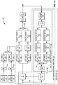
- Figure 4 illustrates a system 42 including a digital predistortion (DPD) system 44 that compensates for non-linearities of a power amplifier (PA) 46 according to one embodiment of the present disclosure.
- the digital predistortion system 44 includes a predistorter (PD) 48 and a band-limited adaptation subsystem 50, where the band-limited adaptation subsystem 50 includes a band-limited observation receiver 52 and an adaptor 54 arranged as shown.
- the band-limited observation receiver 52 includes a band-limiting function such that a bandwidth observed by the band-limited observation receiver 52, and thus the band-limited adaptation subsystem 50, is less than N MAX_ORDER times a bandwidth of an input signal to the predistorter 48, where N MAX_ORDER is a maximum order of non-linearity of the power amplifier 46 for which the digital predistortion system 44 is designed to compensate.
- the bandwidth observed by the band-limited observation receiver 52 is also referred to herein as the bandwidth supported by the band-limited adaptation subsystem 50 as well as the bandwidth supported by the band-limited observation receiver 52.
- the bandwidth of the input signal to the predistorter 48 is also a desired bandwidth of a power amplifier output signal output by the power amplifier 46.
- the bandwidth observed by the band-limited observation receiver 52, and thus the band-limited adaptation subsystem 50 is in a range of and including 1.5 to 2 times the bandwidth of the input signal to the predistorter 48 (i.e., the bandwidth of reference signal (S R ) and thus the desired bandwidth of the power amplifier output signal).
- a baseband (BB) source 56 generates a baseband input signal, which is up-sampled by up-sampling circuitry 58 to a desired sampling rate.
- the desired sampling rate is greater than N MAX_ORDER xB, where B is a bandwidth of the baseband input signal.
- the bandwidth B is also a bandwidth of the reference signal (S R ) and a desired bandwidth of a power amplifier output signal output by the power amplifier 46.
- the predistorter 48 predistorts the up-sampled baseband input signal to provide a predistorted baseband input signal.
- the predistortion introduced by the predistorter 48 compensates for up to the maximum order of non-linearity of the power amplifier 46 for which the digital predistortion system 44 is designed to compensate (N MAX_ORDER ).
- the maximum order of non-linearity of the power amplifier 46 for which the digital predistortion system 44 is designed to compensate is at least the third-order. In one preferred embodiment, the maximum order of non-linearity of the power amplifier 46 for which the digital predistortion system 44 is designed to compensate is the fifth-order.
- the predistorted baseband input signal is then upconverted and quadrature modulated by an upconverter 60 and a quadrature modulator 62, respectively.
- the resulting upconverted, modulated, and predistorted input signal is then converted from digital to analog by a digital-to-analog converter (DAC) 64 to thereby provide a power amplifier input signal.
- DAC digital-to-analog converter
- the DAC 64 is illustrated as being between the quadrature modulator 62 and the power amplifier 46 in this embodiment, the location of the DAC 64 may vary depending on the particular implementation.
- the power amplifier 46 amplifies the power amplifier input signal to provide the power amplifier output signal.
- the power amplifier output signal is fed back into the band-limited observation receiver 52.
- the band-limited adaptation subsystem 50 and in particular the band-limited observation receiver 52, introduces a band-limiting function that significantly reduces an observation bandwidth of the band-limited observation receiver 52 and thus a sampling rate requirement of the adaptor 54.
- the bandwidth observed by the band-limited observation receiver 52 is denoted as B LlMITED .
- the bandwidth (B LIMITED ) observed by the band-limited observation receiver 52 is less than N MAX_ORDER xB and, in one preferred embodiment, is in a range of and including 1.5 to 2 times B.
- the sampling rate requirement for the adaptor 54 is reduced from greater than N MAX_ORDER xB for the conventional digital predistortion system 10 ( Figure 1 ) to greater than B LIMITED .
- the sampling rate requirement for the adaptor 54 is reduced from 200 MHz to less than 200 MHz and, in one preferred embodiment, 60 MHz to 80 MHz.
- the band-limited observation receiver 52 includes a narrowband filter 66, an attenuator 68, downconversion and demodulation circuitry 70, and an analog-to-digital converter (ADC) 72 arranged as shown.
- the output of the band-limited observation receiver 52 is referred to herein as a band-limited observation signal (S O-BL ).
- the narrowband filter 66 serves as the band-limiting function of the band-limited observation receiver 52.
- the narrowband filter 66 has a pass-band that includes the desired frequency band of the power amplifier output signal (e.g., centered at the carrier frequency of the power amplifier output signal), and a bandwidth of the pass-band of the narrowband filter 66 is less than N MAX_ORDER times the desired bandwidth of the power amplifier output signal (i.e., less than N MAX_ORDER xB).
- the bandwidth of the pass-band of the narrowband filter 66 is less than two times, and more preferably in a range of and including 1.5 to 2 times, the desired bandwidth of the power amplifier output signal, where N MAX_ORDER is greater than or equal to 3 or more preferably greater than or equal to 5.
- the bandwidth (B LIMITED ) observed by the band-limited observation receiver 52 is significantly less than the bandwidth observed by the conventional observation receiver 26 described above with respect to Figure 1 .
- the adaptor 54 and the ADC 72 are enabled to run at significantly lower sampling rates.
- the narrowband filter 66 filters the power amplifier output signal to provide a filtered signal.
- the filtered signal is attenuated by a factor G by the attenuator 68, where G is a gain of the power amplifier 46.
- the attenuated signal is then downconverted and demodulated by the downconversion and demodulation circuitry 70.
- the demodulated and downconverted signal is then analog-to-digital converted by the ADC 72 to thereby provide the band-limited observation signal (S O-BL ).
- S O-BL band-limited observation signal
- the ADC 72 is illustrated in this embodiment as being between the downconversion and demodulation circuitry 70 and the adaptor 54, the location of the ADC 72 can vary depending on the particular implementation.
- the adaptor 54 adaptively configures the predistorter 48 based on a comparison of time-aligned as well as gain and phase adjusted versions of the band-limited observation signal (S O-BL ) and the reference signal (S R ), which in this case is the up-sampled baseband input signal that is input into the predistorter 48. Specifically, the adaptor 54 configures one or more parameters of the predistorter 48 (e.g., one or more coefficients of a polynomial predistortion function) based on the comparison of the time-aligned as well as gain and phase adjusted versions of the band-limited observation signal (S O-BL ) and the reference signal (S R ) using any suitable adaptation technique.
- parameters of the predistorter 48 e.g., one or more coefficients of a polynomial predistortion function
- the narrowband filter 66 serves as the band-limiting function of the band-limited observation receiver 52 in the embodiment of Figure 4
- the present disclosure is not limited thereto.
- the band-limiting function of the band-limited observation receiver 52 may alternatively be implemented at baseband (e.g., a narrowband filter at baseband either before or after the ADC 72).
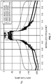
- Figures 5 through 7 are simulation results that graphically illustrate the band-limiting function of one exemplary implementation of the band-limited observation receiver 52 of Figure 4 . More specifically, Figure 5 is a frequency-domain graph of simulation results that illustrates the contribution of different non-linear terms to the power amplifier output signal. As illustrated, the amplitudes of the third-order and fifth-order terms are smaller than that of the first-order term by orders of magnitude. Also, the amplitudes of the third-order and fifth-order terms diminish as frequency moves away from the carrier frequency. From Figure 5 , the inventors have found that the non-linear terms are well represented in-band (i.e., in the desired frequency band of the power amplifier output signal).
- Figure 6 illustrates the band-limiting function of the band-limited observation receiver 52
- Figure 7 illustrates the contribution of different non-linear terms after application of the band-limiting function of Figure 6 (e.g., after passing through the narrowband filter 66).
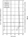
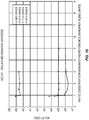
- Figures 8 and 9 illustrate simulation results for Adjacent Channel Leakage Ratio (ACLR1) and Normalized Mean Square Error (NMSE) versus a ratio of the observation bandwidth of the band-limited observation receiver 52 over the bandwidth of the reference signal for third, fifth, seventh, and ninth-order predistortion by the predistorter 48 according to one exemplary implementation of the system 42 of Figure 4 .
- ACLR1 Adjacent Channel Leakage Ratio
- NMSE Normalized Mean Square Error
- a single band 40 MHz Wideband Code Division Multiple Access (WCDMA) signal having a Peak-to-Average Power Ratio (PAPR) of 7.1 decibels (dB) was used along with a memoryless Saleh model for the power amplifier 46.
- the values shown in Figures 8 and 9 correspond to the average over 270 iterations.
- Figures 8 and 9 illustrate that a band-limiting ratio of 1.5 is appropriate for third-order and fifth-order predistortion.
- Figure 8 shows an inflection point at a band-limiting ratio of 2 for seventh-order and ninth-order predistortion. Therefore, it is preferable that a band-limiting ratio of 2 be used for seventh-order and ninth-order predistortion in order to avoid performance degradation.
- a band-limiting ratio of 2 is a significant improvement for seventh-order and ninth-order predistortion, which would normally require the observation receiver 26 to support seven to nine times the bandwidth of the reference signal.
- a concurrent multi-band signal is desired.
- a "concurrent multi-band signal” is a signal that contains frequency components occupying multiple frequency bands (i.e., a first continuous frequency band, a second continuous frequency band, etc.) with no frequency components between adjacent frequency bands.
- a concurrent multi-band signal having two frequency bands is referred to herein as a concurrent dual-band signal.
- Figure 10 illustrates a system 74 that includes a digital predistortion system 76 that compensates for non-linearities of a power amplifier 78 when amplifying a concurrent dual-band signal, where the digital predistortion system 76 includes a band-limited adaptation subsystem 80 according to one embodiment of the present disclosure.
- the two frequency bands of the concurrent dual-band signal are referred to herein as frequency bands A and B. Note, however, that the system 74 can easily be extended for concurrent multi-band signals having more than two frequency bands.
- the digital predistortion system 76 includes separate predistorters 82 and 84 for the two frequency bands of the concurrent dual-band signal and the band-limited adaptation subsystem 80.
- the band-limited adaptation subsystem 80 includes a band-limited observation receiver 86 that includes separate band-limiting functions for the two frequency bands of the concurrent dual-band signal and separate adaptors 88 and 90 for the two frequency bands of the concurrent dual-band signal arranged as shown.
- the band-limited observation receiver 86 includes a band-limiting function for frequency band A of the concurrent dual-band signal such that a bandwidth observed by the band-limited observation receiver 86 for frequency band A, and thus the bandwidth supported by the band-limited adaptation subsystem 80 for frequency band A, is less than N MAX_ORDER times a bandwidth of an input signal to the predistorters 82 and 84 for frequency band A, where N MAX_ORDER is a maximum order of non-linearity of the power amplifier 78 for which the digital predistortion system 76 is designed to compensate.
- the bandwidth of the input signal to the predistorters 82 and 84 for frequency band A is also a desired bandwidth of a power amplifier output signal output by the power amplifier 78 for frequency band A.
- the bandwidth observed by the band-limited observation receiver 86 for frequency band A is in a range of and including 1.5 to 2 times the bandwidth of the input signal to the predistorters 82 and 84 for frequency band A (i.e., the bandwidth of reference signal (S R-SAND_A )).
- the band-limited observation receiver 86 includes a band-limiting function for frequency band B of the concurrent dual-band signal such that a bandwidth observed by the band-limited observation receiver 86 for frequency band B, and thus a bandwidth supported by the band-limited adaptation subsystem 80 for frequency band B, is less than N MAX_ORDER times a bandwidth an input signal to the predistorters 82 and 84 for frequency band B.
- the bandwidth of the input signal to the predistorters 82 and 84 for frequency band B is also a desired bandwidth of the power amplifier output signal output by the power amplifier 78 for frequency band B.
- the bandwidth observed by the band-limited observation receiver 86 for frequency band B is in a range of and including 1.5 to 2 times the bandwidth of the input signal to the predistorters 82 and 84 for frequency band B (i.e., the bandwidth of reference signal (S R-BAND_B )).
- a baseband source 92 generates a baseband input signal for frequency band A of the concurrent dual-band signal
- a baseband source 94 generates a baseband input signal for frequency band B of the concurrent dual-band signal.
- the baseband input signals from the baseband sources 92 and 94 are up-sampled to desired sampling rates by up-sampling circuitry 96 and up-sampling circuitry 98, respectively.
- the desired sampling rate for the up-sampled baseband input signal for frequency band A would be greater than N MAX_ORDER xB A , where B A is a bandwidth of the baseband input signal for frequency band A and thus a bandwidth of the reference signal (S R-BAND_A ) and a desired bandwidth for frequency band A in the power amplifier output signal output by the power amplifier 78.
- the desired sampling rate for the up-sampled baseband input signal for frequency band B would be greater than N MAX_ORDER xB B , where B B is a bandwidth of the baseband input signal for frequency band B and thus a bandwidth of the reference signal (S R-BAND_B ) and a desired bandwidth for frequency band B in the power amplifier output signal output by the power amplifier 78.
- the predistorters 82 and 84 generate predistorted baseband input signals for frequency bands A and B, respectively.
- the predistortion introduced by the predistorters 82 and 84 compensates for up to the maximum order of non-linearity of the power amplifier 78 for which the digital predistortion system 76 is designed to compensate (N MAX_ORDER ).
- the maximum order of non-linearity of the power amplifier 78 for which the digital predistortion system 76 is designed to compensate is at least the third-order. In one preferred embodiment, the maximum order of non-linearity of the power amplifier 78 for which the digital predistortion system 76 is designed to compensate is the fifth-order.
- the predistorted baseband input signals are then upconverted and quadrature modulated by corresponding upconverters 100 and 102 and quadrature modulators 104 and 106, respectively.
- the resulting upconverted, modulated, and predistorted input signals are then combined by combiner circuitry 108 to provide a combined predistorted input signal, which is then converted from digital to analog by a DAC 110 to thereby provide a power amplifier input signal.
- the DAC 110 is between the combiner circuitry 108 and the power amplifier 78 in this embodiment, the location of the DAC 110 can vary depending on the particular implementation.
- the power amplifier 78 amplifies the power amplifier input signal to provide the power amplifier output signal.
- the power amplifier output signal is the concurrent dual-band signal having frequency bands A and B.
- the power amplifier output signal is fed back into the band-limited observation receiver 86.
- the band-limited adaptation subsystem 80 and in particular the band-limited observation receiver 86, introduces band-limiting functions for frequency bands A and B that significantly reduce an observation bandwidth of the band-limited observation receiver 86 for both frequency bands A and B and thus a sampling rate requirement of the adaptors 88 and 90.
- the bandwidth observed by the band-limited observation receiver 86 for frequency band A is denoted as B LIMITED_A .
- the bandwidth (B LIMITED_A ) observed by the band-limited observation receiver 86 for frequency band A is less than N MAX_ORDER xB A and, in one preferred embodiment, is in a range of and including 1.5 to 2 times B A .
- the sampling rate requirement for the adaptor 88 is reduced from greater than N MAX_ORDER xB A for the conventional digital predistortion system 10 ( Figure 1 ) to greater than B LIMITED_A .
- the sampling rate requirement for the adaptor 88 is reduced from 200 MHz to less than 200 MHz and, in one preferred embodiment, 60 MHz to 80 MHz.
- the bandwidth observed by the band-limited observation receiver 86 for frequency band B is denoted as B LIMITED_B .
- the bandwidth (B LIMITED_B ) observed by the band-limited observation receiver 86 for frequency band B is less than N MAX_ORDER xB B and, in one preferred embodiment, is in a range of and including 1.5 to 2 times B B .
- B LIMITED_B is less than N MAX_ORDER xB B
- the sampling rate requirement for the adaptor 90 is reduced from greater than N MAX_ORDER xB B for the conventional digital predistortion system 10 ( Figure 1 ) to greater than B LIMITED_B .
- the sampling rate requirement for the adaptor 90 is reduced from 200 MHz to less than 200 MHz and, in one preferred embodiment, 60 MHz to 80 MHz.
- the band-limited observation receiver 86 includes a separate observation path for each of the frequency bands A and B of the power amplifier output signal.
- the observation path for frequency band A includes a narrowband filter 112, an attenuator 114, downconversion and demodulation circuitry 116, and an ADC 118 arranged as shown.
- the output of the band-limited observation receiver 86 for frequency band A is referred to herein as a band-limited observation signal (S O-BL_A ) for frequency band A.
- the narrowband filter 112 serves as a band-limiting function of the band-limited observation receiver 86 for frequency band A.
- the narrowband filter 112 has a pass-band that includes frequency band A of the power amplifier output signal (e.g., centered at the carrier frequency for frequency band A), and a bandwidth of the pass-band of the narrowband filter 112 is less than N MAX_ORDER times the desired bandwidth of frequency band A of the power amplifier output signal (i.e., less than N MAX_ORDER xB A ).
- the bandwidth of the pass-band of the narrowband filter 112 is in a range of and including 1.5 to 2 times the desired bandwidth of frequency band A of the power amplifier output signal, where N MAX_ORDER is greater than or equal to 3 or more and preferably greater than or equal to 5.
- a bandwidth of the band-limited observation signal (S O-BL_A ) for frequency band A is significantly less than what it would otherwise be if using the conventional adaptation approach ( Figure 1 ). This, in turn, allows the adaptor 88 and the ADC 118 to run at significantly lower sampling rates.
- the observation path for frequency band B includes a narrowband filter 120, an attenuator 122, downconversion and demodulation circuitry 124, and an ADC 126 arranged as shown.
- the output of the band-limited observation receiver 86 for frequency band B is referred to herein as a band-limited observation signal (S O-BL_B ) for frequency band B.
- the narrowband filter 120 serves as a band-limiting function of the band-limited observation receiver 86 for frequency band B.
- the narrowband filter 120 has a pass-band that includes frequency band B of the power amplifier output signal (e.g., centered at the carrier frequency for frequency band B), and a bandwidth of the pass-band of the narrowband filter 120 is less than N MAX_ORDER times the desired bandwidth of frequency band B of the power amplifier output signal (i.e., less than N MAX_ORDER xB B ).
- the bandwidth of the pass-band of the narrowband filter 120 is in a range of and including 1.5 to 2 times the desired bandwidth of frequency band B of the power amplifier output signal, where N MAX_ORDER is greater than or equal to 3 or more and preferably greater than or equal to 5.
- a bandwidth of the band-limited observation signal (S O-BL_B ) for frequency band B is significantly less than what it would otherwise be if using the conventional adaptation approach ( Figure 1 ). This, in turn, allows the adaptor 90 and the ADC 126 to run at significantly lower sampling rates.
- the adaptor 88 adaptively configures the predistorter 82 based on a comparison of time-aligned as well as gain and phase adjusted versions of the band-limited observation signal (S O-BL_A ) and the reference signal (S R-BAND_A ), which in this case is the up-sampled baseband input signal input into the predistorters 82 and 84 for frequency band A.
- the adaptor 88 configures one or more parameters of the predistorter 82 (e.g., one or more coefficients of a polynomial predistortion function) based on the comparison of the time-aligned as well as gain and phase adjusted versions of the band-limited observation signal (S O-BL_A ) and the reference signal (S R-BAND_A ) for frequency band A using any suitable adaptation technique.
- one or more parameters of the predistorter 82 e.g., one or more coefficients of a polynomial predistortion function
- the adaptor 90 adaptively configures the predistorter 84 based on a comparison of time-aligned as well as gain and phase adjusted versions of the band-limited observation signal (S O-BL_B ) and the reference signal (S R-BAND_B ), which in this case is the up-sampled baseband input signal that is input into the predistorters 82 and 84 for frequency band B.
- the adaptor 90 configures one or more parameters of the predistorter 84 (e.g., one or more coefficients of a polynomial predistortion function) based on the comparison of the time-aligned as well as gain and phase adjusted versions of the band-limited observation signal (S O-BL_B ) and the reference signal (S R-BAND_B ) for frequency band B using any suitable adaptation technique.
- one or more parameters of the predistorter 84 e.g., one or more coefficients of a polynomial predistortion function
- the narrowband filters 112 and 120 serve as the band-limiting functions of the band-limited observation receiver 86 in the embodiment of Figure 10
- the present disclosure is not limited thereto.
- the band-limiting functions of the band-limited observation receiver 86 may alternatively be implemented at baseband (e.g., narrowband filters at baseband either before or after the ADCs 118 and 126).
- Figures 11 and 12 illustrate simulation results for ACLR1 and NMSE versus a ratio of the bandwidth of the band-limited observation signal over the bandwidth of the reference signal for fifth-order non-linearities of the power amplifier 78 when using different models for the power amplifier 78 according to one exemplary implementation of the system 74 of Figure 10 .
- a concurrent dual-band WCDMA signal with 2x40 MHz frequency bands separated by 500 MHz was used.
- the PAPR of the power amplifier input signal was 9.1 dB.
- the values illustrated in Figures 11 and 12 correspond to average values for the two frequency bands over 70 iterations.
- the four different models for the power amplifier 78 that were used for the simulations were: Hyperbolic tangent (tanh) without memory effects, Saleh model without memory effects, Hyperbolic tangent including memory effects, and Saleh model including memory effects.
- the simulation results in Figures 11 and 12 show similar behavior between ACLR1 and NMSE metrics. All curves are relatively flat until they hit a band-limiting ratio of 1.5. At that point, the hyperbolic tangent model curves go through an inflection point, and the performances start to degrade quickly. When the band-limiting ratio is 1, the Saleh curves also experience an inflection point. Based on these observations, in one preferred embodiment, the band-limiting ratio is selected as 1.5. In other words, the bandwidth supported by the band-limited observation receiver 86 is selected as 1.5 times the bandwidth of the reference signals. In this example, the bandwidths of the two reference signals are the same.
- Figures 13 and 14 illustrate simulation results for ACLR1 and NMSE versus a ratio of the bandwidth of the band-limited observation signal over the bandwidth of the reference signal for third, fifth, seventh, and ninth-order predistortion by the predistorters 82 and 84 according to one exemplary implementation of the system 74 of Figure 10 .
- a concurrent dual-band WCDMA signal with 2x40 MHz frequency bands separated by 500 MHz was used.
- the PAPR of the power amplifier input signal was 9.1 dB.
- the values illustrated in Figures 13 and 14 correspond to average values for the two frequency bands over 270 iterations.
- the memoryless Saleh model was used to model the power amplifier 78 because it is more challenging to linearize than the Hyperbolic tangent model.
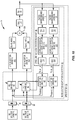
- Figure 15 illustrates a system 128 that includes a digital predistortion system 130 that compensates for non-linearities of a power amplifier 132 when amplifying a concurrent dual-band signal, where the digital predistortion system 130 includes a band-limited adaptation subsystem 134 according to another embodiment of the present disclosure.
- the two frequency bands of the concurrent dual-band signal are referred to herein as frequency bands A and B. Note, however, that the system 128 can easily be extended for concurrent multi-band signals having more than two frequency bands.
- the digital predistortion system 130 includes a combined predistorter 136 (hereinafter “predistorter 136") for the two frequency bands A and B of the concurrent dual-band signal and the band-limited adaptation subsystem 134.
- the band-limited adaptation subsystem 134 includes a band-limited observation receiver 138 that includes separate band-limiting functions for the two frequency bands of the concurrent dual-band signal and a combined adaptor 140 (hereinafter "adaptor 140") for the two frequency bands A and B of the concurrent dual-band signal arranged as shown.
- the band-limited observation receiver 138 includes a band-limiting function for frequency band A of the concurrent dual-band signal such that a bandwidth observed by the band-limited observation receiver 138 for frequency band A is less than N MAX_ORDER times a bandwidth of frequency band A in an input signal input into the predistorter 136, where N MAX_ORDER is a maximum order of non-linearity of the power amplifier 132 for which the digital predistortion system 130 is designed to compensate.
- the bandwidth observed by the band-limited observation receiver 138 for frequency band A is in a range of and including 1.5 to 2 times the bandwidth of frequency band A in the input signal input into the predistorter 136.
- the band-limited observation receiver 138 includes a band-limiting function for frequency band B of the concurrent dual-band signal such that a bandwidth observed by the band-limited observation receiver 138 for frequency band B is less than N MAX_ORDER times a bandwidth of frequency band B in the input signal input into the predistorter 136, where N MAX_ORDER is a maximum order of non-linearity of the power amplifier 132 for which the digital predistortion system 130 is designed to compensate.
- the bandwidth observed by the band-limited observation receiver 138 for frequency band B is in a range of and including 1.5 to 2 times the bandwidth of frequency band B in the input signal input into the predistorter 136.
- a baseband source 142 generates a baseband input signal for frequency band A of the concurrent dual-band signal
- a baseband source 144 generates a baseband input signal for frequency band B of the concurrent dual-band signal.
- the baseband input signals from the baseband sources 142 and 144 are up-sampled to a desired sampling rate by up-sampling circuitry 146 and up-sampling circuitry 148, respectively.
- the up-sampled baseband input signals are then tuned to different predefined intermediate frequencies (IF1 and IF2) by tuning circuitry 150 and tuning circuitry 152, respectively.
- IF1 -IF2.
- the tuned input signals are then combined by combiner circuitry 154 to provide a combined input signal.
- the combined input signal is predistorted by the predistorter 136.
- the predistortion introduced by the predistorter 136 compensates for up to the predefined maximum order of non-linearities of the power amplifier 132.
- the predistorted input signal is then tuned, filtered, and upconverted to a desired carrier frequency for frequency band A by tuning circuitry 156, a filter 158, and an upconverter 160.
- the predistorted signal is tuned, filtered, and up-converted to a desired carrier frequency for frequency band B by tuning circuitry 162, a filter 164, and an upconverter 166.
- the resulting upconverted signals are combined by combiner circuitry 168 to provide a combined radio frequency signal.
- the combined radio frequency signal is digital-to-analog converted by a DAC 170 to provide a power amplifier input signal, which is then amplified by the power amplifier 132 to provide the power amplifier output signal.
- the power amplifier output signal is a concurrent dual-band signal. Note that while the DAC 170 is located between the combiner circuitry 168 and the power amplifier 132 in this embodiment, the location of the DAC 170 can vary depending on the particular implementation.
- the power amplifier output signal is fed back into the band-limited observation receiver 138.
- the power amplifier output signal is filtered by a wideband filter 172 to remove undesired frequency components and then attenuated by an attenuator 174.
- the filtered and attenuated power amplifier output signal is then passed through separate observation paths for each of the frequency bands A and B of the power amplifier output signal. More specifically, for frequency band A, the filtered and attenuated power amplifier output signal is downconverted to baseband by a downconverter 176.
- the downconverted signal is then filtered by a narrowband filter 178 to thereby apply the band-limiting function for frequency band A.
- the narrowband filter 178 has a bandwidth that is less than N MAX_ORDER times the bandwidth of frequency band A in the input signal to the predistorter 136 (i.e., the combined reference signal input into the adaptor 140) and, in one preferred embodiment, has a bandwidth that is in a range of 1.5 to 2 times the bandwidth of frequency band A in the input signal to the predistorter 136.
- the filtered signal is then tuned to IF1 by tuning circuitry 180.
- the filtered and attenuated power amplifier output signal is downconverted to baseband by a downconverter 182.
- the downconverted signal is then filtered by a narrowband filter 184 to thereby apply the band-limiting function for frequency band B.
- the narrowband filter 184 has a bandwidth that is less than N MAX_ORDER times the bandwidth of frequency band B in the input signal to the predistorter 136 (i.e., the combined reference signal input into the adaptor 140) and, in one preferred embodiment, has a bandwidth that is in a range of 1.5 to 2 times the bandwidth of frequency band B in the input signal to the predistorter 136.
- the filtered signal is then tuned to IF2 by tuning circuitry 186.
- the tuned signals from the tuning circuitry 180 and 186 are combined by combiner circuitry 188 and the resulting signal is converted from analog to digital by an ADC 190 to thereby provide a band-limited combined observation signal (S O_COMB ).
- the adaptor 140 adaptively configures the predistorter 136 based on a comparison of time-aligned as well as gain and phase adjusted versions of the band-limited combined observation signal (S O_COMB ) and the reference signal (S R ), which in this case is the combined IF signal input into the predistorter 136.
- the adaptor 140 configures one or more parameters of the predistorter 136 (e.g., one or more coefficients of a polynomial predistortion function) based on the comparison of the time-aligned as well as gain and phase adjusted versions of the band-limited combined observation signal (S O_COMB ) and the reference signal (S R ) using any suitable adaptation technique.
- the predistorter 136 e.g., one or more coefficients of a polynomial predistortion function
- the desired sampling rate for the adaptor 140 is conventionally selected to be high enough to accommodate the frequency expansion resulting from the non-linearity of the power amplifier 132.
- the desired sampling rate would have been greater than N MAX_ORDER xB IF-COMBINED , where B IF-COMBINED is the bandwidth of the combined signal input into the adaptor 140.
- the band-limited adaptation subsystem 134 introduces band-limiting functions for frequency bands A and B that significantly reduce the sampling rate requirements of the adaptor 140 and the ADC 190.
- the desired sampling rate for the adaptor 140 is greater than B LIMITED_COMBINED , where B LIMITED_COMBINED is a combined bandwidth observed by the band-limited observation receiver 138.
- B LIMITED_COMBINED is a combined bandwidth observed by the band-limited observation receiver 138.
- the combined bandwidth observed by the band-limited observation receiver 138 is the bandwidth of the band-limited combined observation signal output by the band-limited observation receiver 138. Due to the band-limiting functions of the band-limited observation receiver 138 for frequency bands A and B, the combined bandwidth observed by the band-limited observation receiver 138 is less than N MAX_ORDER xB IF-COMBINED . As such, the sampling rate requirement for the adaptor 140 is reduced.
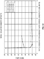
- Figures 16 and 17 illustrate simulation results for ACLR1 and NMSE versus a ratio of the bandwidth of the band-limited observation signal over the bandwidth of the reference signal for third, fifth, seventh, and ninth-order predistortion by the predistorter 136 according to one exemplary implementation of the system 128 of Figure 15 .
- a concurrent dual-band WCDMA signal with 2x40 MHz frequency bands separated by 500 MHz was used.
- the PAPR of the power amplifier input signal was 9.1 dB.
- the values illustrated in Figures 16 and 17 correspond to average values for the two frequency bands over 270 iterations.
- the memoryless Saleh model was used to model the power amplifier 132 because it is more challenging to linearize than the Hyperbolic tangent model.
- the curves in Figures 16 and 17 all have inflection points at a band-limiting ratio of 1.5 except for third-order predistortion.
- the band-limiting ratio is the ratio of the observed bandwidth for frequency band A in the combined observation signal over the bandwidth of frequency band A in the reference signal or, conversely, the ratio of the observed bandwidth for frequency band B in the combined observation signal over the bandwidth of frequency band B in the reference signal.
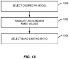
- Figure 18 is a flow chart that illustrates a process for selecting a band-limiting ratio for a band-limited digital predistortion subsystem according to one embodiment of the present disclosure.
- a desired model for a power amplifier to be linearized by the band-limited digital predistortion subsystem is selected (step 1000).
- the desired model is a model that most accurately reflects the operation of the power amplifier.
- ACLR and/or NMSE values for at least one order of non-linearity of the power amplifier for different band-limited ratios are determined using the desired model for the power amplifier (step 1002).
- ACLR and/or NMSE values are determined for the fifth-order and, in some embodiments, the third-order using the desired model for the power amplifier.
- a band-limited ratio that corresponds to an inflection point(s) in the ACLR and/or NMSE values is selected a desired band-limited ratio (step 1004).
- the inflection point for the ACLR values corresponds to the band-limited ratio above which the ACLR values remain the same, or at least substantially the same.
- the inflection point for the NMSE values corresponds to the band-limited ratio above with the NMSE values remain the same, or at least substantially the same.
Landscapes
- Engineering & Computer Science (AREA)
- Power Engineering (AREA)
- Physics & Mathematics (AREA)
- Nonlinear Science (AREA)
- Computer Networks & Wireless Communication (AREA)
- Signal Processing (AREA)
- Algebra (AREA)
- General Physics & Mathematics (AREA)
- Mathematical Analysis (AREA)
- Mathematical Optimization (AREA)
- Pure & Applied Mathematics (AREA)
- Amplifiers (AREA)
Claims (16)
- Système (42) comprenant :un amplificateur de puissance (46) configuré pour amplifier un signal d'entrée d'amplificateur de puissance afin de fournir un signal de sortie d'amplificateur de puissance ; etun système de prédistorsion numérique (44) configuré pour compenser un ordre de non linéarité allant jusqu'à un ordre maximal prédéfini de l'amplificateur de puissance (46), qui équivaut à NMAX_ORDER, dans lequel NMAX_ORDER est un entier positif et comprenant :- un sous-système d'adaptation à bande limitée (50) comprenant un récepteur d'observation à bande limitée (52), le récepteur d'observation à bande limitée (52) comprenant un filtre à bande étroite (66),- dans lequel une bande passante d'observation, BLIMITED, du sous-système d'adaptation à bande limitée (50) esti) supérieure ou égale à une bande passante, B, d'un signal de référence du sous-système d'adaptation à bande limitée (50) etii) inférieure à NMAX_ORDER fois B, et- dans lequel le filtre à bande étroite (66)i) est configuré pour servir de fonction de limitation de bande du récepteur d'observation à bande limitée (52),ii) a une bande passante qui inclut une bande de fréquence désirée du signal de sortie d'amplificateur de puissance, dans lequel le signal de sortie est un signal à bande unique ayant la bande passante désirée qui est égale à la bande passante du signal de référence etiii) a une bande passante étant inférieure à NMAX_ORDER fois B,dans lequel le système (42) est configuré pour sélectionner un rapport à bande limitée pour le sous-système d'adaptation à bande limitée (52), le rapport à bande limitée étant un rapport de la bande passante d'observation sur la bande passante du signal de référence, en :- définissant, pour chacun de NMAX_ORDER, une courbe respective et ayant le rapport à bande limitée sur l'abscisse et un d'un rapport de fuite de puissance dans le canal adjacent, ACLR, et l'erreur quadratique moyenne normalisée, NMSE, sur l'ordonnée, et- sélectionnant, de la NMAX_ORDER ème courbe d'intérêt respectif, le rapport à bande limitée au point d'inflexion de la NMAX_ORDER ème courbe d'intérêt,et dans lequel le système de prédistorsion numérique (44) comprend en outre :- un dispositif de prédistorsion (48) configuré pour appliquer une prédistorsion à un signal d'entrée pour fournir un signal d'entrée prédistordu et le système (42) comprend en outre un circuit configuré pour traiter le signal d'entrée prédistordu afin de fournir le signal d'entrée d'amplificateur de puissance à une fréquence porteuse désirée ; etdans lequel le sous-système d'adaptation à bande limitée (50) comprend en outre- un adaptateur (54) configuré pour commander de manière adaptative le dispositif de prédistorsion (48) afin de compenser jusqu'à NMAX_ORDER sur la base du signal de référence et BLIMITED.
- Système (42) selon la revendication 1, dans lequel :- le signal de référence est le signal d'entrée.
- Système (42) selon la revendication 1, dans lequel :
le filtre à bande étroite (66) est configuré pour filtrer le signal de sortie d'amplificateur de puissance pour fournir un signal de sortie d'amplificateur de puissance filtré. - Système (42) selon la revendication 3, dans lequel la largeur de bande de la bande passante du filtre à bande étroite (66) est dans une plage de et incluant 1.5 à 2 fois la bande passante désirée du signal de sortie d'amplificateur de puissance.
- Système (74) comprenant :un amplificateur de puissance (78) configuré pour amplifier un signal d'entrée d'amplificateur de puissance afin de fournir un signal de sortie d'amplificateur de puissance ; etun système de prédistorsion numérique (76) configuré pour compenser un ordre de non linéarité allant jusqu'à un ordre maximal prédéfini de l'amplificateur de puissance (78), qui équivaut à NMAX_ORDER, dans lequel NMAX_ORDER est un entier positif et comprenant :- un sous-système d'adaptation à bande limitée (80) comprenant un récepteur d'observation à bande limitée (86), le récepteur d'observation à bande limitée (86) comprenant un filtre à bande étroite (112,120),- dans lequel une bande passante d'observation, BLIMITED, du sous-système d'adaptation à bande limitée (50) esti) supérieure ou égale à une bande passante, B, d'un signal de référence du sous-système d'adaptation à bande limitée (80) etii) inférieure à NMAX_ORDER fois B, et- dans lequel le filtre à bande étroite (112,120)i) est configuré pour servir de fonction de limitation de bande du récepteur d'observation à bande limitée (86),ii) a une bande passante qui inclut une bande de fréquence désirée du signal de sortie d'amplificateur de puissance, etiii) a une bande passante étant inférieure à NMAX_ORDER fois B,dans lequel le système (74) est configuré pour sélectionner un rapport à bande limitée pour le sous-système d'adaptation à bande limitée (80), le rapport à bande limitée étant un rapport de la bande passante d'observation sur la bande passante du signal de référence, en :- définissant, pour chacun de NMAX_ORDER, une courbe respective et ayant le rapport à bande limitée sur l'abscisse et un d'un rapport de fuite de puissance dans le canal adjacent, ACLR, et l'erreur quadratique moyenne normalisée, NMSE, sur l'ordonnée, et- sélectionnant, de la NMAX_ORDER ème courbe d'intérêt respectif, le rapport à bande limitée au point d'inflexion de la NMAX_ORDER ème courbe d'intérêt,dans lequel le signal de sortie d'amplificateur de puissance est un signal multi-bandes simultané ayant une pluralité de bandes de fréquence et, pour chaque bande de fréquence de la pluralité de bandes de fréquence du signal de sortie d'amplificateur de puissance, le sous-système d'adaptation à bande limitée (80) est configuré pour prendre en charge une bande passante qui est inférieure à NMAX_ORDER fois une bande passante désirée de la bande de fréquence,dans lequel :le système de prédistorsion numérique (76) comprend en outre une pluralité de dispositifs de prédistorsion (82,84) comprenant un dispositif de prédistorsion séparés pour chacun d'une pluralité de signaux d'entrée, dans lequel chacun de la pluralité de signaux d'entrée est un signal d'entrée pour une bande de fréquence différente de la pluralité de bandes de fréquence du signal de sortie d'amplificateur de puissance ;le récepteur d'observation à bande limitée (86) est configuré pour recevoir et traiter le signal de sortie d'amplificateur de puissance pour fournir une pluralité de signaux d'observation à bande limitée, dans lequel chaque signal d'observation à bande limitée de la pluralité de signaux d'observation à bande limitée est un signal d'observation pour une bande correspondante de la pluralité de bandes de fréquence du signal de sortie d'amplificateur de puissance et a une bande passante qui est inférieure à NMAX_ORDER fois une bande passante désirée de la bande de fréquence correspondante de la pluralité de bandes de fréquence du signal de sortie d'amplificateur de puissance ; etdans lequel le sous-système d'adaptation à bande limitée (80) comprend en outre une pluralité d'adaptateurs (88,90) comprenant un adaptateur séparé pour chacun de la pluralité de dispositifs de prédistorsion (82,84), chaque adaptateur (88,90) de la pluralité d'adaptateurs (88,90) étant configuré pour commander de manière adaptative un dispositif de prédistorsion correspondant de la pluralité de dispositifs de prédistorsion (82,84) pour compenser jusqu'à NMAX_ORDER sur la base d'un signal de référence pour la bande de fréquence correspondante de la pluralité de bandes de fréquence du signal de sortie d'amplificateur de puissance et un signal correspondant de la pluralité de signaux d'observation à bande limitée.
- Système (74) selon la revendication 5, dans lequel :
pour chaque adaptateur (88,90) de la pluralité d'adaptateurs (88,90), le signal de référence pour la bandes de fréquence correspondante de la pluralité de bandes de fréquence est un signal correspondant de la pluralité de signaux d'entrée, et le système (74) comprend en outre des circuits configurés pour traiter la pluralité de signaux d'entrée prédistordus pour fournir le signal d'entrée d'amplificateur de puissance. - Système (74) selon la revendication 5, dans lequel le récepteur d'observation à bande limitée (86) comprend, pour chaque bande de fréquence de la pluralité de bandes de fréquence du signal de sortie d'amplificateur de puissance :le filtre à bande étroite (112,120) configuré pour filtrer le signal de sortie d'amplificateur de puissance pour fournir un signal de sortie d'amplificateur de puissance filtré ; etdes circuits configurés pour traiter le signal de sortie d'amplificateur de puissance filtré pour fournir le signal d'observation à bande limitée.
- Système (74) selon la revendication 7, dans lequel la largeur de bande de la bande passante du filtre à bande étroite (112,120) est dans une plage de et incluant 1.5 à 2 fois la bande passante désirée du signal de sortie d'amplificateur de puissance.
- Système (128) comprenant :un amplificateur de puissance (132) configuré pour amplifier un signal d'entrée d'amplificateur de puissance afin de fournir un signal de sortie d'amplificateur de puissance ; etun système de prédistorsion numérique (130) configuré pour compenser un ordre de non linéarité allant jusqu'à un ordre maximal prédéfini de l'amplificateur de puissance (132), qui équivaut à NMAX_ORDER, dans lequel NMAX_ORDER est un entier positif et comprenant :- un sous-système d'adaptation à bande limitée (134) comprenant un récepteur d'observation à bande limitée (138), le récepteur d'observation à bande limitée (138) comprenant un filtre à bande étroite (178,184),- dans lequel une bande passante d'observation, BLIMITED, du sous-système d'adaptation à bande limitée (134) esti) supérieure ou égale à une bande passante, B, d'un signal de référence du sous-système d'adaptation à bande limitée (134) etii) inférieure à NMAX_ORDER fois B, et- dans lequel le filtre à bande étroite (184)i) est configuré pour servir de fonction de limitation de bande du récepteur d'observation à bande limitée (138),ii) a une bande passante qui inclut une bande de fréquence désirée du signal de sortie d'amplificateur de puissance, etiii) a une bande passante étant inférieure à NMAX_ORDER fois B,dans lequel le système (128) est configuré pour sélectionner un rapport à bande limitée pour le sous-système d'adaptation à bande limitée (138), le rapport à bande limitée étant un rapport de la bande passante d'observation sur la bande passante du signal de référence, en :- définissant, pour chacun de NMAX_ORDER, une courbe respective et ayant le rapport à bande limitée sur l'abscisse et un d'un rapport de fuite de puissance dans le canal adjacent, ACLR, et l'erreur quadratique moyenne normalisée, NMSE, sur l'ordonnée, et- sélectionnant, de la NMAX_ORDER ème courbe d'intérêt respectif, le rapport à bande limitée au point d'inflexion de la NMAX_ORDER ème courbe d'intérêt,dans lequel le signal de sortie d'amplificateur de puissance est un signal multi-bandes simultané ayant une pluralité de bandes de fréquence et, pour chaque bande de fréquence de la pluralité de bandes de fréquence du signal de sortie d'amplificateur de puissance, le sous-système d'adaptation à bande limitée (134) est configuré pour prendre en charge une bande passante qui est inférieure à NMAX_ORDER fois une bande passante désirée de la bande de fréquence,dans lequel :
le système de prédistorsion numérique (130) comprend en outre :- un circuit d'accord (150,152) configuré pour accorder une pluralité de signaux d'entrée en une pluralité de fréquence intermédiaire différente afin de fournir ainsi une pluralité de signaux d'entrée accordés ;- un circuit de combinaison (154) configuré pour combiner la pluralité de signaux d'entrée accordés pour fournir un signal combiné ;- un dispositif de prédistorsion (136) configuré pour effectuer une prédistorsion du signal combiné pour fournir un signal prédistordu ; et- un circuit configuré pour traiter le signal prédistordu pour fournir le signal d'entrée d'amplificateur de puissance ; etdans lequel le récepteur d'observation à bande limitée (138) est configuré pour recevoir et traiter le signal de sortie d'amplificateur de puissance pour fournir un signal d'observation à bande limitée combinée ayant une pluralité de bandes de fréquence qui correspondent à la pluralité de bandes de fréquence du signal de sortie d'amplificateur de puissance, dans lequel pour chaque bande de fréquence de la pluralité de bandes de fréquence du signal d'observation à bande limitée combinée, la bande de fréquence a une largeur de bande qui est inférieure à NMAX_ORDER fois la bande passante désirée de la bande de fréquence du signal de sortie d'amplificateur de puissance ; etun adaptateur (140) configuré pour commander de manière adaptative le dispositif de prédistorsion (136) pour compenser jusqu'à l'ordre maximal prédéfini de non linéarité de l'amplificateur de puissance (132) sur la base du signal de référence et du signal d'observation à bande limitée combiné. - Système (128) selon la revendication 9, dans lequel- le signal de référence est le signal combiné ; et- le récepteur d'observation à bande limitée (138) comprend une fonction de limitation de bande séparée pour chacune de la pluralité de bandes de fréquence du signal de sortie d'amplificateur de puissance.
- Système (128) selon la revendication 9, dans lequel le récepteur d'observation à bande limitée (138) comprend, pour chaque bande de fréquence de la pluralité de bandes de fréquence du signal de sortie d'amplificateur de puissance :un circuit configuré pour traiter le signal de sortie d'amplificateur de puissance pour fournir un signal d'observation séparé pour la bande de fréquence, le circuit comprenant le filtre à bande étroite (178,184) ; etun circuit de combinaison (188) configuré pour combiner les signaux d'observation séparés pour la pluralité de bande de fréquences du signal de sortie d'amplificateur de puissance pour fournir le signal d'observation à bande limitée combinée.
- Système (128) selon la revendication 11, dans lequel la largeur de bande de la bande passante du filtre à bande étroite (178,184) est dans une plage de et incluant 1.5 à 2 fois la bande passante désirée du signal de sortie d'amplificateur de puissance.
- Système selon la revendication 4, 8 ou 12, dans lequel :- NMAX_ORDER est supérieur ou égal au troisième ordre ; ou- NMAX_ORDER est supérieur ou égal au cinquième ordre.
- Procédé pour un système (42) comprenant un sous-système d'adaptation à bande limitée (50), le sous-système d'adaptation à bande limitée (50) comprenant un récepteur d'observation à bande limitée (52) et le récepteur d'observation à bande limitée (52) comprenant un filtre à bande étroite (66), le procédé comprenant de :effectuer une prédistorsion, par un dispositif de prédistorsion (48), d'un signal d'entrée pour fournir un signal d'entrée prédistordu, dans lequel le signal d'entrée prédistordu est traité pour fournir le signal d'entrée d'amplificateur de puissance à une fréquence porteuse désirée ;amplifier, par un amplificateur de puissance (46), le signal d'entrée d'amplificateur de puissance pour fournir un signal de sortie d'amplificateur de puissance ; etcompenser, par un système de prédistorsion numérique, (44), jusqu'à un ordre maximal prédéfini de l'amplificateur de puissance (46), qui équivaut à NMAX_ORDER, dans lequel NMAX_ORDER est un entier positif, sur la base d'un signal de référence et une bande passante d'observation, BLIMITED,- dans lequel BLIMITED du sous-système d'adaptation à bande limitée (50) est i) supérieur ou égal à une bande passante, B, d'un signal de référence du sous-système d'adaptation à bande limitée (50) etii) inférieur à NMAX_ORDER fois B, et- dans lequel le filtre à bande étroite (66) i) sert comme une fonction de limitation de bande du récepteur d'observation à bande limitée (52), ii) a une bande passante qui inclut une bande de fréquence désirée du signal de sortie d'amplificateur de puissance et iii) a une bande passante étant inférieure à NMAX_ORDER fois B, dans lequel le signal de sortie est un signal à bande unique ayant la bande passante désirée qui est égale à la bande passante du signal de référence,dans lequel le procédé comprend en outre de :
sélectionner un rapport à bande limitée pour le sous-système d'adaptation à bande limitée (52), le rapport à bande limitée étant un rapport de la bande passante d'observation sur la bande passante du signal de référence, en :- définissant, pour chacun de NMAX_ORDER, une courbe respective et ayant le rapport à bande limitée sur l'abscisse et un d'un rapport de fuite de puissance dans le canal adjacent, ACLR, et l'erreur quadratique moyenne normalisée, NMSE, sur l'ordonnée, et- sélectionnant, de la NMAX_ORDER ème courbe d'intérêt respectif, le rapport à bande limitée au point d'inflexion de la NMAX_ORDER ème courbe d'intérêt. - Procédé pour un système (74) comprenant un sous-système d'adaptation à bande limitée (80), le sous-système d'adaptation à bande limitée (80) comprenant un récepteur d'observation à bande limitée (86) et le récepteur d'observation à bande limitée (86) comprenant un filtre à bande étroite (112,120), le procédé comprenant de :amplifier, par un amplificateur de puissance (78), un signal d'entrée d'amplificateur de puissance pour fournir un signal de sortie d'amplificateur de puissance ; etcompenser, par un système de prédistorsion numérique, un ordre de non linéarité allant jusqu'à un ordre maximal prédéfini de l'amplificateur de puissance (78), qui équivaut à NMAX_ORDER, dans lequel NMAX_ORDER est un entier positif,- dans lequel une bande passante d'observation, BLIMITED, du sous-système d'adaptation à bande limitée (80) est i) supérieure ou égale à une bande passante, B, d'un signal de référence du sous-système d'adaptation à bande limitée (80) et ii) inférieure à NMAX_ORDER fois B, et- dans lequel le filtre à bande étroite (112,180) i) sert comme une fonction de limitation de bande du récepteur d'observation à bande limitée (86), ii) a une bande passante qui inclut une bande de fréquence désirée du signal de sortie d'amplificateur de puissance et iii) a une bande passante étant inférieure à NMAX_ORDER fois B, dans lequel le procédé comprend en outre de :sélectionner un rapport à bande limitée pour le sous-système d'adaptation à bande limitée (86), le rapport à bande limitée étant un rapport de la bande passante d'observation sur la bande passante du signal de référence, en :- définissant, pour chacun de NMAX_ORDER, une courbe respective et ayant le rapport à bande limitée sur l'abscisse et un d'un rapport de fuite de puissance dans le canal adjacent, ACLR, et l'erreur quadratique moyenne normalisée, NMSE, sur l'ordonnée, et- sélectionnant, de la NMAX_ORDER ème courbe d'intérêt respectif, le rapport à bande limitée au point d'inflexion de la NMAX_ORDER ème courbe d'intérêt,dans lequel le signal de sortie d'amplificateur de puissance est un signal multi-bandes simultané ayant une pluralité de bandes de fréquence et, pour chaque bande de fréquence de la pluralité de bandes de fréquence du signal de sortie d'amplificateur de puissance, le sous-système d'adaptation à bande limitée (80) est configuré pour prendre en charge une bande passante qui est inférieure à NMAX_ORDER fois une bande passante désirée de la bandes de fréquence,dans lequel :le système de prédistorsion numérique (76) comprend en outre une pluralité de dispositifs de prédistorsion (82, 84) comprenant un dispositif de prédistorsion séparé pour chacun d'une pluralité de signaux d'entrée, dans lequel chacun de la pluralité de signaux d'entrée est un signal d'entrée pour une bande de fréquence différente de la pluralité de bandes de fréquence du signal de sortie d'amplificateur de puissance ;dans lequel le procédé comprend en outre de :recevoir et traiter, par le récepteur d'observation à bande limitée (86), le signal de sortie d'amplificateur de puissance pour fournir une pluralité de signaux d'observation à bande limitée, dans lequel chaque signal d'observation à bande limitée de la pluralité de signaux d'observation à bande limitée est un signal d'observation pour une bande correspondante de la pluralité de bandes de fréquence du signal de sortie d'amplificateur de puissance et a une bande passante qui est inférieure à NMAX_ORDER fois une bande passante désirée de la bande de fréquence correspondante de la pluralité de bande de fréquence du signal de sortie d'amplificateur de puissance ;dans lequel une pluralité d'adaptateurs (89,90) comprend un adaptateur séparé pour chacun de la pluralité de dispositifs de prédistorsion (82, 84), chaque adaptateur (88, 90) de la pluralité d'adaptateurs (88, 90)le procédé comprenant en outre de commander de manière adaptative un dispositif de prédistorsion correspondant de la pluralité de dispositifs de prédistorsion (82,84) pour compenser jusqu'à NMAX_ORDER sur la base d'un signal de référence pour la bandes de fréquence correspondantes de la pluralité de bandes de fréquence du signal de sortie d'amplificateur de puissance et un signal correspondant de la pluralité de signaux d'observation à bande limitée.
- Procédé pour un système (128) comprenant un sous-système d'adaptation à bande limitée (134), le sous-système d'adaptation à bande limitée (134) comprenant un récepteur d'observation à bande limitée (138) et le récepteur d'observation à bande limitée (138) comprenant un filtre à bande étroite (178,184), le procédé comprenant de :amplifier, par un amplificateur de puissance (132), un signal d'entrée d'amplificateur de puissance pour fournir un signal de sortie d'amplificateur de puissance ; etcompenser, par un système de prédistorsion numérique (130), un ordre de non linéarité allant jusqu'à un ordre maximal prédéfini de l'amplificateur de puissance (132), qui équivaut à NMAX_ORDER, dans lequel NMAX_ORDER est un entier positif,- dans lequel une bande passante d'observation, BLIMITED, du sous-système d'adaptation à bande limitée (134) est i) supérieure ou égale à une bande passante, B, d'un signal de référence du sous-système d'adaptation à bande limitée (134) etii) inférieure à NMAX_ORDER fois B, et- dans lequel le filtre à bande étroite (178, 184) i) sert comme une fonction de limitation de bande du récepteur d'observation à bande limitée (138), ii) a une bande passante qui inclut une bande de fréquence désirée du signal de sortie d'amplificateur de puissance et iii) a une bande passante étant inférieure à NMAX_ORDER fois B,dans lequel le procédé comprend en outre de :
sélectionner un rapport à bande limitée pour le sous-système d'adaptation à bande limitée (138), le rapport à bande limitée étant un rapport de la bande passante d'observation sur la bande passante du signal de référence, en :- définissant, pour chacun de NMAX_ORDER, une courbe respective et ayant le rapport à bande limitée sur l'abscisse et un d'un rapport de fuite de puissance dans le canal adjacent, ACLR, et l'erreur quadratique moyenne normalisée, NMSE, sur l'ordonnée, et- sélectionnant, de la NMAX_ORDER ème courbe d'intérêt respectif, le rapport à bande limitée au point d'inflexion de la NMAX_ORDER ème courbe d'intérêt,dans lequel le signal de sortie d'amplificateur de puissance est un signal multi-bandes simultané ayant une pluralité de bandes de fréquence et, pour chaque bande de fréquence de la pluralité de bandes de fréquence du signal de sortie d'amplificateur de puissance, le sous-système d'adaptation à bande limitée (134) est configuré pour prendre en charge une bande passante qui est inférieure à NMAX_ORDER fois une bande passante désirée de la bande de fréquence,dans lequel le procédé comprend en outre de :- accorder, par un circuit d'accord (150,152) du système de prédistorsion numérique (130), une pluralité de signaux d'entrée en une pluralité de fréquences intermédiaires différentes afin de fournir ainsi une pluralité de signaux d'entrée accordée ;- combiner, par un circuit de combinaison (154) du système de prédistorsion numérique (130), la pluralité de signaux d'entrée accordés pour fournir un signal combiné ;- effectuer une prédistorsion, par un dispositif de prédistorsion (136) du système de prédistorsion numérique (130), du signal combiné pour fournir un signal prédistordu ; et- traiter, par un circuit du système de prédistorsion numérique (130), le signal prédistordu pour fournir le signal d'entrée d'amplificateur de puissance ;- recevoir et traiter, par le récepteur d'observation à bande limitée (138), le signal de sortie d'amplificateur de puissance pour fournir un signal d'observation à bande limitée combinée ayant une pluralité de bandes de fréquence qui correspondent à la pluralité de bandes de fréquence du signal de sortie d'amplificateur de puissance, dans lequel pour chaque bande de fréquence de la pluralité de bandes de fréquence du signal d'observation à bande limitée combinée, la bande de fréquence a une largeur de bande qui est inférieure à NMAX_ORDER fois la bande passante désirée de la bande de fréquence du signal de sortie d'amplificateur de puissance ; et- commander de manière adaptative, par un adaptateur (140), le dispositif de prédistorsion (136) pour compenser jusqu'à l'ordre maximal prédéfini de non linéarité de l'amplificateur de puissance (132) sur la base du signal de référence et du signal d'observation à bande limitée combiné.
Applications Claiming Priority (2)
| Application Number | Priority Date | Filing Date | Title |
|---|---|---|---|
| US13/681,976 US8890609B2 (en) | 2012-11-20 | 2012-11-20 | Systems and methods for band-limited adaptation for PA linearization |
| PCT/IB2013/060282 WO2014080349A1 (fr) | 2012-11-20 | 2013-11-20 | Systèmes et procédés pour l'adaptation limitée en bande de linéarisation d'ap |
Publications (2)
| Publication Number | Publication Date |
|---|---|
| EP2923442A1 EP2923442A1 (fr) | 2015-09-30 |
| EP2923442B1 true EP2923442B1 (fr) | 2018-10-17 |
Family
ID=49725178
Family Applications (1)
| Application Number | Title | Priority Date | Filing Date |
|---|---|---|---|
| EP13802117.5A Not-in-force EP2923442B1 (fr) | 2012-11-20 | 2013-11-20 | Systèmes et procédés pour l'adaptation limitée en bande de linéarisation d'ap |
Country Status (4)
| Country | Link |
|---|---|
| US (1) | US8890609B2 (fr) |
| EP (1) | EP2923442B1 (fr) |
| CN (1) | CN104937841B (fr) |
| WO (1) | WO2014080349A1 (fr) |
Families Citing this family (25)
| Publication number | Priority date | Publication date | Assignee | Title |
|---|---|---|---|---|
| EP2759056A4 (fr) * | 2011-09-22 | 2015-06-03 | Dali Systems Co Ltd | Système et procédé d'accroissement de la bande passante pour la pré-distorsion numérique dans les systèmes de communication multicanaux en bande large |
| US8913689B2 (en) | 2012-09-24 | 2014-12-16 | Dali Systems Co. Ltd. | Wide bandwidth digital predistortion system with reduced sampling rate |
| JP2014116691A (ja) * | 2012-12-06 | 2014-06-26 | Samsung Electronics Co Ltd | 高周波増幅装置及び歪補償方法 |
| WO2014092617A1 (fr) * | 2012-12-13 | 2014-06-19 | Telefonaktiebolaget L M Ericsson (Publ) | Prédistorsion numérique pour des signaux de bande passante élevée |
| US9172334B2 (en) * | 2013-05-09 | 2015-10-27 | King Fahd University Of Petroleum And Minerals | Digital predistortion system and method with extended correction bandwidth |
| US20140362949A1 (en) * | 2013-06-11 | 2014-12-11 | Analog Devices Technology | Reduced bandwidth digital predistortion |
| US11265118B2 (en) * | 2013-06-26 | 2022-03-01 | Maxlinear Asia Singapore Private Limited | Spectrum analyzer integrated in a point-to-point outdoor unit |
| US9735741B2 (en) * | 2014-08-28 | 2017-08-15 | Analog Devices Global | Receivers for digital predistortion |
| US11057837B2 (en) * | 2016-03-15 | 2021-07-06 | Qualcomm Incorporated | Downlink power adjustment in narrowband wireless communications |
| US9848342B1 (en) * | 2016-07-20 | 2017-12-19 | Ccip, Llc | Excursion compensation in multipath communication systems having performance requirements parameters |
| EP3306817B8 (fr) * | 2016-10-07 | 2021-04-21 | Rohde & Schwarz GmbH & Co. KG | Procédé et système de prédistorsion |
| KR20190121825A (ko) | 2017-02-25 | 2019-10-28 | 나노세미, 인크. | 멀티밴드 디지털 전치왜곡기 |
| US10141961B1 (en) | 2017-05-18 | 2018-11-27 | Nanosemi, Inc. | Passive intermodulation cancellation |
| US10931318B2 (en) * | 2017-06-09 | 2021-02-23 | Nanosemi, Inc. | Subsampled linearization system |
| US11115067B2 (en) | 2017-06-09 | 2021-09-07 | Nanosemi, Inc. | Multi-band linearization system |
| US11323188B2 (en) | 2017-07-12 | 2022-05-03 | Nanosemi, Inc. | Monitoring systems and methods for radios implemented with digital predistortion |
| US11303251B2 (en) | 2017-10-02 | 2022-04-12 | Nanosemi, Inc. | Digital predistortion adjustment based on determination of load condition characteristics |
| US10644657B1 (en) | 2018-05-11 | 2020-05-05 | Nanosemi, Inc. | Multi-band digital compensator for a non-linear system |
| WO2019219185A1 (fr) * | 2018-05-16 | 2019-11-21 | Telefonaktiebolaget Lm Ericsson (Publ) | Atténuation d'interférences |
| US11863210B2 (en) | 2018-05-25 | 2024-01-02 | Nanosemi, Inc. | Linearization with level tracking |
| EP4109833A4 (fr) * | 2020-03-13 | 2023-07-26 | Huawei Technologies Co., Ltd. | Procédé et appareil de pré-compensation de signal |
| CN115413009A (zh) * | 2021-05-28 | 2022-11-29 | 华为技术有限公司 | 一种功率放大器非线性特征参数确定方法及相关装置 |
| US11736335B2 (en) * | 2021-12-06 | 2023-08-22 | Sumitomo Electric Device Innovations, Inc. | Dualband predistortion system for wireless communication |
| CN114884471A (zh) * | 2022-04-02 | 2022-08-09 | 西安烽火电子科技有限责任公司 | 一种整合时频域的预失真系统稳定性提高方法 |
| CN117811594A (zh) * | 2022-09-24 | 2024-04-02 | 华为技术有限公司 | 通信方法和装置 |
Family Cites Families (6)
| Publication number | Priority date | Publication date | Assignee | Title |
|---|---|---|---|---|
| US7577211B2 (en) * | 2004-03-01 | 2009-08-18 | Powerwave Technologies, Inc. | Digital predistortion system and method for linearizing an RF power amplifier with nonlinear gain characteristics and memory effects |
| KR101126401B1 (ko) * | 2004-05-11 | 2012-03-29 | 삼성전자주식회사 | 전력 증폭기에 디지털 전치 왜곡 장치 및 방법 |
| JP5995858B2 (ja) | 2010-11-18 | 2016-09-21 | テレフオンアクチーボラゲット エルエム エリクソン(パブル) | プログラマブルデジタルアップ/ダウンコンバージョンを用いる方法及び周波数アジャイル事前歪み送信器 |
| EP2759056A4 (fr) * | 2011-09-22 | 2015-06-03 | Dali Systems Co Ltd | Système et procédé d'accroissement de la bande passante pour la pré-distorsion numérique dans les systèmes de communication multicanaux en bande large |
| US8380144B1 (en) | 2011-09-30 | 2013-02-19 | Telefonaktiebolaget L M Ericsson (Publ) | Systems and methods for digital predistortion in a dual band transmitter |
| US8536943B2 (en) * | 2012-02-03 | 2013-09-17 | Telefonaktiebolaget Lm Ericsson (Publ) | Selective narrowband feedback for a digital predistorter |
-
2012
- 2012-11-20 US US13/681,976 patent/US8890609B2/en active Active
-
2013
- 2013-11-20 CN CN201380070957.7A patent/CN104937841B/zh not_active Expired - Fee Related
- 2013-11-20 WO PCT/IB2013/060282 patent/WO2014080349A1/fr not_active Ceased
- 2013-11-20 EP EP13802117.5A patent/EP2923442B1/fr not_active Not-in-force
Non-Patent Citations (1)
| Title |
|---|
| None * |
Also Published As
| Publication number | Publication date |
|---|---|
| CN104937841B (zh) | 2018-07-31 |
| CN104937841A (zh) | 2015-09-23 |
| US20140139286A1 (en) | 2014-05-22 |
| EP2923442A1 (fr) | 2015-09-30 |
| WO2014080349A1 (fr) | 2014-05-30 |
| US8890609B2 (en) | 2014-11-18 |
Similar Documents
| Publication | Publication Date | Title |
|---|---|---|
| EP2923442B1 (fr) | Systèmes et procédés pour l'adaptation limitée en bande de linéarisation d'ap | |
| US12176934B2 (en) | Predistortion circuit, method for generating a predistorted baseband signal, control circuit for a predistortion circuit, method to determine parameters for a predistortion circuit, and apparatus and method for predistorting a baseband signal | |
| US12407368B2 (en) | System and method for increasing bandwidth for digital predistortion in multi-channel wideband communication systems | |
| CA2821892C (fr) | Systemes et procedes pour une predistorsion numerique dans un emetteur a double bande | |
| US20200336161A1 (en) | Wide bandwidth digital predistortion system with reduced sampling rate | |
| EP2923444B1 (fr) | Prédistorsion numérique de complexité basse pour transmetteurs multibandes concurrentes | |
| EP2828971B1 (fr) | Procédés d'échantillonnage de bande passante pour récepteur d'observation destinés à être utilisés dans un système dpd pa pour des signaux à multiples bandes concurrentes | |
| EP2870693B1 (fr) | Procédé d'adaptation d'un débit d'échantillonnage faible permettant une linéarisation à double bande | |
| WO2013093861A1 (fr) | Prédistorsion adaptative utilisée pour un sous-système non linéaire basé sur un modèle en tant que concaténation d'un modèle non-linéaire suivi d'un modèle linéaire | |
| EP2795791A1 (fr) | Architecture d'émetteur à filtres rf non linéaires | |
| EP2795802B1 (fr) | Architecture d'un système de prédistorsion à bande passante étroite pour composants rf non linéaires | |
| HK1195829A (en) | System and method for increasing bandwidth for digital predistortion in multi-channel wideband communication systems | |
| HK1195829B (en) | System and method for increasing bandwidth for digital predistortion in multi-channel wideband communication systems |
Legal Events
| Date | Code | Title | Description |
|---|---|---|---|
| PUAI | Public reference made under article 153(3) epc to a published international application that has entered the european phase |
Free format text: ORIGINAL CODE: 0009012 |
|
| 17P | Request for examination filed |
Effective date: 20150511 |
|
| AK | Designated contracting states |
Kind code of ref document: A1 Designated state(s): AL AT BE BG CH CY CZ DE DK EE ES FI FR GB GR HR HU IE IS IT LI LT LU LV MC MK MT NL NO PL PT RO RS SE SI SK SM TR |
|
| AX | Request for extension of the european patent |
Extension state: BA ME |
|
| DAX | Request for extension of the european patent (deleted) | ||
| STAA | Information on the status of an ep patent application or granted ep patent |
Free format text: STATUS: EXAMINATION IS IN PROGRESS |
|
| 17Q | First examination report despatched |
Effective date: 20170518 |
|
| REG | Reference to a national code |
Ref country code: DE Ref legal event code: R079 Ref document number: 602013045298 Country of ref document: DE Free format text: PREVIOUS MAIN CLASS: H03F0003240000 Ipc: H03F0001320000 |
|
| GRAP | Despatch of communication of intention to grant a patent |
Free format text: ORIGINAL CODE: EPIDOSNIGR1 |
|
| STAA | Information on the status of an ep patent application or granted ep patent |
Free format text: STATUS: GRANT OF PATENT IS INTENDED |
|
| RIC1 | Information provided on ipc code assigned before grant |
Ipc: H04B 1/04 20060101ALN20180626BHEP Ipc: H04L 27/36 20060101ALI20180626BHEP Ipc: H03F 3/24 20060101ALI20180626BHEP Ipc: H03F 1/32 20060101AFI20180626BHEP Ipc: H03F 1/34 20060101ALI20180626BHEP |
|
| INTG | Intention to grant announced |
Effective date: 20180724 |
|
| GRAS | Grant fee paid |
Free format text: ORIGINAL CODE: EPIDOSNIGR3 |
|
| GRAA | (expected) grant |
Free format text: ORIGINAL CODE: 0009210 |
|
| STAA | Information on the status of an ep patent application or granted ep patent |
Free format text: STATUS: THE PATENT HAS BEEN GRANTED |
|
| AK | Designated contracting states |
Kind code of ref document: B1 Designated state(s): AL AT BE BG CH CY CZ DE DK EE ES FI FR GB GR HR HU IE IS IT LI LT LU LV MC MK MT NL NO PL PT RO RS SE SI SK SM TR |
|
| REG | Reference to a national code |
Ref country code: GB Ref legal event code: FG4D |
|
| REG | Reference to a national code |
Ref country code: CH Ref legal event code: EP |
|
| REG | Reference to a national code |
Ref country code: IE Ref legal event code: FG4D |
|
| REG | Reference to a national code |
Ref country code: DE Ref legal event code: R096 Ref document number: 602013045298 Country of ref document: DE Ref country code: AT Ref legal event code: REF Ref document number: 1055177 Country of ref document: AT Kind code of ref document: T Effective date: 20181115 |
|
| REG | Reference to a national code |
Ref country code: NL Ref legal event code: MP Effective date: 20181017 |
|
| REG | Reference to a national code |
Ref country code: LT Ref legal event code: MG4D |
|
| REG | Reference to a national code |
Ref country code: AT Ref legal event code: MK05 Ref document number: 1055177 Country of ref document: AT Kind code of ref document: T Effective date: 20181017 |
|
| PG25 | Lapsed in a contracting state [announced via postgrant information from national office to epo] |
Ref country code: NL Free format text: LAPSE BECAUSE OF FAILURE TO SUBMIT A TRANSLATION OF THE DESCRIPTION OR TO PAY THE FEE WITHIN THE PRESCRIBED TIME-LIMIT Effective date: 20181017 |
|
| PG25 | Lapsed in a contracting state [announced via postgrant information from national office to epo] |
Ref country code: LV Free format text: LAPSE BECAUSE OF FAILURE TO SUBMIT A TRANSLATION OF THE DESCRIPTION OR TO PAY THE FEE WITHIN THE PRESCRIBED TIME-LIMIT Effective date: 20181017 Ref country code: FI Free format text: LAPSE BECAUSE OF FAILURE TO SUBMIT A TRANSLATION OF THE DESCRIPTION OR TO PAY THE FEE WITHIN THE PRESCRIBED TIME-LIMIT Effective date: 20181017 Ref country code: LT Free format text: LAPSE BECAUSE OF FAILURE TO SUBMIT A TRANSLATION OF THE DESCRIPTION OR TO PAY THE FEE WITHIN THE PRESCRIBED TIME-LIMIT Effective date: 20181017 Ref country code: PL Free format text: LAPSE BECAUSE OF FAILURE TO SUBMIT A TRANSLATION OF THE DESCRIPTION OR TO PAY THE FEE WITHIN THE PRESCRIBED TIME-LIMIT Effective date: 20181017 Ref country code: NO Free format text: LAPSE BECAUSE OF FAILURE TO SUBMIT A TRANSLATION OF THE DESCRIPTION OR TO PAY THE FEE WITHIN THE PRESCRIBED TIME-LIMIT Effective date: 20190117 Ref country code: HR Free format text: LAPSE BECAUSE OF FAILURE TO SUBMIT A TRANSLATION OF THE DESCRIPTION OR TO PAY THE FEE WITHIN THE PRESCRIBED TIME-LIMIT Effective date: 20181017 Ref country code: AT Free format text: LAPSE BECAUSE OF FAILURE TO SUBMIT A TRANSLATION OF THE DESCRIPTION OR TO PAY THE FEE WITHIN THE PRESCRIBED TIME-LIMIT Effective date: 20181017 Ref country code: IS Free format text: LAPSE BECAUSE OF FAILURE TO SUBMIT A TRANSLATION OF THE DESCRIPTION OR TO PAY THE FEE WITHIN THE PRESCRIBED TIME-LIMIT Effective date: 20190217 Ref country code: BG Free format text: LAPSE BECAUSE OF FAILURE TO SUBMIT A TRANSLATION OF THE DESCRIPTION OR TO PAY THE FEE WITHIN THE PRESCRIBED TIME-LIMIT Effective date: 20190117 Ref country code: ES Free format text: LAPSE BECAUSE OF FAILURE TO SUBMIT A TRANSLATION OF THE DESCRIPTION OR TO PAY THE FEE WITHIN THE PRESCRIBED TIME-LIMIT Effective date: 20181017 |
|
| PG25 | Lapsed in a contracting state [announced via postgrant information from national office to epo] |
Ref country code: SE Free format text: LAPSE BECAUSE OF FAILURE TO SUBMIT A TRANSLATION OF THE DESCRIPTION OR TO PAY THE FEE WITHIN THE PRESCRIBED TIME-LIMIT Effective date: 20181017 Ref country code: PT Free format text: LAPSE BECAUSE OF FAILURE TO SUBMIT A TRANSLATION OF THE DESCRIPTION OR TO PAY THE FEE WITHIN THE PRESCRIBED TIME-LIMIT Effective date: 20190217 Ref country code: GR Free format text: LAPSE BECAUSE OF FAILURE TO SUBMIT A TRANSLATION OF THE DESCRIPTION OR TO PAY THE FEE WITHIN THE PRESCRIBED TIME-LIMIT Effective date: 20190118 Ref country code: RS Free format text: LAPSE BECAUSE OF FAILURE TO SUBMIT A TRANSLATION OF THE DESCRIPTION OR TO PAY THE FEE WITHIN THE PRESCRIBED TIME-LIMIT Effective date: 20181017 Ref country code: AL Free format text: LAPSE BECAUSE OF FAILURE TO SUBMIT A TRANSLATION OF THE DESCRIPTION OR TO PAY THE FEE WITHIN THE PRESCRIBED TIME-LIMIT Effective date: 20181017 |
|
| REG | Reference to a national code |
Ref country code: CH Ref legal event code: PL |
|
| REG | Reference to a national code |
Ref country code: DE Ref legal event code: R097 Ref document number: 602013045298 Country of ref document: DE |
|
| PG25 | Lapsed in a contracting state [announced via postgrant information from national office to epo] |
Ref country code: CZ Free format text: LAPSE BECAUSE OF FAILURE TO SUBMIT A TRANSLATION OF THE DESCRIPTION OR TO PAY THE FEE WITHIN THE PRESCRIBED TIME-LIMIT Effective date: 20181017 Ref country code: LU Free format text: LAPSE BECAUSE OF NON-PAYMENT OF DUE FEES Effective date: 20181120 Ref country code: IT Free format text: LAPSE BECAUSE OF FAILURE TO SUBMIT A TRANSLATION OF THE DESCRIPTION OR TO PAY THE FEE WITHIN THE PRESCRIBED TIME-LIMIT Effective date: 20181017 Ref country code: DK Free format text: LAPSE BECAUSE OF FAILURE TO SUBMIT A TRANSLATION OF THE DESCRIPTION OR TO PAY THE FEE WITHIN THE PRESCRIBED TIME-LIMIT Effective date: 20181017 |
|
| REG | Reference to a national code |
Ref country code: BE Ref legal event code: MM Effective date: 20181130 |
|
| REG | Reference to a national code |
Ref country code: IE Ref legal event code: MM4A |
|
| PLBE | No opposition filed within time limit |
Free format text: ORIGINAL CODE: 0009261 |
|
| STAA | Information on the status of an ep patent application or granted ep patent |
Free format text: STATUS: NO OPPOSITION FILED WITHIN TIME LIMIT |
|
| PG25 | Lapsed in a contracting state [announced via postgrant information from national office to epo] |
Ref country code: EE Free format text: LAPSE BECAUSE OF FAILURE TO SUBMIT A TRANSLATION OF THE DESCRIPTION OR TO PAY THE FEE WITHIN THE PRESCRIBED TIME-LIMIT Effective date: 20181017 Ref country code: SM Free format text: LAPSE BECAUSE OF FAILURE TO SUBMIT A TRANSLATION OF THE DESCRIPTION OR TO PAY THE FEE WITHIN THE PRESCRIBED TIME-LIMIT Effective date: 20181017 Ref country code: SK Free format text: LAPSE BECAUSE OF FAILURE TO SUBMIT A TRANSLATION OF THE DESCRIPTION OR TO PAY THE FEE WITHIN THE PRESCRIBED TIME-LIMIT Effective date: 20181017 Ref country code: CH Free format text: LAPSE BECAUSE OF NON-PAYMENT OF DUE FEES Effective date: 20181130 Ref country code: LI Free format text: LAPSE BECAUSE OF NON-PAYMENT OF DUE FEES Effective date: 20181130 Ref country code: MC Free format text: LAPSE BECAUSE OF FAILURE TO SUBMIT A TRANSLATION OF THE DESCRIPTION OR TO PAY THE FEE WITHIN THE PRESCRIBED TIME-LIMIT Effective date: 20181017 Ref country code: RO Free format text: LAPSE BECAUSE OF FAILURE TO SUBMIT A TRANSLATION OF THE DESCRIPTION OR TO PAY THE FEE WITHIN THE PRESCRIBED TIME-LIMIT Effective date: 20181017 |
|
| 26N | No opposition filed |
Effective date: 20190718 |
|
| PG25 | Lapsed in a contracting state [announced via postgrant information from national office to epo] |
Ref country code: IE Free format text: LAPSE BECAUSE OF NON-PAYMENT OF DUE FEES Effective date: 20181120 Ref country code: SI Free format text: LAPSE BECAUSE OF FAILURE TO SUBMIT A TRANSLATION OF THE DESCRIPTION OR TO PAY THE FEE WITHIN THE PRESCRIBED TIME-LIMIT Effective date: 20181017 |
|
| PG25 | Lapsed in a contracting state [announced via postgrant information from national office to epo] |
Ref country code: BE Free format text: LAPSE BECAUSE OF NON-PAYMENT OF DUE FEES Effective date: 20181130 |
|
| PG25 | Lapsed in a contracting state [announced via postgrant information from national office to epo] |
Ref country code: MT Free format text: LAPSE BECAUSE OF NON-PAYMENT OF DUE FEES Effective date: 20181120 |
|
| PG25 | Lapsed in a contracting state [announced via postgrant information from national office to epo] |
Ref country code: TR Free format text: LAPSE BECAUSE OF FAILURE TO SUBMIT A TRANSLATION OF THE DESCRIPTION OR TO PAY THE FEE WITHIN THE PRESCRIBED TIME-LIMIT Effective date: 20181017 |
|
| PG25 | Lapsed in a contracting state [announced via postgrant information from national office to epo] |
Ref country code: HU Free format text: LAPSE BECAUSE OF FAILURE TO SUBMIT A TRANSLATION OF THE DESCRIPTION OR TO PAY THE FEE WITHIN THE PRESCRIBED TIME-LIMIT; INVALID AB INITIO Effective date: 20131120 Ref country code: MK Free format text: LAPSE BECAUSE OF NON-PAYMENT OF DUE FEES Effective date: 20181017 Ref country code: CY Free format text: LAPSE BECAUSE OF FAILURE TO SUBMIT A TRANSLATION OF THE DESCRIPTION OR TO PAY THE FEE WITHIN THE PRESCRIBED TIME-LIMIT Effective date: 20181017 |
|
| PGFP | Annual fee paid to national office [announced via postgrant information from national office to epo] |
Ref country code: GB Payment date: 20221128 Year of fee payment: 10 Ref country code: FR Payment date: 20221123 Year of fee payment: 10 Ref country code: DE Payment date: 20221125 Year of fee payment: 10 |
|
| REG | Reference to a national code |
Ref country code: DE Ref legal event code: R119 Ref document number: 602013045298 Country of ref document: DE |
|
| GBPC | Gb: european patent ceased through non-payment of renewal fee |
Effective date: 20231120 |
|
| PG25 | Lapsed in a contracting state [announced via postgrant information from national office to epo] |
Ref country code: DE Free format text: LAPSE BECAUSE OF NON-PAYMENT OF DUE FEES Effective date: 20240601 |
|
| PG25 | Lapsed in a contracting state [announced via postgrant information from national office to epo] |
Ref country code: GB Free format text: LAPSE BECAUSE OF NON-PAYMENT OF DUE FEES Effective date: 20231120 |
|
| PG25 | Lapsed in a contracting state [announced via postgrant information from national office to epo] |
Ref country code: FR Free format text: LAPSE BECAUSE OF NON-PAYMENT OF DUE FEES Effective date: 20231130 |
|
| PG25 | Lapsed in a contracting state [announced via postgrant information from national office to epo] |
Ref country code: GB Free format text: LAPSE BECAUSE OF NON-PAYMENT OF DUE FEES Effective date: 20231120 Ref country code: FR Free format text: LAPSE BECAUSE OF NON-PAYMENT OF DUE FEES Effective date: 20231130 Ref country code: DE Free format text: LAPSE BECAUSE OF NON-PAYMENT OF DUE FEES Effective date: 20240601 |