EP2923507B1 - Procédé d'optimisation d'une connexion de réseau sans fil - Google Patents
Procédé d'optimisation d'une connexion de réseau sans fil Download PDFInfo
- Publication number
- EP2923507B1 EP2923507B1 EP13795460.8A EP13795460A EP2923507B1 EP 2923507 B1 EP2923507 B1 EP 2923507B1 EP 13795460 A EP13795460 A EP 13795460A EP 2923507 B1 EP2923507 B1 EP 2923507B1
- Authority
- EP
- European Patent Office
- Prior art keywords
- network
- network device
- devices
- antenna
- station
- Prior art date
- Legal status (The legal status is an assumption and is not a legal conclusion. Google has not performed a legal analysis and makes no representation as to the accuracy of the status listed.)
- Active
Links
- 238000000034 method Methods 0.000 title claims description 31
- 238000012360 testing method Methods 0.000 claims description 3
- 230000007423 decrease Effects 0.000 claims description 2
- 238000004891 communication Methods 0.000 description 6
- 230000007246 mechanism Effects 0.000 description 6
- OVGWMUWIRHGGJP-WVDJAODQSA-N (z)-7-[(1s,3r,4r,5s)-3-[(e,3r)-3-hydroxyoct-1-enyl]-6-thiabicyclo[3.1.1]heptan-4-yl]hept-5-enoic acid Chemical compound OC(=O)CCC\C=C/C[C@@H]1[C@@H](/C=C/[C@H](O)CCCCC)C[C@@H]2S[C@H]1C2 OVGWMUWIRHGGJP-WVDJAODQSA-N 0.000 description 4
- 230000008901 benefit Effects 0.000 description 4
- 230000000694 effects Effects 0.000 description 4
- 241000283014 Dama Species 0.000 description 3
- JNSGIVNNHKGGRU-JYRVWZFOSA-N diethoxyphosphinothioyl (2z)-2-(2-amino-1,3-thiazol-4-yl)-2-methoxyiminoacetate Chemical compound CCOP(=S)(OCC)OC(=O)C(=N/OC)\C1=CSC(N)=N1 JNSGIVNNHKGGRU-JYRVWZFOSA-N 0.000 description 3
- 101100161473 Arabidopsis thaliana ABCB25 gene Proteins 0.000 description 2
- 101000752249 Homo sapiens Rho guanine nucleotide exchange factor 3 Proteins 0.000 description 2
- 101100096893 Mus musculus Sult2a1 gene Proteins 0.000 description 2
- 102100021689 Rho guanine nucleotide exchange factor 3 Human genes 0.000 description 2
- 101150081243 STA1 gene Proteins 0.000 description 2
- 230000005540 biological transmission Effects 0.000 description 2
- 239000000872 buffer Substances 0.000 description 2
- 230000001419 dependent effect Effects 0.000 description 2
- 101000988961 Escherichia coli Heat-stable enterotoxin A2 Proteins 0.000 description 1
- 108700026140 MAC combination Proteins 0.000 description 1
- 230000015556 catabolic process Effects 0.000 description 1
- 230000003247 decreasing effect Effects 0.000 description 1
- 238000006731 degradation reaction Methods 0.000 description 1
- 238000013461 design Methods 0.000 description 1
- 238000001514 detection method Methods 0.000 description 1
- 238000002592 echocardiography Methods 0.000 description 1
- 238000005516 engineering process Methods 0.000 description 1
- 230000002708 enhancing effect Effects 0.000 description 1
- VJYFKVYYMZPMAB-UHFFFAOYSA-N ethoprophos Chemical compound CCCSP(=O)(OCC)SCCC VJYFKVYYMZPMAB-UHFFFAOYSA-N 0.000 description 1
- 230000001771 impaired effect Effects 0.000 description 1
- 230000002452 interceptive effect Effects 0.000 description 1
- 230000001788 irregular Effects 0.000 description 1
- 230000004048 modification Effects 0.000 description 1
- 238000012986 modification Methods 0.000 description 1
- 230000002085 persistent effect Effects 0.000 description 1
- 230000035755 proliferation Effects 0.000 description 1
- 230000004044 response Effects 0.000 description 1
- 230000003068 static effect Effects 0.000 description 1
Images

Classifications
-
- H—ELECTRICITY
- H04—ELECTRIC COMMUNICATION TECHNIQUE
- H04W—WIRELESS COMMUNICATION NETWORKS
- H04W76/00—Connection management
- H04W76/10—Connection setup
- H04W76/14—Direct-mode setup
-
- H—ELECTRICITY
- H04—ELECTRIC COMMUNICATION TECHNIQUE
- H04W—WIRELESS COMMUNICATION NETWORKS
- H04W24/00—Supervisory, monitoring or testing arrangements
- H04W24/02—Arrangements for optimising operational condition
-
- H—ELECTRICITY
- H04—ELECTRIC COMMUNICATION TECHNIQUE
- H04W—WIRELESS COMMUNICATION NETWORKS
- H04W24/00—Supervisory, monitoring or testing arrangements
- H04W24/08—Testing, supervising or monitoring using real traffic
-
- H—ELECTRICITY
- H04—ELECTRIC COMMUNICATION TECHNIQUE
- H04W—WIRELESS COMMUNICATION NETWORKS
- H04W74/00—Wireless channel access
- H04W74/08—Non-scheduled access, e.g. ALOHA
- H04W74/0808—Non-scheduled access, e.g. ALOHA using carrier sensing, e.g. carrier sense multiple access [CSMA]
- H04W74/0816—Non-scheduled access, e.g. ALOHA using carrier sensing, e.g. carrier sense multiple access [CSMA] with collision avoidance
Definitions
- the present invention relates to a method for optimizing a wireless network connection between a first device and a second device, in particular when at least one of the devices comprises a configurable antenna.
- Wireless Local Area Networks or WLANs e.g. according to the so-called Wi-Fi technology
- Wi-Fi Wireless Local Area Networks
- network protocols exist, for instance Wi-Fi's Medium Access protocol Carrier Sense Multiple Access - Collision Avoidance - CSMA-CA, which make sure that the medium is shared properly between the different devices.
- the underlying concept is, that each network device that has a packet to send has to wait until the medium is clear, and in case it is not, to respect a certain random back-off time before it can send its packet. In that way, collisions between packets can be avoided.
- hidden node also denoted as hidden station
- a third device exists, which is "visible" to the first device, but not visible to the second device.
- the third device is a hidden node for the second device.
- RTS/CTS Radio Transport Stream
- CTS Clear-To-Send packet
- RTS-CTS Clear-To-Send packet
- Each Wi-Fi node that hears either the CTS or the RTS packet has to respect the time requested to keep the medium free.
- the RTS-CTS method is not protecting broadcast frames. It is known that in densely populated areas people are losing their wireless connections repeatedly because the beacons from their wireless gateway or access point are too frequently colliding with packets from hidden Wi-Fi Nodes. This is described in more detail below.
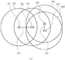
- Fig. 1 shows, in a symbolic plan view, a first, prior art wireless network configuration.
- the first network configuration comprises, as network devices, a first Access Point AP1 101, a second Access Point AP2 105, a first Station STA1 103, and a second station STA2 107.
- Fig. 1 also illustrates the visibility ranges of the network devices, i.e. the ranges inside of which the network devices are able to receive data from other network devices. They are the first Access Point's visibility range 102, the second Access Point's visibility range 106, the first Station's visibility range 104, and the second Station's visibility range 108.
- the first Access Point 101 is assumed to be wirelessly connected 109 to the first Station 103 forming a first local network
- the second Access Point 105 is assumed to be wirelessly connected 110 to the second Station 107 forming a second local network.
- the first Access Point 101 may correspond to a private network gateway located in the middle of an apartment.
- the first Station 103 may correspond to a laptop, operated within reach of and connected to the first Access Point 101, and located in a room near an outer wall of the apartment and near a street outside of the apartment.
- the second Access point 105 and the second Station 107 may correspond to parts of a very busy company network located across the street from the apartment.
- Beacons are broadcast management frames that can be said to constitute the "heartbeat" of a Wi-Fi network.
- An Access Point has to send out a beacon regularly. The time between beacons is configurable, but a value of 100ms is commonly used in Wi-Fi. If a Station is not seeing beacons anymore from the Access Point it is connected to, it considers that it has gone out of range and disconnects.
- the effects of hidden nodes are not only to deteriorate the WLAN performance during active usage, but also to cause persistent connect-disconnect cycles whenever other neighboring networks are in use. If the interfering network is a business WLAN, this basically means that connect-disconnect problems are to be expected all the time during working hours.
- Patent Publication US 7,103,386 B2 to Hoffmann et al. purports to disclose a method for operating an access point in a wireless local area network or WLAN.
- the access point includes a directional antenna for communicating with a plurality of remote stations, and the directional antenna includes a plurality of antenna patterns.
- the method includes creating an antenna database by associating between the access point and each remote station a respective measured signal quality corresponding to the plurality of antenna patterns. The respective measured signal qualities are determined by the access point based upon communications with each remote station.
- the method further includes determining for each remote station a preferred antenna pattern based upon the antenna database, and selecting a remote station and the corresponding preferred antenna pattern to communicate with.
- EDAMA Unlike DAMA, which uses a single MAC buffer for all antenna beams as in IEEE 802.11, EDAMA employs separate buffers for each of the antenna sectors and introduces an integrated network and MAC cross-layer design.
- the disclosed protocol can be seen to have the drawback that hidden nodes are not avoided.
- EP1699175 discloses a method to avoid occurrence of hidden terminals. Access Point sends a request message to terminals. The terminals send a response packet to the AP including information on the terminals they can hear/receive. The AP divides the terminals in groups of terminals that can hear each other, avoiding hidden terminals within each group.
- a communication path between a first network device and a second network device must first be established. Then, the communication path is used to compare network devices as seen by the first network device to network devices as seen by the second network device.
- Hidden Nodes are identified. Presence and use of a configurable antenna is assumed on the second network device. The configurable antenna is then modified in such a way that, as much as possible, the second network device is not seeing any network devices anymore that are hidden, i.e. invisible, to the first network device.
- the invention proposes a method to configure a wireless network connection between a first network device and a second network device having a configurable antenna.
- a data connection is established between the first network device and the second network device.
- the first Devices Seen List comprises identifications of all those third network devices from which the first network device, using the wireless network, is able to receive data.
- the second network device it is then tested, whether the second network device, using the wireless network and the configurable antenna, is able to receive data from any Extra Network Devices.
- Extra Network Devices we denote here any third network devices other than those comprised in the first Devices Seen List. If Extra Network Devices exist, the configurable antenna is modified in such a way as to minimize the number of Extra Network Devices. This amounts to a deliberate, direction dependent or non-omnidirectional restriction of the visibility range of the second network device.
- the advantage of the method according to the invention is that, by deliberately restricting the visibility range of the second network device, hidden nodes in general and the described beacon problems are avoided.
- the degree to which this can be achieved depends on the number of involved network devices, but also on the amount of flexibility of configuration that is provided by the specific configurable antenna.
- the known method for operating an access point including a directional antenna described above is based on signal quality. Assuming that the configurable antenna is a sectorized antenna, this amounts to deactivating all those sectors of the sectorized antenna, that do not actively contribute to the signal quality of the existing network connection. This can be seen to have the effect that in many cases, only a single sector of the antenna, namely that in which the other device is situated, will be kept active.
- the method to configure a wireless network connection proposed here amounts to deactivating only those parts of the directional characteristic of a sectorized antenna, that specifically would contribute hidden nodes. Sectors of the antenna directional characteristic that do not reduce the number of visible hidden nodes are maintained in operation. In that way, advantageously, a later entrance of other network devices into the wireless network is not hindered.
- Fig. 2 shows a second wireless network configuration for illustrating this invention.
- the second wireless network configuration comprises, denoted by respectively identical Reference Numerals, most network devices that are also contained in the first wireless network configuration.
- the first Station STA1 different from the situation shown in Fig. 1 , is assumed here to comprise a configurable antenna, and is therefore denoted by Reference Numeral 209.
- the configurable antenna of the first Station 209 is assumed here to comprise 8 angular sectors which can individually be used or disused, so that individual directional characteristics of the configurable antenna result.
- the 8 angular sectors are symbolically indicated in Fig. 2 in that the first Station's visibility range 104 is subdivided into sectors 201, 202, 203, 204, 205, 206, 207, and 208.
- the second wireless network configuration comprises also a third Station STA3 210.
- the first Access Point 101 is the embodiment of the first network device
- the first Station 209 is the embodiment of the second network device having the configurable antenna.
- a communication path or data connection is first established between the first network device 101 and the second network device 209.
- This data connection can be established over the wireless network, but alternatively it could be established by other means, wireless or wire-bound, proprietary or standardized. It is used only for the single step of sending the list of network devices seen by the first network device to the second network device.
- the first Access Point 101 sees the first Station 209 and the third Station 210.
- the first Devices Seen List consists of unique identifiers for these two network devices, and is sent to the first Station 209.
- the first Station 209 in its role as second network device, can start the step of testing whether it "sees” any Extra Network Devices. Since we are at the start of the method, the configurable antenna is preferably operated in omnidirectional mode. Therefore, in the example situation depicted in Fig. 2 , the first Station 209 in total sees the first Access Point 101, the third Station 210, the second access point 105, and the second Station 107. Of these, the first Access Point 101, by virtue of being one of the participants of the first local network, is not a third network device, and the third Station 210 is comprised in the first Devices Seen List. Therefore, only the second access point 105 and the second Station 107 remain as two Extra Network Devices.
- each of the antenna sectors is now sequentially investigated and set to passive only if the number of Extra Network Devices decreases.
- the resulting directional characteristic comprises the sectors 201-203 and 206-208, which together cover a 270 degree angle.
- the 90 degree angle of sectors 204, 205 is not covered, so that the Extra Network Devices situated in these two sectors are no longer visible.
- the antenna configuration at the beginning of the method is an omnidirectional one.
- the method can also be employed with an arbitrary start antenna configuration, which makes it possible to apply it repeatedly, in regular or irregular intervals.
- This has the advantage that it allows to take into account, on a running basis, slow variations in the wireless configuration.
- a step of modifying the configurable antenna would advantageously also comprise to set to active any antenna sectors as long as this does not increase the number of Extra Network Devices.
- the configuration method according to the present invention has been described in an embodiment which involves a static sectorized antenna. But the method can also be employed when the configurable antenna employs digital beam forming.
- the invention proposes a method for optimizing a wireless network connection when at least one of the devices comprises a configurable antenna. For avoiding Hidden Nodes problems, it is proposed to modify the configurable antenna in such a way that the number of third network devices seen only by the network device having the configurable antenna is minimized.
Landscapes
- Engineering & Computer Science (AREA)
- Computer Networks & Wireless Communication (AREA)
- Signal Processing (AREA)
- Mobile Radio Communication Systems (AREA)
- Radio Transmission System (AREA)
Claims (10)
- Procédé effectué par un deuxième dispositif réseau (209), ayant une antenne configurable, pour configurer une connexion réseau sans fil entre le deuxième dispositif réseau (209) et un premier dispositif réseau (101), comprenant les étapes suivantes :- établissement d'une connexion de données entre le deuxième dispositif réseau (209) et le premier dispositif réseau (101) ;- réception depuis le premier dispositif réseau (101) via la connexion de données d'une première liste de dispositifs vus comprenant les identifications de tous les troisièmes dispositifs réseau (210) à partir desquels le premier dispositif réseau (101), à l'aide d'un réseau sans fil, peut recevoir des données ;- test, par le deuxième dispositif réseau (209), de la capacité du deuxième dispositif réseau (209), à l'aide du réseau sans fil et de l'antenne configurable, à recevoir des données de dispositifs réseau supplémentaires étant des troisièmes dispositifs réseau (105, 107) autres que ceux compris dans la première liste de dispositifs vus ;- si le deuxième dispositif réseau (209) peut recevoir des données de dispositifs réseau supplémentaires, modification de l'antenne configurable de sorte que le nombre de dispositifs réseau supplémentaires soit réduit.
- Procédé selon la revendication 1, où l'étape de test comprend :- la compilation d'une deuxième liste de dispositifs vus comprenant des identifications de tous les troisièmes dispositifs réseau (105, 107, 210) à partir desquels le deuxième dispositif réseau (209) peut recevoir des données lorsqu'il utilise l'antenne configurable ;- la comparaison de la première liste de dispositifs vus avec la deuxième liste de dispositifs vus et la prise en compte de la capacité du deuxième dispositif réseau (209) à recevoir des données de dispositifs réseau supplémentaires si la deuxième liste de dispositifs vus comprend des identifications de troisièmes dispositifs réseau qui ne sont pas compris dans la première liste de dispositifs réseau.
- Procédé selon la revendication 1, utilisé dans un deuxième dispositif réseau (209) dont l'antenne configurable a des secteurs d'antenne distincts (201, 202, 203, 204, 205, 206, 207, 208) qui peuvent être individuellement actifs ou passifs, dans lequel l'étape de modification comprend, pour chacun des secteurs d'antenne, sa configuration en mode passif si cela réduit le nombre de dispositifs réseau supplémentaires.
- Procédé selon la revendication 3, dans lequel au début du procédé, tous les secteurs d'antenne sont configurés en mode actif.
- Procédé selon la revendication 3, dans lequel l'étape de modification comprend, pour chacun des secteurs d'antenne, sa configuration en mode actif si cela n'augmente pas le nombre de dispositifs réseau supplémentaires.
- Procédé selon l'une quelconque des revendications 1 à 5, où la connexion de données est établie à l'aide de la connexion réseau sans fil.
- Procédé selon la revendication 6, où pour la connexion de données, l'antenne configurable est utilisée en mode omnidirectionnel.
- Procédé selon l'une quelconque des revendications 1 à 5, où la connexion de données est établie par un moyen différent de la connexion réseau sans fil.
- Dispositif réseau (209) ayant une antenne configurable, et étant équipé et configuré pour effectuer un procédé selon la revendication 1.
- Système pour configurer une connexion réseau sans fil, comprenant un premier dispositif réseau (101) et un deuxième dispositif réseau (209) ayant une antenne configurable, le premier dispositif réseau (101) étant équipé et configuré pour établir une connexion de données avec le deuxième dispositif réseau (209), et pour envoyer au deuxième dispositif réseau (209) via la connexion de données une première liste de dispositifs vus comprenant des identifications de tous les troisièmes dispositifs réseau (210) à partir desquels le premier dispositif réseau (101), à l'aide d'un réseau sans fil, peut recevoir des données ; et le deuxième dispositif réseau (209) étant équipé et configuré pour effectuer un procédé selon la revendication 1.
Priority Applications (1)
| Application Number | Priority Date | Filing Date | Title |
|---|---|---|---|
| EP13795460.8A EP2923507B1 (fr) | 2012-11-21 | 2013-11-20 | Procédé d'optimisation d'une connexion de réseau sans fil |
Applications Claiming Priority (3)
| Application Number | Priority Date | Filing Date | Title |
|---|---|---|---|
| EP12306446.1A EP2736285A1 (fr) | 2012-11-21 | 2012-11-21 | Procédé d'optimisation d'une connexion de réseau sans fil |
| PCT/EP2013/074299 WO2014079894A1 (fr) | 2012-11-21 | 2013-11-20 | Procédé pour optimiser une connexion dans un réseau sans fil |
| EP13795460.8A EP2923507B1 (fr) | 2012-11-21 | 2013-11-20 | Procédé d'optimisation d'une connexion de réseau sans fil |
Publications (2)
| Publication Number | Publication Date |
|---|---|
| EP2923507A1 EP2923507A1 (fr) | 2015-09-30 |
| EP2923507B1 true EP2923507B1 (fr) | 2017-10-11 |
Family
ID=47469803
Family Applications (2)
| Application Number | Title | Priority Date | Filing Date |
|---|---|---|---|
| EP12306446.1A Withdrawn EP2736285A1 (fr) | 2012-11-21 | 2012-11-21 | Procédé d'optimisation d'une connexion de réseau sans fil |
| EP13795460.8A Active EP2923507B1 (fr) | 2012-11-21 | 2013-11-20 | Procédé d'optimisation d'une connexion de réseau sans fil |
Family Applications Before (1)
| Application Number | Title | Priority Date | Filing Date |
|---|---|---|---|
| EP12306446.1A Withdrawn EP2736285A1 (fr) | 2012-11-21 | 2012-11-21 | Procédé d'optimisation d'une connexion de réseau sans fil |
Country Status (6)
| Country | Link |
|---|---|
| US (1) | US9781754B2 (fr) |
| EP (2) | EP2736285A1 (fr) |
| JP (1) | JP6285948B2 (fr) |
| KR (1) | KR102052233B1 (fr) |
| CN (1) | CN104798394B (fr) |
| WO (1) | WO2014079894A1 (fr) |
Families Citing this family (3)
| Publication number | Priority date | Publication date | Assignee | Title |
|---|---|---|---|---|
| EP2996425A1 (fr) * | 2014-09-10 | 2016-03-16 | Thomson Licensing | Procédé pour faire fonctionner un premier noeud sans fil communiquant avec un second noeud sans fil, et dispositif de réalisation de ce procédé |
| WO2016053894A1 (fr) | 2014-09-30 | 2016-04-07 | Ruckus Wireless, Inc. | Mesure corrective basée sur une puissance reçue entre paquets |
| JP6162278B1 (ja) * | 2016-02-26 | 2017-07-12 | 日本電信電話株式会社 | 無線環境判定方法および無線通信システム |
Family Cites Families (9)
| Publication number | Priority date | Publication date | Assignee | Title |
|---|---|---|---|---|
| US7130289B2 (en) | 2002-03-14 | 2006-10-31 | Airmagnet, Inc. | Detecting a hidden node in a wireless local area network |
| US7200149B1 (en) * | 2002-04-12 | 2007-04-03 | Meshnetworks, Inc. | System and method for identifying potential hidden node problems in multi-hop wireless ad-hoc networks for the purpose of avoiding such potentially problem nodes in route selection |
| US7047046B2 (en) * | 2003-06-19 | 2006-05-16 | Ipr Licensing, Inc. | Antenna steering for an access point based upon probe signals |
| US7103386B2 (en) | 2003-06-19 | 2006-09-05 | Ipr Licensing, Inc. | Antenna steering and hidden node recognition for an access point |
| JP4711830B2 (ja) * | 2003-12-26 | 2011-06-29 | パナソニック株式会社 | 無線アクセスシステム |
| KR100713378B1 (ko) | 2006-01-13 | 2007-05-04 | 삼성전자주식회사 | 무선 통신 네트워크에서 숨은 스테이션 검출 방법 |
| JP4167691B2 (ja) * | 2006-03-06 | 2008-10-15 | 京セラ株式会社 | アダプティブアレイ基地局 |
| WO2009123112A1 (fr) * | 2008-03-31 | 2009-10-08 | 国立大学法人九州大学 | Système de réseau, nœud, procédé de retransmission par paquets, programme et support d’enregistrement |
| CN102752775B (zh) * | 2011-04-18 | 2015-04-22 | 中国移动通信集团公司 | 一种智能天线参数配置的发送和接收方法及装置 |
-
2012
- 2012-11-21 EP EP12306446.1A patent/EP2736285A1/fr not_active Withdrawn
-
2013
- 2013-11-20 JP JP2015543415A patent/JP6285948B2/ja not_active Expired - Fee Related
- 2013-11-20 EP EP13795460.8A patent/EP2923507B1/fr active Active
- 2013-11-20 KR KR1020157012981A patent/KR102052233B1/ko not_active Expired - Fee Related
- 2013-11-20 US US14/646,382 patent/US9781754B2/en not_active Expired - Fee Related
- 2013-11-20 WO PCT/EP2013/074299 patent/WO2014079894A1/fr not_active Ceased
- 2013-11-20 CN CN201380060870.1A patent/CN104798394B/zh active Active
Non-Patent Citations (1)
| Title |
|---|
| None * |
Also Published As
| Publication number | Publication date |
|---|---|
| KR20150086474A (ko) | 2015-07-28 |
| US20150312955A1 (en) | 2015-10-29 |
| JP2015535666A (ja) | 2015-12-14 |
| CN104798394B (zh) | 2019-02-15 |
| KR102052233B1 (ko) | 2019-12-04 |
| WO2014079894A1 (fr) | 2014-05-30 |
| JP6285948B2 (ja) | 2018-02-28 |
| CN104798394A (zh) | 2015-07-22 |
| US9781754B2 (en) | 2017-10-03 |
| EP2736285A1 (fr) | 2014-05-28 |
| EP2923507A1 (fr) | 2015-09-30 |
Similar Documents
| Publication | Publication Date | Title |
|---|---|---|
| CN105792279B (zh) | 更宽带宽操作中的冲突检测的方法和设备 | |
| US8913550B2 (en) | Clustering management in mmWave wireless systems | |
| EP3716495B1 (fr) | Opération de faisceau sectorisé pour des réseaux sans fil | |
| EP3966948B1 (fr) | Partage d'opportunité de transmission avec formation de faisceau | |
| WO2003026221A1 (fr) | Systeme et procede d'introduction de l'emission-reception par secteurs dans des reseaux sans fil | |
| KR102475656B1 (ko) | 밀리미터파 wlan 네트워크들에서의 할당 및 방향성 정보 분배 | |
| US20160081120A1 (en) | Communications method and device for single-frequency wireless local area network | |
| EP3915310B1 (fr) | Sélection de canal inter-réseau coopératif | |
| US7596388B2 (en) | Sectorized wireless communication network operating under 802.11 specifications | |
| CN121002990A (zh) | 用于超高可靠性的协调介质接入的技术 | |
| JP4588465B2 (ja) | 伝送制御方法 | |
| Han et al. | A multiple access method for integrated sensing and communication enabled UAV ad hoc network | |
| US9781754B2 (en) | Method for optimizing a wireless network connection | |
| WO2024037326A1 (fr) | Procédé et appareil de communication basés sur une contention de canal | |
| JP6315597B2 (ja) | 無線通信方法、無線通信システムおよび無線通信装置 | |
| CN116390121B (zh) | 一种信道侦听的方法以及相关装置 | |
| KR102377876B1 (ko) | 무선 랜에서의 기회적 간섭 정렬 방법 | |
| Aust et al. | Sector-based RTS/CTS access scheme for high density WLAN sensor networks | |
| Ulukan et al. | Angular MAC protocol with location based scheduling for wireless ad hoc networks | |
| KR20140077595A (ko) | 무선랜에서의 채널 정보의 이용 방법 | |
| CN113115469B (zh) | 信道接入方法及相关产品 | |
| JP2017028438A (ja) | 無線通信方法および無線通信システム | |
| Kaushik et al. | Evaluating the Performance of a MAC Protocol in WANET's using Directional Antennas: A Survey | |
| Lyakhov et al. | Direct transmission protection in IEEE 802.11 networks |
Legal Events
| Date | Code | Title | Description |
|---|---|---|---|
| PUAI | Public reference made under article 153(3) epc to a published international application that has entered the european phase |
Free format text: ORIGINAL CODE: 0009012 |
|
| 17P | Request for examination filed |
Effective date: 20150511 |
|
| AK | Designated contracting states |
Kind code of ref document: A1 Designated state(s): AL AT BE BG CH CY CZ DE DK EE ES FI FR GB GR HR HU IE IS IT LI LT LU LV MC MK MT NL NO PL PT RO RS SE SI SK SM TR |
|
| AX | Request for extension of the european patent |
Extension state: BA ME |
|
| DAX | Request for extension of the european patent (deleted) | ||
| 17Q | First examination report despatched |
Effective date: 20160610 |
|
| GRAP | Despatch of communication of intention to grant a patent |
Free format text: ORIGINAL CODE: EPIDOSNIGR1 |
|
| RIC1 | Information provided on ipc code assigned before grant |
Ipc: H04W 74/08 20090101ALN20170202BHEP Ipc: H04W 24/02 20090101AFI20170202BHEP |
|
| INTG | Intention to grant announced |
Effective date: 20170215 |
|
| GRAJ | Information related to disapproval of communication of intention to grant by the applicant or resumption of examination proceedings by the epo deleted |
Free format text: ORIGINAL CODE: EPIDOSDIGR1 |
|
| GRAP | Despatch of communication of intention to grant a patent |
Free format text: ORIGINAL CODE: EPIDOSNIGR1 |
|
| INTC | Intention to grant announced (deleted) | ||
| RIC1 | Information provided on ipc code assigned before grant |
Ipc: H04W 24/02 20090101AFI20170616BHEP Ipc: H04W 74/08 20090101ALN20170616BHEP |
|
| INTG | Intention to grant announced |
Effective date: 20170705 |
|
| GRAS | Grant fee paid |
Free format text: ORIGINAL CODE: EPIDOSNIGR3 |
|
| GRAA | (expected) grant |
Free format text: ORIGINAL CODE: 0009210 |
|
| AK | Designated contracting states |
Kind code of ref document: B1 Designated state(s): AL AT BE BG CH CY CZ DE DK EE ES FI FR GB GR HR HU IE IS IT LI LT LU LV MC MK MT NL NO PL PT RO RS SE SI SK SM TR |
|
| REG | Reference to a national code |
Ref country code: GB Ref legal event code: FG4D |
|
| REG | Reference to a national code |
Ref country code: CH Ref legal event code: EP |
|
| REG | Reference to a national code |
Ref country code: IE Ref legal event code: FG4D |
|
| REG | Reference to a national code |
Ref country code: AT Ref legal event code: REF Ref document number: 937034 Country of ref document: AT Kind code of ref document: T Effective date: 20171115 |
|
| REG | Reference to a national code |
Ref country code: FR Ref legal event code: PLFP Year of fee payment: 5 |
|
| REG | Reference to a national code |
Ref country code: DE Ref legal event code: R096 Ref document number: 602013027869 Country of ref document: DE |
|
| REG | Reference to a national code |
Ref country code: NL Ref legal event code: FP |
|
| REG | Reference to a national code |
Ref country code: LT Ref legal event code: MG4D |
|
| REG | Reference to a national code |
Ref country code: AT Ref legal event code: MK05 Ref document number: 937034 Country of ref document: AT Kind code of ref document: T Effective date: 20171011 |
|
| PG25 | Lapsed in a contracting state [announced via postgrant information from national office to epo] |
Ref country code: ES Free format text: LAPSE BECAUSE OF FAILURE TO SUBMIT A TRANSLATION OF THE DESCRIPTION OR TO PAY THE FEE WITHIN THE PRESCRIBED TIME-LIMIT Effective date: 20171011 Ref country code: LT Free format text: LAPSE BECAUSE OF FAILURE TO SUBMIT A TRANSLATION OF THE DESCRIPTION OR TO PAY THE FEE WITHIN THE PRESCRIBED TIME-LIMIT Effective date: 20171011 Ref country code: FI Free format text: LAPSE BECAUSE OF FAILURE TO SUBMIT A TRANSLATION OF THE DESCRIPTION OR TO PAY THE FEE WITHIN THE PRESCRIBED TIME-LIMIT Effective date: 20171011 Ref country code: SE Free format text: LAPSE BECAUSE OF FAILURE TO SUBMIT A TRANSLATION OF THE DESCRIPTION OR TO PAY THE FEE WITHIN THE PRESCRIBED TIME-LIMIT Effective date: 20171011 Ref country code: NO Free format text: LAPSE BECAUSE OF FAILURE TO SUBMIT A TRANSLATION OF THE DESCRIPTION OR TO PAY THE FEE WITHIN THE PRESCRIBED TIME-LIMIT Effective date: 20180111 |
|
| PG25 | Lapsed in a contracting state [announced via postgrant information from national office to epo] |
Ref country code: AT Free format text: LAPSE BECAUSE OF FAILURE TO SUBMIT A TRANSLATION OF THE DESCRIPTION OR TO PAY THE FEE WITHIN THE PRESCRIBED TIME-LIMIT Effective date: 20171011 Ref country code: RS Free format text: LAPSE BECAUSE OF FAILURE TO SUBMIT A TRANSLATION OF THE DESCRIPTION OR TO PAY THE FEE WITHIN THE PRESCRIBED TIME-LIMIT Effective date: 20171011 Ref country code: HR Free format text: LAPSE BECAUSE OF FAILURE TO SUBMIT A TRANSLATION OF THE DESCRIPTION OR TO PAY THE FEE WITHIN THE PRESCRIBED TIME-LIMIT Effective date: 20171011 Ref country code: BG Free format text: LAPSE BECAUSE OF FAILURE TO SUBMIT A TRANSLATION OF THE DESCRIPTION OR TO PAY THE FEE WITHIN THE PRESCRIBED TIME-LIMIT Effective date: 20180111 Ref country code: LV Free format text: LAPSE BECAUSE OF FAILURE TO SUBMIT A TRANSLATION OF THE DESCRIPTION OR TO PAY THE FEE WITHIN THE PRESCRIBED TIME-LIMIT Effective date: 20171011 Ref country code: GR Free format text: LAPSE BECAUSE OF FAILURE TO SUBMIT A TRANSLATION OF THE DESCRIPTION OR TO PAY THE FEE WITHIN THE PRESCRIBED TIME-LIMIT Effective date: 20180112 Ref country code: IS Free format text: LAPSE BECAUSE OF FAILURE TO SUBMIT A TRANSLATION OF THE DESCRIPTION OR TO PAY THE FEE WITHIN THE PRESCRIBED TIME-LIMIT Effective date: 20180211 |
|
| REG | Reference to a national code |
Ref country code: DE Ref legal event code: R097 Ref document number: 602013027869 Country of ref document: DE |
|
| PG25 | Lapsed in a contracting state [announced via postgrant information from national office to epo] |
Ref country code: DK Free format text: LAPSE BECAUSE OF FAILURE TO SUBMIT A TRANSLATION OF THE DESCRIPTION OR TO PAY THE FEE WITHIN THE PRESCRIBED TIME-LIMIT Effective date: 20171011 Ref country code: MC Free format text: LAPSE BECAUSE OF FAILURE TO SUBMIT A TRANSLATION OF THE DESCRIPTION OR TO PAY THE FEE WITHIN THE PRESCRIBED TIME-LIMIT Effective date: 20171011 Ref country code: EE Free format text: LAPSE BECAUSE OF FAILURE TO SUBMIT A TRANSLATION OF THE DESCRIPTION OR TO PAY THE FEE WITHIN THE PRESCRIBED TIME-LIMIT Effective date: 20171011 Ref country code: SK Free format text: LAPSE BECAUSE OF FAILURE TO SUBMIT A TRANSLATION OF THE DESCRIPTION OR TO PAY THE FEE WITHIN THE PRESCRIBED TIME-LIMIT Effective date: 20171011 Ref country code: CH Free format text: LAPSE BECAUSE OF NON-PAYMENT OF DUE FEES Effective date: 20171130 Ref country code: LI Free format text: LAPSE BECAUSE OF NON-PAYMENT OF DUE FEES Effective date: 20171130 Ref country code: CZ Free format text: LAPSE BECAUSE OF FAILURE TO SUBMIT A TRANSLATION OF THE DESCRIPTION OR TO PAY THE FEE WITHIN THE PRESCRIBED TIME-LIMIT Effective date: 20171011 |
|
| PLBE | No opposition filed within time limit |
Free format text: ORIGINAL CODE: 0009261 |
|
| STAA | Information on the status of an ep patent application or granted ep patent |
Free format text: STATUS: NO OPPOSITION FILED WITHIN TIME LIMIT |
|
| PG25 | Lapsed in a contracting state [announced via postgrant information from national office to epo] |
Ref country code: LU Free format text: LAPSE BECAUSE OF NON-PAYMENT OF DUE FEES Effective date: 20171120 Ref country code: IT Free format text: LAPSE BECAUSE OF FAILURE TO SUBMIT A TRANSLATION OF THE DESCRIPTION OR TO PAY THE FEE WITHIN THE PRESCRIBED TIME-LIMIT Effective date: 20171011 Ref country code: SM Free format text: LAPSE BECAUSE OF FAILURE TO SUBMIT A TRANSLATION OF THE DESCRIPTION OR TO PAY THE FEE WITHIN THE PRESCRIBED TIME-LIMIT Effective date: 20171011 Ref country code: PL Free format text: LAPSE BECAUSE OF FAILURE TO SUBMIT A TRANSLATION OF THE DESCRIPTION OR TO PAY THE FEE WITHIN THE PRESCRIBED TIME-LIMIT Effective date: 20171011 Ref country code: RO Free format text: LAPSE BECAUSE OF FAILURE TO SUBMIT A TRANSLATION OF THE DESCRIPTION OR TO PAY THE FEE WITHIN THE PRESCRIBED TIME-LIMIT Effective date: 20171011 |
|
| REG | Reference to a national code |
Ref country code: BE Ref legal event code: MM Effective date: 20171130 |
|
| REG | Reference to a national code |
Ref country code: IE Ref legal event code: MM4A |
|
| 26N | No opposition filed |
Effective date: 20180712 |
|
| PG25 | Lapsed in a contracting state [announced via postgrant information from national office to epo] |
Ref country code: MT Free format text: LAPSE BECAUSE OF NON-PAYMENT OF DUE FEES Effective date: 20171120 |
|
| PG25 | Lapsed in a contracting state [announced via postgrant information from national office to epo] |
Ref country code: IE Free format text: LAPSE BECAUSE OF NON-PAYMENT OF DUE FEES Effective date: 20171120 |
|
| PG25 | Lapsed in a contracting state [announced via postgrant information from national office to epo] |
Ref country code: SI Free format text: LAPSE BECAUSE OF FAILURE TO SUBMIT A TRANSLATION OF THE DESCRIPTION OR TO PAY THE FEE WITHIN THE PRESCRIBED TIME-LIMIT Effective date: 20171011 Ref country code: BE Free format text: LAPSE BECAUSE OF NON-PAYMENT OF DUE FEES Effective date: 20171130 |
|
| PG25 | Lapsed in a contracting state [announced via postgrant information from national office to epo] |
Ref country code: HU Free format text: LAPSE BECAUSE OF FAILURE TO SUBMIT A TRANSLATION OF THE DESCRIPTION OR TO PAY THE FEE WITHIN THE PRESCRIBED TIME-LIMIT; INVALID AB INITIO Effective date: 20131120 |
|
| PG25 | Lapsed in a contracting state [announced via postgrant information from national office to epo] |
Ref country code: CY Free format text: LAPSE BECAUSE OF FAILURE TO SUBMIT A TRANSLATION OF THE DESCRIPTION OR TO PAY THE FEE WITHIN THE PRESCRIBED TIME-LIMIT Effective date: 20171011 |
|
| PG25 | Lapsed in a contracting state [announced via postgrant information from national office to epo] |
Ref country code: MK Free format text: LAPSE BECAUSE OF FAILURE TO SUBMIT A TRANSLATION OF THE DESCRIPTION OR TO PAY THE FEE WITHIN THE PRESCRIBED TIME-LIMIT Effective date: 20171011 |
|
| PGFP | Annual fee paid to national office [announced via postgrant information from national office to epo] |
Ref country code: NL Payment date: 20191015 Year of fee payment: 7 |
|
| PG25 | Lapsed in a contracting state [announced via postgrant information from national office to epo] |
Ref country code: TR Free format text: LAPSE BECAUSE OF FAILURE TO SUBMIT A TRANSLATION OF THE DESCRIPTION OR TO PAY THE FEE WITHIN THE PRESCRIBED TIME-LIMIT Effective date: 20171011 |
|
| PG25 | Lapsed in a contracting state [announced via postgrant information from national office to epo] |
Ref country code: PT Free format text: LAPSE BECAUSE OF FAILURE TO SUBMIT A TRANSLATION OF THE DESCRIPTION OR TO PAY THE FEE WITHIN THE PRESCRIBED TIME-LIMIT Effective date: 20171011 |
|
| PG25 | Lapsed in a contracting state [announced via postgrant information from national office to epo] |
Ref country code: AL Free format text: LAPSE BECAUSE OF FAILURE TO SUBMIT A TRANSLATION OF THE DESCRIPTION OR TO PAY THE FEE WITHIN THE PRESCRIBED TIME-LIMIT Effective date: 20171011 |
|
| REG | Reference to a national code |
Ref country code: NL Ref legal event code: MM Effective date: 20201201 |
|
| PG25 | Lapsed in a contracting state [announced via postgrant information from national office to epo] |
Ref country code: NL Free format text: LAPSE BECAUSE OF NON-PAYMENT OF DUE FEES Effective date: 20201201 |
|
| P01 | Opt-out of the competence of the unified patent court (upc) registered |
Effective date: 20230526 |
|
| PGFP | Annual fee paid to national office [announced via postgrant information from national office to epo] |
Ref country code: DE Payment date: 20241108 Year of fee payment: 12 |
|
| PGFP | Annual fee paid to national office [announced via postgrant information from national office to epo] |
Ref country code: GB Payment date: 20241122 Year of fee payment: 12 |
|
| PGFP | Annual fee paid to national office [announced via postgrant information from national office to epo] |
Ref country code: FR Payment date: 20241120 Year of fee payment: 12 |