EP2923523B1 - Verfahren und vorrichtung zur verwendung von uplink-ressourcen in einem telekommunikationssystem - Google Patents
Verfahren und vorrichtung zur verwendung von uplink-ressourcen in einem telekommunikationssystem Download PDFInfo
- Publication number
- EP2923523B1 EP2923523B1 EP12799660.1A EP12799660A EP2923523B1 EP 2923523 B1 EP2923523 B1 EP 2923523B1 EP 12799660 A EP12799660 A EP 12799660A EP 2923523 B1 EP2923523 B1 EP 2923523B1
- Authority
- EP
- European Patent Office
- Prior art keywords
- data
- user equipment
- predefined traffic
- amount
- threshold parameter
- Prior art date
- Legal status (The legal status is an assumption and is not a legal conclusion. Google has not performed a legal analysis and makes no representation as to the accuracy of the status listed.)
- Not-in-force
Links
- 238000000034 method Methods 0.000 title claims description 25
- 238000004891 communication Methods 0.000 claims description 25
- 238000004590 computer program Methods 0.000 claims description 8
- 230000004044 response Effects 0.000 claims description 7
- 239000000872 buffer Substances 0.000 claims description 5
- 230000001413 cellular effect Effects 0.000 claims description 2
- 230000005540 biological transmission Effects 0.000 description 6
- 238000010586 diagram Methods 0.000 description 6
- 230000008901 benefit Effects 0.000 description 4
- 230000011664 signaling Effects 0.000 description 4
- 230000001960 triggered effect Effects 0.000 description 4
- 230000006399 behavior Effects 0.000 description 3
- PCHJSUWPFVWCPO-UHFFFAOYSA-N gold Chemical compound [Au] PCHJSUWPFVWCPO-UHFFFAOYSA-N 0.000 description 2
- 239000010931 gold Substances 0.000 description 2
- 229910052737 gold Inorganic materials 0.000 description 2
- 238000010295 mobile communication Methods 0.000 description 2
- 230000003287 optical effect Effects 0.000 description 2
- 230000002085 persistent effect Effects 0.000 description 2
- 239000007787 solid Substances 0.000 description 2
- 101100545229 Saccharomyces cerevisiae (strain ATCC 204508 / S288c) ZDS2 gene Proteins 0.000 description 1
- 101100167209 Ustilago maydis (strain 521 / FGSC 9021) CHS8 gene Proteins 0.000 description 1
- 230000009471 action Effects 0.000 description 1
- 238000005516 engineering process Methods 0.000 description 1
- 230000006870 function Effects 0.000 description 1
- 230000007774 longterm Effects 0.000 description 1
- 230000000737 periodic effect Effects 0.000 description 1
- 230000009467 reduction Effects 0.000 description 1
Images


Classifications
-
- H—ELECTRICITY
- H04—ELECTRIC COMMUNICATION TECHNIQUE
- H04W—WIRELESS COMMUNICATION NETWORKS
- H04W72/00—Local resource management
- H04W72/50—Allocation or scheduling criteria for wireless resources
- H04W72/54—Allocation or scheduling criteria for wireless resources based on quality criteria
- H04W72/542—Allocation or scheduling criteria for wireless resources based on quality criteria using measured or perceived quality
-
- H—ELECTRICITY
- H04—ELECTRIC COMMUNICATION TECHNIQUE
- H04W—WIRELESS COMMUNICATION NETWORKS
- H04W72/00—Local resource management
- H04W72/50—Allocation or scheduling criteria for wireless resources
- H04W72/52—Allocation or scheduling criteria for wireless resources based on load
Definitions
- Embodiments of the present disclosure generally relate to reducing network load in a telecommunication system. More particularly, embodiments disclosed herein relate to methods performed in a user equipment and in a network node, respectively, for reducing network load. Furthermore, embodiments of the present disclosure are also directed to a corresponding a user equipment and network node.
- Such wireless data communication systems may for example be the G lobal S ystem for M obile communication/ E nhanced D ata rates for GSM Evolution and Enhanced Data rates for G lobal E volution (GSM/EDGE), W ideband C ode D ivision M ultiple A ccess/ H igh- S peed P acket A ccess (WCDMA/HSPA) and L ong- T erm E volution (LTE).
- GSM/EDGE G lobal S ystem
- E nhanced D ata rates for GSM Evolution and Enhanced Data rates for G lobal E volution
- W ideband C ode D ivision M ultiple A ccess/ H igh- S peed P acket A ccess WCDMA/HSPA
- LTE L ong- T erm E volution
- WO 2007/088465 describes a method that provides a logical flow, which logical flow has an associated traffic priority.
- the traffic priority together with indication values obtained by UE buffer reports are used to for scheduling uplink resources.
- EP 1 513 304 A2 relates to a method of controlling audio communication on a network, in particular for VoIP systems. Maximum and minimum packet sizes are set at an audio source and at a destination, and audio packets that are of a size greater than or equal to the determined minimum send packet size are transmitted.
- the connection establishment can either be network triggered or UE triggered.
- the UE will generally trigger the connection establishment procedure as soon as the UE has data available for transmission.
- the above behavior such as the periodic synchronization and status updates of social media/instant messaging service applications, the reporting of consumed power from smart power meters to the power company etc. It is among other things this type of behavior that increases the network load and thus there is a need for improving the uplink resource utilization.
- the inventors of the present invention have realized that when it comes to transmission of data the UE does today not make any considerations in respect of the nature of the data to be transmitted, how delay sensitive the data is or how large amount of data that is to be transmitted.
- Today the UE as such may periodically establish a connection for transmitting a very small amount of data and then afterwards the network will release the connection, even if the data itself is not delay sensitive and the amount of data is very small for each connection establishment.
- a method is provided which is performed in a UE, according to claim 1.
- the first threshold parameter set comprises a maximum time limit associated with the first predefined traffic class, the method further comprising the steps of starting a timer in the UE in case the amount of measured data is less than the minimum size limit and transmitting said data from the user equipment to the radio network in response to that the timer has reached the received maximum time limit.
- a UE for reducing network load, according to claim 6.
- the first threshold parameter set comprises a maximum time limit associated with the first predefined traffic class and the UE is further caused to start a timer in the UE in case the measured amount of data is less than the minimum size limit and transmit the data from the UE to the radio network in response to that the timer has reached the received maximum time limit.
- An advantage of embodiments herein is that before a data transmission begins considerations in respect of the nature of the data is made. By making such considerations it is possible to avoid the frequent establishing of connections transmitting very small amounts of data, even if the data itself is not delay sensitive.
- FIG. 1 illustrates an exemplary environment of a communication radio network, in which embodiments described herein may be practiced.
- the exemplary environment comprises a radio network node 2 and different types of UEs 4 connected to the radio network node 2.
- the UEs 4 have data that they are ready to transmit.
- the radio network node 2 is configured to send broadcast information including a threshold parameter set.
- the threshold parameter set is denoted Th i , where i is an index associated with a traffic class to which the threshold parameter set pertains.
- Th i is an index associated with a traffic class to which the threshold parameter set pertains.
- the index value i may be just a name or other unique designation associated with the traffic class such as Th gold , which may be associated with a traffic class comprising mobile telephone subscribers having a gold subscription.
- Th gold a traffic class comprising mobile telephone subscribers having a gold subscription.
- numbers are used to denote different types of traffic classes.
- traffic class i will be used for the sake of simplicity instead for the more correct "index value i associated with a traffic class”.
- the traffic class i is used to categorize or divide data into different groups our categories. By categorizing data it is possible to treat different categories or traffic classes with different priorities. Thus, the data that the UEs 4 has ready to transmit may be divided into different traffic classes i.
- the grouping or classifying of data may be done in any predefined way.
- the different traffic classes may for example be different Q uality o f S ervice (QoS) classes.
- the data is classified according to different radio priority levels, for example 1 to 4 as indicated by the E nhanced G eneral P acket R adio S ervice (EGPRS) Packet Channel Request, see 3rd G eneration P artnership P roject (3GPP) TS 44.060 V.11.2.1, Section 12.14.
- G eneration P artnership P roject 3rd G eneration P artnership P roject
- FIG. 2 which also depicts an exemplary environment, comprising the radio network node 2 and different UEs 4.
- the UEs are not seen as one group of connected UEs 4 as in figure 1 , but as different types of UEs, such as a connected refrigerator 4A, a mobile telephone 4B and a connected power meter 4C.
- the different types of UEs 4 may be provided with different threshold parameter sets Th i X , where the superscript X denotes the type of UE that is addressed, i.e. 4A, 4B or 4C, in the example depicted in figure 2 .
- the advantage with this procedure is that each UE 4A, 4B or 4C only needs to be configured with the threshold parameter sets Th i X that pertain to the traffic classes i that it may use, but not the traffic classes i that it is not capable of using.
- Different UEs may also be configured with different threshold parameter sets Th i X even for the same class i. This may be very useful if for example the operator of the network node 2 wishes to treat the same type of data from different UEs differently depending on for example subscription levels.
- UE 4A will receive threshold parameter sets Th i A associated with traffic classes 1 and 2
- UE 4B will receive threshold parameter sets Th i B associated with traffic classes 1
- UE 4C will receive threshold parameter sets Th i C associated with traffic classes 2 and 3.
- this is just an example of how unicast information may be distributed to the UEs and there are many other ways to this.
- the network node 2 may broadcast a baseline of threshold parameter sets Th i , which then may be overridden by unicast signaling of UE specific parameters Th i X to selected devices X.
- the threshold parameter sets Th i may be sent in S ystem I nformation B locks (SIB), as Missedia B roadcast/ Mstructuredia S ervice (MBMS) or as paging.
- SIB S ystem I nformation B locks
- MBMS Mstructuredia B roadcast/ Mcludedia S ervice
- RRC Radio Resource Control
- OTA OTA
- Fig. 3 is a schematic diagram illustrating some modules of an exemplary embodiment of the UE 4.
- the UE 4 may be any type of device that is connectable to the network node 2, such as a smart phone, mobile telephone, a cellular phone etc.
- the UE 4 may also be a M achine T ype C ommunication (MTC) device such as a smart power meter, a smart household appliance etc.
- MTC M achine T ype C ommunication
- the UE 4 could be a laptop computer, tablet computer or the like.
- the UE 4 comprises a controller (CTL) which may be a processor 34 that may be constituted by any suitable C entral P rocessing U nit, CPU, microcontroller, D igital S ignal P rocessor, DSP, etc., capable of executing computer program code.
- the computer program may be stored in a memory (MEM) 36.
- the memory 36 can be any combination of a R ead A nd write M emory, RAM, and a R ead O nly M emory, ROM.
- the memory 36 may also comprise persistent storage, which, for example, can be any single one or combination of magnetic memory, optical memory, or solid state memory or even remotely mounted memory.
- the UE 4 further comprises a timer 38 which may be realized in hardware, in software or any combination thereof.
- Three is also arranged a communication interface (i/f) 32 in the UE 4 for wireless communication with other devices or nodes, such as the radio network node 2.
- the above-mentioned computer program code When the above-mentioned computer program code is run in the processor 34 of the UE 4, it causes the UE 4 to establish a connection with a radio network node 2, via the communication interface 32 and receive, via the communication interface 32, at least a first threshold parameter set Th i from the radio network node 2.
- Each threshold parameter set Th i comprising at least a minimum size limit S i associated with respective traffic class i. It should be understood that the UE 4 may receive many different types threshold parameter sets Th i depending on the type UE 4 and/or the type of subscription the particular UE 4 has and/or any operator specific requirements.
- the connection establishment is triggered when the UE 4 has data ready to be transmitted. However, before commencing the connection establishment the UE 4 is receiving the above mentioned threshold parameter sets Th i .
- the UE may be forced to read the network broadcasted or unicasted information such that it receives the thresholds parameter sets.
- the minimum size limit S i may for exemplary embodiments correspond to even multiples of a radio block. Using EGPRS as an example the lowest Modulation and Coding Scheme (MCS), MCS1 may convey 178 bits in one radio block. Other R adio A ccess N etworks (RAN) may have similar limits.
- the UE 4 is further caused to measure the amount of data D i that it has ready to transmit, compare the measured amount of data D i with the minimum size limit S i for the traffic class i, and transmit, via the communication interface 32, said data from the UE 4 to the radio network node 2 in case the measured amount of data D i exceeds the received minimum size limit S i .
- One way to measure the amount of data D i is measure one or more of the data buffers provided for in the R adio L ink C ontrol (RLC) layer.
- the threshold parameter set or sets Th i are received by the UE 4 from a specific radio network node 2 and the data transmitted from the UE 4 are transmitted to that radio network node 2, it does not need to be the same network node 2. If for example the UE 4 is moving it might receive the threshold parameter sets Th i from one network node and then later on send data to another network node.
- the receiving from and transmitting to the radio network node should be interpreted broadly and include any node in the radio network, such as E volved N ode B (eNB or eNodeB) in LTE, the R adio N etwork C ontroller (RNC) in U niversal M obile T elecommunications S ystem, (UMTS) or the B ase S tation C ontroller (BSC) in G lobal S ystem for M obile communications, GSM.
- E volved N ode B eNB or eNodeB
- RNC R adio N etwork C ontroller
- UMTS U niversal M obile T elecommunications S ystem
- BSC B ase S tation C ontroller
- the aggregate amount of measured data D i ' may be calculated by performing a summation of measured amounts of data pertaining to all or a subset of J of the different predefined traffic classes i.
- the type of aggregate amount of data to be calculated may be decided by an operator of the telecommunication system.
- this may also includes that the aggregate amount of measured data D i ' calculated as described above exceeds the minimum size limit S i .
- the UE 4 is configured to receive, via the communication interface 32, threshold parameter sets Th i comprising a maximum time limit T i associated with predefined traffic class i, start a timer 38 in case the measured amount of data D i is less than the received minimum size limit S i , and transmit, via the communication interface 32, said data from the UE 4 to the radio network node 2 in response to that the timer 38 has reached the received maximum time limit T i .
- threshold parameter sets Th i may be broadcasted or unicasted to the UEs 4, and the UEs 4 are configured to receive the threshold parameter sets Th i both as broadcast information and as unicast information.
- FIG. 4 is a schematic diagram illustrating some modules of an exemplary embodiment of a radio network node 2.
- the radio network node 2 may be implemented as eNB or eNodeB in LTE, but may also be implemented in the other radio access technologies such BSC in GSM or RNC in UMTS or in WiMax.
- the network node 2 comprises a controller (CTL), which may be a processor 44 that may be constituted by any suitable C entral P rocessing U nit, CPU, microcontroller, D igital S ignal P rocessor, DSP, etc., capable of executing computer program code.
- the computer program may be stored in a memory (MEM) 46.
- MEM memory
- the memory 46 can be any combination of a R ead A nd write M emory, RAM, and a R ead O nly M emory, ROM.
- the memory 46 may also comprise persistent storage, which, for example, can be any single one or combination of magnetic memory, optical memory, or solid state memory or even remotely mounted memory.
- the network node 2 further comprises a communication interface (i/f) 42 arranged for wireless communication with other devices or nodes, such as the UEs 4.
- the above-mentioned computer program code When the above-mentioned computer program code is run in the processor 44 of the network node 2, it causes the network node 2 to transmit, via the communication interface 42, at least one threshold parameter set Th i to the UEs 4, the threshold parameter set Th i comprising at least a minimum size limit S i associated with a traffic class i and receive data from the UE 4 in case the amount of data D i that the UE 4 is ready to transmit exceeds the transmitted minimum size limit S i .
- the network node 2 may, as mentioned above, be configured to transmit threshold parameter sets Th i comprising also a maximum time limit T i associated with respective traffic class i and to receive data from the UE 4 in response to that a timer 38 in the UE 4 has reached the transmitted maximum time limit T i .
- the radio network node 2 may in exemplary embodiments be configured to transmit the threshold parameter sets Th i both as unicast information to dedicated user equipments 4A, 4B or 4C or as broadcast information to all UEs 4.
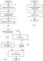
- the method may start in step 500 by establishing a connection with the radio network node 2, when the UE 4 has data that is ready to be transmitted. However the UE 4 may already be connected to the radio network and if so the method starts at step 502.
- the UE 4 is receiving threshold parameter sets Th i from the radio network node 2. As mentioned above each threshold parameter set Th i comprising at least a minimum size limit S i associated with the predefined traffic class i.
- the UE 4 is measuring the amount of data D i that the UE 4 has ready to transmit.
- the measured amount of data may be stored in the memory 36 or in any data buffer of the UE 4.
- the UE 4 is comparing the measured amount of data D i with the minimum size limit S i for the traffic class i that the UE 4 is ready to transmit.
- the embodiments depicted in figure 5 and 6 have the above described steps in common.
- the method performed by the UE 4 transmits in step 512 in response thereto the data from the UE 4 to the radio network node 2.
- the measured amount of data D i may also be an aggregate amount of data D i '. In such a case the UE 4 transmits the aggregate amount of data D i ' in case it exceeds the received minimum size limit S i .
- the UE 4 that performs the method also comprises the timer 38.
- the UE 4 starts, in step 510, the timer 38 in case the measured amount of data D i is less than the minimum size limit S i .
- the UE 4 checks if the timer 38 has lapsed. If the timer 38 has lapsed the method continues to step 512 in which the UE 4 transmits the data from the UE 4 to the radio network node 2, as mentioned above. If the timer 38 has not lapsed the UE 4 continues to check the timer 38 until it lapses, after which the UE 4 commences to step 512.
- step 508 If however it is determined in step 508 that the measured amount of data D i exceeds the minimum size limit S i the UE 4 commences to step 514 and stops the timer 38 if the timer is running and then goes to step 512 as already described above.
- step 506 measuring the amount of data that is ready to be transmitted and the comparing step 508 may be performed more or less continuously or with predefined time intervals.
- the UE 4 will immediately commence its connection establishment with the network node 2. If the measured amount of data D i is smaller than the minimum size limit S i the UE 4 starts the timer 38 which when it expires triggers the connection establishment. If more data arrives during the running of the timer 38 the measured amount of data D i is recalculated as the total amount of data and if the recalculated data is larger than or equal with the minimum size limit S i the UE 4 will stop the timer 38 and commence its connection establishment with the network node 2. If the recalculated data is smaller than the minimum size limit S i , no further action is taken since the timer 38 is already running.
- step 602 the network node 2 transmits threshold parameter sets Th i to the UE 4, each threshold parameter set Th i comprising at least a minimum size limit S i associated with respective traffic class i.
- step 604 the network node 2 receives data from the UE 4 in case the measured amount of data D i that the UE 4 is ready to transmit exceeds the transmitted minimum size limit S i .
- transmitting threshold parameter sets may also comprise transmitting a maximum time limit T i associated with respective traffic class i.
- the threshold parameter sets Th i may be transmitted as unicast information to dedicated UEs 4A, 4B or 4C or as broadcast information to all UEs 4.
Landscapes
- Engineering & Computer Science (AREA)
- Computer Networks & Wireless Communication (AREA)
- Signal Processing (AREA)
- Quality & Reliability (AREA)
- Mobile Radio Communication Systems (AREA)
Claims (11)
- Verfahren, ausgeführt in einer Benutzereinrichtung (4), zum periodischen Übertragen von Daten in einer Uplink-Ressource, wobei die Daten zumindest einer ersten vorbestimmten Verkehrsklasse (i) gehören, umfassend:Empfangen (502) zumindest eines ersten Schwellenparametersatzes aus einem Funknetz, wobei der erste Schwellenparametersatz zumindest eine Mindestgrößengrenze umfasst, welche der ersten vorbestimmten Verkehrsklasse zugeordnet ist,Messen (506) einer Datenmenge, welche die Benutzereinrichtung (4) zur Übertragung bereit hat, wobei die Daten unterschiedlichen vorbestimmten Verkehrsklassen gehören und Daten umfassen, welche der ersten vorbestimmten Verkehrsklasse gehören,Berechnen einer aggregierten Menge von gemessenen Daten für unterschiedliche vorbestimmte Verkehrsklassen durch Ausführen einer Summierung der gemessenen Datenmengen, welche einem Untersatz von unterschiedlichen vorbestimmten Verkehrsklassen gehören,Vergleichen (508) der gemessen Datenmengen mit der Mindestgrößengrenze, welche der ersten vorbestimmten Verkehrsklasse zugeordnet ist, undÜbertragen (512) der aggregierten Menge an gemessenen Daten von der Benutzereinrichtung (4) an das Funknetz, im Falle, dass die aggregierte Datenmenge die empfangene Mindestgrößengrenze überschreitet.
- Verfahren nach Anspruch 1, wobei der Schritt des Empfangens (502) des Schwellenparametersatzes vom Funknetz ferner das Empfangen einer maximalen Zeitgrenze umfasst, welche der ersten vorbestimmten Verkehrsklasse zugeordnet ist und ferner umfassend die Schritte des
Startens (510) eines Zeitgebers (38) in der Benutzereinrichtung (4) im Falle, dass die gemessene Datenmenge kleiner als die empfange Mindestgrößengrenze ist, und
Übertragens (512) der Daten, welche der ersten vorbestimmten Verkehrsklasse gehören, von der Benutzereinrichtung (4) an das Funknetz als Reaktion auf das Erreichen durch den Zeitgeber (38) der empfangenen maximalen Zeitgrenze. - Verfahren nach Anspruch 1 oder 2, wobei der Schritt des Messens (506) der Datenmenge, welche die Benutzereinrichtung (4) zur Übertragung bereit hat, in einem Datenpuffer in einer Radio Link Control-Ebene, RLC, ausgeführt wird.
- Verfahren nach einem der vorhergehenden Ansprüche, wobei der erste Schwellenparametersatz als Unicast-Information vom Funknetz empfangen wird.
- Verfahren nach einem der Ansprüche 1 bis 3, wobei der erste Schwellenparametersatz als Broadcast-Information vom Funknetz empfangen wird.
- Benutzereinrichtung (4) zur Verbesserung der Verwendung einer Uplink-Ressource, wobei die Benutzereinrichtung (4) periodisch Daten in einer Uplink-Ressource überträgt, wobei die Daten zumindest einer ersten vorbestimmten Verkehrsklasse gehören, wobei die Benutzereinrichtung (4) umfasst:eine Kommunikationsschnittstelle (32), welche zur drahtlosen Kommunikation ausgebildet ist;einen Prozessor (34); undeinen Speicher (36), welcher Computerprogrammcode speichert, wobei, wenn der Computerprogrammcode in dem Prozessor (34) ausgeführt wird, dieser die Benutzereinrichtung (4) zu Folgendem veranlasst:Empfangen, über die Kommunikationsschnittstelle (32), zumindest eines ersten Schwellenparametersatzes vom Funknetz, wobei der erste Schwellenparametersatz zumindest eine Mindestgrößengrenze umfasst, welche der ersten vorbestimmten Verkehrsklasse zugeordnet ist,Messen einer Datenmenge, welche die Benutzereinrichtung (4) zur Übertragung bereit hat, wobei die Daten unterschiedlichen vorbestimmten Verkehrsklassen gehören, und Daten umfassen, welche der ersten vorbestimmten Verkehrsklasse gehören,Berechnen einer aggregierten Menge von gemessenen Daten von unterschiedlichen vorbestimmten Verkehrsklassen durch Ausführen einer Summierung der gemessenen Datenmenge für alle unterschiedlichen vorbestimmten Verkehrsklassen,Vergleichen der gemessen Datenmenge mit der Mindestgrößengrenze, welche der ersten vorbestimmten Verkehrsklasse zugeordnet ist, undÜbertragen, über die Kommunikationsschnittstelle (32,) der aggregierten Menge an gemessenen Daten von der Benutzereinrichtung (4) zu dem Funknetz, im Falle, dass die aggregierte Datenmenge die empfangene Mindestgrößengrenze überschreitet.
- Benutzereinrichtung (4) nach Anspruch 6, wobei die Benutzereinrichtung (4) ferner dazu veranlasst wird, Folgendes auszuführen:Empfangen, über die Kommunikationsschnittstelle (32), des ersten Schwellenparametersatzes, umfassend eine maximale Zeitgrenze, welche der ersten vorbestimmten Verkehrsklasse zugeordnet ist, undStarten eines Zeitgebers (38), im Falle, dass die Menge an gemessenen Daten kleiner als die empfangene Mindestgrößengrenze ist, undÜbertragen, über die Kommunikationsschnittstelle (32), der Daten, welche der ersten vorbestimmten Verkehrsklasse gehören von der Benutzereinrichtung (4) zum Funknetz als Reaktion auf das Erreichen durch den Zeitgeber (38) der empfangenen maximalen Zeitgrenze.
- Benutzereinrichtung (4) nach Anspruch 6 oder 7, wobei die Benutzereinrichtung (4) ferner dazu veranlasst wird, die Datenmenge zu messen, welche die Benutzereinrichtung (4) zur Übertragung an einen Datenpuffer in einer Radio-Link-Control-Ebene, RLC, bereit hat.
- Benutzereinrichtung (4) nach einem der Ansprüche 6 bis 8, wobei die Benutzereinrichtung (4) ferner dazu veranlasst wird, den ersten Schwellenparametersatz als Unicast-Information vom Funknetz zu empfangen.
- Benutzereinrichtung (4) nach einem der Ansprüche 6 bis 8, wobei die Benutzereinrichtung (4) ferner dazu veranlasst wird, den ersten Schwellenparametersatz als Broadcast-Information vom Funknetz zu empfangen.
- Benutzereinrichtung (4) nach einem der Ansprüche 6 bis 10, wobei die Benutzereinrichtung (4) ein Smartphone, eine mobiles Telefon, ein zellulares Telefon, oder eine Machine-Type-Communication-Vorrichtung, MTC, ist, wie zum Beispiel ein Stromversorgungsmesser oder ein Kühlschrank.
Applications Claiming Priority (1)
| Application Number | Priority Date | Filing Date | Title |
|---|---|---|---|
| PCT/SE2012/051295 WO2014081360A1 (en) | 2012-11-23 | 2012-11-23 | Methods and apparatuses for uplink resource utilization in a telecommunications system |
Publications (2)
| Publication Number | Publication Date |
|---|---|
| EP2923523A1 EP2923523A1 (de) | 2015-09-30 |
| EP2923523B1 true EP2923523B1 (de) | 2018-09-12 |
Family
ID=47356268
Family Applications (1)
| Application Number | Title | Priority Date | Filing Date |
|---|---|---|---|
| EP12799660.1A Not-in-force EP2923523B1 (de) | 2012-11-23 | 2012-11-23 | Verfahren und vorrichtung zur verwendung von uplink-ressourcen in einem telekommunikationssystem |
Country Status (3)
| Country | Link |
|---|---|
| US (1) | US9060375B2 (de) |
| EP (1) | EP2923523B1 (de) |
| WO (1) | WO2014081360A1 (de) |
Families Citing this family (7)
| Publication number | Priority date | Publication date | Assignee | Title |
|---|---|---|---|---|
| US9407563B2 (en) * | 2013-08-12 | 2016-08-02 | Qualcomm Incorporated | Methods and apparatuses for adapting application uplink rate to wireless communications network |
| US20150172066A1 (en) * | 2013-12-13 | 2015-06-18 | Qualcomm Incorporated | Practical implementation aspects of unicast fetch for http streaming over embms |
| WO2016029150A1 (en) * | 2014-08-21 | 2016-02-25 | Seven Networks, Llc | Optimizing network traffic management in a mobile network |
| US10244538B2 (en) | 2016-02-12 | 2019-03-26 | Futurewei Technologies, Inc. | System and method for determining a resource selection technique |
| WO2018103032A1 (en) * | 2016-12-08 | 2018-06-14 | Qualcomm Incorporated | System information delivery |
| WO2019223861A1 (en) * | 2018-05-23 | 2019-11-28 | Nokia Technologies Oy | Increasing number of connected user equipments on radio access network apparatus |
| CA3214157A1 (en) | 2021-03-30 | 2022-10-06 | Jussi-Pekka Koskinen | Methods and apparatuses for controlling small data transmission on uplink |
Family Cites Families (5)
| Publication number | Priority date | Publication date | Assignee | Title |
|---|---|---|---|---|
| KR100567283B1 (ko) * | 1999-07-10 | 2006-04-05 | 유티스타콤코리아 유한회사 | 이동통신 시스템에서 동적 채널 할당방법 |
| GB2405773B (en) * | 2003-09-02 | 2006-11-08 | Siemens Ag | A method of controlling provision of audio communication on a network |
| JP5213724B2 (ja) * | 2006-02-03 | 2013-06-19 | ノキア コーポレイション | ユーザ機器からワイヤレス・ネットワークへ閾値に基づいたバッファ状態報告を提供する装置、方法、およびコンピュータ・プログラム |
| US8588253B2 (en) * | 2008-06-26 | 2013-11-19 | Qualcomm Incorporated | Methods and apparatuses to reduce context switching during data transmission and reception in a multi-processor device |
| US8848548B2 (en) * | 2009-08-04 | 2014-09-30 | Qualcomm Incorporated | Internet radio broadcast using cellular |
-
2012
- 2012-11-23 EP EP12799660.1A patent/EP2923523B1/de not_active Not-in-force
- 2012-11-23 US US13/808,400 patent/US9060375B2/en not_active Expired - Fee Related
- 2012-11-23 WO PCT/SE2012/051295 patent/WO2014081360A1/en not_active Ceased
Non-Patent Citations (1)
| Title |
|---|
| None * |
Also Published As
| Publication number | Publication date |
|---|---|
| WO2014081360A1 (en) | 2014-05-30 |
| EP2923523A1 (de) | 2015-09-30 |
| US9060375B2 (en) | 2015-06-16 |
| US20140148188A1 (en) | 2014-05-29 |
Similar Documents
| Publication | Publication Date | Title |
|---|---|---|
| EP2818017B1 (de) | Verarbeitungszeitabhängige steuerung einer datenblockübertragung | |
| CN110352572B (zh) | 一种在用户设备ue中的方法以及用户设备ue | |
| US20190174349A1 (en) | Congestion control method, base station, and user equipment | |
| EP2761948B1 (de) | Paketablaufsteuerung in kommunikationen | |
| US9060375B2 (en) | Methods and apparatuses for uplink resource utilization in a telecommunications system | |
| CN111819881A (zh) | 服务质量(qos)拥塞控制处理 | |
| EP3335359B1 (de) | Verfahren und vorrichtung zur getrennten planung von uplink-daten- und referenzsignalübertragungen in einem kommunikationsnetzwerk | |
| CN103384394A (zh) | 用户设备耗电、耗电配置参数处理方法及装置 | |
| CN103037524A (zh) | Tdd上下行子帧比例的双周期动态配置方法、基站、系统和通信设备 | |
| CN103856312B (zh) | 载波激活和去激活的方法、设备 | |
| US10039141B2 (en) | Event-triggered mode switching for a mobile terminal | |
| WO2010090566A1 (en) | Method and arrangement in a wireless communication system | |
| EP3272182B1 (de) | Ereignisausgelöste modusumschaltung für ein mobiles endgerät | |
| US8838130B2 (en) | Method and arrangement in a wireless communication system | |
| EP3278616B1 (de) | Netzwerkknoten und davon durchgeführtes verfahren zur unterstützung des voip-dienstes einer drahtlosen vorrichtung | |
| EP3520502B1 (de) | Uplink-leistungspriorisierung für kurze tti | |
| WO2019197027A1 (en) | Methods and apparatuses for selective modulation and coding scheme (mcs) exclusion | |
| US20150092679A1 (en) | Enhancement of the Implementation of the High Speed Cell FACH/RACH Feature | |
| CN114208385B (zh) | 拥塞管理 | |
| US10231248B2 (en) | Methods and devices for managing connectivity for a service | |
| EP2629580B1 (de) | Verfahren zur Handhabung der Übertragungskonfiguration einer Kommunikationsvorrichtung und Kommunikationssystem |
Legal Events
| Date | Code | Title | Description |
|---|---|---|---|
| PUAI | Public reference made under article 153(3) epc to a published international application that has entered the european phase |
Free format text: ORIGINAL CODE: 0009012 |
|
| 17P | Request for examination filed |
Effective date: 20150415 |
|
| AK | Designated contracting states |
Kind code of ref document: A1 Designated state(s): AL AT BE BG CH CY CZ DE DK EE ES FI FR GB GR HR HU IE IS IT LI LT LU LV MC MK MT NL NO PL PT RO RS SE SI SK SM TR |
|
| AX | Request for extension of the european patent |
Extension state: BA ME |
|
| DAX | Request for extension of the european patent (deleted) | ||
| 17Q | First examination report despatched |
Effective date: 20170413 |
|
| GRAP | Despatch of communication of intention to grant a patent |
Free format text: ORIGINAL CODE: EPIDOSNIGR1 |
|
| INTG | Intention to grant announced |
Effective date: 20180326 |
|
| GRAJ | Information related to disapproval of communication of intention to grant by the applicant or resumption of examination proceedings by the epo deleted |
Free format text: ORIGINAL CODE: EPIDOSDIGR1 |
|
| GRAP | Despatch of communication of intention to grant a patent |
Free format text: ORIGINAL CODE: EPIDOSNIGR1 |
|
| INTG | Intention to grant announced |
Effective date: 20180621 |
|
| GRAS | Grant fee paid |
Free format text: ORIGINAL CODE: EPIDOSNIGR3 |
|
| GRAA | (expected) grant |
Free format text: ORIGINAL CODE: 0009210 |
|
| AK | Designated contracting states |
Kind code of ref document: B1 Designated state(s): AL AT BE BG CH CY CZ DE DK EE ES FI FR GB GR HR HU IE IS IT LI LT LU LV MC MK MT NL NO PL PT RO RS SE SI SK SM TR |
|
| REG | Reference to a national code |
Ref country code: GB Ref legal event code: FG4D |
|
| REG | Reference to a national code |
Ref country code: CH Ref legal event code: EP |
|
| REG | Reference to a national code |
Ref country code: IE Ref legal event code: FG4D |
|
| REG | Reference to a national code |
Ref country code: DE Ref legal event code: R096 Ref document number: 602012051047 Country of ref document: DE |
|
| REG | Reference to a national code |
Ref country code: AT Ref legal event code: REF Ref document number: 1042114 Country of ref document: AT Kind code of ref document: T Effective date: 20181015 |
|
| REG | Reference to a national code |
Ref country code: NL Ref legal event code: FP |
|
| REG | Reference to a national code |
Ref country code: LT Ref legal event code: MG4D |
|
| PG25 | Lapsed in a contracting state [announced via postgrant information from national office to epo] |
Ref country code: RS Free format text: LAPSE BECAUSE OF FAILURE TO SUBMIT A TRANSLATION OF THE DESCRIPTION OR TO PAY THE FEE WITHIN THE PRESCRIBED TIME-LIMIT Effective date: 20180912 Ref country code: LT Free format text: LAPSE BECAUSE OF FAILURE TO SUBMIT A TRANSLATION OF THE DESCRIPTION OR TO PAY THE FEE WITHIN THE PRESCRIBED TIME-LIMIT Effective date: 20180912 Ref country code: BG Free format text: LAPSE BECAUSE OF FAILURE TO SUBMIT A TRANSLATION OF THE DESCRIPTION OR TO PAY THE FEE WITHIN THE PRESCRIBED TIME-LIMIT Effective date: 20181212 Ref country code: FI Free format text: LAPSE BECAUSE OF FAILURE TO SUBMIT A TRANSLATION OF THE DESCRIPTION OR TO PAY THE FEE WITHIN THE PRESCRIBED TIME-LIMIT Effective date: 20180912 Ref country code: GR Free format text: LAPSE BECAUSE OF FAILURE TO SUBMIT A TRANSLATION OF THE DESCRIPTION OR TO PAY THE FEE WITHIN THE PRESCRIBED TIME-LIMIT Effective date: 20181213 Ref country code: NO Free format text: LAPSE BECAUSE OF FAILURE TO SUBMIT A TRANSLATION OF THE DESCRIPTION OR TO PAY THE FEE WITHIN THE PRESCRIBED TIME-LIMIT Effective date: 20181212 Ref country code: SE Free format text: LAPSE BECAUSE OF FAILURE TO SUBMIT A TRANSLATION OF THE DESCRIPTION OR TO PAY THE FEE WITHIN THE PRESCRIBED TIME-LIMIT Effective date: 20180912 |
|
| PG25 | Lapsed in a contracting state [announced via postgrant information from national office to epo] |
Ref country code: HR Free format text: LAPSE BECAUSE OF FAILURE TO SUBMIT A TRANSLATION OF THE DESCRIPTION OR TO PAY THE FEE WITHIN THE PRESCRIBED TIME-LIMIT Effective date: 20180912 Ref country code: LV Free format text: LAPSE BECAUSE OF FAILURE TO SUBMIT A TRANSLATION OF THE DESCRIPTION OR TO PAY THE FEE WITHIN THE PRESCRIBED TIME-LIMIT Effective date: 20180912 Ref country code: AL Free format text: LAPSE BECAUSE OF FAILURE TO SUBMIT A TRANSLATION OF THE DESCRIPTION OR TO PAY THE FEE WITHIN THE PRESCRIBED TIME-LIMIT Effective date: 20180912 |
|
| REG | Reference to a national code |
Ref country code: AT Ref legal event code: MK05 Ref document number: 1042114 Country of ref document: AT Kind code of ref document: T Effective date: 20180912 |
|
| PG25 | Lapsed in a contracting state [announced via postgrant information from national office to epo] |
Ref country code: CZ Free format text: LAPSE BECAUSE OF FAILURE TO SUBMIT A TRANSLATION OF THE DESCRIPTION OR TO PAY THE FEE WITHIN THE PRESCRIBED TIME-LIMIT Effective date: 20180912 Ref country code: IT Free format text: LAPSE BECAUSE OF FAILURE TO SUBMIT A TRANSLATION OF THE DESCRIPTION OR TO PAY THE FEE WITHIN THE PRESCRIBED TIME-LIMIT Effective date: 20180912 Ref country code: RO Free format text: LAPSE BECAUSE OF FAILURE TO SUBMIT A TRANSLATION OF THE DESCRIPTION OR TO PAY THE FEE WITHIN THE PRESCRIBED TIME-LIMIT Effective date: 20180912 Ref country code: AT Free format text: LAPSE BECAUSE OF FAILURE TO SUBMIT A TRANSLATION OF THE DESCRIPTION OR TO PAY THE FEE WITHIN THE PRESCRIBED TIME-LIMIT Effective date: 20180912 Ref country code: IS Free format text: LAPSE BECAUSE OF FAILURE TO SUBMIT A TRANSLATION OF THE DESCRIPTION OR TO PAY THE FEE WITHIN THE PRESCRIBED TIME-LIMIT Effective date: 20190112 Ref country code: ES Free format text: LAPSE BECAUSE OF FAILURE TO SUBMIT A TRANSLATION OF THE DESCRIPTION OR TO PAY THE FEE WITHIN THE PRESCRIBED TIME-LIMIT Effective date: 20180912 Ref country code: EE Free format text: LAPSE BECAUSE OF FAILURE TO SUBMIT A TRANSLATION OF THE DESCRIPTION OR TO PAY THE FEE WITHIN THE PRESCRIBED TIME-LIMIT Effective date: 20180912 |
|
| PG25 | Lapsed in a contracting state [announced via postgrant information from national office to epo] |
Ref country code: SM Free format text: LAPSE BECAUSE OF FAILURE TO SUBMIT A TRANSLATION OF THE DESCRIPTION OR TO PAY THE FEE WITHIN THE PRESCRIBED TIME-LIMIT Effective date: 20180912 Ref country code: PT Free format text: LAPSE BECAUSE OF FAILURE TO SUBMIT A TRANSLATION OF THE DESCRIPTION OR TO PAY THE FEE WITHIN THE PRESCRIBED TIME-LIMIT Effective date: 20190112 Ref country code: SK Free format text: LAPSE BECAUSE OF FAILURE TO SUBMIT A TRANSLATION OF THE DESCRIPTION OR TO PAY THE FEE WITHIN THE PRESCRIBED TIME-LIMIT Effective date: 20180912 |
|
| REG | Reference to a national code |
Ref country code: DE Ref legal event code: R097 Ref document number: 602012051047 Country of ref document: DE |
|
| REG | Reference to a national code |
Ref country code: CH Ref legal event code: PL |
|
| PLBE | No opposition filed within time limit |
Free format text: ORIGINAL CODE: 0009261 |
|
| STAA | Information on the status of an ep patent application or granted ep patent |
Free format text: STATUS: NO OPPOSITION FILED WITHIN TIME LIMIT |
|
| PG25 | Lapsed in a contracting state [announced via postgrant information from national office to epo] |
Ref country code: DK Free format text: LAPSE BECAUSE OF FAILURE TO SUBMIT A TRANSLATION OF THE DESCRIPTION OR TO PAY THE FEE WITHIN THE PRESCRIBED TIME-LIMIT Effective date: 20180912 Ref country code: LU Free format text: LAPSE BECAUSE OF NON-PAYMENT OF DUE FEES Effective date: 20181123 Ref country code: MC Free format text: LAPSE BECAUSE OF FAILURE TO SUBMIT A TRANSLATION OF THE DESCRIPTION OR TO PAY THE FEE WITHIN THE PRESCRIBED TIME-LIMIT Effective date: 20180912 |
|
| REG | Reference to a national code |
Ref country code: BE Ref legal event code: MM Effective date: 20181130 |
|
| 26N | No opposition filed |
Effective date: 20190613 |
|
| REG | Reference to a national code |
Ref country code: IE Ref legal event code: MM4A |
|
| PG25 | Lapsed in a contracting state [announced via postgrant information from national office to epo] |
Ref country code: LI Free format text: LAPSE BECAUSE OF NON-PAYMENT OF DUE FEES Effective date: 20181130 Ref country code: SI Free format text: LAPSE BECAUSE OF FAILURE TO SUBMIT A TRANSLATION OF THE DESCRIPTION OR TO PAY THE FEE WITHIN THE PRESCRIBED TIME-LIMIT Effective date: 20180912 Ref country code: CH Free format text: LAPSE BECAUSE OF NON-PAYMENT OF DUE FEES Effective date: 20181130 |
|
| PG25 | Lapsed in a contracting state [announced via postgrant information from national office to epo] |
Ref country code: IE Free format text: LAPSE BECAUSE OF NON-PAYMENT OF DUE FEES Effective date: 20181123 Ref country code: FR Free format text: LAPSE BECAUSE OF NON-PAYMENT OF DUE FEES Effective date: 20181130 |
|
| PG25 | Lapsed in a contracting state [announced via postgrant information from national office to epo] |
Ref country code: BE Free format text: LAPSE BECAUSE OF NON-PAYMENT OF DUE FEES Effective date: 20181130 |
|
| PG25 | Lapsed in a contracting state [announced via postgrant information from national office to epo] |
Ref country code: MT Free format text: LAPSE BECAUSE OF NON-PAYMENT OF DUE FEES Effective date: 20181123 |
|
| PG25 | Lapsed in a contracting state [announced via postgrant information from national office to epo] |
Ref country code: TR Free format text: LAPSE BECAUSE OF FAILURE TO SUBMIT A TRANSLATION OF THE DESCRIPTION OR TO PAY THE FEE WITHIN THE PRESCRIBED TIME-LIMIT Effective date: 20180912 |
|
| PG25 | Lapsed in a contracting state [announced via postgrant information from national office to epo] |
Ref country code: CY Free format text: LAPSE BECAUSE OF FAILURE TO SUBMIT A TRANSLATION OF THE DESCRIPTION OR TO PAY THE FEE WITHIN THE PRESCRIBED TIME-LIMIT Effective date: 20180912 Ref country code: HU Free format text: LAPSE BECAUSE OF FAILURE TO SUBMIT A TRANSLATION OF THE DESCRIPTION OR TO PAY THE FEE WITHIN THE PRESCRIBED TIME-LIMIT; INVALID AB INITIO Effective date: 20121123 Ref country code: MK Free format text: LAPSE BECAUSE OF NON-PAYMENT OF DUE FEES Effective date: 20180912 |
|
| PG25 | Lapsed in a contracting state [announced via postgrant information from national office to epo] |
Ref country code: PL Free format text: LAPSE BECAUSE OF FAILURE TO SUBMIT A TRANSLATION OF THE DESCRIPTION OR TO PAY THE FEE WITHIN THE PRESCRIBED TIME-LIMIT Effective date: 20180912 |
|
| PGFP | Annual fee paid to national office [announced via postgrant information from national office to epo] |
Ref country code: NL Payment date: 20201126 Year of fee payment: 9 |
|
| PGFP | Annual fee paid to national office [announced via postgrant information from national office to epo] |
Ref country code: DE Payment date: 20201127 Year of fee payment: 9 |
|
| PGFP | Annual fee paid to national office [announced via postgrant information from national office to epo] |
Ref country code: GB Payment date: 20211129 Year of fee payment: 10 |
|
| REG | Reference to a national code |
Ref country code: DE Ref legal event code: R119 Ref document number: 602012051047 Country of ref document: DE |
|
| REG | Reference to a national code |
Ref country code: NL Ref legal event code: MM Effective date: 20211201 |
|
| PG25 | Lapsed in a contracting state [announced via postgrant information from national office to epo] |
Ref country code: NL Free format text: LAPSE BECAUSE OF NON-PAYMENT OF DUE FEES Effective date: 20211201 |
|
| PG25 | Lapsed in a contracting state [announced via postgrant information from national office to epo] |
Ref country code: DE Free format text: LAPSE BECAUSE OF NON-PAYMENT OF DUE FEES Effective date: 20220601 |
|
| GBPC | Gb: european patent ceased through non-payment of renewal fee |
Effective date: 20221123 |
|
| PG25 | Lapsed in a contracting state [announced via postgrant information from national office to epo] |
Ref country code: GB Free format text: LAPSE BECAUSE OF NON-PAYMENT OF DUE FEES Effective date: 20221123 |