EP2923621B1 - Elektrohaushaltsgerät zur essenszubereitung, das einen behälter umfasst, der mit einem abnehmbaren deckel verschlossen ist, der mit einer sicherheitsvorrichtung kombiniert ist - Google Patents
Elektrohaushaltsgerät zur essenszubereitung, das einen behälter umfasst, der mit einem abnehmbaren deckel verschlossen ist, der mit einer sicherheitsvorrichtung kombiniert ist Download PDFInfo
- Publication number
- EP2923621B1 EP2923621B1 EP15160372.7A EP15160372A EP2923621B1 EP 2923621 B1 EP2923621 B1 EP 2923621B1 EP 15160372 A EP15160372 A EP 15160372A EP 2923621 B1 EP2923621 B1 EP 2923621B1
- Authority
- EP
- European Patent Office
- Prior art keywords
- container
- cover
- electrical appliance
- household electrical
- lid
- Prior art date
- Legal status (The legal status is an assumption and is not a legal conclusion. Google has not performed a legal analysis and makes no representation as to the accuracy of the status listed.)
- Active
Links
Images

Classifications
-
- A—HUMAN NECESSITIES
- A47—FURNITURE; DOMESTIC ARTICLES OR APPLIANCES; COFFEE MILLS; SPICE MILLS; SUCTION CLEANERS IN GENERAL
- A47J—KITCHEN EQUIPMENT; COFFEE MILLS; SPICE MILLS; APPARATUS FOR MAKING BEVERAGES
- A47J43/00—Implements for preparing or holding food, not provided for in other groups of this subclass
- A47J43/04—Machines for domestic use not covered elsewhere, e.g. for grinding, mixing, stirring, kneading, emulsifying, whipping or beating foodstuffs, e.g. power-driven
- A47J43/07—Parts or details, e.g. mixing tools, whipping tools
- A47J43/075—Safety devices
- A47J43/0761—Safety devices for machines with tools driven from the lower side
- A47J43/0772—Safety devices for machines with tools driven from the lower side activated by the proper positioning of the cover
- A47J43/0777—Safety devices for machines with tools driven from the lower side activated by the proper positioning of the cover in which the activating element on the cover transmits a signal to a safety device in the base element via the mixing bowl removably seated on this base element, e.g. pin on the cover moves a pushrod in the bowl handle to operate safety switch in the base element
Definitions
- the present invention relates to the general technical field of electrical household appliances for culinary preparation comprising a receptacle receiving a working tool rotated by a motor and a cover removably closing the receptacle, the receptacle comprising a detecting element co-operating with a safety device for prohibiting the operation of the engine when the lid is not locked on the container, and relates more particularly to an electrical household appliance for culinary preparation in which the detection element is movable between a rest position to which it is brought by return means and an operating position to which it is brought by an actuating member carried by the cover when the latter is locked on the container.
- a food preparation apparatus comprising a container containing a working tool rotated by a motor, the container being closed by a removable cover.
- the lid is provided with a safety tab which protrudes laterally from the lid and actuates, via a transmission rod carried by the container, a switch integrated in the motor housing of the device.
- An apparatus provided with such a device has the advantage of great safety of use by preventing the operation of the motor in the absence of the cover.
- the cover equipping such a device has the disadvantage of being fragile at the safety tab, the latter can break during the fall of the lid, resulting in the impossibility of using the device.
- the breakage of the safety tab of the cover is at the origin of many returns in after-sales service.
- an object of the present invention is to remedy these disadvantages by providing a food preparation apparatus comprising a safety device preventing the operation of the apparatus in the absence of the lid which is both simple and economical to achieve and a greater robustness.
- the invention relates to an electrical household appliance for culinary preparation
- a receptacle receiving a working tool rotated by a motor and a lid for releasably closing the receptacle
- the receptacle comprising a detecting element co-operating with a safety device preventing operation of the motor when the lid is not locked on the container, the detection element being movable between a rest position to which it is brought by return means and an operating position towards which it is brought by an actuating member carried by the lid when the latter is locked on the container
- the lid comprises a peripheral skirt extending over the entire circumference of the lid, the skirt having an inner wall coming into look at an external wall of the container when the lid closes the container, and in e that the actuating member protrudes from the inner wall of the skirt of the lid.
- Such an apparatus has the advantage of having an actuating member which projects towards the inside of the lid so that the actuating member is protected by the skirt of the lid in case of fall of the lid. This produces an apparatus in which the risk of breakage of the actuating member is greatly reduced.
- the lid is locked by rotation on the container, for example by a bayonet type connection.
- Such locking by rotation of the lid has the advantage of being simple and ergonomic.
- the inner wall of the skirt of the cover comprises at least two locking elements cooperating with at least two complementary locking elements formed on the outer wall of the container to form the bayonet connection, the organ actuator being constituted by one of the locking elements.
- the lid thus produced has the advantage of having a locking element having both the function of ensuring the holding of the lid on the container and of acting, as an actuating member, on the element of detection of the safety device, so that the reliability of these two functions can be ensured economically by providing a robust locking element.
- the locking elements are regularly distributed over the peripheral skirt of the lid so that the lid can be locked on the container in several orientations, each locking element of the lid having a shape adapted to act on the detection element and move it towards the operating position when it is opposite the latter when closing the lid.
- Such a feature has the advantage of allowing the locking of the lid on the container in several directions, always ensuring the activation of the safety device, for greater ergonomics of use of the device.
- the cover comprises at least four locking elements and preferably six locking elements.
- Such a characteristic makes it possible to offer at least four possible locking orientations and preferably six, for greater ergonomics of use.
- the container comprises a handle comprising a base which is fixed along the outer wall of the container, the detection element being constituted by a detection rod mounted movably in translation in the base of the container. the handle.
- the container comprises a complementary locking element near the handle.
- the container comprises a complementary locking element extending opposite the detection rod, said complementary locking element comprising an opening in which the end of the detection rod is engaged. when she occupies the resting position.
- the handle comprises a notch for receiving the skirt of the lid at the upper end of the handle, the notch being adapted to allow the passage of the locking elements of the lid.
- the container is removably mounted on a housing enclosing the motor, the housing comprising a base on which the container comes to rest.
- the safety device comprises a security piece which is brought to a safety position by the detection rod when the container, provided with its lid in the closed position, is arranged on the base, the safety element acting on a switch to allow the operation of the motor only when the safety piece is in the safety position.
- the security piece comprises at least two detection cams opening in two distinct locations of the base of the housing.
- Such a feature allows actuation of the security piece when the container occupies two distinct positions on the housing.
- the cover comprises a central portion and a peripheral ring made of different materials, the ring incorporating the skirt of the cover.
- Such a characteristic makes it possible to make the crown of the lid, coming into contact with the container, in a material distinct from that used for the central part in order to ensure better sliding of the lid during the rotation. for locking / unlocking.
- the central part of the lid is made of transparent or translucent material, advantageously of plastic material of SAN type (styrene-acrylonitrile copolymer), and the ring is made of opaque material, preferably plastic material of ABS type (acrylonitrile butadiene styrene).
- SAN styrene-acrylonitrile copolymer
- ABS acrylonitrile butadiene styrene
- the crown is assembled by overmoulding on the central part of the lid.
- Such a feature allows a simple and economical way to ensure reliable assembly of the crown on the central portion.
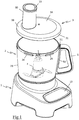
- the figure 1 illustrates a food preparation robot, particularly for chopping or slicing, comprising a housing 1 supporting a removable container 2 comprising a casing 20 of circular section closed at its upper end by a removable cover 3, the container 2 receiving a rotary working tool 4 , illustrated in dotted line on figure 1 disposed in the bottom of the container 2.
- the lid 3 comprises a feed chute 30 for introducing food into the container 2, advantageously receiving a pusher 33, and comprises a peripheral skirt 31 extending over the entire circumference of the lid 3, covering the upper end of the envelope 20 of the container.
- the container 2 is advantageously provided with a handle 5 comprising a fixing base 50 extending substantially vertically along the casing 20, the base 50 comprising a notch 51 at its upper end in which is engaged the skirt 31 of the lid when the lid 3 comes to close the container 2.
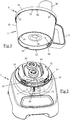
- the housing 1 comprises a circular receiving base 10, on which the container 2 comes to rest, the receiving base 10 comprising a central driver 61 and an eccentric driver 62 surrounded by a U-shaped guideway 11.
- the container 2 comprises a central chimney 21 extending from the bottom of the container to allow, in a manner known per se, the coupling of the working tool 4 with the central trainer 61, and comprises a skirt 22 which extends vertically under the bottom of the container 2 to engage around the guideway 11 of the base 10 of reception, the skirt 22 comprising an inner wall supporting locking lugs 23 engaging in grooves 12 formed in edge of the guiding cavity to make a bayonet type connection ensuring the attachment of the container 2 on the housing 1.
- the housing 1 encloses an electric motor 6 of universal type, represented schematically dotted on the figure 4 , whose operation is controlled by a control panel 13 disposed on the front face of the housing 1.
- the power of the motor 6 is advantageously between 500W and 1100W and its nominal speed is of the order of 16000 rpm, the eccentric driver 62 being preferably mounted directly on the output shaft of the electric motor 6 and the central driver 61 being driven via a speed reducer ensuring a reduction of the speed of more than ten times relative to the speed of rotation of the motor 6.
- the apparatus comprises a safety device preventing the operation of the engine 6 when the container is not closed by its cover, this safety device comprising a security part 7, shown in dotted line on the figure 2 , able to move vertically in the housing 1 against a return spring 70 to actuate a switch 71 disposed on the motor supply circuit 6.
- the security part 7 comprises two cams 72 arranged at 90 ° to each other with respect to the center of the base 10, the two cams 72 opening through two slots in the guide groove 11 .
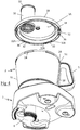
- the safety device also comprises a detection rod 8, visible on the figures 3 and 5 , which extends along the outer wall of the container 2, being disposed inside a cavity in the base of the handle 5, the detection rod 8 having a lower end provided with a finger activation 80 coming opposite one of the cams 72 of the security part 7 when the container 2 is locked on the base 10, the presence of the two cams 72 on the base allowing the cooperation of the detection rod 8 with the security part 7 when the container is placed on the base 10 with the handle 5 of the container respectively shifted 45 ° to the right or 45 ° to the left relative to the control panel 13.
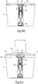
- the detection rod 8 is, in a manner known per se, mounted movable in translation between a rest position, illustrated in FIGS. figures 5 and 8B in which the activation finger 80 does not exert pressure on the cam 72 of the security part 7 when the container 2 is locked on the base 10, and a operating position, illustrated on the figures 6 and 8A in which the activation finger 80 exerts a pressure on the cam 72 to bring the security piece 7 into a safety position where it actuates the switch 71 when the container 2 is locked on the base 10, the rod detection 8 being brought back to the rest position by a return spring 81.
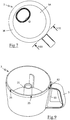
- the lid 3 is locked on the container 2 by means of a bayonet type connection advantageously comprising six L-shaped locking ribs 32 projecting from an inner wall of the skirt 31, these ribs 32 cooperating with ribs 24 complementary locking, of rectangular shape, formed on the outer wall of the container 2, the six ribs 32 of the lid and the six ribs 24 of the container being evenly distributed on the lid 3 and on the container 2 so that the lid 3 can be locked on the container 2 in six different orientations.
- a bayonet type connection advantageously comprising six L-shaped locking ribs 32 projecting from an inner wall of the skirt 31, these ribs 32 cooperating with ribs 24 complementary locking, of rectangular shape, formed on the outer wall of the container 2, the six ribs 32 of the lid and the six ribs 24 of the container being evenly distributed on the lid 3 and on the container 2 so that the lid 3 can be locked on the container 2 in six different orientations.
- the cover 3 comprises a transparent central portion 3A made by molding in SAN type plastic material, and a peripheral ring 3B made of ABS plastic material which is overmolded on the central portion 3A, the ring 3B incorporating in particular the skirt 31 of the lid 3 and the ribs 32 of the lid.
- one of the ribs 24 of the container 2 is preferably arranged facing the handle 5, this rib 24 extending through the notch 51 formed at the upper end of the handle 5 and advantageously having an opening 25 view of the detection rod 8 in which a tapered upper end 82 of the detection rod 8 can engage when the detection rod 8 reaches the rest position shown in FIG. Figure 8B .
- the ribs 32 for locking the lid 3 comprise a lower surface which is preferably flush with the lower plane of the skirt 31, each rib 32 comprising a chamfered end 32A facilitating the engagement of the rib 32 under the rib 24 of the container during its rotation in the direction of closing, and an opposite end comprising a return of material extending vertically towards the inside of the lid 3 to form a stop 32B which stops the rotation of the lid 3 at the end of the locking stroke.
- each rib 32 for locking the lid 3 comprises a transverse groove 36 adapted to receive the upper end 82 of the detection rod when the lid is at the end of the locking stroke.
- the user When the user wishes to use the apparatus, he places the lid 3 on the container 2 without worrying about the orientation of the lid 3 with respect to the container 2, then turns the lid 3 in the locking direction so that that, if it is not already done, the ribs 32 of the lid are engaged between the ribs 24 of the container and then under the ribs 24, thus preventing any lifting of the lid 3.
- the user can then operate the apparatus by selecting the desired command on the control panel 13, the operation of the engine 6 being made possible by the operation of the switch 71 by the security piece 7.
- the insertion of the upper end 82 of the detection rod into the transverse groove 36 formed on the lid 3 has the advantage of immobilizing the lid in the locking position, thus avoiding an involuntary unlocking of the cover 3, for example under the effect of the vibrations generated by the operation of the apparatus.
- Such an apparatus therefore has the advantage of being robust, the ribs of the cover acting on the sensor rod being disposed inside the cover being protected from shocks by the presence of the skirt.
- the lid of such a device has the advantage of having good ergonomics of use, the user does not have to worry about the orientation of the lid when it wishes to lock on the container, each ribs of the cover that can cooperate with the sensor rod to move the latter to the operating position.
- the ribs 24 of rectangular shape of the container equipping the apparatus according to the invention may be replaced by locking lugs 25, of a width of the order of 2 mm, in which the ribs 32 of the lid 3 lock come engage, the lugs 25 being disposed on the outer wall of the container so that they abut against the stops 32B of the cover 3 when the upper end 82 of the detection rod 8 is engaged in the groove 36 the rib 32 of the cover lying opposite the handle 5.
- Such an embodiment has the advantage of facilitating the engagement of the lid on the container by offering a larger angular range where the ribs 32 of the lid 3 can engage between the lugs 25 of the container 2 prior to the rotation of the lid 3 for locking.
Landscapes
- Engineering & Computer Science (AREA)
- Mechanical Engineering (AREA)
- Food Science & Technology (AREA)
- Closures For Containers (AREA)
- Food-Manufacturing Devices (AREA)
Claims (11)
- Elektrisches Haushaltsgerät zur Nahrungsmittelzubereitung, aufweisend einen Behälter (2), in dem ein Arbeitswerkzeug (4) aufgenommen ist, das von einem Motor (6) in Rotation angetrieben wird, und eine Abdeckung (3), die den Behälter (2) abnehmbar verschließt, wobei der Behälter (2) ein Erfassungselement (8) aufweist, das mit einer Sicherheitsvorrichtung zusammenwirkt, die den Betrieb des Motors (6) verhindert, wenn die Abdeckung (3) nicht auf dem Behälter (2) verriegelt ist, wobei das Erfassungselement (8) zwischen einer Ruheposition, in die es durch Rückstellmittel (81) gebracht wird, und einer Betriebsposition bewegbar ist, in die es durch ein Betätigungsorgan (32) gebracht wird, das von der Abdeckung (3) getragen wird, wenn die letztere durch Drehung auf dem Behälter (2) verriegelt ist, wobei die Abdeckung (3) eine umlaufende Schürze (31) aufweist, die sich über den gesamten Umfang der Abdeckung (3) erstreckt, wobei die Schürze (31) eine Innenwand aufweist, die einer Außenwand des Behälters (2) zugewandt ist, wenn die Abdeckung den Behälter verschließt, wobei das Betätigungsorgan (32) über der Innenwand der Schürze (31) der Abdeckung (3) hervorsteht, dadurch gekennzeichnet, dass die Innenwand der Schürze (31) der Abdeckung (3) mindestens zwei Verriegelungselemente (32) aufweist, die mit mindestens zwei komplementären Verriegelungselementen (24) zusammenwirken, die auf der Außenwand des Behälters (2) aufgenommen sind, um eine Verbindung vom Bajonetttyp zu bilden, und dass das Betätigungsorgan aus einem der Verriegelungselemente (32) besteht.
- Elektrisches Haushaltsgerät nach Anspruch 1, dadurch gekennzeichnet, dass die Verriegelungselemente (32) gleichmäßig über die umlaufende Schürze (31) der Abdeckung verteilt sind, so dass die Abdeckung (3) in mehreren Orientierungen auf dem Behälter (2) verriegelt werden kann, und dass jedes Verriegelungselement (32) der Abdeckung eine Form aufweist, die angepasst ist, um auf das Erfassungselement (8) einzuwirken und es in die Betriebsposition zu bewegen, wenn es sich gegenüber der letzteren während des Schließens der Abdeckung (3) befindet.
- Elektrisches Haushaltsgerät nach Anspruch 2, dadurch gekennzeichnet, dass die Abdeckung mindestens vier Verriegelungselemente (32) und vorzugsweise sechs Verriegelungselemente (32) aufweist.
- Elektrisches Haushaltsgerät nach einem der Ansprüche 1 bis 3, dadurch gekennzeichnet, dass der Behälter (2) einen Griff (5) aufweist, der ein Unterteil (50) umfasst, das entlang der Außenwand des Behälters (2) befestigt ist, wobei das Erfassungselement (8) aus einer Erfassungsstange besteht, die in dem Unterteil des Griffs (5) translationsbeweglich angebracht ist.
- Elektrisches Haushaltsgerät nach Anspruch 4, dadurch gekennzeichnet, dass der Griff (5) eine Kerbe (51) zur Aufnahme der Schürze (31) der Abdeckung an dem oberen Ende des Griffs (5) aufweist, wobei die Kerbe angepasst ist, um den Durchgang der Verriegelungselemente (32) der Abdeckung (3) zu ermöglichen.
- Elektrisches Haushaltsgerät nach einem der Ansprüche 1 bis 5, dadurch gekennzeichnet, dass der Behälter (2) an einem den Motor umschließenden Gehäuse (1) lösbar angebracht ist, wobei das Gehäuse (1) einen Sockel (10) aufweist, auf dem der Behälter (2) aufliegt.
- Elektrisches Haushaltsgerät nach Anspruch 6, dadurch gekennzeichnet, dass die Sicherheitsvorrichtung ein Sicherheitsteil (7) aufweist, das durch den Erfassungsstab (8) in eine Sicherheitsposition gebracht wird, wenn der Behälter (2), der mit seiner Abdeckung (3) in der geschlossenen Position versehen ist, auf dem Sockel (10) angeordnet ist, wobei das Sicherheitsteil (7) auf einen Schalter (71) einwirkt, um den Betrieb des Motors (6) nur dann zu ermöglichen, wenn das Sicherheitsteil (7) die Sicherheitsposition einnimmt.
- Elektrisches Haushaltsgerät nach Anspruch 7, dadurch gekennzeichnet, dass das Sicherheitsteil (7) mindestens zwei Erfassungsnocken (72) aufweist, die an zwei verschiedenen Stellen des Sockels (10) des Gehäuses (1) münden.
- Elektrisches Haushaltsgerät nach einem der Ansprüche 1 bis 8, dadurch gekennzeichnet, dass die Abdeckung (3) einen mittleren Abschnitt (3A) und einen aus verschiedenen Materialien hergestellten umlaufenden Ring (3B) aufweist, wobei in dem Ring (3B) die Schürze (31) der Abdeckung integriert ist.
- Elektrisches Haushaltsgerät nach Anspruch 9, dadurch gekennzeichnet, dass der mittlere Abschnitt (3A) der Abdeckung aus transparentem oder durchscheinendem Material, vorteilhafterweise aus einem Kunststoffmaterial vom Typ SAN (Styrol-Acrylnitril-Copolymer), hergestellt ist, und dass der Ring (3B) aus opakem Material, vorteilhafterweise einem Kunststoffmaterial vom Typ ABS (Acrylnitril-Butadien-Styrol) hergestellt ist.
- Elektrisches Haushaltsgerät nach einem der Ansprüche 9 bis 10, dadurch gekennzeichnet, dass der Ring (3B) durch Umspritzen an dem mittleren Abschnitt (3A) der Abdeckung (3) angefügt ist.
Applications Claiming Priority (1)
| Application Number | Priority Date | Filing Date | Title |
|---|---|---|---|
| FR1452490A FR3019024B1 (fr) | 2014-03-25 | 2014-03-25 | Appareil electromenager de preparation culinaire comprenant un recipient ferme par un couvercle amovible cooperant avec un dispositif de securite |
Publications (2)
| Publication Number | Publication Date |
|---|---|
| EP2923621A1 EP2923621A1 (de) | 2015-09-30 |
| EP2923621B1 true EP2923621B1 (de) | 2018-06-20 |
Family
ID=50639785
Family Applications (1)
| Application Number | Title | Priority Date | Filing Date |
|---|---|---|---|
| EP15160372.7A Active EP2923621B1 (de) | 2014-03-25 | 2015-03-23 | Elektrohaushaltsgerät zur essenszubereitung, das einen behälter umfasst, der mit einem abnehmbaren deckel verschlossen ist, der mit einer sicherheitsvorrichtung kombiniert ist |
Country Status (3)
| Country | Link |
|---|---|
| EP (1) | EP2923621B1 (de) |
| CN (1) | CN104939697B (de) |
| FR (1) | FR3019024B1 (de) |
Families Citing this family (10)
| Publication number | Priority date | Publication date | Assignee | Title |
|---|---|---|---|---|
| FR3043320B1 (fr) | 2015-11-09 | 2017-12-01 | Seb Sa | Appareil electromenager de preparation culinaire comprenant un dispositif d'entrainement d'un outil de travail rotatif muni d'un systeme de freinage |
| FR3057752B1 (fr) * | 2016-10-24 | 2021-05-28 | Seb Sa | Appareil electromenager de preparation culinaire comportant un couvercle intermediaire |
| CN107280519A (zh) * | 2017-07-25 | 2017-10-24 | 江门市鸿裕达电机电器制造有限公司 | 带有保护装置的搅拌机 |
| FR3071711B1 (fr) * | 2017-09-29 | 2019-11-22 | Seb S.A. | Appareil electromenager de preparation culinaire chauffant comportant un dispositif de securite |
| DE202019100726U1 (de) * | 2019-02-08 | 2019-02-21 | De'longhi Braun Household Gmbh | Behälter mit universell einsetzbarer nicht sichtbarer Griffbefestigung zur Verwendung mit Haushaltsgeräten |
| DE102019211309A1 (de) * | 2019-07-30 | 2021-02-04 | BSH Hausgeräte GmbH | Küchenmaschine mit Verriegelungssystem |
| CN110313854B (zh) * | 2019-08-23 | 2021-10-26 | 莱克电气股份有限公司 | 一种料理机 |
| ES3033646T3 (en) * | 2020-03-06 | 2025-08-06 | Vorwerk Co Interholding | Preparation container comprising a locking device |
| GB2598966A (en) * | 2020-09-22 | 2022-03-23 | Kenwood Ltd | Food processor attachment mechanism |
| ES2944759A1 (es) * | 2021-12-23 | 2023-06-23 | Cecotec Res And Development S L | Dispositivo de seguridad para robot de cocina |
Family Cites Families (13)
| Publication number | Priority date | Publication date | Assignee | Title |
|---|---|---|---|---|
| FR2129193A6 (de) * | 1971-03-18 | 1972-10-27 | Verdun Pierre | |
| DE3319513C2 (de) * | 1983-05-28 | 1985-03-28 | Geka-Werk Reinhold Klein KG, 3573 Gemünden/Wohra | Küchenmaschine |
| FR2729588B1 (fr) * | 1995-01-24 | 1997-06-13 | Moulinex Sa | Appareil menager a couteau rotatif, tel qu'un hachoir |
| TR200100946T2 (tr) * | 1998-10-06 | 2001-07-23 | Arno Sa | Kasesinin tepesi açıkken blenderin-mutfak robotunun çalışmasını önleyen emniyet sistemi |
| FR2856910B1 (fr) * | 2003-07-02 | 2005-08-19 | Seb Sa | Appareil electromenager pour la preparation des aliments comportant une poignee perfectionnee |
| FR2866541B1 (fr) * | 2004-02-20 | 2006-04-14 | Seb Sa | Appareil electromenager de preparation culinaire |
| FR2888741B1 (fr) * | 2005-07-21 | 2007-08-24 | Seb Sa | Accessoire de preparation culinaire a ouil rotatif muni d'un dispositif de securite particulier |
| FR2890552B1 (fr) * | 2005-09-15 | 2007-10-12 | Hameur Sa | Dispositif couvercle de cuve d'un appareil de traitement d'aliments |
| FR2939298B1 (fr) * | 2008-12-10 | 2011-01-07 | Seb Sa | Appareil electromenager de preparation culinaire comportant un boitier supportant un bras de transmission amovible au dessus d'un recipient de travail |
| CA2714947A1 (en) * | 2009-09-21 | 2011-03-21 | Conair Corporation | Food processor bowl cover clamp |
| FR2960759B1 (fr) * | 2010-06-08 | 2012-06-15 | Seb Sa | Appareil electromenager de preparation culinaire comportant un recipient de travail ferme par un couvercle amovible |
| FR2965161B1 (fr) * | 2010-09-24 | 2012-10-05 | Seb Sa | Appareil electromenager de preparation culinaire comportant un recipient renfermant un outil coupant entraine en rotation par un moteur |
| FR2965162B1 (fr) * | 2010-09-24 | 2012-10-05 | Seb Sa | Appareil electromenager de preparation culinaire comportant un recipient renfermant un outil coupant entraine en rotation par un moteur |
-
2014
- 2014-03-25 FR FR1452490A patent/FR3019024B1/fr not_active Expired - Fee Related
-
2015
- 2015-03-18 CN CN201510119410.2A patent/CN104939697B/zh active Active
- 2015-03-23 EP EP15160372.7A patent/EP2923621B1/de active Active
Non-Patent Citations (1)
| Title |
|---|
| None * |
Also Published As
| Publication number | Publication date |
|---|---|
| FR3019024B1 (fr) | 2017-02-17 |
| CN104939697A (zh) | 2015-09-30 |
| CN104939697B (zh) | 2018-12-11 |
| FR3019024A1 (fr) | 2015-10-02 |
| EP2923621A1 (de) | 2015-09-30 |
Similar Documents
| Publication | Publication Date | Title |
|---|---|---|
| EP2923621A1 (de) | Elektrohaushaltsgerät zur essenszubereitung, das einen behälter umfasst, der mit einem abnehmbaren deckel verschlossen ist, der mit einer sicherheitsvorrichtung kombiniert ist | |
| EP2934252B1 (de) | Elektrische speisenzubereitungsvorrichtung mit einem arbeitsbehälter und vorrichtung zum erwärmen des inhalts des arbeitsbehälters | |
| EP2687132B1 (de) | Druckkochgerät mit verbesserter Bedienungsvorrichtung | |
| EP2509478B1 (de) | Haushaltskochgerät mit arbeitsgefäss mit elektrischem widerstand | |
| EP2394547B1 (de) | Elektrohaushaltsgerät zur Essenszubereitung, das aus einem mit einem abnehmbaren Deckel verschlossenen Arbeitsbehälter besteht | |
| EP2368470B1 (de) | Elektrohaushaltsgerät zur Essenzubereitung, das ein Gehäuse mit einer Arbeitsschüsselhalterung und einem Zerkleinerungswerkzeug zum Einführen in die Schüssel umfasst | |
| WO2009010665A2 (fr) | Appareil de preparation culinaire muni d'un dispositif de securite | |
| EP2651273A1 (de) | Elektrische küchenmaschine mit einem sockel für eine schüssel und einem fix mit dem sockel verbundenen arm | |
| EP1191870B1 (de) | Elektrisches handrühr- und -mixgerät mit sicherheitseinrichtung | |
| EP2433533B1 (de) | Haushaltsgerät mit einem Gefäß, das ein von einem Motor angetriebenes Schneidewerkzeug umfasst | |
| EP3038508A1 (de) | Elektrische lebensmittelzubereitungsvorrichtung mit einem arbeitswerkzeug zur vorübergehenden verbindung mit einem antriebsmechanismus | |
| EP2433534B1 (de) | Haushaltsgerät mit einem Gefäß, das ein von einem Motor angetriebenes Schneidewerkzeug umfasst | |
| FR2939298A1 (fr) | Appareil electromenager de preparation culinaire comportant un boitier supportant un bras de transmission amovible au dessus d'un recipient de travail | |
| EP2651272B1 (de) | Elektrische küchenmaschine mit einem sockel für eine mit einem abnehmbarem deckel verschliessbare schüssel | |
| FR2908620A1 (fr) | Appareil de preparation culinaire comportant des moyens particuliers d'immobilisation du recipient | |
| WO2009106707A1 (fr) | Appareil electromenager de preparation culinaire comprenant un boitier comportant plusieurs entraineurs au niveau d'un socle de reception | |
| FR2957508A1 (fr) | Appareil electromenager de preparation culinaire comportant un boitier moteur destine a recevoir differents types d'accessoires amovibles | |
| EP1745728B1 (de) | Küchengerät mit rotierendem Werkzeug und spezieller Sicherheitsvorrichtung | |
| EP0681307B1 (de) | Sicherheitsvorrichtung für ein elektrisches bewegliches Bauelement und Grill mit einer derartigen Vorrichtung | |
| EP1370171B1 (de) | Elektrische küchenmaschine mit einem drehwerkzeug und einer doppelten sicherheitsvorrichtung | |
| EP2011424A2 (de) | Haushaltsgerät, das einen Arbeitsbehälter mit einer Öffnung umfasst, über die ein abnehmbarer Weghahn angeschlossen werden kann | |
| EP1151835A1 (de) | Elektrogerät zur Lebensmittelbearbeitung mit Druckorgan |
Legal Events
| Date | Code | Title | Description |
|---|---|---|---|
| PUAI | Public reference made under article 153(3) epc to a published international application that has entered the european phase |
Free format text: ORIGINAL CODE: 0009012 |
|
| AK | Designated contracting states |
Kind code of ref document: A1 Designated state(s): AL AT BE BG CH CY CZ DE DK EE ES FI FR GB GR HR HU IE IS IT LI LT LU LV MC MK MT NL NO PL PT RO RS SE SI SK SM TR |
|
| AX | Request for extension of the european patent |
Extension state: BA ME |
|
| 17P | Request for examination filed |
Effective date: 20160330 |
|
| RBV | Designated contracting states (corrected) |
Designated state(s): AL AT BE BG CH CY CZ DE DK EE ES FI FR GB GR HR HU IE IS IT LI LT LU LV MC MK MT NL NO PL PT RO RS SE SI SK SM TR |
|
| RAP1 | Party data changed (applicant data changed or rights of an application transferred) |
Owner name: SEB S.A. |
|
| GRAP | Despatch of communication of intention to grant a patent |
Free format text: ORIGINAL CODE: EPIDOSNIGR1 |
|
| STAA | Information on the status of an ep patent application or granted ep patent |
Free format text: STATUS: GRANT OF PATENT IS INTENDED |
|
| INTG | Intention to grant announced |
Effective date: 20180110 |
|
| GRAS | Grant fee paid |
Free format text: ORIGINAL CODE: EPIDOSNIGR3 |
|
| GRAA | (expected) grant |
Free format text: ORIGINAL CODE: 0009210 |
|
| STAA | Information on the status of an ep patent application or granted ep patent |
Free format text: STATUS: THE PATENT HAS BEEN GRANTED |
|
| AK | Designated contracting states |
Kind code of ref document: B1 Designated state(s): AL AT BE BG CH CY CZ DE DK EE ES FI FR GB GR HR HU IE IS IT LI LT LU LV MC MK MT NL NO PL PT RO RS SE SI SK SM TR |
|
| REG | Reference to a national code |
Ref country code: GB Ref legal event code: FG4D Free format text: NOT ENGLISH |
|
| REG | Reference to a national code |
Ref country code: IE Ref legal event code: FG4D Free format text: LANGUAGE OF EP DOCUMENT: FRENCH |
|
| REG | Reference to a national code |
Ref country code: AT Ref legal event code: REF Ref document number: 1009972 Country of ref document: AT Kind code of ref document: T Effective date: 20180715 |
|
| REG | Reference to a national code |
Ref country code: DE Ref legal event code: R096 Ref document number: 602015012429 Country of ref document: DE |
|
| REG | Reference to a national code |
Ref country code: NL Ref legal event code: MP Effective date: 20180620 |
|
| PG25 | Lapsed in a contracting state [announced via postgrant information from national office to epo] |
Ref country code: BG Free format text: LAPSE BECAUSE OF FAILURE TO SUBMIT A TRANSLATION OF THE DESCRIPTION OR TO PAY THE FEE WITHIN THE PRESCRIBED TIME-LIMIT Effective date: 20180920 Ref country code: LT Free format text: LAPSE BECAUSE OF FAILURE TO SUBMIT A TRANSLATION OF THE DESCRIPTION OR TO PAY THE FEE WITHIN THE PRESCRIBED TIME-LIMIT Effective date: 20180620 Ref country code: FI Free format text: LAPSE BECAUSE OF FAILURE TO SUBMIT A TRANSLATION OF THE DESCRIPTION OR TO PAY THE FEE WITHIN THE PRESCRIBED TIME-LIMIT Effective date: 20180620 Ref country code: NO Free format text: LAPSE BECAUSE OF FAILURE TO SUBMIT A TRANSLATION OF THE DESCRIPTION OR TO PAY THE FEE WITHIN THE PRESCRIBED TIME-LIMIT Effective date: 20180920 Ref country code: SE Free format text: LAPSE BECAUSE OF FAILURE TO SUBMIT A TRANSLATION OF THE DESCRIPTION OR TO PAY THE FEE WITHIN THE PRESCRIBED TIME-LIMIT Effective date: 20180620 |
|
| REG | Reference to a national code |
Ref country code: LT Ref legal event code: MG4D |
|
| PG25 | Lapsed in a contracting state [announced via postgrant information from national office to epo] |
Ref country code: RS Free format text: LAPSE BECAUSE OF FAILURE TO SUBMIT A TRANSLATION OF THE DESCRIPTION OR TO PAY THE FEE WITHIN THE PRESCRIBED TIME-LIMIT Effective date: 20180620 Ref country code: LV Free format text: LAPSE BECAUSE OF FAILURE TO SUBMIT A TRANSLATION OF THE DESCRIPTION OR TO PAY THE FEE WITHIN THE PRESCRIBED TIME-LIMIT Effective date: 20180620 Ref country code: HR Free format text: LAPSE BECAUSE OF FAILURE TO SUBMIT A TRANSLATION OF THE DESCRIPTION OR TO PAY THE FEE WITHIN THE PRESCRIBED TIME-LIMIT Effective date: 20180620 Ref country code: GR Free format text: LAPSE BECAUSE OF FAILURE TO SUBMIT A TRANSLATION OF THE DESCRIPTION OR TO PAY THE FEE WITHIN THE PRESCRIBED TIME-LIMIT Effective date: 20180921 |
|
| REG | Reference to a national code |
Ref country code: AT Ref legal event code: MK05 Ref document number: 1009972 Country of ref document: AT Kind code of ref document: T Effective date: 20180620 |
|
| PG25 | Lapsed in a contracting state [announced via postgrant information from national office to epo] |
Ref country code: NL Free format text: LAPSE BECAUSE OF FAILURE TO SUBMIT A TRANSLATION OF THE DESCRIPTION OR TO PAY THE FEE WITHIN THE PRESCRIBED TIME-LIMIT Effective date: 20180620 |
|
| PG25 | Lapsed in a contracting state [announced via postgrant information from national office to epo] |
Ref country code: SK Free format text: LAPSE BECAUSE OF FAILURE TO SUBMIT A TRANSLATION OF THE DESCRIPTION OR TO PAY THE FEE WITHIN THE PRESCRIBED TIME-LIMIT Effective date: 20180620 Ref country code: RO Free format text: LAPSE BECAUSE OF FAILURE TO SUBMIT A TRANSLATION OF THE DESCRIPTION OR TO PAY THE FEE WITHIN THE PRESCRIBED TIME-LIMIT Effective date: 20180620 Ref country code: CZ Free format text: LAPSE BECAUSE OF FAILURE TO SUBMIT A TRANSLATION OF THE DESCRIPTION OR TO PAY THE FEE WITHIN THE PRESCRIBED TIME-LIMIT Effective date: 20180620 Ref country code: PL Free format text: LAPSE BECAUSE OF FAILURE TO SUBMIT A TRANSLATION OF THE DESCRIPTION OR TO PAY THE FEE WITHIN THE PRESCRIBED TIME-LIMIT Effective date: 20180620 Ref country code: AT Free format text: LAPSE BECAUSE OF FAILURE TO SUBMIT A TRANSLATION OF THE DESCRIPTION OR TO PAY THE FEE WITHIN THE PRESCRIBED TIME-LIMIT Effective date: 20180620 Ref country code: EE Free format text: LAPSE BECAUSE OF FAILURE TO SUBMIT A TRANSLATION OF THE DESCRIPTION OR TO PAY THE FEE WITHIN THE PRESCRIBED TIME-LIMIT Effective date: 20180620 Ref country code: IS Free format text: LAPSE BECAUSE OF FAILURE TO SUBMIT A TRANSLATION OF THE DESCRIPTION OR TO PAY THE FEE WITHIN THE PRESCRIBED TIME-LIMIT Effective date: 20181020 |
|
| PG25 | Lapsed in a contracting state [announced via postgrant information from national office to epo] |
Ref country code: SM Free format text: LAPSE BECAUSE OF FAILURE TO SUBMIT A TRANSLATION OF THE DESCRIPTION OR TO PAY THE FEE WITHIN THE PRESCRIBED TIME-LIMIT Effective date: 20180620 Ref country code: ES Free format text: LAPSE BECAUSE OF FAILURE TO SUBMIT A TRANSLATION OF THE DESCRIPTION OR TO PAY THE FEE WITHIN THE PRESCRIBED TIME-LIMIT Effective date: 20180620 |
|
| REG | Reference to a national code |
Ref country code: DE Ref legal event code: R097 Ref document number: 602015012429 Country of ref document: DE |
|
| PLBE | No opposition filed within time limit |
Free format text: ORIGINAL CODE: 0009261 |
|
| STAA | Information on the status of an ep patent application or granted ep patent |
Free format text: STATUS: NO OPPOSITION FILED WITHIN TIME LIMIT |
|
| 26N | No opposition filed |
Effective date: 20190321 |
|
| PG25 | Lapsed in a contracting state [announced via postgrant information from national office to epo] |
Ref country code: DK Free format text: LAPSE BECAUSE OF FAILURE TO SUBMIT A TRANSLATION OF THE DESCRIPTION OR TO PAY THE FEE WITHIN THE PRESCRIBED TIME-LIMIT Effective date: 20180620 |
|
| PG25 | Lapsed in a contracting state [announced via postgrant information from national office to epo] |
Ref country code: SI Free format text: LAPSE BECAUSE OF FAILURE TO SUBMIT A TRANSLATION OF THE DESCRIPTION OR TO PAY THE FEE WITHIN THE PRESCRIBED TIME-LIMIT Effective date: 20180620 |
|
| REG | Reference to a national code |
Ref country code: DE Ref legal event code: R119 Ref document number: 602015012429 Country of ref document: DE |
|
| PG25 | Lapsed in a contracting state [announced via postgrant information from national office to epo] |
Ref country code: MC Free format text: LAPSE BECAUSE OF FAILURE TO SUBMIT A TRANSLATION OF THE DESCRIPTION OR TO PAY THE FEE WITHIN THE PRESCRIBED TIME-LIMIT Effective date: 20180620 |
|
| REG | Reference to a national code |
Ref country code: CH Ref legal event code: PL |
|
| PG25 | Lapsed in a contracting state [announced via postgrant information from national office to epo] |
Ref country code: AL Free format text: LAPSE BECAUSE OF FAILURE TO SUBMIT A TRANSLATION OF THE DESCRIPTION OR TO PAY THE FEE WITHIN THE PRESCRIBED TIME-LIMIT Effective date: 20180620 Ref country code: LU Free format text: LAPSE BECAUSE OF NON-PAYMENT OF DUE FEES Effective date: 20190323 |
|
| PG25 | Lapsed in a contracting state [announced via postgrant information from national office to epo] |
Ref country code: CH Free format text: LAPSE BECAUSE OF NON-PAYMENT OF DUE FEES Effective date: 20190331 Ref country code: DE Free format text: LAPSE BECAUSE OF NON-PAYMENT OF DUE FEES Effective date: 20191001 Ref country code: IE Free format text: LAPSE BECAUSE OF NON-PAYMENT OF DUE FEES Effective date: 20190323 Ref country code: LI Free format text: LAPSE BECAUSE OF NON-PAYMENT OF DUE FEES Effective date: 20190331 |
|
| PG25 | Lapsed in a contracting state [announced via postgrant information from national office to epo] |
Ref country code: PT Free format text: LAPSE BECAUSE OF FAILURE TO SUBMIT A TRANSLATION OF THE DESCRIPTION OR TO PAY THE FEE WITHIN THE PRESCRIBED TIME-LIMIT Effective date: 20181022 Ref country code: MT Free format text: LAPSE BECAUSE OF FAILURE TO SUBMIT A TRANSLATION OF THE DESCRIPTION OR TO PAY THE FEE WITHIN THE PRESCRIBED TIME-LIMIT Effective date: 20180620 |
|
| PG25 | Lapsed in a contracting state [announced via postgrant information from national office to epo] |
Ref country code: CY Free format text: LAPSE BECAUSE OF FAILURE TO SUBMIT A TRANSLATION OF THE DESCRIPTION OR TO PAY THE FEE WITHIN THE PRESCRIBED TIME-LIMIT Effective date: 20180620 |
|
| PG25 | Lapsed in a contracting state [announced via postgrant information from national office to epo] |
Ref country code: HU Free format text: LAPSE BECAUSE OF FAILURE TO SUBMIT A TRANSLATION OF THE DESCRIPTION OR TO PAY THE FEE WITHIN THE PRESCRIBED TIME-LIMIT; INVALID AB INITIO Effective date: 20150323 |
|
| PG25 | Lapsed in a contracting state [announced via postgrant information from national office to epo] |
Ref country code: MK Free format text: LAPSE BECAUSE OF FAILURE TO SUBMIT A TRANSLATION OF THE DESCRIPTION OR TO PAY THE FEE WITHIN THE PRESCRIBED TIME-LIMIT Effective date: 20180620 |
|
| P01 | Opt-out of the competence of the unified patent court (upc) registered |
Effective date: 20230517 |
|
| PGFP | Annual fee paid to national office [announced via postgrant information from national office to epo] |
Ref country code: BE Payment date: 20250324 Year of fee payment: 11 |
|
| PGFP | Annual fee paid to national office [announced via postgrant information from national office to epo] |
Ref country code: GB Payment date: 20260323 Year of fee payment: 12 |
|
| PGFP | Annual fee paid to national office [announced via postgrant information from national office to epo] |
Ref country code: IT Payment date: 20260310 Year of fee payment: 12 |
|
| PGFP | Annual fee paid to national office [announced via postgrant information from national office to epo] |
Ref country code: FR Payment date: 20260330 Year of fee payment: 12 |
|
| PGFP | Annual fee paid to national office [announced via postgrant information from national office to epo] |
Ref country code: TR Payment date: 20260311 Year of fee payment: 12 |