EP2923714A1 - Durch hautkontakt ausgelöste Autoinjektor - Google Patents
Durch hautkontakt ausgelöste Autoinjektor Download PDFInfo
- Publication number
- EP2923714A1 EP2923714A1 EP14162454.4A EP14162454A EP2923714A1 EP 2923714 A1 EP2923714 A1 EP 2923714A1 EP 14162454 A EP14162454 A EP 14162454A EP 2923714 A1 EP2923714 A1 EP 2923714A1
- Authority
- EP
- European Patent Office
- Prior art keywords
- case
- plunger
- shroud
- needle
- autoinjector
- Prior art date
- Legal status (The legal status is an assumption and is not a legal conclusion. Google has not performed a legal analysis and makes no representation as to the accuracy of the status listed.)
- Ceased
Links
- 229940090047 auto-injector Drugs 0.000 title claims abstract description 132
- 230000001960 triggered effect Effects 0.000 title 1
- 239000003814 drug Substances 0.000 claims abstract description 40
- 230000001681 protective effect Effects 0.000 claims description 66
- 238000003780 insertion Methods 0.000 claims description 11
- 230000037431 insertion Effects 0.000 claims description 11
- 230000007246 mechanism Effects 0.000 description 56
- JUFFVKRROAPVBI-PVOYSMBESA-N chembl1210015 Chemical compound C([C@@H](C(=O)N[C@@H]([C@@H](C)CC)C(=O)N[C@@H](CCC(O)=O)C(=O)N[C@@H](CC=1C2=CC=CC=C2NC=1)C(=O)N[C@@H](CC(C)C)C(=O)N[C@@H](CCCCN)C(=O)N[C@@H](CC(=O)N[C@H]1[C@@H]([C@@H](O)[C@H](O[C@H]2[C@@H]([C@@H](O)[C@@H](O)[C@@H](CO[C@]3(O[C@@H](C[C@H](O)[C@H](O)CO)[C@H](NC(C)=O)[C@@H](O)C3)C(O)=O)O2)O)[C@@H](CO)O1)NC(C)=O)C(=O)NCC(=O)NCC(=O)N1[C@@H](CCC1)C(=O)N[C@@H](CO)C(=O)N[C@@H](CO)C(=O)NCC(=O)N[C@@H](C)C(=O)N1[C@@H](CCC1)C(=O)N1[C@@H](CCC1)C(=O)N1[C@@H](CCC1)C(=O)N[C@@H](CO)C(N)=O)NC(=O)[C@H](CC(C)C)NC(=O)[C@H](CCCNC(N)=N)NC(=O)[C@@H](NC(=O)[C@H](C)NC(=O)[C@H](CCC(O)=O)NC(=O)[C@H](CCC(O)=O)NC(=O)[C@H](CCC(O)=O)NC(=O)[C@H](CCSC)NC(=O)[C@H](CCC(N)=O)NC(=O)[C@H](CCCCN)NC(=O)[C@H](CO)NC(=O)[C@H](CC(C)C)NC(=O)[C@H](CC(O)=O)NC(=O)[C@H](CO)NC(=O)[C@@H](NC(=O)[C@H](CC=1C=CC=CC=1)NC(=O)[C@@H](NC(=O)CNC(=O)[C@H](CCC(O)=O)NC(=O)CNC(=O)[C@@H](N)CC=1NC=NC=1)[C@@H](C)O)[C@@H](C)O)C(C)C)C1=CC=CC=C1 JUFFVKRROAPVBI-PVOYSMBESA-N 0.000 description 54
- 108010011459 Exenatide Proteins 0.000 description 50
- 229960001519 exenatide Drugs 0.000 description 50
- 238000002347 injection Methods 0.000 description 27
- 239000007924 injection Substances 0.000 description 27
- 101000976075 Homo sapiens Insulin Proteins 0.000 description 22
- QEFRNWWLZKMPFJ-YGVKFDHGSA-N L-methionine S-oxide Chemical compound CS(=O)CC[C@H](N)C(O)=O QEFRNWWLZKMPFJ-YGVKFDHGSA-N 0.000 description 22
- PBGKTOXHQIOBKM-FHFVDXKLSA-N insulin (human) Chemical compound C([C@@H](C(=O)N[C@@H](CC(C)C)C(=O)N[C@H]1CSSC[C@H]2C(=O)N[C@H](C(=O)N[C@@H](CO)C(=O)N[C@H](C(=O)N[C@H](C(N[C@@H](CO)C(=O)N[C@@H](CC(C)C)C(=O)N[C@@H](CC=3C=CC(O)=CC=3)C(=O)N[C@@H](CCC(N)=O)C(=O)N[C@@H](CC(C)C)C(=O)N[C@@H](CCC(O)=O)C(=O)N[C@@H](CC(N)=O)C(=O)N[C@@H](CC=3C=CC(O)=CC=3)C(=O)N[C@@H](CSSC[C@H](NC(=O)[C@H](C(C)C)NC(=O)[C@H](CC(C)C)NC(=O)[C@H](CC=3C=CC(O)=CC=3)NC(=O)[C@H](CC(C)C)NC(=O)[C@H](C)NC(=O)[C@H](CCC(O)=O)NC(=O)[C@H](C(C)C)NC(=O)[C@H](CC(C)C)NC(=O)[C@H](CC=3NC=NC=3)NC(=O)[C@H](CO)NC(=O)CNC1=O)C(=O)NCC(=O)N[C@@H](CCC(O)=O)C(=O)N[C@@H](CCCNC(N)=N)C(=O)NCC(=O)N[C@@H](CC=1C=CC=CC=1)C(=O)N[C@@H](CC=1C=CC=CC=1)C(=O)N[C@@H](CC=1C=CC(O)=CC=1)C(=O)N[C@@H]([C@@H](C)O)C(=O)N1[C@@H](CCC1)C(=O)N[C@@H](CCCCN)C(=O)N[C@@H]([C@@H](C)O)C(O)=O)C(=O)N[C@@H](CC(N)=O)C(O)=O)=O)CSSC[C@@H](C(N2)=O)NC(=O)[C@H](CCC(N)=O)NC(=O)[C@H](CCC(O)=O)NC(=O)[C@H](C(C)C)NC(=O)[C@@H](NC(=O)CN)[C@@H](C)CC)[C@@H](C)CC)[C@@H](C)O)NC(=O)[C@H](CCC(N)=O)NC(=O)[C@H](CC(N)=O)NC(=O)[C@@H](NC(=O)[C@@H](N)CC=1C=CC=CC=1)C(C)C)C1=CN=CN1 PBGKTOXHQIOBKM-FHFVDXKLSA-N 0.000 description 21
- 239000012634 fragment Substances 0.000 description 10
- 235000001014 amino acid Nutrition 0.000 description 9
- 150000001413 amino acids Chemical class 0.000 description 9
- 150000003839 salts Chemical class 0.000 description 8
- 239000000427 antigen Substances 0.000 description 7
- 102000036639 antigens Human genes 0.000 description 7
- 108091007433 antigens Proteins 0.000 description 7
- 150000001875 compounds Chemical class 0.000 description 7
- 108090000765 processed proteins & peptides Proteins 0.000 description 5
- 108060003951 Immunoglobulin Proteins 0.000 description 4
- 206010012601 diabetes mellitus Diseases 0.000 description 4
- 102000018358 immunoglobulin Human genes 0.000 description 4
- 238000000034 method Methods 0.000 description 4
- 239000004033 plastic Substances 0.000 description 4
- 108010047041 Complementarity Determining Regions Proteins 0.000 description 3
- 238000007792 addition Methods 0.000 description 3
- 210000003719 b-lymphocyte Anatomy 0.000 description 3
- 150000004676 glycans Chemical class 0.000 description 3
- 229940088597 hormone Drugs 0.000 description 3
- 239000005556 hormone Substances 0.000 description 3
- NOESYZHRGYRDHS-UHFFFAOYSA-N insulin Chemical class N1C(=O)C(NC(=O)C(CCC(N)=O)NC(=O)C(CCC(O)=O)NC(=O)C(C(C)C)NC(=O)C(NC(=O)CN)C(C)CC)CSSCC(C(NC(CO)C(=O)NC(CC(C)C)C(=O)NC(CC=2C=CC(O)=CC=2)C(=O)NC(CCC(N)=O)C(=O)NC(CC(C)C)C(=O)NC(CCC(O)=O)C(=O)NC(CC(N)=O)C(=O)NC(CC=2C=CC(O)=CC=2)C(=O)NC(CSSCC(NC(=O)C(C(C)C)NC(=O)C(CC(C)C)NC(=O)C(CC=2C=CC(O)=CC=2)NC(=O)C(CC(C)C)NC(=O)C(C)NC(=O)C(CCC(O)=O)NC(=O)C(C(C)C)NC(=O)C(CC(C)C)NC(=O)C(CC=2NC=NC=2)NC(=O)C(CO)NC(=O)CNC2=O)C(=O)NCC(=O)NC(CCC(O)=O)C(=O)NC(CCCNC(N)=N)C(=O)NCC(=O)NC(CC=3C=CC=CC=3)C(=O)NC(CC=3C=CC=CC=3)C(=O)NC(CC=3C=CC(O)=CC=3)C(=O)NC(C(C)O)C(=O)N3C(CCC3)C(=O)NC(CCCCN)C(=O)NC(C)C(O)=O)C(=O)NC(CC(N)=O)C(O)=O)=O)NC(=O)C(C(C)CC)NC(=O)C(CO)NC(=O)C(C(C)O)NC(=O)C1CSSCC2NC(=O)C(CC(C)C)NC(=O)C(NC(=O)C(CCC(N)=O)NC(=O)C(CC(N)=O)NC(=O)C(NC(=O)C(N)CC=1C=CC=CC=1)C(C)C)CC1=CN=CN1 NOESYZHRGYRDHS-UHFFFAOYSA-N 0.000 description 3
- 239000003055 low molecular weight heparin Substances 0.000 description 3
- 229940127215 low-molecular weight heparin Drugs 0.000 description 3
- 238000012986 modification Methods 0.000 description 3
- 230000004048 modification Effects 0.000 description 3
- 238000004806 packaging method and process Methods 0.000 description 3
- 229920001282 polysaccharide Polymers 0.000 description 3
- 239000005017 polysaccharide Substances 0.000 description 3
- 230000008569 process Effects 0.000 description 3
- 238000013519 translation Methods 0.000 description 3
- 208000004476 Acute Coronary Syndrome Diseases 0.000 description 2
- 208000002249 Diabetes Complications Diseases 0.000 description 2
- 206010012689 Diabetic retinopathy Diseases 0.000 description 2
- 108010088406 Glucagon-Like Peptides Proteins 0.000 description 2
- 241000124008 Mammalia Species 0.000 description 2
- 239000002253 acid Substances 0.000 description 2
- 230000004913 activation Effects 0.000 description 2
- 150000001447 alkali salts Chemical class 0.000 description 2
- 230000008878 coupling Effects 0.000 description 2
- 238000010168 coupling process Methods 0.000 description 2
- 238000005859 coupling reaction Methods 0.000 description 2
- 125000000151 cysteine group Chemical group N[C@@H](CS)C(=O)* 0.000 description 2
- 230000029087 digestion Effects 0.000 description 2
- 229940079593 drug Drugs 0.000 description 2
- LMHMJYMCGJNXRS-IOPUOMRJSA-N exendin-3 Chemical compound C([C@@H](C(=O)N[C@@H]([C@@H](C)CC)C(=O)N[C@@H](CCC(O)=O)C(=O)N[C@@H](CC=1C2=CC=CC=C2NC=1)C(=O)N[C@@H](CC(C)C)C(=O)N[C@@H](CCCCN)C(=O)N[C@@H](CC(N)=O)C(=O)NCC(=O)NCC(=O)N1[C@@H](CCC1)C(=O)N[C@@H](CO)C(=O)N[C@@H](CO)C(=O)NCC(=O)N[C@@H](C)C(=O)N1[C@@H](CCC1)C(=O)N1[C@@H](CCC1)C(=O)N1[C@@H](CCC1)C(=O)N[C@@H](CO)C(N)=O)NC(=O)[C@H](CC(C)C)NC(=O)[C@H](CCCNC(N)=N)NC(=O)[C@@H](NC(=O)[C@H](C)NC(=O)[C@H](CCC(O)=O)NC(=O)[C@H](CCC(O)=O)NC(=O)[C@H](CCC(O)=O)NC(=O)[C@H](CCSC)NC(=O)[C@H](CCC(N)=O)NC(=O)[C@H](CCCCN)NC(=O)[C@H](CO)NC(=O)[C@H](CC(C)C)NC(=O)[C@H](CC(O)=O)NC(=O)[C@H](CO)NC(=O)[C@@H](NC(=O)[C@H](CC=1C=CC=CC=1)NC(=O)[C@@H](NC(=O)CNC(=O)[C@H](CC(O)=O)NC(=O)[C@H](CO)NC(=O)[C@@H](N)CC=1N=CNC=1)[C@H](C)O)[C@H](C)O)C(C)C)C1=CC=CC=C1 LMHMJYMCGJNXRS-IOPUOMRJSA-N 0.000 description 2
- 238000004519 manufacturing process Methods 0.000 description 2
- 239000000203 mixture Substances 0.000 description 2
- 239000000178 monomer Substances 0.000 description 2
- 102000004196 processed proteins & peptides Human genes 0.000 description 2
- 238000011321 prophylaxis Methods 0.000 description 2
- 239000012453 solvate Substances 0.000 description 2
- 238000003860 storage Methods 0.000 description 2
- 238000011282 treatment Methods 0.000 description 2
- KIUKXJAPPMFGSW-DNGZLQJQSA-N (2S,3S,4S,5R,6R)-6-[(2S,3R,4R,5S,6R)-3-Acetamido-2-[(2S,3S,4R,5R,6R)-6-[(2R,3R,4R,5S,6R)-3-acetamido-2,5-dihydroxy-6-(hydroxymethyl)oxan-4-yl]oxy-2-carboxy-4,5-dihydroxyoxan-3-yl]oxy-5-hydroxy-6-(hydroxymethyl)oxan-4-yl]oxy-3,4,5-trihydroxyoxane-2-carboxylic acid Chemical compound CC(=O)N[C@H]1[C@H](O)O[C@H](CO)[C@@H](O)[C@@H]1O[C@H]1[C@H](O)[C@@H](O)[C@H](O[C@H]2[C@@H]([C@@H](O[C@H]3[C@@H]([C@@H](O)[C@H](O)[C@H](O3)C(O)=O)O)[C@H](O)[C@@H](CO)O2)NC(C)=O)[C@@H](C(O)=O)O1 KIUKXJAPPMFGSW-DNGZLQJQSA-N 0.000 description 1
- 125000004169 (C1-C6) alkyl group Chemical group 0.000 description 1
- 125000001831 (C6-C10) heteroaryl group Chemical group 0.000 description 1
- 208000035285 Allergic Seasonal Rhinitis Diseases 0.000 description 1
- QGZKDVFQNNGYKY-UHFFFAOYSA-O Ammonium Chemical compound [NH4+] QGZKDVFQNNGYKY-UHFFFAOYSA-O 0.000 description 1
- 206010002383 Angina Pectoris Diseases 0.000 description 1
- 201000001320 Atherosclerosis Diseases 0.000 description 1
- 108010017384 Blood Proteins Proteins 0.000 description 1
- 102000004506 Blood Proteins Human genes 0.000 description 1
- 108010037003 Buserelin Proteins 0.000 description 1
- 125000000882 C2-C6 alkenyl group Chemical group 0.000 description 1
- 125000000041 C6-C10 aryl group Chemical group 0.000 description 1
- 108010000437 Deamino Arginine Vasopressin Proteins 0.000 description 1
- 208000005189 Embolism Diseases 0.000 description 1
- 108090000790 Enzymes Proteins 0.000 description 1
- 102000004190 Enzymes Human genes 0.000 description 1
- 102000012673 Follicle Stimulating Hormone Human genes 0.000 description 1
- 108010079345 Follicle Stimulating Hormone Proteins 0.000 description 1
- 102000003886 Glycoproteins Human genes 0.000 description 1
- 108090000288 Glycoproteins Proteins 0.000 description 1
- 102400000932 Gonadoliberin-1 Human genes 0.000 description 1
- 108010069236 Goserelin Proteins 0.000 description 1
- BLCLNMBMMGCOAS-URPVMXJPSA-N Goserelin Chemical compound C([C@@H](C(=O)N[C@H](COC(C)(C)C)C(=O)N[C@@H](CC(C)C)C(=O)N[C@@H](CCCN=C(N)N)C(=O)N1[C@@H](CCC1)C(=O)NNC(N)=O)NC(=O)[C@H](CO)NC(=O)[C@H](CC=1C2=CC=CC=C2NC=1)NC(=O)[C@H](CC=1NC=NC=1)NC(=O)[C@H]1NC(=O)CC1)C1=CC=C(O)C=C1 BLCLNMBMMGCOAS-URPVMXJPSA-N 0.000 description 1
- HTTJABKRGRZYRN-UHFFFAOYSA-N Heparin Chemical compound OC1C(NC(=O)C)C(O)OC(COS(O)(=O)=O)C1OC1C(OS(O)(=O)=O)C(O)C(OC2C(C(OS(O)(=O)=O)C(OC3C(C(O)C(O)C(O3)C(O)=O)OS(O)(=O)=O)C(CO)O2)NS(O)(=O)=O)C(C(O)=O)O1 HTTJABKRGRZYRN-UHFFFAOYSA-N 0.000 description 1
- 101500026183 Homo sapiens Gonadoliberin-1 Proteins 0.000 description 1
- 102000002265 Human Growth Hormone Human genes 0.000 description 1
- 108010000521 Human Growth Hormone Proteins 0.000 description 1
- 239000000854 Human Growth Hormone Substances 0.000 description 1
- 108010021625 Immunoglobulin Fragments Proteins 0.000 description 1
- 102000008394 Immunoglobulin Fragments Human genes 0.000 description 1
- 102000013463 Immunoglobulin Light Chains Human genes 0.000 description 1
- 108010065825 Immunoglobulin Light Chains Proteins 0.000 description 1
- 206010061218 Inflammation Diseases 0.000 description 1
- 108090001061 Insulin Proteins 0.000 description 1
- 102000004877 Insulin Human genes 0.000 description 1
- 108010000817 Leuprolide Proteins 0.000 description 1
- XVVOERDUTLJJHN-UHFFFAOYSA-N Lixisenatide Chemical compound C=1NC2=CC=CC=C2C=1CC(C(=O)NC(CC(C)C)C(=O)NC(CCCCN)C(=O)NC(CC(N)=O)C(=O)NCC(=O)NCC(=O)N1C(CCC1)C(=O)NC(CO)C(=O)NC(CO)C(=O)NCC(=O)NC(C)C(=O)N1C(CCC1)C(=O)N1C(CCC1)C(=O)NC(CO)C(=O)NC(CCCCN)C(=O)NC(CCCCN)C(=O)NC(CCCCN)C(=O)NC(CCCCN)C(=O)NC(CCCCN)C(=O)NC(CCCCN)C(N)=O)NC(=O)C(CCC(O)=O)NC(=O)C(C(C)CC)NC(=O)C(NC(=O)C(CC(C)C)NC(=O)C(CCCNC(N)=N)NC(=O)C(NC(=O)C(C)NC(=O)C(CCC(O)=O)NC(=O)C(CCC(O)=O)NC(=O)C(CCC(O)=O)NC(=O)C(CCSC)NC(=O)C(CCC(N)=O)NC(=O)C(CCCCN)NC(=O)C(CO)NC(=O)C(CC(C)C)NC(=O)C(CC(O)=O)NC(=O)C(CO)NC(=O)C(NC(=O)C(CC=1C=CC=CC=1)NC(=O)C(NC(=O)CNC(=O)C(CCC(O)=O)NC(=O)CNC(=O)C(N)CC=1NC=NC=1)C(C)O)C(C)O)C(C)C)CC1=CC=CC=C1 XVVOERDUTLJJHN-UHFFFAOYSA-N 0.000 description 1
- 102000009151 Luteinizing Hormone Human genes 0.000 description 1
- 108010073521 Luteinizing Hormone Proteins 0.000 description 1
- 108010021717 Nafarelin Proteins 0.000 description 1
- 208000012266 Needlestick injury Diseases 0.000 description 1
- 206010028980 Neoplasm Diseases 0.000 description 1
- 108091034117 Oligonucleotide Proteins 0.000 description 1
- 108090000526 Papain Proteins 0.000 description 1
- 102000057297 Pepsin A Human genes 0.000 description 1
- 108090000284 Pepsin A Proteins 0.000 description 1
- ONIBWKKTOPOVIA-UHFFFAOYSA-N Proline Natural products OC(=O)C1CCCN1 ONIBWKKTOPOVIA-UHFFFAOYSA-N 0.000 description 1
- 239000004365 Protease Substances 0.000 description 1
- 208000010378 Pulmonary Embolism Diseases 0.000 description 1
- 108010010056 Terlipressin Proteins 0.000 description 1
- 208000001435 Thromboembolism Diseases 0.000 description 1
- 108010050144 Triptorelin Pamoate Proteins 0.000 description 1
- 239000003513 alkali Substances 0.000 description 1
- 125000000539 amino acid group Chemical group 0.000 description 1
- 239000005557 antagonist Substances 0.000 description 1
- 238000013459 approach Methods 0.000 description 1
- 230000002917 arthritic effect Effects 0.000 description 1
- 230000004323 axial length Effects 0.000 description 1
- 230000000903 blocking effect Effects 0.000 description 1
- 229960002719 buserelin Drugs 0.000 description 1
- CUWODFFVMXJOKD-UVLQAERKSA-N buserelin Chemical compound CCNC(=O)[C@@H]1CCCN1C(=O)[C@H](CCCN=C(N)N)NC(=O)[C@H](CC(C)C)NC(=O)[C@@H](COC(C)(C)C)NC(=O)[C@@H](NC(=O)[C@H](CO)NC(=O)[C@H](CC=1C2=CC=CC=C2NC=1)NC(=O)[C@H](CC=1NC=NC=1)NC(=O)[C@H]1NC(=O)CC1)CC1=CC=C(O)C=C1 CUWODFFVMXJOKD-UVLQAERKSA-N 0.000 description 1
- 201000011510 cancer Diseases 0.000 description 1
- 150000001720 carbohydrates Chemical class 0.000 description 1
- 235000014633 carbohydrates Nutrition 0.000 description 1
- 125000003178 carboxy group Chemical group [H]OC(*)=O 0.000 description 1
- 150000001768 cations Chemical class 0.000 description 1
- 239000011248 coating agent Substances 0.000 description 1
- 238000000576 coating method Methods 0.000 description 1
- 230000000295 complement effect Effects 0.000 description 1
- 235000018417 cysteine Nutrition 0.000 description 1
- 238000013461 design Methods 0.000 description 1
- 229960004281 desmopressin Drugs 0.000 description 1
- NFLWUMRGJYTJIN-NXBWRCJVSA-N desmopressin Chemical compound C([C@H]1C(=O)N[C@H](C(N[C@@H](CC(N)=O)C(=O)N[C@@H](CSSCCC(=O)N[C@@H](CC=2C=CC(O)=CC=2)C(=O)N1)C(=O)N1[C@@H](CCC1)C(=O)N[C@@H](CCCNC(N)=N)C(=O)NCC(N)=O)=O)CCC(=O)N)C1=CC=CC=C1 NFLWUMRGJYTJIN-NXBWRCJVSA-N 0.000 description 1
- 208000037265 diseases, disorders, signs and symptoms Diseases 0.000 description 1
- 208000035475 disorder Diseases 0.000 description 1
- 238000006073 displacement reaction Methods 0.000 description 1
- 238000005516 engineering process Methods 0.000 description 1
- 229960005153 enoxaparin sodium Drugs 0.000 description 1
- 229940088598 enzyme Drugs 0.000 description 1
- 108010015174 exendin 3 Proteins 0.000 description 1
- 229960001442 gonadorelin Drugs 0.000 description 1
- XLXSAKCOAKORKW-AQJXLSMYSA-N gonadorelin Chemical compound C([C@@H](C(=O)NCC(=O)N[C@@H](CC(C)C)C(=O)N[C@@H](CCCNC(N)=N)C(=O)N1[C@@H](CCC1)C(=O)NCC(N)=O)NC(=O)[C@H](CO)NC(=O)[C@H](CC=1C2=CC=CC=C2NC=1)NC(=O)[C@H](CC=1N=CNC=1)NC(=O)[C@H]1NC(=O)CC1)C1=CC=C(O)C=C1 XLXSAKCOAKORKW-AQJXLSMYSA-N 0.000 description 1
- 229960002913 goserelin Drugs 0.000 description 1
- 229960002897 heparin Drugs 0.000 description 1
- 229920000669 heparin Polymers 0.000 description 1
- 229920002674 hyaluronan Polymers 0.000 description 1
- 229960003160 hyaluronic acid Drugs 0.000 description 1
- 150000004677 hydrates Chemical class 0.000 description 1
- 229910052739 hydrogen Inorganic materials 0.000 description 1
- 239000001257 hydrogen Substances 0.000 description 1
- 125000004435 hydrogen atom Chemical class [H]* 0.000 description 1
- 239000000960 hypophysis hormone Substances 0.000 description 1
- 210000003016 hypothalamus Anatomy 0.000 description 1
- 229940072221 immunoglobulins Drugs 0.000 description 1
- 230000004054 inflammatory process Effects 0.000 description 1
- 229940125396 insulin Drugs 0.000 description 1
- 239000004026 insulin derivative Substances 0.000 description 1
- 230000003993 interaction Effects 0.000 description 1
- 238000010255 intramuscular injection Methods 0.000 description 1
- 239000007927 intramuscular injection Substances 0.000 description 1
- GFIJNRVAKGFPGQ-LIJARHBVSA-N leuprolide Chemical compound CCNC(=O)[C@@H]1CCCN1C(=O)[C@H](CCCNC(N)=N)NC(=O)[C@H](CC(C)C)NC(=O)[C@@H](CC(C)C)NC(=O)[C@@H](NC(=O)[C@H](CO)NC(=O)[C@H](CC=1C2=CC=CC=C2NC=1)NC(=O)[C@H](CC=1N=CNC=1)NC(=O)[C@H]1NC(=O)CC1)CC1=CC=C(O)C=C1 GFIJNRVAKGFPGQ-LIJARHBVSA-N 0.000 description 1
- 229960004338 leuprorelin Drugs 0.000 description 1
- XVVOERDUTLJJHN-IAEQDCLQSA-N lixisenatide Chemical compound C([C@@H](C(=O)N[C@@H]([C@@H](C)CC)C(=O)N[C@@H](CCC(O)=O)C(=O)N[C@@H](CC=1C2=CC=CC=C2NC=1)C(=O)N[C@@H](CC(C)C)C(=O)N[C@@H](CCCCN)C(=O)N[C@@H](CC(N)=O)C(=O)NCC(=O)NCC(=O)N1[C@@H](CCC1)C(=O)N[C@@H](CO)C(=O)N[C@@H](CO)C(=O)NCC(=O)N[C@@H](C)C(=O)N1[C@@H](CCC1)C(=O)N1[C@@H](CCC1)C(=O)N[C@@H](CO)C(=O)N[C@@H](CCCCN)C(=O)N[C@@H](CCCCN)C(=O)N[C@@H](CCCCN)C(=O)N[C@@H](CCCCN)C(=O)N[C@@H](CCCCN)C(=O)N[C@@H](CCCCN)C(N)=O)NC(=O)[C@H](CC(C)C)NC(=O)[C@H](CCCNC(N)=N)NC(=O)[C@@H](NC(=O)[C@H](C)NC(=O)[C@H](CCC(O)=O)NC(=O)[C@H](CCC(O)=O)NC(=O)[C@H](CCC(O)=O)NC(=O)[C@H](CCSC)NC(=O)[C@H](CCC(N)=O)NC(=O)[C@H](CCCCN)NC(=O)[C@H](CO)NC(=O)[C@H](CC(C)C)NC(=O)[C@H](CC(O)=O)NC(=O)[C@H](CO)NC(=O)[C@@H](NC(=O)[C@H](CC=1C=CC=CC=1)NC(=O)[C@@H](NC(=O)CNC(=O)[C@H](CCC(O)=O)NC(=O)CNC(=O)[C@@H](N)CC=1N=CNC=1)[C@@H](C)O)[C@@H](C)O)C(C)C)C1=CC=CC=C1 XVVOERDUTLJJHN-IAEQDCLQSA-N 0.000 description 1
- 108010004367 lixisenatide Proteins 0.000 description 1
- 229960001093 lixisenatide Drugs 0.000 description 1
- 208000002780 macular degeneration Diseases 0.000 description 1
- 230000003340 mental effect Effects 0.000 description 1
- 208000010125 myocardial infarction Diseases 0.000 description 1
- RWHUEXWOYVBUCI-ITQXDASVSA-N nafarelin Chemical compound C([C@@H](C(=O)N[C@H](CC=1C=C2C=CC=CC2=CC=1)C(=O)N[C@@H](CC(C)C)C(=O)N[C@@H](CCCN=C(N)N)C(=O)N1[C@@H](CCC1)C(=O)NCC(N)=O)NC(=O)[C@H](CO)NC(=O)[C@H](CC=1C2=CC=CC=C2NC=1)NC(=O)[C@H](CC=1NC=NC=1)NC(=O)[C@H]1NC(=O)CC1)C1=CC=C(O)C=C1 RWHUEXWOYVBUCI-ITQXDASVSA-N 0.000 description 1
- 229960002333 nafarelin Drugs 0.000 description 1
- 229940055729 papain Drugs 0.000 description 1
- 235000019834 papain Nutrition 0.000 description 1
- 230000035515 penetration Effects 0.000 description 1
- 229940111202 pepsin Drugs 0.000 description 1
- 239000008194 pharmaceutical composition Substances 0.000 description 1
- 229920001184 polypeptide Polymers 0.000 description 1
- 229940071643 prefilled syringe Drugs 0.000 description 1
- 238000002360 preparation method Methods 0.000 description 1
- 238000003825 pressing Methods 0.000 description 1
- 125000002924 primary amino group Chemical group [H]N([H])* 0.000 description 1
- 230000037452 priming Effects 0.000 description 1
- 125000001500 prolyl group Chemical group [H]N1C([H])(C(=O)[*])C([H])([H])C([H])([H])C1([H])[H] 0.000 description 1
- 230000002797 proteolythic effect Effects 0.000 description 1
- 238000000275 quality assurance Methods 0.000 description 1
- 230000001105 regulatory effect Effects 0.000 description 1
- 206010039073 rheumatoid arthritis Diseases 0.000 description 1
- 238000007789 sealing Methods 0.000 description 1
- 239000007787 solid Substances 0.000 description 1
- 229960004532 somatropin Drugs 0.000 description 1
- 241000894007 species Species 0.000 description 1
- 238000007920 subcutaneous administration Methods 0.000 description 1
- 241001223854 teleost fish Species 0.000 description 1
- 229960003813 terlipressin Drugs 0.000 description 1
- BENFXAYNYRLAIU-QSVFAHTRSA-N terlipressin Chemical compound NCCCC[C@@H](C(=O)NCC(N)=O)NC(=O)[C@@H]1CCCN1C(=O)[C@H]1NC(=O)[C@H](CC(N)=O)NC(=O)[C@H](CCC(N)=O)NC(=O)[C@H](CC=2C=CC=CC=2)NC(=O)[C@H](CC=2C=CC(O)=CC=2)NC(=O)[C@@H](NC(=O)CNC(=O)CNC(=O)CN)CSSC1 BENFXAYNYRLAIU-QSVFAHTRSA-N 0.000 description 1
- CIJQTPFWFXOSEO-NDMITSJXSA-J tetrasodium;(2r,3r,4s)-2-[(2r,3s,4r,5r,6s)-5-acetamido-6-[(1r,2r,3r,4r)-4-[(2r,3s,4r,5r,6r)-5-acetamido-6-[(4r,5r,6r)-2-carboxylato-4,5-dihydroxy-6-[[(1r,3r,4r,5r)-3-hydroxy-4-(sulfonatoamino)-6,8-dioxabicyclo[3.2.1]octan-2-yl]oxy]oxan-3-yl]oxy-2-(hydroxy Chemical compound [Na+].[Na+].[Na+].[Na+].O([C@@H]1[C@@H](COS(O)(=O)=O)O[C@@H]([C@@H]([C@H]1O)NC(C)=O)O[C@@H]1C(C[C@H]([C@@H]([C@H]1O)O)O[C@@H]1[C@@H](CO)O[C@H](OC2C(O[C@@H](OC3[C@@H]([C@@H](NS([O-])(=O)=O)[C@@H]4OC[C@H]3O4)O)[C@H](O)[C@H]2O)C([O-])=O)[C@H](NC(C)=O)[C@H]1C)C([O-])=O)[C@@H]1OC(C([O-])=O)=C[C@H](O)[C@H]1O CIJQTPFWFXOSEO-NDMITSJXSA-J 0.000 description 1
- 229960004824 triptorelin Drugs 0.000 description 1
- VXKHXGOKWPXYNA-PGBVPBMZSA-N triptorelin Chemical compound C([C@@H](C(=O)N[C@H](CC=1C2=CC=CC=C2NC=1)C(=O)N[C@@H](CC(C)C)C(=O)N[C@@H](CCCNC(N)=N)C(=O)N1[C@@H](CCC1)C(=O)NCC(N)=O)NC(=O)[C@H](CO)NC(=O)[C@H](CC=1C2=CC=CC=C2NC=1)NC(=O)[C@H](CC=1N=CNC=1)NC(=O)[C@H]1NC(=O)CC1)C1=CC=C(O)C=C1 VXKHXGOKWPXYNA-PGBVPBMZSA-N 0.000 description 1
- 229960005486 vaccine Drugs 0.000 description 1
- 210000003462 vein Anatomy 0.000 description 1
- 230000000007 visual effect Effects 0.000 description 1
Images










Classifications
-
- A—HUMAN NECESSITIES
- A61—MEDICAL OR VETERINARY SCIENCE; HYGIENE
- A61M—DEVICES FOR INTRODUCING MEDIA INTO, OR ONTO, THE BODY; DEVICES FOR TRANSDUCING BODY MEDIA OR FOR TAKING MEDIA FROM THE BODY; DEVICES FOR PRODUCING OR ENDING SLEEP OR STUPOR
- A61M5/00—Devices for bringing media into the body in a subcutaneous, intra-vascular or intramuscular way; Accessories therefor, e.g. filling or cleaning devices, arm-rests
- A61M5/178—Syringes
- A61M5/20—Automatic syringes, e.g. with automatically actuated piston rod, with automatic needle injection, filling automatically
- A61M5/2033—Spring-loaded one-shot injectors with or without automatic needle insertion
-
- A—HUMAN NECESSITIES
- A61—MEDICAL OR VETERINARY SCIENCE; HYGIENE
- A61M—DEVICES FOR INTRODUCING MEDIA INTO, OR ONTO, THE BODY; DEVICES FOR TRANSDUCING BODY MEDIA OR FOR TAKING MEDIA FROM THE BODY; DEVICES FOR PRODUCING OR ENDING SLEEP OR STUPOR
- A61M5/00—Devices for bringing media into the body in a subcutaneous, intra-vascular or intramuscular way; Accessories therefor, e.g. filling or cleaning devices, arm-rests
- A61M5/178—Syringes
- A61M5/31—Details
- A61M5/32—Needles; Details of needles pertaining to their connection with syringe or hub; Accessories for bringing the needle into, or holding the needle on, the body; Devices for protection of needles
- A61M5/3202—Devices for protection of the needle before use, e.g. caps
- A61M5/3204—Needle cap remover, i.e. devices to dislodge protection cover from needle or needle hub, e.g. deshielding devices
-
- A—HUMAN NECESSITIES
- A61—MEDICAL OR VETERINARY SCIENCE; HYGIENE
- A61M—DEVICES FOR INTRODUCING MEDIA INTO, OR ONTO, THE BODY; DEVICES FOR TRANSDUCING BODY MEDIA OR FOR TAKING MEDIA FROM THE BODY; DEVICES FOR PRODUCING OR ENDING SLEEP OR STUPOR
- A61M5/00—Devices for bringing media into the body in a subcutaneous, intra-vascular or intramuscular way; Accessories therefor, e.g. filling or cleaning devices, arm-rests
- A61M5/178—Syringes
- A61M5/20—Automatic syringes, e.g. with automatically actuated piston rod, with automatic needle injection, filling automatically
- A61M2005/2006—Having specific accessories
- A61M2005/2013—Having specific accessories triggering of discharging means by contact of injector with patient body
-
- A—HUMAN NECESSITIES
- A61—MEDICAL OR VETERINARY SCIENCE; HYGIENE
- A61M—DEVICES FOR INTRODUCING MEDIA INTO, OR ONTO, THE BODY; DEVICES FOR TRANSDUCING BODY MEDIA OR FOR TAKING MEDIA FROM THE BODY; DEVICES FOR PRODUCING OR ENDING SLEEP OR STUPOR
- A61M5/00—Devices for bringing media into the body in a subcutaneous, intra-vascular or intramuscular way; Accessories therefor, e.g. filling or cleaning devices, arm-rests
- A61M5/178—Syringes
- A61M5/20—Automatic syringes, e.g. with automatically actuated piston rod, with automatic needle injection, filling automatically
- A61M2005/2073—Automatic syringes, e.g. with automatically actuated piston rod, with automatic needle injection, filling automatically preventing premature release, e.g. by making use of a safety lock
-
- A—HUMAN NECESSITIES
- A61—MEDICAL OR VETERINARY SCIENCE; HYGIENE
- A61M—DEVICES FOR INTRODUCING MEDIA INTO, OR ONTO, THE BODY; DEVICES FOR TRANSDUCING BODY MEDIA OR FOR TAKING MEDIA FROM THE BODY; DEVICES FOR PRODUCING OR ENDING SLEEP OR STUPOR
- A61M2205/00—General characteristics of the apparatus
- A61M2205/58—Means for facilitating use, e.g. by people with impaired vision
- A61M2205/582—Means for facilitating use, e.g. by people with impaired vision by tactile feedback
-
- A—HUMAN NECESSITIES
- A61—MEDICAL OR VETERINARY SCIENCE; HYGIENE
- A61M—DEVICES FOR INTRODUCING MEDIA INTO, OR ONTO, THE BODY; DEVICES FOR TRANSDUCING BODY MEDIA OR FOR TAKING MEDIA FROM THE BODY; DEVICES FOR PRODUCING OR ENDING SLEEP OR STUPOR
- A61M2205/00—General characteristics of the apparatus
- A61M2205/58—Means for facilitating use, e.g. by people with impaired vision
- A61M2205/583—Means for facilitating use, e.g. by people with impaired vision by visual feedback
Definitions
- the invention relates to an autoinjector.
- Administering an injection is a process which presents a number of risks and challenges for users and healthcare professionals, both mental and physical.
- Injection devices typically fall into two categories - manual devices and autoinjectors.
- manual force is required to drive a medicament through a needle. This is typically done by some form of button / plunger that has to be continuously pressed during the injection.
- button / plunger that has to be continuously pressed during the injection.
- There are numerous disadvantages associated with this approach For example, if the button / plunger is released prematurely, the injection will stop and may not deliver an intended dose. Further, the force required to push the button / plunger may be too high (e.g., if the user is elderly or a child). And, aligning the injection device, administering the injection and keeping the injection device still during the injection may require dexterity which some patients (e.g., elderly patients, children, arthritic patients, etc.) may not have.
- Autoinjector devices aim to make self-injection easier for patients.
- a conventional autoinjector may provide the force for administering the injection by a spring, and trigger button or other mechanism may be used to activate the injection.
- Autoinjectors may be single-use or reusable devices.
- the at least one compliant beam when the cap is moved in the distal direction relative to the case, the at least one compliant beam disengages the at least one aperture in the case and no longer radially abuts the case.
- the needle shroud is movable to a second extended position relative to the case in which the needle is covered and the needle shroud cannot translate relative to the case.
- the cap includes an element adapted to engage a protective needle sheath removably disposed on the needle.
- the cap includes at least one compliant beam adapted to releasably engage at least one radial aperture in the needle shroud.
- the at least one compliant beam engages the at least one radial aperture in the needle shroud and radially abuts the case.
- the at least one compliant beam disengages the at least one radial aperture in the needle shroud and no longer radially abuts the case.
- the autoinjector further comprises a shroud spring biasing the needle shroud in a distal direction relative to the case.
- a force required to disengage the at least one compliant case beam from the respective aperture is greater than a force exerted by the shroud spring when the compliant case beam is engaged in the aperture.
- the autoinjector further comprises a drive spring biasing the plunger in a distal direction relative to the case.
- the plunger translates relative to the case under force of the drive spring when the plunger is in the second rotational position and the needle shroud is in the retracted position.
- the plunger is at least partially hollow and the drive spring is at least partially disposed within the plunger.
- the needle shroud includes at least one compliant shroud beam radially abutting the case when the needle shroud is in the first extended position and the retracted position, wherein the at least one compliant shroud beam deflects radially when the needle shroud is in the second extended position and axially abuts the case.
- the plunger includes a first plunger boss adapted to engage a shroud rib disposed on the needle shroud and a second plunger boss adapted to engage a case slot in the case.
- the first plunger boss engages the shroud rib and the second plunger boss engages the case slot.
- the plunger rotates from the first rotational position to a second rotational position and disengages the case slot.
- the plunger includes a plunger boss adapted to engage a case slot in the case, and a plunger rib adapted to engage a shroud rib disposed on the needle shroud.
- the plunger boss engages the case slot.
- the needle shroud when the needle shroud translates from the first extended position to the retracted position, the needle shroud abuts the plunger rib to rotate the plunger relative to the case from the first rotational position to a second rotational position to disengage the plunger boss from the case slot.
- the cap comprises:
- the cap is suitable for being applied with any kind of injection device or autoinjector.
- the at least one compliant sheath removal beam is biased toward the first position.
- the ledge is adapted to engage proximally behind a proximal end of the protective needle sheath or into a recess within the protective needle sheath.
- the cap further comprises one or more lateral apertures arranged in distal face of the cap or in a lateral area of the cap to allow insertion of at least one assembling tool for applying a force to move the at least one compliant sheath removal beam from the first position to the second position.
- the sheath removal mechanism allows for engaging the protective needle sheath during assembly.
- the sheath removal mechanism pulls out the protective needle sheath reliably without exposing the user to too high a risk to injure themselves.
- the sheath removal mechanism is suited for removing a protective needle sheath even if the protective needle sheath is arranged far behind an orifice of the medicament delivery device making it impossible to be gripped manually.
- the needle can be arranged in the case initially a distance back from the orifice in order to prevent the user from touching the tip of the needle after the protective needle sheath is removed.
- FIG 1A is a longitudinal section of an exemplary embodiment of an autoinjector 1 according to the present invention during assembly.
- the autoinjector 1 comprises a case 2 comprising a front case 2.1 and a rear case 2.2.
- the case 2 is adapted to hold a medicament container, such as a syringe 3.
- the syringe 3 may be a pre-filled syringe and have a needle 4 arranged at a distal end.
- a protective needle sheath 5 may be removably coupled to the needle 4.
- the protective needle sheath 5 may be a rubber needle sheath or a rigid needle sheath (which is composed of rubber and a full or partial plastic shell).
- a stopper 6 is arranged for sealing the syringe 3 proximally and for displacing a medicament M contained in the syringe 3 through the needle 4.
- the medicament container may be a cartridge which includes the medicament M and engages a removable needle (e.g., by threads, snaps, friction, etc.).
- a cap 11 may be removably disposed at a distal end of the case 2.
- the cap 11 may include an element (e.g., a barb, a hook, a narrowed section, etc.) arranged to engage the protective needle sheath 5, the case 2 and/or a needle shroud 7 telescoped within the case 2.
- the cap 11 may comprise grip features 11.5 for facilitating removal of the cap 11 (e.g., by twisting and/or pulling the cap 11.5 relative to the case 2).
- a shroud spring 8 is arranged to bias the needle shroud 7 in a distal direction D against the case 2.
- a drive spring 9 is arranged within the case 2.
- a plunger 10 serves for forwarding a force of the drive spring 9 to the stopper 6.
- the plunger 10 is hollow and the drive spring 9 is arranged within the plunger 10 biasing the plunger 10 in the distal direction D against the case 2.
- the plunger 10 may be solid and the drive spring 9 may engage a proximal end of the plunger 10.
- the drive spring 9 could be wrapped around the outer diameter of the plunger 10 and extend within the syringe 3.
- a plunger release mechanism 12 is arranged for preventing release of the plunger 10 prior to retraction of the needle shroud 7 relative to the case 2 and for releasing the plunger 10 once the needle shroud 7 is sufficiently retracted.
- a first shroud lock mechanism 14 is arranged to prevent retraction of the needle shroud 7 relative to the case 2 when the cap 11 is in place, thereby avoiding unintentional activation of the autoinjector 1 (e.g., if dropped, during shipping or packaging, etc.).
- the first shroud lock mechanism 14 may comprise one or more compliant beams 11.3 on the cap 11 and a respective number of apertures 7.6 in the needle shroud 7 adapted to receive each of the compliant beams 11.3.
- the compliant beams 11.3 abut a radial stop 2.15 on the case 2 which prevents the compliant beams 11.3 from disengaging the apertures 7.6.
- the compliant beams 11.3 may abut an edge of the aperture 7.6 and deflect to disengage the aperture 7.6, allowing for removal of the cap 11 and the protective needle sheath 5 attached thereto.
- the compliant beams 11.3 and/or the apertures 7.6 may be ramped to reduce force necessary to disengage the compliant beams 11.3 from the apertures 7.6.
- Figure 1B is a schematic side view of an exemplary embodiment of the autoinjector 1 according to the present invention during assembly.
- the case 2 is removed for clarity.
- Figure 1B and Figure 2 show a second shroud lock mechanism 15 that is adapted to lock the needle shroud 7 in an axial position relative to the case 2 after the autoinjector 1 has been removed from the injection site.
- the second shroud lock mechanism 15 comprises at least one compliant shroud beam 7.1 on the needle shroud 7 adapted to proximally abut a stop 2.12 on the case 2 after the autoinjector 1 has been removed from the injection site.
- the abutment of the shroud beam 7.1 on the stop 2.12 prevents translation of the needle shroud 7 in the proximal direction P relative to the case 2.
- the cap 11 Prior to use, when the cap 11 is attached to the autoinjector 1, the cap 11 is adapted to engage and deflect the compliant shroud beam 7.1 radially inward, allowing the shroud beam 7.1 to pass the stop 2.12 in the proximal direction P so that the needle shroud 7 can translate in the proximal direction P relative to the case 2.
- the autoinjector 1 may formed from at least two subassemblies, e.g., a control subassembly 1.1 and a drive subassembly 1.2, to allow for flexibility as to the time and location of manufacture of the subassemblies 1.1, 1.2 and final assembly with the syringe 3.
- FIG 3 is a perspective exploded view of an exemplary embodiment of a control subassembly 1.1 of an autoinjector 1 according to the present invention.
- the control subassembly 1.1 comprises the cap 11, the needle shroud 7, the shroud spring 8 and the front case 2.1.
- the shroud spring 8 is inserted into the needle shroud 7, and the needle shroud 7 with the shroud spring 8 is inserted into the front case 2.1.
- the cap 11 is arranged over the distal end of the needle shroud 7.
- FIG. 4 is a perspective exploded view of an exemplary embodiment of a drive subassembly 1.2 of an autoinjector 1 according to the present invention.
- the drive subassembly 1.2 the plunger 10, the drive spring 9 and the rear case 2.2.
- the drive spring 9 is inserted into the plunger 10 and the plunger 10 is inserted in the rear case 2.2 in the proximal direction P thereby compressing the drive spring 9.
- the plunger 10 and the drive spring 9 reach a compressed position it is rotated by an angle, e.g. approximately 30° relative to the rear case 2.2, to engage the plunger 10 to the rear case 2.2.
- the rear case 2.2 may have a cam surface to engage the plunger 10 to induce this rotation prior to the plunger 10 and the drive spring 9 reaching the compressed position.
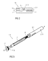
- FIG. 5 is a perspective view of an exemplary embodiment of a needle sheath removal mechanism 13 of an autoinjector 1 according to the present invention.
- the needle sheath removal mechanism 13 comprises an opening 11.1 axially arranged in the cap 11.
- the opening 11.1 is approximately sized and shaped to receive the protective needle sheath 5.
- One or more bosses 11.2 may be disposed on a proximal end of the cap 11 and adapted to abut the protective needle sheath 5. For example, when the protective needle sheath 5 is inserted into the opening 11.1, the protective needle sheath 5 may deform around the bosses 11.2.
- the bosses 11.2 may be ramped to reduce force necessary to insert the protective needle sheath 5 into the opening 11.1.
- the bosses 11.2 may abut a proximal end of the protective needle sheath 5 to prevent translation of the protective needle sheath 5 in the proximal direction P relative to the cap 11.
- the bosses 11.2 on the cap 11 may abut the proximal end of the protective needle sheath 5 and push the protective needle sheath 5 in the distal direction D off of the needle 4. with their non-ramped distal face.
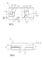
- Figure 6 is a schematic view of an exemplary embodiment of a plunger release mechanism 12 of the autoinjector 1 according to the present invention during assembly.
- the plunger release mechanism 12 is arranged for preventing release of the plunger 10 prior to retraction of the needle shroud 7 relative to the case 2 and for releasing the plunger 10 once the needle shroud 7 is sufficiently retracted.
- the plunger release mechanism 12 comprises the plunger 10, the rear case 2.2, and the needle shroud 7 interacting with each other.
- the needle shroud 7 is limited to axial movement relative to the case 2, and the plunger 10 can translate axially and rotate relative to the case 2.
- the plunger 10 comprises a first plunger boss 10.1 adapted to engage a shroud rib 7.7 on the needle shroud 7, a second plunger boss 10.2 adapted to engage a case slot 2.3 in the case 2, and a plunger rib 10.3 adapted to engage the shroud rib 7.7 on the needle shroud 7.
- the shroud rib 7.7 comprises a proximal face 7.8 adapted to engage the plunger rib 10.3, and a distal face 7.9 and a longitudinal face 7.10 adapted to engage the first plunger boss 10.1.
- the case slot 2.3 comprises a first angled surface 2.9 adapted to apply a rotational force in a first rotational direction R1 to the second plunger boss 10.2, a wall 2.10 adapted to abut the second plunger boss 10.2 to limit rotation of the plunger 10 relative to the case 2 in the first rotational direction R1, and a second angled surface 2.11 adapted to apply a rotational force in a second rotational direction R2, opposite the first rotational direction R1, to the second plunger boss 10.2.
- the plunger 10 with the drive spring 9 is inserted into the rear case 2.2.
- the plunger 10 is rotated in the first rotational direction R1 until the second plunger boss 10.2 is moved into the case slot 2.3 until it abuts the wall 2.10.
- the first angled surface 2.9 prevents the second plunger boss 10.2 from moving in the second rotational direction R2, and thus prevents the plunger 10 from rotating relative to the case 2.
- a pair of resilient beams 2.13 (shown in Figure 1 B) on the rear case 2.2 is adapted to snap into recesses 2.14 (shown in Figure 3 ) in the front case 2.1 to lock the drive subassembly 1.2 to the control subassembly 1.1.
- the needle shroud 7 translates proximally (e.g., by use of an assembly jig) causing the shroud rib 7.7 to abut the plunger rib 10.3.
- the angle of the plunger rib 10.3 causes the plunger 10 to rotate relative to the case 2 in the second rotational direction R2, and the second plunger boss 10.2 rides along the first angled surface 2.9 onto the second angled surface 2.11.
- the force of the drive spring 9 imparts a rotational force on the plunger 10 in the second rotational direction R2 due to the angle of the second angled surface 2.11.
- the needle shroud 7 when the needle shroud 7 is released (e.g., by removing the assembly jig), the needle shroud 7 translates in the distal direction D relative to the case 2 under the force the shroud spring 8 until the shroud rib 7.7 abuts the first plunger boss 10.1.
- the distal face 7.9 of the shroud rib 7.7 may abut the first plunger boss 10.1 and maintain the needle shroud 7 in an axial position relative to the case 2.
- the second plunger boss 10.2 is prevented from disengaging the case slot 2.3, because the shroud rib 7.7 prevents the plunger 10 from rotating in the second rotational direction R2 relative to the case 2.
- the longitudinal face 7.10 of the shroud rib 7.7 abuts the first plunger boss 10.1 to prevent rotation of the plunger 10.
- Figure 9 shows an exemplary embodiment of the first shroud lock mechanism 14 for an autoinjector 1 according to the present invention after assembly of the control subassembly 1.1.
- the compliant beam 11.3 on the cap is engaged in the aperture 7.6 within the needle shroud 7.
- the radial stop 2.15 is axially spaced from the compliant beam 11.3.
- Figure 10 shows an exemplary embodiment of the first shroud lock mechanism 14 for an autoinjector 1 according to the present invention during insertion of the syringe 3 into the control subassembly 1.1 for engaging the protective needle sheath 5 to the cap 11.
- the aperture 7.6 provides some clearance allowing a movement of the needle shroud 7 relative to the cap 11 in the distal direction D.
- the front case 2.1 is also moved in the distal direction D relative to the cap 11 axially aligning the radial stop 2.15 with the compliant beam 11.3 preventing the cap 11 from disengaging the needle shroud 7.
- Figure 11 shows an exemplary embodiment of the first shroud lock mechanism 14 for an autoinjector 1 according to the present invention, wherein after insertion of the syringe 3, the needle shroud 7 is moved further in the proximal direction P relative to the front case 2.1 by an assembly jig (not illustrated).
- the drive subassembly 1.2 may be assembled to the control subassembly 1.1.
- the compliant beam 11.3 remains engaged in the aperture 7.6 and the radial stop 2.15 prevents them from disengaging.
- the assembly jig is removed allowing the needle shroud 7 to move back in the distal direction D relative to the front case 2.1 under the force of the shroud spring 8 arriving again in the state illustrated in figure 10 .
- the needle shroud 7 is prevented from moving in the proximal direction P relative to the case 2, because the radial stop 2.15 prevents the compliant beam 11.3 from disengaging the aperture 7.6 and the rib 11.4 on the cap 11 proximally abuts the front case 2.1.
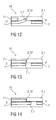
- Figure 12 shows an exemplary embodiment of the second shroud lock mechanism 15 for an autoinjector 1 according to the present invention after assembly of the control subassembly 1.1.
- the needle shroud 7 is partially inserted into the cap 11.
- the shroud beam 7.1 is in a non-deflected position proximally abutting the stop 2.12 in the front case 2.1. This prevents the needle shroud 7 from moving further in the proximal direction P relative to the front case 2.1 and keeps the control subassembly 1.1 locked together.
- Figure 13 shows an exemplary embodiment of the second shroud lock mechanism 15 for an autoinjector 1 according to the present invention during insertion of the syringe 3 into the control subassembly 1.1, wherein the needle shroud 7 is moved further in the distal direction D into the cap 11 such that the cap 11 radially inwardly deflects the shroud beam 7.1 out of its abutment with the stop 2.12.
- the needle shroud 7 is thus free to move in the proximal direction P relative to the front case 2.1.
- Figure 14 shows an exemplary embodiment of the second shroud lock mechanism 15 for an autoinjector 1 according to the present invention after final assembly of the drive subassembly 1.2 to the control subassembly 1.1.
- the needle shroud 7 has been moved further in the proximal direction P relative the front case 2.1 by an assembly jig (not illustrated).
- the drive subassembly 1.2 may be assembled to the control subassembly 1.1.
- the assembly jig is removed and the needle shroud 7 translates in the distal direction D relative to the front case 2.1 under the force of the shroud spring 8 until the shroud rib 7.7 abuts the first plunger boss 10.1.
- the shroud beam 7.1 is prevented from deflecting radially outward by the stop 2.12 in the front case 2.1.
- Figure 15A is a longitudinal section of an exemplary embodiment of an autoinjector 1 according to the present invention after final assembly
- Figure 15B is a schematic side view of an exemplary embodiment of an autoinjector 1 according to the present invention after final assembly, wherein the case 2 is removed for clarity.
- the autoinjector 1 may be kept in temperature controlled environment (e.g., cold chain storage) to, for example, reduce creep in highly stressed components, e.g. under load from the drive spring 9.
- temperature controlled environment e.g., cold chain storage
- the autoinjector 1 is removed from the packaging.
- the medicament in the syringe 3 may be visually inspected through a viewing window (not shown), which can be a transparent part of the case 2 or a cut-out in the case 2 aligned with the syringe 3.
- the cap 11 is removed by pulling it in the distal direction D away from the case 2.
- the bosses 11.2 on the cap 11 frictionally engage the protective needle sheath 5 and pull it off the needle 4 as the cap 11 is pulled in the distal direction D, and the compliant beam 11.3 disengages the aperture 7.6 in the needle shroud 7, as shown in Figure 16 .
- the compliant beam 11.3 translates distally within the aperture 7.6 until it is no longer abutted radially by the radial stop 2.15 and engages a proximal surface of the aperture 7.6 (which may be ramped) and deflects radially to disengage the aperture 7.6.
- the syringe 3 is fixed in position relative to the case 2, so pulling the cap 11 in the distal direction D does not cause any axial movement of the syringe 3.
- the syringe 3 is also fixedly rotationally relative to the case 2 (e.g., by an interference fit with the case 2 and/or the needle shroud 7).
- Figure 17A is a longitudinal section of an exemplary embodiment of the autoinjector 1 according to the present invention prior to use.
- Figure 17B is a schematic side view of an exemplary embodiment of the autoinjector 1 according to the present invention prior to use, wherein the case 2 is removed for clarity.
- the needle shroud 7 When the cap 11 is removed, the needle shroud 7 is in a first extended position FEP relative to the case 2, protruding from the case 2 in the distal direction D.
- the first extended position FEP is defined by the first plunger boss 10.1 abutting the shroud rib 7.7.
- Figure 18A is a longitudinal section of an exemplary embodiment of the autoinjector 1 according to the present invention during use.
- Figure 18B is a schematic side view of an exemplary embodiment of the autoinjector 1 according to the present invention during use, wherein the case 2 is removed for clarity.
- the needle shroud 7 When the autoinjector 1 is pressed against an injection site, the needle shroud 7 translates proximally relative to the case 2 against the biasing force of the shroud spring 8 from the first extended position FEP to a retracted position RP, as shown in Figures 18A and 18B .
- Figure 19 shows an exemplary embodiment of the plunger release mechanism 12 when the needle shroud 7 is in the retracted position RP.
- the needle shroud 7 translates distally causing the first plunger boss 10.1 to, starting from the position shown in figure 8 , ride along the shroud rib 7.7 until it is distal of the shroud rib 7.7.
- the plunger 10 is no longer prevented from rotating in the second rotational direction R2 relative to the case 2.
- the needle shroud 7 may include an aperture, a recess or a slot proximal of the shroud rib 7.7 to accommodate the first plunger boss 10.1 when the needle shroud 7 is in the retracted position RP and the plunger 10 rotates relative to the case 2.
- the shroud rib 7.7 may include a resistance feature (e.g., a projection, a ramp, a recess, etc.) adapted to abut the first plunger boss 10.1 as the needle shroud 7 translates from the first extended position FEP to the retracted position RP.
- a resistance feature e.g., a projection, a ramp, a recess, etc.
- a tactile feedback is provided in the form of increased resistance to pressing the autoinjector 1 against the injection site. The tactile feedback may be used to indicate that needle 4 will be inserted into the injection site upon further depression of the autoinjector 1 against the injection site.
- the needle shroud and reposition as the needle shroud 7 will re-extend to its initial position under the force of the shroud spring 8.
- the needle shroud 7 is in the retracted position RP, the needle 4 has been inserted into the injection site.
- a penetration depth of the needle 4 may be varied by, for example, limiting retraction of the needle shroud 7 relative to the case 2, modifying an axial position of the syringe 3 relative to the case 2, modifying a length of the needle 4, etc.
- the autoinjector 1 of the present invention may be used for subcutaneous, intra-dermal and/or intra-muscular injection.
- Figure 20A is a longitudinal section of an exemplary embodiment of the autoinjector 1 according to the present invention during use.
- Figure 20B is a schematic side view of an exemplary embodiment of the autoinjector 1 according to the present invention during use, wherein the case 2 is removed for clarity.
- the plunger 10 When the plunger 10 has rotated a sufficient distance in the second rotational direction R2 such that the second plunger boss 10.2 disengages the case slot 2.3, the plunger 10 is free to translate axially, under the force of the drive spring 9, relative to the case 2 to push the stopper 6 to deliver the medicament M from the syringe 3 through the needle 4.
- disengagement of the first plunger boss 10.1 from the shroud rib 7.7 and/or the second plunger boss 10.2 from the case slot 2.3 may provide an audible feedback indicating that delivery of the medicament M has started.
- a viewing window in the case 2 may allow for a visual feedback that the plunger 10 is advancing within the syringe 3 for assessing the progress of displacement of the medicament M.
- Figure 21A is a longitudinal section of an exemplary embodiment of the autoinjector 1 according to the present invention after use.
- Figure 21B is a schematic side view of an exemplary embodiment of the autoinjector 1 according to the present invention after use, wherein the case 2 is removed for clarity.
- the needle shroud 7 When the autoinjector 1 is removed from the injection site, the needle shroud 7 translates distally relative to the case 2 from the retracted position RP to a second extended position SEP under the biasing force of the shroud spring 8.
- the needle shroud 7 In the second extended position SEP, the needle shroud 7 extends beyond a distal tip of the needle 4 and locks in an axial position relative to the case 2.
- the second extended position SEP prevents needle-stick injury and may also indicate that the autoinjector 1 has been used (because the needle shroud 7 cannot move proximally from the second extended position SEP).
- the needle shroud 7 protrudes further, e.g. 2 mm, from the case 2 than in the first extended position FEP.
- the needle shroud 7 may include an indicia (e.g., a red ring, text, a graphic) on a portion which is visually accessible when the needle shroud 7 is in the second extended position SEP but not in the first extended position FEP.
- the indicia may indicate that the autoinjector 1 has been used.
- FIG 22 is a schematic view of an exemplary embodiment of the second shroud lock mechanism 15 according to the present invention.
- the shroud beam 7.1 passes the stop 2.12 in the distal direction D and relaxes radially outwards which is possible as the cap 11 is no longer present.
- the needle shroud 7 cannot translate proximally relative to the case 2, because the shroud beam 7.1 abuts the stop 2.12. The needle shroud 7 is thus locked in the second extended position SEP.
- Extension of the needle shroud 7 distally beyond the second extended position SEP may be prevented by a shroud boss 7.2 on the needle shroud 7 that abuts a case boss 2.8 on the case 2 (see Figure 1 ).
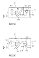
- Figures 23A to 23 E are schematic views of another exemplary embodiment of a plunger release mechanism 12 of the autoinjector 1 according to the present invention.
- the plunger release mechanism 12 is arranged for preventing release of the plunger 10 prior to retraction of the needle shroud 7 relative to the case 2 and for releasing the plunger 10 once the needle shroud 7 is sufficiently retracted.
- the plunger release mechanism 12 comprises the plunger 10, the rear case 2.2, and the needle shroud 7 interacting with each other.
- the needle shroud 7 is limited to axial movement relative to the case 2, and the plunger 10 can translate axially and rotate relative to the case 2.
- the plunger 10 comprises a first plunger boss 10.1 adapted to engage a shroud rib 7.7 on the needle shroud 7 and a second plunger boss 10.2 adapted to engage a case slot 2.3 in the case 2, and a plunger rib 10.3 adapted to engage the shroud rib 7.7 on the needle shroud 7.
- the shroud rib 7.7 comprises a proximal face 7.8 adapted to engage the plunger rib 10.3, and a distal face 7.9 adapted to engage the first plunger boss 10.1.
- the case slot 2.3 comprises a first angled surface 2.9 adapted to apply a rotational force in a first rotational direction R1 to the second plunger boss 10.2, a wall 2.10 adapted to abut the second plunger boss 10.2 to limit rotation of the plunger 10 relative to the case 2 in the first rotational direction R1, and a transversal surface 2.16.
- Figure 23A is a schematic view of an exemplary embodiment of the plunger release mechanism 12 of the autoinjector 1 according to the present invention during assembly of the drive subassembly 1.2.
- the plunger 10 with the drive spring 9 is inserted into the rear case 2.2.
- the plunger 10 is rotated in the first rotational direction R1 until the second plunger boss 10.2 is moved into the case slot 2.3 until it abuts the wall 2.10.
- the first angled surface 2.9 prevents the second plunger boss 10.2 from moving in the second rotational direction R2, and thus prevents the plunger 10 from rotating relative to the case 2.
- a pair of resilient beams 2.13 (shown in Figure 1 B) on the rear case 2.2 is adapted to snap into recesses 2.14 (shown in Figure 3 ) in the front case 2.1 to lock the drive subassembly 1.2 to the control subassembly 1.1.
- Figure 23B shows the drive assembly 1.2 being coupled to the control subassembly 1.1, wherein the needle shroud 7 translates proximally (e.g., by use of an assembly jig) causing the shroud rib 7.7 to abut the plunger rib 10.3.
- the angle of the plunger rib 10.3 causes the plunger 10 to rotate relative to the case 2 in the second rotational direction R2, and the second plunger boss 10.2 rides along the first angled surface 2.9 onto the transversal surface 2.16.
- the needle shroud 7 when the needle shroud 7 is released (e.g., by removing the assembly jig), the needle shroud 7 translates in the distal direction D relative to the case 2 under the force of the shroud spring 8 until the shroud rib 7.7 abuts the first plunger boss 10.1.
- the distal face 7.9 of the shroud rib 7.7 may abut the first plunger boss 10.1 and maintain the needle shroud 7 in an axial position relative to the case 2.
- the second plunger boss 10.2 is prevented from disengaging the case slot 2.3 as it abuts the transversal surface 2.16 in the distal direction D.
- Figure 23E shows an exemplary embodiment of the plunger release mechanism 12 when the needle shroud 7 is in the retracted position RP.
- the needle shroud 7 translates distally causing the shroud rib 7.7 to, starting from the position shown in figure 23D , ride along the plunger rib 10.3 thereby rotating the second plunger boss 10.2 in the second rotational direction R2 along the transversal surface 2.16 until the second plunger boss 10.2 disengages the case slot 2.3 thus releasing the plunger 10.
- the plunger 10 translates axially relative to the case 2 to deliver the medicament M from the syringe 3.
- a tactile feedback may be provided in the form of an increase in resistance when the needle shroud 7 abuts and pushes against the plunger rib 10.3.
- the tactile feedback may indicate that needle insertion is or will commence, or medicament delivery will be initiated, if the autoinjector 1 is pressed further against the injection site.
- transversal surface 2.16 could be replaced by or comprise a concave shape for preventing inadvertent release of the plunger 10.
- the plunger 10 may not have the first plunger boss 10.1, the plunger rib 10.3 may be disposed at different angle than as described above, and the case slot 2.3 may not be angled relative to a transverse axis of the case 2.
- the plunger 10 when the autoinjector 1 is assembled, the plunger 10 is maintained in axial position relative to the case 2, because the second plunger boss 10.2 engages the case slot 2.3.
- case slot 2.3 may not impart any rotational force on the second plunger boss 10.2 (or, in another exemplary embodiment, the case slot 2.3 may be angled to impart a rotational force on the second plunger boss 10.2 in the first rotational direction R1 to ensure that the second plunger boss 10.2 does not disengage the case slot 2.3 inadvertently).
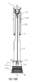
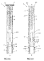
- Figures 24A and 24B show different longitudinal sections of another exemplary embodiment of the autoinjector 1.
- the syringe, the needle and the protective needle sheath are not shown for clarity.
- the illustrated embodiment may be arranged basically corresponding to the preciously described embodiments. The following description therefore predominantly deals with the differences of the embodiment of figures 24A and 24B to the previous ones.
- a cap 11 may be removably disposed at a distal end of the case 2.
- the cap 11 may include an element (e.g., a barb, a hook, a narrowed section, etc.) arranged to engage the protective needle sheath, the case 2 and/or a needle shroud 7 telescoped within the case 2.
- the illustrated cap 11 does not comprise grip features.
- the cap 11 of figures 24A and 24B may likewise comprise the grip features of the previously described embodiments for facilitating removal of the cap 11 (e.g., by twisting and/or pulling the cap relative to the case 2).
- a plunger release mechanism may be arranged for preventing release of the plunger 10 prior to retraction of the needle shroud 7 relative to the case 2 and for releasing the plunger 10 once the needle shroud 7 is sufficiently retracted.
- the plunger release mechanism is not shown in figures 24A and 24B for clarity. However, a plunger release mechanism 12 such as the ones illustrated in the previous figures may be applied in the embodiment of figures 24A and 24B .
- a first shroud lock mechanism 14 is arranged to prevent retraction of the needle shroud 7 relative to the case 2 when the cap 11 is in place, thereby avoiding unintentional activation of the autoinjector 1 (e.g., if dropped, during shipping or packaging, etc.).
- the first shroud lock mechanism 14 may comprise one or more compliant beams 11.3 on the cap 11 and a respective number of apertures 7.6 in the needle shroud 7 adapted to receive each of the compliant beams 11.3.
- the compliant beams 11.3 abut a radial stop 2.15 on the case 2 which prevents the compliant beams 11.3 from disengaging the apertures 7.6.
- the apertures 7.6 do not permit a limited axial movement of the cap 11 relative to the shroud 7.
- the cap 11 is attached to the autoinjector 1
- axial movement of the cap 11 in the proximal direction P relative the case 2 is limited by the cap 11 abutting the case 2.
- the compliant beams 11.3 may abut an edge of the aperture 7.6 and deflect to disengage the aperture 7.6, allowing for removal of the cap 11 and the protective needle sheath attached thereto.
- the compliant beams 11.3 and/or the apertures 7.6 may be ramped to reduce force necessary to disengage the compliant beams 11.3 from the apertures 7.6.
- the cap furthermore comprises at least one compliant case beam 11.6 adapted to engage in a respective number of apertures 2.16 in the case 2.
- the compliant case beams 11.6 may abut an edge of the aperture 2.16 and deflect to disengage the aperture 2.16, allowing for removal of the cap 11 and the protective needle sheath attached thereto.
- the compliant case beams 11.6 and/or the apertures 2.16 may be ramped to reduce force necessary to disengage the compliant case beams 11.6 from the apertures 2.16.
- a second shroud lock mechanism 15 is adapted to lock the needle shroud 7 in an axial position relative to the case 2 after the autoinjector 1 has been removed from the injection site.
- the second shroud lock mechanism 15 comprises at least one compliant shroud beam 7.1 on the needle shroud 7 adapted to proximally abut a stop 2.12 on the case 2 after the autoinjector 1 has been removed from the injection site.
- the abutment of the shroud beam 7.1 on the stop 2.12 prevents translation of the needle shroud 7 in the proximal direction P relative to the case 2.
- the stop 2.12 may be arranged on a compliant beam 2.17 in the case2 to facilitate the initial assembly of the shroud 7.
- the shroud 7 can be assembled without the syringe 3 present so that the beam 2.17 with the stop 2.12 can deflect radially in and allows the shroud beam 7.1 to pass.
- the syringe 3 is then inserted and subsequently inwardly supports the beam 2.17 preventing it from deflecting radially inward thus creating an immovable stop 2.12. This allows for dispensing with the function of the cap illustrated in figures 12 to 14 .
- the autoinjector 1 may be formed from at least two subassemblies, e.g., a control subassembly 1.1 and a drive subassembly 1.2 such as the one shown in figure 4 and described in the corresponding section above to allow for flexibility as to the time and location of manufacture of the subassemblies 1.1, 1.2 and final assembly with the syringe 3.
- a control subassembly 1.1 and a drive subassembly 1.2
- a drive subassembly 1.2 such as the one shown in figure 4 and described in the corresponding section above to allow for flexibility as to the time and location of manufacture of the subassemblies 1.1, 1.2 and final assembly with the syringe 3.
- the control subassembly 1.1 comprises the cap 11, the needle shroud 7, the shroud spring 8 and the front case 2.1.
- the shroud spring 8 is inserted into the needle shroud 7, and the needle shroud 7 with the shroud spring 8 is inserted into the front case 2.1.
- the cap 11 is arranged over the distal end of the needle shroud 7 and engages both the needle shroud 7 and the case 2 by the compliant beams 11.3, 11.6 being engaged in the apertures 7.6, 2.16.
- the shroud spring 8 is thus in an at least slightly loaded state wherein the load is statically resolved between the case 2 and the shroud 7 which are coupled through the compliant beams 11.3, 11.6 on the cap 11.
- the force exerted by the shroud spring 8 in that state is in a range from 2 N to 10 N whereas a force required to remove the cap 11 is greater, e.g. up to 25 N due to the design of the compliant case beams 11.6.
- the compliant case beam 11.6 is thus designed to safely resolve the force from the shroud spring 8 and yet allow easy removal of the cap 11.
- the drive subassembly 1.2 is coupled to the control subassembly 1.1.
- a pair of resilient beams (not illustrated but similar to the ones shown in Figure 1 B) on the rear case 2.2 is adapted to snap into recesses (not illustrated) in the front case 2.1 to lock the drive subassembly 1.2 to the control subassembly 1.1.
- the needle shroud 7 does not have to be translated proximally by use of an assembly jig as in the previously described embodiments.
- the shroud 7 is already in the correct position and the control spring 8 is in the at least slightly loaded state.
- Coupling the drive assembly 1.2 to the control subassembly 1.1 thus causes the shroud rib 7.7 to abut the plunger rib 10.3.
- the angle of the plunger rib 10.3 causes the plunger 10 to rotate relative to the case 2 in the second rotational direction R2, and the second plunger boss 10.2 rides along the first angled surface 2.9 onto the second angled surface 2.11.
- the force of the drive spring 9 imparts a rotational force on the plunger 10 in the second rotational direction R2 due to the angle of the second angled surface 2.11.
- the autoinjector 1 may be kept in temperature controlled environment (e.g., cold chain storage) to, for example, reduce creep in highly stressed components, e.g. under load from the drive spring 9 and shroud spring 8.
- temperature controlled environment e.g., cold chain storage
- the needle shroud 7 when the needle shroud 7 is released (e.g., by a user pulling the cap 11 in the distal direction D thereby disengaging the compliant case beams 11.6 from the respective apertures 2.16 in the case 2 while the first compliant beams 11.3 remain engaged in the apertures 7.6 within the shroud 7), the needle shroud 7 translates in the distal direction D relative to the case 2 under the force of the shroud spring 8 until the shroud rib 7.7 abuts the first plunger boss 10.1.
- the distal face 7.9 of the shroud rib 7.7 may abut the first plunger boss 10.1 and maintain the needle shroud 7 in an axial position relative to the case 2.
- the second plunger boss 10.2 is prevented from disengaging the case slot 2.3, because the shroud rib 7.7 prevents the plunger 10 from rotating in the second rotational direction R2 relative to the case 2.
- the longitudinal face 7.10 of the shroud rib 7.7 abuts the first plunger boss 10.1 to prevent rotation of the plunger 10.
- movement of the needle shroud 7 in the proximal direction P relative to the case 2 is restricted, because the radial stop 2.15 prevents the compliant beam 11.3 from disengaging the aperture 7.6 and the rib 11.4 on the cap 11 proximally abuts the front case 2.1.
- the axial position of the shroud 7 defined by the distal face 7.9 and the first plunger boss 10.1 may be such that the shroud beam 7.1 does not travel distally beyond the stop 2.12 in the front case 2.1 in that state.
- a further sequence of operation of the embodiment of the autoinjector 1 illustrated in figures 24A and 24B may be corresponding to the sequence of operation described above for the embodiments shown in the previous figures.
- a tamper strip (not shown) may be arranged between the cap 11 and the front case 2.1 when the control subassembly 1.1 is assembled.
- the tamper strip may be useful for quality assurance.
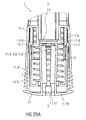
- Figure 25A is a schematic view of a distal end of an exemplary embodiment of an autoinjector 1 according to the present invention during assembly.
- the autoinjector 1 comprises a case 2 adapted to hold a medicament container, such as a syringe.
- a cap 11 may be removably disposed at a distal end of the case 2.
- the cap 11 may include an element (e.g., a barb, a hook, a narrowed section, etc.) arranged to engage the case 2, a needle shroud 7 telescoped within the case, and/or a protective needle sheath on the needle.
- the protective needle sheath may be rubber and/or plastic.
- the protective needle sheath is a rigid needle shield (RNS) formed from a rubber interior adapted to engage the needle with a plastic exterior at least partially covering an outer portion of the rubber interior.
- the cap 11 may comprise grip features 11.5 for facilitating removal of the cap 11 (e.g., by twisting and/or pulling the cap 11 relative to the case 2).
- the grip features 11.5 may include one or more ribs, ridges, projections, bumps, notches, textured surfaces, or an overmolded coating (rubber, elastic, etc.), etc.
- a shroud spring 8 is arranged to bias the needle shroud 7 distally toward an extended position relative to the case 2.
- the device 1 is pressed against an injection site causing the needle shroud 7 to move proximally relative to the case 2 to a retracted position against the biasing force of the shroud spring 8.
- a sheath removal mechanism 13 is arranged to remove the protective needle sheath from the medicament container on removal of the cap 11 from the autoinjector 1.
- the sheath removal mechanism 13 may comprise one or more compliant sheath removal beams 11.7 on the cap 11 adapted to engage the protective needle sheath.
- the sheath removal beams 11.7 extend in a proximal direction P from a distal face 11.10 of the cap 11 or are part of an internal sleeve extending in the proximal direction P from a distal face 11.10 of the cap 11.
- the compliant sheath removal beams 11.7 comprise respective inward ledges 11.8.
- FIG. 25B is a schematic view of an exemplary embodiment of the cap 11.
- the opening 11.11 is shaped similar to a keyhole such that an assembly tool may be inserted off centre and engage between at least two of the sheath removal beams 11.7 without blocking the path for a protective needle sheath during insertion.
- one or more lateral apertures 11.9 are arranged in a lateral area of the cap 11 to allow insertion of an assembling tool.
- Corresponding lateral apertures 2.6, 7.3 may likewise be arranged in the case 2 and the needle shroud 7 in such a manner that a set of lateral apertures 11.9, 2.6, 7.3 respectively aligns when the cap 11 is attached to the case 2.
- the cap 11 is assembled to the autoinjector 1 by being moved in a proximal direction P relative to the needle shroud 7.
- the sheath removal beams 11.7 are inserted into the needle shroud 7 which is sufficiently wide to allow this.
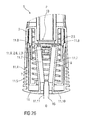
- Figure 26 is a schematic view of the distal end of the autoinjector 1 with the assembled cap 11 during insertion of a wedge shaped assembly tool 16 through the opening 11.11 in the distal face 11.10.
- the wedge shaped assembly tool 16 engages between two of the sheath removal beams 11.7 splaying them apart thereby deflecting them in a radial outward direction. This opens up the clearance defined by the inward ledges 11.8 to an extent allowing a protective needle sheath to pass through.
- the wedge shaped assembly tool 16 can also be arranged to displace the shroud 7 axially in the same motion enabling the engagement of the second shroud lock mechanism 15 and priming of the plunger release mechanism 12.
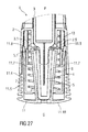
- Figure 27 is a schematic view of the distal end of the autoinjector 1 with the assembled cap 11 during assembly of a medicament container 3 with a protective needle sheath 5.
- the medicament container 3 may be a pre-filled medicament container and have a needle 4 arranged at a distal end.
- a protective needle sheath 5 may be removably coupled to the needle 4.
- the protective needle sheath 5 may be a rubber needle sheath or a rigid needle sheath (which is composed of rubber and a full or partial plastic shell).
- the medicament container may be a cartridge which includes the medicament M and engages a removable needle (e.g., by threads, snaps, friction, etc.).
- the case 2 may comprise an axial stop 2.5 limiting axial movement of the medicament container 3 within the case 2 in the distal direction D, e.g. by engaging a neck portion 3.1 of the medicament container 3.
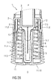
- Figure 28 is a schematic view of the distal end of the autoinjector 1 with the assembled cap 11, medicament container 3 and protective needle sheath 5.
- the assembly tool 16 is removed from the opening 11.11 in the distal face 11.10 of the cap 11 such that the sheath removal beams 11.7 are no longer splayed apart. Due to their beam stiffness the sheath removal beams 11.7 relax radially inwards, the inward ledges 11.8 reduce the clearance between them and engage a proximal end 5.1 of the protective needle sheath 5 thus axially coupling the cap 11 to the protective needle sheath 5.
- the sheath removal beams 11.7 are moulded in an inward deflected position which ensures they are always in intimate contact with the protective needle sheath 5 once the tool is removed.
- the wedge shaped assembly tool 16 is designed so that the sheath removal beams 11.7 are not deformed so far as to plastically yield.
- the contact point between the protective needle sheath 5 and the sheath removal beams 11.7 is arranged to minimise the moment acting to open the sheath removal beams 11.7 as the protective needle sheath 5 is removed.
- gripping of the protective needle sheath 5 does not rely on radial compressive force exerted by the sheath removal beams 11.7 but on a force exerted to the cap 11 in the distal direction D relative to the case 2.
- the wedge shaped assembly tool 16 may be arranged to splay the sheath removal beams 11.7 in a direction perpendicular to the direction of the forece exerted to the cap 11 during cap removal.
- a force required to press the needle shroud 7 may be approximately 2-12 N.
- the mechanism may work with a higher force.
- the syringe 3 used in the autoinjector 1 may be a syringe capable of containing approximately 1 mL of the medicament M. In another exemplary embodiment, the syringe 3 used in the autoinjector 1 may be a syringe capable of containing approximately 2mL of the medicament M.
- the autoinjector 1 according to the present invention may have an increased shelf-life compared to conventional autoinjectors, because, for example, only the plunger 10 is subjected to the relatively high force of the drive spring 9.
- the autoinjector 1 according to the present invention may be used as a platform as the drive spring 9 can be changed to alter a force applied to the plunger 10, e.g., for delivering medicaments with different viscosities drugs or reconstituted medicaments, or changing a time required to inject a dose of the medicament.
- the cap 11 is suitable for being applied with any kind of injection device or autoinjector.
- drug or “medicament”, as used herein, means a pharmaceutical formulation containing at least one pharmaceutically active compound, wherein in one embodiment the pharmaceutically active compound has a molecular weight up to 1500 Da and/or is a peptide, a proteine, a polysaccharide, a vaccine, a DNA, a RNA, an enzyme, an antibody or a fragment thereof, a hormone or an oligonucleotide, or a mixture of the above-mentioned pharmaceutically active compound, wherein in a further embodiment the pharmaceutically active compound is useful for the treatment and/or prophylaxis of diabetes mellitus or complications associated with diabetes mellitus such as diabetic retinopathy, thromboembolism disorders such as deep vein or pulmonary thromboembolism, acute coronary syndrome (ACS), angina, myocardial infarction, cancer, macular degeneration, inflammation, hay fever, atherosclerosis and/or rheumatoid arthritis, wherein in a further
- Insulin analogues are for example Gly(A21), Arg(B31), Arg(B32) human insulin; Lys(B3), Glu(B29) human insulin; Lys(B28), Pro(B29) human insulin; Asp(B28) human insulin; human insulin, wherein proline in position B28 is replaced by Asp, Lys, Leu, Val or Ala and wherein in position B29 Lys may be replaced by Pro; Ala(B26) human insulin; Des(B28-B30) human insulin; Des(B27) human insulin and Des(B30) human insulin.
- Insulin derivates are for example B29-N-myristoyl-des(B30) human insulin; B29-N-palmitoyl-des(B30) human insulin; B29-N-myristoyl human insulin; B29-N-palmitoyl human insulin; B28-N-myristoyl LysB28ProB29 human insulin; B28-N-palmitoyl-LysB28ProB29 human insulin; B30-N-myristoyl-ThrB29LysB30 human insulin; B30-N-palmitoyl- ThrB29LysB30 human insulin; B29-N-(N-palmitoyl-Y-glutamyl)-des(B30) human insulin; B29-N-(N-lithocholyl-Y-glutamyl)-des(B30) human insulin; B29-N-( ⁇ -carboxyheptadecanoyl)-des(B30) human insulin and B29-N-( ⁇ -carbox
- Exendin-4 for example means Exendin-4(1-39), a peptide of the sequence H-His-Gly-Glu-Gly-Thr-Phe-Thr-Ser-Asp-Leu-Ser-Lys-Gln-Met-Glu-Glu-Glu-Ala-Val-Arg-Leu-Phe-Ile-Glu-Trp-Leu-Lys-Asn-Gly-Gly-Pro-Ser-Ser-Gly-Ala-Pro-Pro-Pro-Ser-NH2.
- Exendin-4 derivatives are for example selected from the following list of compounds:
- Hormones are for example hypophysis hormones or hypothalamus hormones or regulatory active peptides and their antagonists as listed in Rote Liste, ed. 2008, Chapter 50, such as Gonadotropine (Follitropin, Lutropin, Choriongonadotropin, Menotropin), Somatropine (Somatropin), Desmopressin, Terlipressin, Gonadorelin, Triptorelin, Leuprorelin, Buserelin, Nafarelin, Goserelin.
- Gonadotropine Follitropin, Lutropin, Choriongonadotropin, Menotropin
- Somatropine Somatropin
- Desmopressin Terlipressin
- Gonadorelin Triptorelin
- Leuprorelin Buserelin
- Nafarelin Goserelin.
- a polysaccharide is for example a glucosaminoglycane, a hyaluronic acid, a heparin, a low molecular weight heparin or an ultra low molecular weight heparin or a derivative thereof, or a sulphated, e.g. a poly-sulphated form of the above-mentioned polysaccharides, and/or a pharmaceutically acceptable salt thereof.
- An example of a pharmaceutically acceptable salt of a poly-sulphated low molecular weight heparin is enoxaparin sodium.
- Antibodies are globular plasma proteins ( ⁇ 150 kDa) that are also known as immunoglobulins which share a basic structure. As they have sugar chains added to amino acid residues, they are glycoproteins.
- the basic functional unit of each antibody is an immunoglobulin (Ig) monomer (containing only one Ig unit); secreted antibodies can also be dimeric with two Ig units as with IgA, tetrameric with four Ig units like teleost fish IgM, or pentameric with five Ig units, like mammalian IgM.
- Ig immunoglobulin
- the Ig monomer is a "Y"-shaped molecule that consists of four polypeptide chains; two identical heavy chains and two identical light chains connected by disulfide bonds between cysteine residues. Each heavy chain is about 440 amino acids long; each light chain is about 220 amino acids long. Heavy and light chains each contain intrachain disulfide bonds which stabilize their folding. Each chain is composed of structural domains called Ig domains. These domains contain about 70-110 amino acids and are classified into different categories (for example, variable or V, and constant or C) according to their size and function. They have a characteristic immunoglobulin fold in which two ⁇ sheets create a "sandwich" shape, held together by interactions between conserved cysteines and other charged amino acids.
- Ig heavy chain There are five types of mammalian Ig heavy chain denoted by ⁇ , ⁇ , ⁇ , ⁇ , and ⁇ .
- the type of heavy chain present defines the isotype of antibody; these chains are found in IgA, IgD, IgE, IgG, and IgM antibodies, respectively.
- Distinct heavy chains differ in size and composition; ⁇ and ⁇ contain approximately 450 amino acids and ⁇ approximately 500 amino acids, while ⁇ and ⁇ have approximately 550 amino acids.
- Each heavy chain has two regions, the constant region (C H ) and the variable region (V H ).
- the constant region is essentially identical in all antibodies of the same isotype, but differs in antibodies of different isotypes.
- Heavy chains ⁇ , ⁇ and ⁇ have a constant region composed of three tandem Ig domains, and a hinge region for added flexibility; heavy chains ⁇ and ⁇ have a constant region composed of four immunoglobulin domains.
- the variable region of the heavy chain differs in antibodies produced by different B cells, but is the same for all antibodies produced by a single B cell or B cell clone.
- the variable region of each heavy chain is approximately 110 amino acids long and is composed of a single Ig domain.
- a light chain has two successive domains: one constant domain (CL) and one variable domain (VL).
- CL constant domain
- VL variable domain
- the approximate length of a light chain is 211 to 217 amino acids.
- Each antibody contains two light chains that are always identical; only one type of light chain, ⁇ or ⁇ , is present per antibody in mammals.
- variable (V) regions are responsible for binding to the antigen, i.e. for its antigen specificity.
- VL variable light
- VH variable heavy chain
- CDRs Complementarity Determining Regions
- an "antibody fragment” contains at least one antigen binding fragment as defined above, and exhibits essentially the same function and specificity as the complete antibody of which the fragment is derived from.
- Limited proteolytic digestion with papain cleaves the Ig prototype into three fragments. Two identical amino terminal fragments, each containing one entire L chain and about half an H chain, are the antigen binding fragments (Fab).
- the Fc contains carbohydrates, complement-binding, and FcR-binding sites.
- F(ab')2 is divalent for antigen binding.
- the disulfide bond of F(ab')2 may be cleaved in order to obtain Fab'.
- the variable regions of the heavy and light chains can be fused together to form a single chain variable fragment (scFv).
- Pharmaceutically acceptable salts are for example acid addition salts and basic salts.
- Acid addition salts are e.g. HCl or HBr salts.
- Basic salts are e.g. salts having a cation selected from alkali or alkaline, e.g. Na+, or K+, or Ca2+, or an ammonium ion N+(R1)(R2)(R3)(R4), wherein R1 to R4 independently of each other mean: hydrogen, an optionally substituted C1-C6-alkyl group, an optionally substituted C2-C6-alkenyl group, an optionally substituted C6-C10-aryl group, or an optionally substituted C6-C10-heteroaryl group.
- solvates are for example hydrates.
Landscapes
- Health & Medical Sciences (AREA)
- Vascular Medicine (AREA)
- Engineering & Computer Science (AREA)
- Anesthesiology (AREA)
- Biomedical Technology (AREA)
- Heart & Thoracic Surgery (AREA)
- Hematology (AREA)
- Life Sciences & Earth Sciences (AREA)
- Animal Behavior & Ethology (AREA)
- General Health & Medical Sciences (AREA)
- Public Health (AREA)
- Veterinary Medicine (AREA)
- Infusion, Injection, And Reservoir Apparatuses (AREA)
Priority Applications (15)
| Application Number | Priority Date | Filing Date | Title |
|---|---|---|---|
| EP14162454.4A EP2923714A1 (de) | 2014-03-28 | 2014-03-28 | Durch hautkontakt ausgelöste Autoinjektor |
| TW104109664A TW201600132A (zh) | 2014-03-28 | 2015-03-26 | 自動注射器 |
| CN201580015102.3A CN106102801B (zh) | 2014-03-28 | 2015-03-27 | 通过皮肤接触触发的自动注射器 |
| JP2016558296A JP2017508546A (ja) | 2014-03-28 | 2015-03-27 | 皮膚接触によってトリガされる自己注射器 |
| EP15712171.6A EP3122400B1 (de) | 2014-03-28 | 2015-03-27 | Durch hautkontakt ausgelöste autoinjektor |
| EP24150964.5A EP4374892A3 (de) | 2014-03-28 | 2015-03-27 | Autoinjektor |
| DK19181615.6T DK3574942T3 (da) | 2014-03-28 | 2015-03-27 | Autoinjektor |
| EP19181615.6A EP3574942B1 (de) | 2014-03-28 | 2015-03-27 | Autoinjektor |
| DK15712171T DK3122400T3 (da) | 2014-03-28 | 2015-03-27 | Autoinjektor, der udløses ved hudkontakt |
| US15/125,014 US10646654B2 (en) | 2014-03-28 | 2015-03-27 | Autoinjector triggered by skin contact |
| PCT/EP2015/056686 WO2015144870A1 (en) | 2014-03-28 | 2015-03-27 | Autoinjector triggered by skin contact |
| JP2020022941A JP2020073165A (ja) | 2014-03-28 | 2020-02-14 | 皮膚接触によってトリガされる自己注射器 |
| US16/859,143 US11660396B2 (en) | 2014-03-28 | 2020-04-27 | Autoinjector |
| US18/305,766 US12233244B2 (en) | 2014-03-28 | 2023-04-24 | Autoinjector |
| US19/038,534 US20250170333A1 (en) | 2014-03-28 | 2025-01-27 | Autoinjector |
Applications Claiming Priority (1)
| Application Number | Priority Date | Filing Date | Title |
|---|---|---|---|
| EP14162454.4A EP2923714A1 (de) | 2014-03-28 | 2014-03-28 | Durch hautkontakt ausgelöste Autoinjektor |
Publications (1)
| Publication Number | Publication Date |
|---|---|
| EP2923714A1 true EP2923714A1 (de) | 2015-09-30 |
Family
ID=50389339
Family Applications (4)
| Application Number | Title | Priority Date | Filing Date |
|---|---|---|---|
| EP14162454.4A Ceased EP2923714A1 (de) | 2014-03-28 | 2014-03-28 | Durch hautkontakt ausgelöste Autoinjektor |
| EP19181615.6A Active EP3574942B1 (de) | 2014-03-28 | 2015-03-27 | Autoinjektor |
| EP15712171.6A Active EP3122400B1 (de) | 2014-03-28 | 2015-03-27 | Durch hautkontakt ausgelöste autoinjektor |
| EP24150964.5A Pending EP4374892A3 (de) | 2014-03-28 | 2015-03-27 | Autoinjektor |
Family Applications After (3)
| Application Number | Title | Priority Date | Filing Date |
|---|---|---|---|
| EP19181615.6A Active EP3574942B1 (de) | 2014-03-28 | 2015-03-27 | Autoinjektor |
| EP15712171.6A Active EP3122400B1 (de) | 2014-03-28 | 2015-03-27 | Durch hautkontakt ausgelöste autoinjektor |
| EP24150964.5A Pending EP4374892A3 (de) | 2014-03-28 | 2015-03-27 | Autoinjektor |
Country Status (7)
| Country | Link |
|---|---|
| US (4) | US10646654B2 (de) |
| EP (4) | EP2923714A1 (de) |
| JP (2) | JP2017508546A (de) |
| CN (1) | CN106102801B (de) |
| DK (2) | DK3574942T3 (de) |
| TW (1) | TW201600132A (de) |
| WO (1) | WO2015144870A1 (de) |
Cited By (11)
| Publication number | Priority date | Publication date | Assignee | Title |
|---|---|---|---|---|
| WO2017207224A1 (en) * | 2016-06-03 | 2017-12-07 | Carebay Europe Ltd. | Medicament delivery device |
| GB2560524A (en) * | 2017-03-13 | 2018-09-19 | Univ Cape Town | An auto-injector |
| JP2018535041A (ja) * | 2015-11-27 | 2018-11-29 | サノフィ−アベンティス・ドイチュラント・ゲゼルシャフト・ミット・ベシュレンクテル・ハフツング | 薬剤注射デバイス |
| WO2019086576A1 (en) * | 2017-11-03 | 2019-05-09 | Sanofi | Drug delivery device with drive sub-assembly |
| WO2020002321A1 (en) | 2018-06-25 | 2020-01-02 | Sanofi | Medicament delivery device |
| CN111712288A (zh) * | 2018-02-16 | 2020-09-25 | 贝克顿迪金森法国公司 | 用于支承填充有药物组分的医疗容器的医疗注射装置 |
| US11097065B2 (en) | 2016-06-22 | 2021-08-24 | Antares Pharma, Inc. | Needle-shield remover |
| WO2021190779A1 (en) * | 2020-03-26 | 2021-09-30 | Shl Medical Ag | Locking mechanism for a medicament delivery device |
| WO2024094701A1 (en) * | 2022-10-31 | 2024-05-10 | Sanofi | Assembly for a drug delivery device |
| WO2024094698A1 (en) * | 2022-10-31 | 2024-05-10 | Sanofi | Front sub-assembly for a drug delivery device |
| WO2024146838A1 (en) * | 2023-01-04 | 2024-07-11 | Shl Medical Ag | Medicament delivery device |
Families Citing this family (60)
| Publication number | Priority date | Publication date | Assignee | Title |
|---|---|---|---|---|
| EP2399635A1 (de) | 2010-06-28 | 2011-12-28 | Sanofi-Aventis Deutschland GmbH | Automatischer Injektor |
| PT2854708T (pt) | 2012-06-04 | 2017-01-17 | Alcon Pharmaceuticals Ltd | Dispositivo de inserção de lentes oculares e método de libertação de uma lente ocular a partir de um cartucho |
| EP2823841A1 (de) | 2013-07-09 | 2015-01-14 | Sanofi-Aventis Deutschland GmbH | Autoinjektor |
| EP2923714A1 (de) | 2014-03-28 | 2015-09-30 | Sanofi-Aventis Deutschland GmbH | Durch hautkontakt ausgelöste Autoinjektor |
| WO2015154049A1 (en) | 2014-04-04 | 2015-10-08 | Altaviz, Llc | Intraocular lens inserter |
| CN106572904B (zh) | 2014-07-15 | 2019-06-18 | 爱尔康制药有限公司 | 具有温度补偿的眼内透镜插入器 |
| CN107249666B (zh) * | 2015-01-16 | 2020-10-23 | 贝克顿迪金森法国 | 用于预填充容器的药品储存和分配系统 |
| WO2016145206A1 (en) | 2015-03-10 | 2016-09-15 | Regeneron Pharmaceuticals, Inc. | Aseptic piercing system and method |
| US10172706B2 (en) | 2015-10-31 | 2019-01-08 | Novartis Ag | Intraocular lens inserter |
| KR102209807B1 (ko) * | 2015-12-08 | 2021-01-29 | 벡톤 디킨슨 프랑스 | 의료용 주입기용 반구형 부분을 구비한 캡 |
| US11260176B2 (en) | 2015-12-30 | 2022-03-01 | Novo Nordisk A/S | Autoinjector having needle shield triggering |
| JP2019516490A (ja) | 2016-05-18 | 2019-06-20 | サノフィ−アベンティス・ドイチュラント・ゲゼルシャフト・ミット・ベシュレンクテル・ハフツング | シースリムーバおよびその組み立て方法 |
| US10335553B2 (en) | 2016-06-13 | 2019-07-02 | Shl Medical Ag | Cap assembly for a medicament delivery device |
| CN109922850B (zh) * | 2016-11-09 | 2023-05-09 | 赛诺菲-安万特德国有限公司 | 注射器装置 |
| US11000367B2 (en) | 2017-01-13 | 2021-05-11 | Alcon Inc. | Intraocular lens injector |
| ES2919934T3 (es) | 2017-05-05 | 2022-07-29 | Regeneron Pharma | Autoinyector y procedimientos de uso relacionados |
| US11213631B2 (en) | 2017-06-13 | 2022-01-04 | Difinity Solutions Inc. | Protected needle assembly for a hypodermic needle |
| EP4585240A3 (de) | 2017-11-03 | 2025-09-10 | Sanofi | Arzneimittelabgabevorrichtung |
| CN111936183B (zh) * | 2017-11-21 | 2023-03-03 | 赛诺菲 | 用于药物递送装置的驱动子组件 |
| EP3492126A1 (de) | 2017-12-01 | 2019-06-05 | Sanofi | Injektorvorrichtung |
| GB2570319B (en) | 2018-01-19 | 2021-01-06 | Consort Medical Plc | A medicament delivery device |
| EP3524297A1 (de) * | 2018-02-12 | 2019-08-14 | Sanofi | Injektorvorrichtung |
| US11759570B2 (en) | 2019-02-25 | 2023-09-19 | Difinity Solutions Inc. | Medicament injector and interchangeable cartridges therefor |
| JP7266696B2 (ja) * | 2019-02-26 | 2023-04-28 | ベクトン ディキンソン フランス | 作動防止キャップ付き自動注射器 |
| AU2020227208B2 (en) * | 2019-02-26 | 2022-10-06 | Becton Dickinson France | Auto-injector with needle cover |
| US12569625B2 (en) | 2019-02-26 | 2026-03-10 | Becton Dickinson France | Rigid needle shield remover with drop test feature for autoinjector |
| KR102655825B1 (ko) | 2019-02-26 | 2024-04-08 | 벡톤 디킨슨 프랑스 | 청각적 표시기를 가진 자동-주사 장치 |
| US12558495B2 (en) | 2019-02-26 | 2026-02-24 | Becton Dickinson France | Auto-injector with cap |
| WO2020216918A1 (en) | 2019-04-26 | 2020-10-29 | Becton Dickinson France | Needle cover with undercut |
| JP2022549687A (ja) * | 2019-09-30 | 2022-11-28 | アムジエン・インコーポレーテツド | 薬物送達デバイス |
| CN110681004A (zh) * | 2019-11-15 | 2020-01-14 | 苏州嘉树医疗科技有限公司 | 一种自动注射器 |
| US12502481B2 (en) | 2020-02-25 | 2025-12-23 | Difinity Solutions Inc. | Medicament injector and interchangeable cartridges therefor |
| US12005244B2 (en) | 2020-03-27 | 2024-06-11 | Medivena Sp. Z O.O. | Needle-based device based on direct wing-based coupling of a needle shield to a barrel thereof and safety mechanism implemented therein |
| WO2021199034A1 (en) * | 2020-03-30 | 2021-10-07 | E3D A.C.A.L | Automatic injection device |
| CN111450356B (zh) * | 2020-05-15 | 2024-10-18 | 宁波睿爱产品设计有限公司 | 一种自动注射装置 |
| WO2022002584A1 (en) * | 2020-06-30 | 2022-01-06 | Shl Medical Ag | Medicament delivery device |
| US20230398310A1 (en) * | 2020-10-21 | 2023-12-14 | Shl Medical Ag | An assembly for a medicament delivery device |
| WO2022181448A1 (en) * | 2021-02-24 | 2022-09-01 | Terumo Kabushiki Kaisha | Medication administration device |
| EP4173656A1 (de) | 2021-10-27 | 2023-05-03 | medmix Switzerland AG | Nadelschutz, medikamentenabgabevorrichtung und verfahren zum herstellen |
| JP7636639B2 (ja) * | 2021-11-05 | 2025-02-26 | エスエイチエル・メディカル・アーゲー | 薬剤送達デバイスのためのサブアセンブリ |
| USD1007676S1 (en) | 2021-11-16 | 2023-12-12 | Regeneron Pharmaceuticals, Inc. | Wearable autoinjector |
| WO2024094699A1 (en) | 2022-10-31 | 2024-05-10 | Sanofi | Container holder and drug delivery device comprising the container holder |
| EP4611846A1 (de) | 2022-10-31 | 2025-09-10 | Sanofi | Kolben zum ausstossen eines arzneimittels, arzneimittelabgabevorrichtung, hintere unteranordnung und zugehörige verfahren |
| WO2024094705A1 (en) | 2022-10-31 | 2024-05-10 | Sanofi | Drug delivery device having a two-part user indicator |
| CN120129548A (zh) | 2022-10-31 | 2025-06-10 | 赛诺菲 | 用于药物递送装置的布置、药物递送装置和组装方法 |
| CN120500361A (zh) | 2022-10-31 | 2025-08-15 | 赛诺菲 | 具有反馈元件的药物递送装置以及用于向药物递送装置的用户提供关于剂量分配过程的反馈的方法 |
| EP4611848A1 (de) | 2022-10-31 | 2025-09-10 | Sanofi | Vorrichtungskörper für eine arzneimittelabgabevorrichtung, anordnung für eine arzneimittelabgabevorrichtung und arzneimittelabgabevorrichtung |
| EP4611849A1 (de) | 2022-10-31 | 2025-09-10 | Sanofi | Verfahren zur montage einer anordnung für eine arzneimittelabgabevorrichtung und arzneimittelabgabevorrichtung |
| WO2024094706A1 (en) | 2022-10-31 | 2024-05-10 | Sanofi | Audible indicator, indicator holder and method of assembling an audible indicator |
| EP4646249A1 (de) * | 2023-01-04 | 2025-11-12 | SHL Medical AG | Medikamentenabgabevorrichtung |
| EP4651922A1 (de) | 2023-01-17 | 2025-11-26 | SHL Medical AG | Untereinheit einer medikamentenabgabevorrichtung |
| EP4420698A1 (de) * | 2023-02-24 | 2024-08-28 | Becton, Dickinson and Company | Stabilisierter kolbenkörper für einen autoinjektor |
| USD1005479S1 (en) * | 2023-04-19 | 2023-11-21 | Shl Medical Ag | Injection device |
| US20250117634A1 (en) * | 2023-10-09 | 2025-04-10 | Globalfoundries Singapore Pte. Ltd. | Neuron circuits for a spiking neural network based on magnetic-tunnel-junction layer stacks connected in series |
| GB2635893A (en) * | 2023-10-09 | 2025-06-04 | Actuate Tech Ltd | Drug delivery device |
| WO2025162928A1 (en) | 2024-01-29 | 2025-08-07 | Sanofi | Needle shroud unlock device for a medicament delivery device |
| WO2025162926A1 (en) | 2024-01-29 | 2025-08-07 | Sanofi | Needle arrangement, drug delivery device comprising the needle arrangement and method for operating the drug delivery device |
| WO2025162927A1 (en) | 2024-01-29 | 2025-08-07 | Sanofi | Purifying device, system and method for purifying a needle for delivering a medicament |
| WO2025199607A1 (en) | 2024-03-28 | 2025-10-02 | Difinity Solutions Inc. | Modular medicament injector and applicator and interchangeable pod therefor |
| WO2026027592A1 (en) | 2024-08-01 | 2026-02-05 | Sanofi | Cap removal aid and assembly therewith |
Citations (6)
| Publication number | Priority date | Publication date | Assignee | Title |
|---|---|---|---|---|
| WO2007099044A1 (en) * | 2006-03-03 | 2007-09-07 | Shl Medical Ab | Medical device with orientation sensitive priming mechanism |
| WO2010108116A1 (en) * | 2009-03-20 | 2010-09-23 | Antares Pharma, Inc. | Hazardous agent injection system |
| WO2010136078A1 (de) * | 2009-05-29 | 2010-12-02 | Tecpharma Licensing Ag | Injektionsvorrichtung, insbesondere autoinjektor mit stechschutz oder/und überlastsicherung für ein produktbehältnis |
| WO2012073032A1 (en) * | 2010-12-02 | 2012-06-07 | Oval Medical Technologies Limited | A drive assembly for an autoinjector and a method of assembling an autoinjector |
| WO2012122643A1 (en) * | 2011-03-11 | 2012-09-20 | University Of Saskatchewan | Injection assist device and method |
| US20130018313A1 (en) * | 2011-07-15 | 2013-01-17 | Antares Pharma, Inc. | Injection device with cammed ram assembly |
Family Cites Families (221)
| Publication number | Priority date | Publication date | Assignee | Title |
|---|---|---|---|---|
| GB8926825D0 (en) | 1989-11-28 | 1990-01-17 | Glaxo Group Ltd | Device |
| GB9200219D0 (en) | 1992-01-07 | 1992-02-26 | Medimech Int Ltd | Automatic injectors |
| EP0768902B1 (de) | 1992-11-19 | 1998-07-15 | Tebro S.A. | Automatische injektionsvorrichtung für vorgefüllte spritzen |
| US5658259A (en) | 1995-10-19 | 1997-08-19 | Meridian Medical Technologies, Inc. | Dental cartridge assembly auto-injector with protective needle cover |
| US5709662A (en) | 1996-08-23 | 1998-01-20 | Becton Dickinson France, S.A. | Cartridge for an injection device |
| US5693023A (en) | 1996-11-15 | 1997-12-02 | Adventec, Inc. | Syringe with retractable needle assembly |
| IE970782A1 (en) | 1997-10-22 | 1999-05-05 | Elan Corp | An improved automatic syringe |
| DE29801168U1 (de) | 1998-01-24 | 1999-08-12 | Medico Dev Investment Co | Injektionsgerät |
| CZ297361B6 (cs) | 1998-01-30 | 2006-11-15 | Novo Nordisk A/S | Injekcní stríkacka |
| GB9808408D0 (en) | 1998-04-18 | 1998-06-17 | Owen Mumford Ltd | Improvements relating to injection devices |
| DE19822031C2 (de) | 1998-05-15 | 2000-03-23 | Disetronic Licensing Ag | Autoinjektionsgerät |
| SE9803662D0 (sv) | 1998-10-26 | 1998-10-26 | Pharmacia & Upjohn Ab | Autoinjector |
| US6277099B1 (en) | 1999-08-06 | 2001-08-21 | Becton, Dickinson And Company | Medication delivery pen |
| US6673035B1 (en) | 1999-10-22 | 2004-01-06 | Antares Pharma, Inc. | Medical injector and medicament loading system for use therewith |
| US6663602B2 (en) | 2000-06-16 | 2003-12-16 | Novo Nordisk A/S | Injection device |
| WO2002017996A1 (en) | 2000-08-29 | 2002-03-07 | Novo Nordisk A/S | Automatic injection device with torsion function for retraction of needle |
| SE518981C2 (sv) | 2000-12-14 | 2002-12-17 | Shl Medical Ab | Autoinjektor |
| EP2275158B1 (de) | 2001-05-16 | 2013-01-23 | Eli Lilly and Company | Spritzvorrichtung |
| US20030105430A1 (en) | 2001-11-30 | 2003-06-05 | Elan Pharma International Limited Wil House | Automatic injector |
| DE10237258B4 (de) | 2002-08-14 | 2006-09-21 | Tecpharma Licensing Ag | Injektionsvorrichtung |
| GB0229345D0 (en) | 2002-12-17 | 2003-01-22 | Safe T Ltd | Hollow needle applicators |
| US7252651B2 (en) | 2003-01-07 | 2007-08-07 | Becton, Dickinson And Company | Disposable injection device |
| GB0304822D0 (en) | 2003-03-03 | 2003-04-09 | Dca Internat Ltd | Improvements in and relating to a pen-type injector |
| US7500963B2 (en) | 2003-07-22 | 2009-03-10 | Safety Syringes, Inc. | Systems and methods for automatic medical injection with safeguard |
| US20050027255A1 (en) | 2003-07-31 | 2005-02-03 | Sid Technologies, Llc | Automatic injector |
| TR201903984T4 (tr) | 2003-08-12 | 2019-04-22 | Lilly Co Eli | Mekanik avantaja yönelik üçlü vida dişine sahip ilaç dağıtım aparatı. |
| US7635348B2 (en) | 2003-11-04 | 2009-12-22 | Meridian Medical Technologies, Inc. | Container for medicament automatic injector and automatic injector adapted therefor |
| US20050101919A1 (en) | 2003-11-07 | 2005-05-12 | Lennart Brunnberg | Device for an injector |
| EP1541185A1 (de) | 2003-12-08 | 2005-06-15 | Novo Nordisk A/S | Automatische Spritze mit Vorfüllmechanismus |
| GB2410188B (en) | 2004-01-23 | 2006-01-25 | Medical House Plc | Injection device |
| ES2296129T3 (es) | 2004-01-23 | 2008-04-16 | The Medical House Plc | Dispositivo de inyeccion. |
| US20050222539A1 (en) | 2004-03-30 | 2005-10-06 | Pediamed Pharmaceuticals, Inc. | Automatic injection device |
| GB2414401B (en) | 2004-05-28 | 2009-06-17 | Cilag Ag Int | Injection device |
| US8048035B2 (en) | 2004-08-06 | 2011-11-01 | Meridian Medical Technologies, Inc. | Automatic injector with needle cover |
| US8357120B2 (en) | 2004-10-21 | 2013-01-22 | Novo Nordisk A/S | Injection device with torsion spring and rotatable display |
| JP4990151B2 (ja) | 2004-10-21 | 2012-08-01 | ノボ・ノルデイスク・エー/エス | 内部投与量表示器を備えた注射器 |
| CN101119761B (zh) | 2004-11-24 | 2010-08-18 | Shl医药公司 | 注射设备 |
| DE102004063647A1 (de) | 2004-12-31 | 2006-07-20 | Tecpharma Licensing Ag | Vorrichtung zur dosierten Verabreichung eines fluiden Produkts mit Kupplung |
| JP4903160B2 (ja) | 2005-01-18 | 2012-03-28 | ウォックハート アメリカズ インコーポレイテッド | ペン型薬物注入デバイス |
| PL1843809T3 (pl) | 2005-01-21 | 2017-09-29 | Novo Nordisk A/S | Automatyczne urządzenie wstrzykujące z górnym mechanizmem wyzwalania |
| WO2006079064A1 (en) | 2005-01-24 | 2006-07-27 | Antares Pharma, Inc. | Prefilled needle assisted jet injector |
| ATE401921T1 (de) | 2005-06-01 | 2008-08-15 | Shl Medical Ab | Medikamentenabgabevorrichtung |
| US9011386B2 (en) | 2005-06-01 | 2015-04-21 | Shl Group Ab | Device for delivering medicament |
| CN101217989B (zh) | 2005-07-08 | 2010-10-20 | 诺沃-诺迪斯克有限公司 | 注射装置 |
| GB2433032A (en) | 2005-12-08 | 2007-06-13 | Owen Mumford Ltd | Syringe with dose adjustment means |
| GB0601309D0 (en) | 2006-01-23 | 2006-03-01 | Medical House The Plc | Injection device |
| US20070173770A1 (en) | 2006-01-23 | 2007-07-26 | The Medical House Plc | Injection device |
| FR2899482A1 (fr) | 2006-04-11 | 2007-10-12 | Becton Dickinson France Soc Pa | Dispositif d'injection automatique |
| WO2007131025A1 (en) | 2006-05-03 | 2007-11-15 | Antares Pharma, Inc. | Injector with adjustable dosing |
| US8251947B2 (en) | 2006-05-03 | 2012-08-28 | Antares Pharma, Inc. | Two-stage reconstituting injector |
| WO2007129324A2 (en) | 2006-05-09 | 2007-11-15 | Gil Yigal | A disposable injecting device with auto-retraction mechanism |
| GB2438592B (en) | 2006-06-01 | 2011-04-06 | Cilag Gmbh Int | Injection device |
| DE102006038103B4 (de) | 2006-08-14 | 2017-02-23 | Tecpharma Licensing Ag | Injektionsvorrichtung mit variabler Gewindeführung |
| EP3626289B1 (de) | 2006-09-15 | 2020-12-02 | Ypsomed AG | Injektionsgerät mit verbessertem förderelement |
| FR2908753B1 (fr) | 2006-11-16 | 2011-11-11 | Becton Dickinson France | Dispositif pour delivrer automatiquement des doses successives de produit |
| ES2365931T3 (es) | 2006-12-13 | 2011-10-13 | Shl Group Ab | Inyector automático. |
| GB0704351D0 (en) | 2007-03-07 | 2007-04-11 | Medical House Plc The | Improved autoinjector |
| US20080228147A1 (en) | 2007-03-15 | 2008-09-18 | Bristol-Myers Squibb Company | Injector for use with pre-filled syringes and method of assembly |
| WO2008113864A1 (de) | 2007-03-22 | 2008-09-25 | Tecpharma Licensing Ag | Injektionsvorrichtung mit auslösesicherungen |
| CN101678168B (zh) | 2007-03-22 | 2013-03-06 | 特克法马许可公司 | 具有受控制的注射针拉回功能的注射装置 |
| DE102007016811A1 (de) | 2007-04-05 | 2008-10-09 | Tecpharma Licensing Ag | Vorrichtung zur Verabreichung eines fluiden Wirkstoffes aus einer Mehrkammerampulle |
| EP2144649B1 (de) | 2007-04-05 | 2011-07-20 | Tecpharma Licensing AG | Verabreichungsvorrichtung mit funktionalem antriebsglied |
| CA2702412C (en) | 2007-06-19 | 2012-07-17 | Shl Group Ab | Device for delivering medicament |
| WO2008155377A1 (en) | 2007-06-20 | 2008-12-24 | Unomedical A/S | Cannula insertion device with automatic needle retraction comprising only one spring |
| US9242044B2 (en) | 2007-07-06 | 2016-01-26 | Novo Nordisk A/S | Automatic injection device |
| GB2451663B (en) | 2007-08-08 | 2012-09-26 | Cilag Gmbh Int | Injection device |
| WO2009037141A1 (en) | 2007-09-18 | 2009-03-26 | Shl Group Ab | Automatic injection device with needle insertion |
| US8357125B2 (en) | 2007-09-25 | 2013-01-22 | Becton, Dickinson And Company | Autoinjector with deactivating means moveable by a safety shield |
| WO2009040602A1 (en) | 2007-09-25 | 2009-04-02 | Becton Dickinson France | Autoinject0r with deactivating means moveable by a safety shield |
| JP5216859B2 (ja) | 2007-09-25 | 2013-06-19 | ベクトン・ディキンソン・フランス・エス.エー.エス. | 改変を証明する手段を有する遮へい分離部を備えた自動注射器 |
| WO2009062510A1 (en) | 2007-11-12 | 2009-05-22 | Bang & Olufsen Medicom A/S | Auto injector with automatic needle retraction |
| EP2234661B1 (de) | 2007-12-20 | 2013-04-17 | Novo Nordisk A/S | Einspritzvorrichtung zur verabreichung einer festgelegten dosis eines flüssigen arzneimittels |
| US8992484B2 (en) | 2008-01-23 | 2015-03-31 | Novo Nordisk A/S | Device for injecting apportioned doses of liquid drug |
| AU2009214255B2 (en) | 2008-02-12 | 2011-09-29 | Shl Medical Ag | Auto-injector |
| US8178748B2 (en) | 2008-02-15 | 2012-05-15 | The Procter & Gamble Company | Absorbent article |
| DE102008011885A1 (de) | 2008-02-29 | 2009-09-10 | Tecpharma Licensing Ag | Doppelfunktionsfeder |
| JP5731829B2 (ja) | 2008-03-10 | 2015-06-10 | アンタレス・ファーマ・インコーポレーテッド | 注射器安全装置 |
| GB2460398A (en) | 2008-05-20 | 2009-12-02 | Owen Mumford Ltd | Auto-injector having a magnetic injection indicator and a needle sheath retainer |
| US7811261B2 (en) | 2008-06-02 | 2010-10-12 | Sta-Med, Llc | Needle cover assembly for a syringe |
| EP3581224A1 (de) | 2008-08-05 | 2019-12-18 | Antares Pharma, Inc. | Injektor mit mehrfachdosierung |
| DE102008037310B4 (de) | 2008-08-11 | 2023-11-16 | Ypsomed Ag | Automatische Injektionsvorrichtung für die Verabreichung einer festen Dosis |
| WO2010033790A2 (en) | 2008-09-18 | 2010-03-25 | Becton, Dickinson And Company | Medical injector with rotatable body portions |
| US8403883B2 (en) | 2008-09-18 | 2013-03-26 | Becton, Dickinson And Company | Medical injector with dose knob activation for automated reconstitution |
| ES2725479T3 (es) | 2008-09-29 | 2019-09-24 | Becton Dickinson France | Inyector automático con indicación audible de que se ha completado la administración |
| WO2010035059A1 (en) | 2008-09-29 | 2010-04-01 | Becton Dickinson France | Automatic injection device with audible indicator of completed injection |
| JP5324656B2 (ja) | 2008-10-01 | 2013-10-23 | エス・ホー・エル・グループ・アクチボラゲット | 渦巻きバネにより駆動する薬剤送達装置 |
| US8968258B2 (en) | 2008-12-12 | 2015-03-03 | Sanofi-Aventis Deutschland Gmbh | Resettable drive mechanism for a medication delivery device and medication delivery device |
| AU2009324406B2 (en) | 2008-12-12 | 2014-12-11 | Sanofi-Aventis Deutschland Gmbh | Resettable drive mechanism for a medication delivery device and medication delivery device |
| US8876783B2 (en) | 2008-12-12 | 2014-11-04 | Shl Group Ab | Medicament delivery device |
| EP2196233A1 (de) | 2008-12-12 | 2010-06-16 | Sanofi-Aventis Deutschland GmbH | Zurückstellbarer Antriebsmechanismus für Arzneimittelabgabevorrichtungen und Arzneimittelabgabevorrichtung |
| US9089652B2 (en) | 2008-12-12 | 2015-07-28 | Sanofi-Aventis Deutschland Gmbh | Drive mechanism for a medication delivery device and medication delivery device |
| EP2196232A1 (de) | 2008-12-12 | 2010-06-16 | Sanofi-Aventis Deutschland GmbH | Antriebsmechanismus für Arzneimittelabgabevorrichtungen und Arzneimittelabgabevorrichtung |
| GB0900930D0 (en) | 2009-01-20 | 2009-03-04 | Future Injection Technologies Ltd | Injection device |
| EP2208503A1 (de) | 2009-01-20 | 2010-07-21 | Sanofi-Aventis Deutschland GmbH | Antriebsanordnung und Arzneimittelabgabevorrichtung |
| KR20110113203A (ko) | 2009-02-05 | 2011-10-14 | 사노피-아벤티스 도이칠란트 게엠베하 | 약제 전달 디바이스 |
| BRPI1008514A2 (pt) | 2009-02-05 | 2016-03-08 | Sanofi Aventis Deutschland | "dispositivo de envio de medicamento" |
| EP2401009B1 (de) | 2009-02-26 | 2012-11-28 | Tecpharma Licensing AG | Produktbehältnishalter für eine injektionsvorrichtung und zur aufnahme eines produktbehältnisses |
| ES2658855T3 (es) | 2009-03-13 | 2018-03-12 | Eli Lilly And Company | Aparato para inyectar un fármaco con retracción automática de la jeringa tras la inyección |
| WO2010112376A1 (en) | 2009-03-31 | 2010-10-07 | Sanofi-Aventis Deutschland Gmbh | Improvements in and relating to medicament delivery devices |
| MX2011011541A (es) | 2009-04-29 | 2012-02-28 | Abbott Biotech Ltd | Dispositivo de inyeccion automatico. |
| DK2255842T4 (da) | 2009-05-26 | 2023-07-24 | Shl Medical Ag | Nålekappeaggregat |
| WO2010136077A1 (de) | 2009-05-29 | 2010-12-02 | Tecpharma Licensing Ag | Injektionsvorrichtung, insbesondere autoinjektor mit einer umschalteinrichtung für eine nadelschutzhülse |
| AU2010254627B2 (en) | 2009-06-05 | 2012-08-02 | Shl Group Ab | Medicament delivery device |
| GB0913385D0 (en) | 2009-07-31 | 2009-09-16 | Medical House The Plc | Improved autoinjector |
| JP5701889B2 (ja) | 2009-10-08 | 2015-04-15 | エス・ホー・エル・グループ・アクチボラゲットShl Group Ab | 薬物供給装置 |
| GB0918145D0 (en) | 2009-10-16 | 2009-12-02 | Owen Mumford Ltd | Injector apparatus |
| US9233213B2 (en) | 2009-10-16 | 2016-01-12 | Janssen Biotech, Inc. | Palm activated drug delivery device |
| WO2011047298A2 (en) | 2009-10-16 | 2011-04-21 | Centocor Ortho Biotech Inc. | Palm activated drug delivery device |
| US8864718B2 (en) | 2009-10-23 | 2014-10-21 | Bang & Olufsen Medicom A/S | Auto injector with automatic needle shielding |
| DK2493529T3 (en) | 2009-10-26 | 2016-05-17 | Shl Group Ab | Drug delivery device |
| CN102695532B (zh) | 2009-12-07 | 2015-02-18 | 赛诺菲-安万特德国有限公司 | 用于药物传输装置的驱动组件和药物传输装置 |
| EP2515973B1 (de) * | 2009-12-23 | 2018-02-21 | Tecpharma Licensing AG | Injektionsvorrichtung mit einer nadelschutzhülse |
| AU2011214922B2 (en) | 2010-02-09 | 2012-12-13 | Shl Medical Ag | Medicament delivery device |
| DK2536453T3 (en) | 2010-02-18 | 2014-11-24 | Sanofi Aventis Deutschland | autoinjector |
| WO2011101378A1 (en) | 2010-02-18 | 2011-08-25 | Sanofi-Aventis Deutschland Gmbh | Finger guard for an injection device |
| JP5805111B2 (ja) | 2010-02-18 | 2015-11-04 | サノフィ−アベンティス・ドイチュラント・ゲゼルシャフト・ミット・ベシュレンクテル・ハフツング | トーションばねを備えた自動注射器 |
| EP2536452B1 (de) | 2010-02-18 | 2018-08-29 | Sanofi-Aventis Deutschland GmbH | Selbstinjektor |
| WO2011101381A2 (en) | 2010-02-22 | 2011-08-25 | Sanofi-Aventis Deutschland Gmbh | Gearbox |
| CA2790280A1 (en) | 2010-02-22 | 2011-08-25 | Sanofi-Aventis Deutschland Gmbh | Auto - injector with needle shroud and needle protection cap |
| WO2011101383A1 (en) | 2010-02-22 | 2011-08-25 | Sanofi-Aventis Deutschland Gmbh | Force transmission arrangement for auto-injector |
| EP2544741B1 (de) | 2010-03-09 | 2016-05-11 | SHL Group AB | Vorrichtung zur medikamentenverabreichung |
| EP2364740A1 (de) | 2010-03-09 | 2011-09-14 | Sanofi-Aventis Deutschland GmbH | Anordnung zur Übertragung einer Übersetzung von Antriebsmitteln an einen Pumpenkolben |
| IT1398501B1 (it) | 2010-03-10 | 2013-03-01 | Menarini Int Operations Lu Sa | Dispositivo autoiniettore di due dosi di farmaco |
| DK2552517T3 (en) | 2010-03-31 | 2017-04-03 | Shl Group Ab | PHARMACEUTICAL DELIVERY DEVICE INCLUDING FEEDBACK SIGNALS |
| US9327083B2 (en) | 2010-04-07 | 2016-05-03 | Shl Group Ab | Medicament delivery device |
| WO2011136718A1 (en) | 2010-04-26 | 2011-11-03 | Shl Group Ab | Medicament delivery device |
| CN102946926B (zh) | 2010-05-07 | 2014-12-10 | Shl集团有限责任公司 | 药物输送设备 |
| US8961473B2 (en) | 2010-06-11 | 2015-02-24 | Sanofi-Aventis Deutschland Gmbh | Drive mechanism for a drug delivery device and drug delivery device |
| WO2011154486A1 (en) | 2010-06-11 | 2011-12-15 | Sanofi-Aventis Deutschland Gmbh | Drive mechanism for a drug delivery device and drug delivery device |
| CA2801158A1 (en) | 2010-06-11 | 2011-12-15 | Sanofi-Aventis Deutschland Gmbh | Drive mechanism for a drug delivery device and drug delivery device |
| US8728040B2 (en) | 2010-06-23 | 2014-05-20 | Tcb Medical Devices, Llc | Injector for auto-injection of medication and associated method of use |
| EP2585138B1 (de) | 2010-06-28 | 2016-04-20 | Sanofi-Aventis Deutschland GmbH | Automatischer injektor |
| EP2399633A1 (de) * | 2010-06-28 | 2011-12-28 | Sanofi-Aventis Deutschland GmbH | Nadel-Sicherheitsanordnung und Betriebsverfahren |
| EP2399635A1 (de) | 2010-06-28 | 2011-12-28 | Sanofi-Aventis Deutschland GmbH | Automatischer Injektor |
| EP2399631A1 (de) | 2010-06-28 | 2011-12-28 | Sanofi-Aventis Deutschland GmbH | Automatischer Injektor mit Dämpfungselement |
| EP2399634A1 (de) | 2010-06-28 | 2011-12-28 | Sanofi-Aventis Deutschland GmbH | Nadel-Sicherheitsanordnung und Betriebsverfahren |
| EP2588162B1 (de) | 2010-07-02 | 2020-01-01 | Sanofi-Aventis Deutschland GmbH | Sicherheitsvorrichtung für eine vorgefüllte spritze und injektionsvorrichtung |
| CN103328026B (zh) | 2010-07-02 | 2015-05-13 | 卡勒贝控股有限公司,公司编号:681498 | 无防腐剂的促卵泡激素溶液的递送装置 |
| JP6173210B2 (ja) | 2010-08-19 | 2017-08-02 | ノボ・ノルデイスク・エー/エス | 針シールド、減衰機構、及び聴覚と触覚によるフィードバックを有する、針を手動で挿入するための医療用自動注射装置 |
| EP2624882B1 (de) | 2010-10-06 | 2021-04-28 | Ypsomed AG | Blockier- und rückhaltemechanismus für die nadelschutzhülle einer injektionsnadel |
| EP2438942A1 (de) | 2010-10-08 | 2012-04-11 | Sanofi-Aventis Deutschland GmbH | Automatischer Injektor |
| EP2438944A1 (de) | 2010-10-08 | 2012-04-11 | Sanofi-Aventis Deutschland GmbH | Automatischer Injektor |
| EP2452711A1 (de) | 2010-11-12 | 2012-05-16 | Sanofi-Aventis Deutschland GmbH | Antriebsmechanismus für eine Arzneimittelabgabevorrichtung und Arzneimittelabgabevorrichtung |
| TWI476024B (zh) | 2010-11-18 | 2015-03-11 | Shl Group Ab | 藥物輸送裝置 |
| EP2646079A1 (de) | 2010-11-29 | 2013-10-09 | Sanofi-Aventis Deutschland GmbH | Arzneimittelabgabevorrichtung mit einem wulst und einer verknüpfungskomponente |
| GB201020475D0 (en) | 2010-12-02 | 2011-01-19 | Oval Medical Technologies Ltd | Delivery mechanism for an autoinjector |
| EP2468337A1 (de) | 2010-12-21 | 2012-06-27 | Sanofi-Aventis Deutschland GmbH | Back-End-Vorrichtung für einen automatischen Injektor und automatischer Injektor |
| EP2468331A1 (de) | 2010-12-21 | 2012-06-27 | Sanofi-Aventis Deutschland GmbH | Automatischer Injektor |
| EP2468342A1 (de) | 2010-12-21 | 2012-06-27 | Sanofi-Aventis Deutschland GmbH | Front-End für einen automatischen Injektor |
| EP2468334A1 (de) | 2010-12-21 | 2012-06-27 | Sanofi-Aventis Deutschland GmbH | Automatischer Injektor |
| EP2468332A1 (de) | 2010-12-21 | 2012-06-27 | Sanofi-Aventis Deutschland GmbH | Automatischer Injektor |
| EP2468333A1 (de) | 2010-12-21 | 2012-06-27 | Sanofi-Aventis Deutschland GmbH | Automatischer Injektor |
| EP2468330A1 (de) | 2010-12-21 | 2012-06-27 | Sanofi-Aventis Deutschland GmbH | Automatischer Injektor |
| EP2468335A1 (de) | 2010-12-21 | 2012-06-27 | Sanofi-Aventis Deutschland GmbH | Automatischer Injektor |
| EP2468329A1 (de) | 2010-12-21 | 2012-06-27 | Sanofi-Aventis Deutschland GmbH | Automatischer Injektor mit Torsionsfeder |
| EP2468336A1 (de) | 2010-12-21 | 2012-06-27 | Sanofi-Aventis Deutschland GmbH | Automatischer Injektor |
| GB201021717D0 (en) * | 2010-12-22 | 2011-02-02 | Owen Mumford Ltd | Autoinjectors |
| GB201021767D0 (en) | 2010-12-22 | 2011-02-02 | Owen Mumford Ltd | Autoinjectors |
| EP2474332A1 (de) | 2011-01-07 | 2012-07-11 | Sanofi-Aventis Deutschland GmbH | Kartuschenhalter für eine Injektionsvorrichtung |
| EP2489383A1 (de) | 2011-02-18 | 2012-08-22 | Sanofi-Aventis Deutschland GmbH | Automatischer Injektor |
| EP2489387A1 (de) | 2011-02-18 | 2012-08-22 | Sanofi-Aventis Deutschland GmbH | Automatischer Injektor |
| EP2489385A1 (de) | 2011-02-18 | 2012-08-22 | Sanofi-Aventis Deutschland GmbH | Automatischer Injektor |
| EP2489384A1 (de) | 2011-02-18 | 2012-08-22 | Sanofi-Aventis Deutschland GmbH | Automatischer Injektor |
| EP2489388A1 (de) | 2011-02-18 | 2012-08-22 | Sanofi-Aventis Deutschland GmbH | Automatischer Injektor |
| EP2489381A1 (de) | 2011-02-18 | 2012-08-22 | Sanofi-Aventis Deutschland GmbH | Automatischer Injektor |
| EP2489389A1 (de) | 2011-02-18 | 2012-08-22 | Sanofi-Aventis Deutschland GmbH | Arretierungsmechanismus |
| EP2489390A1 (de) | 2011-02-18 | 2012-08-22 | Sanofi-Aventis Deutschland GmbH | Arretierungsmechanismus |
| EP2489386A1 (de) | 2011-02-18 | 2012-08-22 | Sanofi-Aventis Deutschland GmbH | Automatischer Injektor |
| EP2489380A1 (de) | 2011-02-18 | 2012-08-22 | Sanofi-Aventis Deutschland GmbH | Injektionsvorrichtung |
| EP2489382A1 (de) | 2011-02-18 | 2012-08-22 | Sanofi-Aventis Deutschland GmbH | Automatischer Injektor |
| US9072838B2 (en) | 2011-03-24 | 2015-07-07 | Shl Group Ab | Medicament delivery device |
| CA2839493C (en) | 2011-06-17 | 2016-02-09 | Shl Group Ab | Injection device |
| CN103732276B (zh) | 2011-06-17 | 2015-11-25 | Shl集团有限责任公司 | 注射设备 |
| EP2540329A1 (de) | 2011-06-28 | 2013-01-02 | Sanofi-Aventis Deutschland GmbH | Vorrichtung zum Befestigen und Entfernen eines Nadelhalters |
| CH705345A2 (de) | 2011-08-04 | 2013-02-15 | Tecpharma Licensing Ag | Injektionsvorrichtung mit Nadelschutzeinrichtung. |
| ITFI20110194A1 (it) * | 2011-09-08 | 2013-03-09 | Menarini Int Operations Lu Sa | Dispositivo autoiniettore di dosi di farmaco |
| ITFI20110193A1 (it) | 2011-09-08 | 2013-03-09 | Menarini Int Operations Lu Sa | Dispositivo per l'iniezione automatica di due dosi di farmaco |
| RU2626132C2 (ru) | 2011-09-09 | 2017-07-21 | Мерк Патент Гмбх | Автоматический инъектор для инъекции адреналина |
| JP5847316B2 (ja) | 2011-09-27 | 2016-01-20 | エス・ホー・エル・グループ・アクチボラゲットShl Group Ab | 初期ロック状態、中間始動準備状態および薬剤送達状態を有する医療用送達装置 |
| CN103974734B (zh) * | 2011-10-17 | 2016-11-09 | Shl集团有限责任公司 | 用于移除输送构件护罩的装置 |
| EP2583705A1 (de) | 2011-10-21 | 2013-04-24 | Sanofi-Aventis Deutschland GmbH | Anzeigeanordnung für einen automatischen Injektor |
| EP2583707A1 (de) | 2011-10-21 | 2013-04-24 | Sanofi-Aventis Deutschland GmbH | Automatischer Injektor |
| CH705692A2 (de) | 2011-11-03 | 2013-05-15 | Tecpharma Licensing Ag | Verabreichungsvorrichtung zum Abmischen eines Wirkstoffs mit einer Lösungsflüssigkeit. |
| AU2012341113B2 (en) | 2011-11-25 | 2015-04-09 | Shl Group Ab | Medicament delivery device |
| US9867940B2 (en) | 2011-12-15 | 2018-01-16 | Shl Group Ab | Auto-injection device |
| EP2606924A1 (de) | 2011-12-21 | 2013-06-26 | Sanofi-Aventis Deutschland GmbH | Autoinjektor |
| EP2606925A1 (de) | 2011-12-21 | 2013-06-26 | Sanofi-Aventis Deutschland GmbH | Autoinjektor |
| EP2633874A1 (de) | 2012-03-02 | 2013-09-04 | Sanofi-Aventis Deutschland GmbH | Vorrichtung zur Abgabe einer festen Medikamentendosierung |
| US9364610B2 (en) | 2012-05-07 | 2016-06-14 | Antares Pharma, Inc. | Injection device with cammed ram assembly |
| GB2501897B (en) | 2012-05-09 | 2014-09-03 | Owen Mumford Ltd | Injection devices |
| US9662447B2 (en) | 2012-05-25 | 2017-05-30 | Aptar France Sas | Autoinjector |
| CN104334214B (zh) | 2012-05-30 | 2017-09-05 | 赛诺菲-安万特德国有限公司 | 用于药物输送装置的活塞杆和包括活塞杆的药物输送装置 |
| EP2854898B1 (de) | 2012-05-31 | 2019-07-10 | SHL Medical AG | Vorrichtung zur medikamentenverabreichung mit verzögerungsfeedbackmechanismus |
| GB201212190D0 (en) | 2012-07-09 | 2012-08-22 | Oval Medical Technologies Ltd | Injector device with mechanism for preventing accidental activation |
| CH705992A2 (de) | 2012-10-11 | 2013-06-14 | Tecpharma Licensing Ag | Injektionsvorrichtung. |
| EP3738627B1 (de) * | 2012-10-17 | 2025-03-19 | Oval Medical Technologies Limited | Automatische arzneimittelabgabevorrichtungen |
| US8652100B1 (en) | 2013-03-08 | 2014-02-18 | Teva Pharmaceutical Industries, Ltd. | Re-useable injector device for syringe |
| EP3590568A1 (de) | 2013-03-22 | 2020-01-08 | TecPharma Licensing AG | Substanzabgabevorrichtung mit signalvorrichtung |
| AR095799A1 (es) | 2013-04-10 | 2015-11-11 | Sanofi Sa | Dispositivo de inyección |
| CN105073167A (zh) | 2013-04-10 | 2015-11-18 | 赛诺菲 | 注射装置 |
| US10124118B2 (en) | 2013-04-10 | 2018-11-13 | Sanofi | Drive mechanism of a drug delivery device |
| RU2015147868A (ru) | 2013-04-10 | 2017-05-22 | Санофи | Инъекционное устройство |
| EP2823838A1 (de) | 2013-07-09 | 2015-01-14 | Sanofi-Aventis Deutschland GmbH | Autoinjektor |
| EP2823836A1 (de) | 2013-07-09 | 2015-01-14 | Sanofi-Aventis Deutschland GmbH | Autoinjektor |
| EP2823839A1 (de) | 2013-07-09 | 2015-01-14 | Sanofi-Aventis Deutschland GmbH | Autoinjektor |
| EP2823841A1 (de) | 2013-07-09 | 2015-01-14 | Sanofi-Aventis Deutschland GmbH | Autoinjektor |
| GB201313782D0 (en) * | 2013-08-01 | 2013-09-18 | Oval Medical Technologies Ltd | Drug delivery device |
| EP3035980A1 (de) | 2013-08-19 | 2016-06-29 | Dr. Reddy's Laboratories Ltd. | Autoinjektor für auswählbare einzeldosis und verfahren zur herstellung und verwendung davon |
| FR3011186B1 (fr) * | 2013-09-30 | 2017-12-08 | Rexam Healthcare La Verpillier | Dispositif de reception pour une seringue d'injection comprenant un capuchon de protection de l'aiguille |
| US10751470B2 (en) * | 2014-02-10 | 2020-08-25 | E3D A.C.A.L Ltd | Semi disposable auto injector |
| CH707216A2 (de) * | 2014-03-06 | 2014-04-30 | Tecpharma Licensing Ag | Verbesserte automatische Injektionsvorrichtung. |
| EP2923714A1 (de) | 2014-03-28 | 2015-09-30 | Sanofi-Aventis Deutschland GmbH | Durch hautkontakt ausgelöste Autoinjektor |
| CH707898A2 (de) | 2014-07-29 | 2014-10-15 | Tecpharma Licensing Ag | Autoinjektor mit einstellbarer Dosis. |
| TW201711716A (zh) | 2015-06-03 | 2017-04-01 | 賽諾菲阿凡提斯德意志有限公司 | 護罩鎖 |
| CH711240A2 (de) | 2015-06-23 | 2016-12-30 | Tecpharma Licensing Ag | Autoinjektionsvorrichtung. |
| PT3801694T (pt) | 2018-06-08 | 2025-10-30 | Antares Pharma Inc | Injetor de auto-inserção |
| EP3999149A1 (de) | 2019-07-18 | 2022-05-25 | SHL Medical AG | Trägerstruktur, arzneimittelabgabevorrichtung und verfahren zur montage |
| WO2021160540A1 (de) | 2020-02-11 | 2021-08-19 | Ypsomed Ag | Autoinjektor mit einer nadelschutzhülse |
| CH717267A2 (de) | 2020-03-30 | 2021-09-30 | Ypsomed Ag | Autoinjektor mit einem Mehrkammerproduktbehälter. |
| CH717905A2 (de) | 2020-09-30 | 2022-03-31 | Ypsomed Ag | Autoinjektor mit Ausschüttstopp. |
| CH717046A2 (de) | 2021-03-04 | 2021-07-15 | Ypsomed Ag | Autoinjektor mit einer Nadelschutzhülse. |
-
2014
- 2014-03-28 EP EP14162454.4A patent/EP2923714A1/de not_active Ceased
-
2015
- 2015-03-26 TW TW104109664A patent/TW201600132A/zh unknown
- 2015-03-27 US US15/125,014 patent/US10646654B2/en active Active
- 2015-03-27 WO PCT/EP2015/056686 patent/WO2015144870A1/en not_active Ceased
- 2015-03-27 DK DK19181615.6T patent/DK3574942T3/da active
- 2015-03-27 DK DK15712171T patent/DK3122400T3/da active
- 2015-03-27 CN CN201580015102.3A patent/CN106102801B/zh active Active
- 2015-03-27 EP EP19181615.6A patent/EP3574942B1/de active Active
- 2015-03-27 EP EP15712171.6A patent/EP3122400B1/de active Active
- 2015-03-27 JP JP2016558296A patent/JP2017508546A/ja active Pending
- 2015-03-27 EP EP24150964.5A patent/EP4374892A3/de active Pending
-
2020
- 2020-02-14 JP JP2020022941A patent/JP2020073165A/ja active Pending
- 2020-04-27 US US16/859,143 patent/US11660396B2/en active Active
-
2023
- 2023-04-24 US US18/305,766 patent/US12233244B2/en active Active
-
2025
- 2025-01-27 US US19/038,534 patent/US20250170333A1/en active Pending
Patent Citations (6)
| Publication number | Priority date | Publication date | Assignee | Title |
|---|---|---|---|---|
| WO2007099044A1 (en) * | 2006-03-03 | 2007-09-07 | Shl Medical Ab | Medical device with orientation sensitive priming mechanism |
| WO2010108116A1 (en) * | 2009-03-20 | 2010-09-23 | Antares Pharma, Inc. | Hazardous agent injection system |
| WO2010136078A1 (de) * | 2009-05-29 | 2010-12-02 | Tecpharma Licensing Ag | Injektionsvorrichtung, insbesondere autoinjektor mit stechschutz oder/und überlastsicherung für ein produktbehältnis |
| WO2012073032A1 (en) * | 2010-12-02 | 2012-06-07 | Oval Medical Technologies Limited | A drive assembly for an autoinjector and a method of assembling an autoinjector |
| WO2012122643A1 (en) * | 2011-03-11 | 2012-09-20 | University Of Saskatchewan | Injection assist device and method |
| US20130018313A1 (en) * | 2011-07-15 | 2013-01-17 | Antares Pharma, Inc. | Injection device with cammed ram assembly |
Non-Patent Citations (2)
| Title |
|---|
| "Remington's Pharmaceutical Sciences", 1985, MARK PUBLISHING COMPANY |
| "Rote Liste", 2008 |
Cited By (26)
| Publication number | Priority date | Publication date | Assignee | Title |
|---|---|---|---|---|
| US11213627B2 (en) | 2015-11-27 | 2022-01-04 | Sanofi-Aventis Deutschland Gmbh | Medicament injection device |
| US12496402B2 (en) | 2015-11-27 | 2025-12-16 | Sanofi | Medicament injection device |
| JP2018535041A (ja) * | 2015-11-27 | 2018-11-29 | サノフィ−アベンティス・ドイチュラント・ゲゼルシャフト・ミット・ベシュレンクテル・ハフツング | 薬剤注射デバイス |
| US11865308B2 (en) | 2015-11-27 | 2024-01-09 | Sanofi-Aventis Deutschland Gmbh | Medicament injection device |
| US11865307B2 (en) | 2015-11-27 | 2024-01-09 | Sanofi-Aventis Deutschland Gmbh | Medicament injection device |
| EP3622986A1 (de) * | 2016-06-03 | 2020-03-18 | SHL Medical AG | Medikamentenverabreichungsvorrichtung |
| WO2017207224A1 (en) * | 2016-06-03 | 2017-12-07 | Carebay Europe Ltd. | Medicament delivery device |
| EP3628348A1 (de) * | 2016-06-03 | 2020-04-01 | SHL Medical AG | Medikamentenverabreichungsvorrichtung |
| US11273259B2 (en) | 2016-06-03 | 2022-03-15 | Shl Medical Ag | Medicament delivery device |
| US11191901B2 (en) | 2016-06-03 | 2021-12-07 | Shl Medical Ag | Medicament delivery device |
| US11986635B2 (en) | 2016-06-03 | 2024-05-21 | Shl Medical Ag | Medicament delivery device |
| US11097065B2 (en) | 2016-06-22 | 2021-08-24 | Antares Pharma, Inc. | Needle-shield remover |
| US11565046B2 (en) | 2017-03-13 | 2023-01-31 | University Of Cape Town | Auto-injector |
| AU2018235276B2 (en) * | 2017-03-13 | 2023-11-09 | University Of Cape Town | An auto-injector |
| GB2560524B (en) * | 2017-03-13 | 2019-07-31 | Univ Cape Town | An auto-injector |
| GB2560524A (en) * | 2017-03-13 | 2018-09-19 | Univ Cape Town | An auto-injector |
| US20210069420A1 (en) * | 2017-11-03 | 2021-03-11 | Sanofi | Drug Delivery Device with Drive Sub-Assembly |
| WO2019086576A1 (en) * | 2017-11-03 | 2019-05-09 | Sanofi | Drug delivery device with drive sub-assembly |
| US12268853B2 (en) | 2017-11-03 | 2025-04-08 | Sanofi | Drug delivery device with drive sub-assembly |
| CN111712288A (zh) * | 2018-02-16 | 2020-09-25 | 贝克顿迪金森法国公司 | 用于支承填充有药物组分的医疗容器的医疗注射装置 |
| WO2020002321A1 (en) | 2018-06-25 | 2020-01-02 | Sanofi | Medicament delivery device |
| US11844936B2 (en) | 2018-06-25 | 2023-12-19 | Sanofi | Medicament delivery device |
| WO2021190779A1 (en) * | 2020-03-26 | 2021-09-30 | Shl Medical Ag | Locking mechanism for a medicament delivery device |
| WO2024094698A1 (en) * | 2022-10-31 | 2024-05-10 | Sanofi | Front sub-assembly for a drug delivery device |
| WO2024094701A1 (en) * | 2022-10-31 | 2024-05-10 | Sanofi | Assembly for a drug delivery device |
| WO2024146838A1 (en) * | 2023-01-04 | 2024-07-11 | Shl Medical Ag | Medicament delivery device |
Also Published As
| Publication number | Publication date |
|---|---|
| EP3122400B1 (de) | 2019-07-31 |
| DK3574942T3 (da) | 2024-05-06 |
| CN106102801A (zh) | 2016-11-09 |
| JP2020073165A (ja) | 2020-05-14 |
| EP4374892A3 (de) | 2024-08-21 |
| EP4374892A2 (de) | 2024-05-29 |
| DK3122400T3 (da) | 2019-11-04 |
| CN106102801B (zh) | 2020-01-17 |
| US10646654B2 (en) | 2020-05-12 |
| US20200254181A1 (en) | 2020-08-13 |
| EP3574942A1 (de) | 2019-12-04 |
| US20240325643A1 (en) | 2024-10-03 |
| US12233244B2 (en) | 2025-02-25 |
| US20170021103A1 (en) | 2017-01-26 |
| JP2017508546A (ja) | 2017-03-30 |
| EP3574942B1 (de) | 2024-02-14 |
| WO2015144870A1 (en) | 2015-10-01 |
| EP3122400A1 (de) | 2017-02-01 |
| US20250170333A1 (en) | 2025-05-29 |
| TW201600132A (zh) | 2016-01-01 |
| US11660396B2 (en) | 2023-05-30 |
Similar Documents
| Publication | Publication Date | Title |
|---|---|---|
| US12233244B2 (en) | Autoinjector | |
| US12161847B2 (en) | Autoinjector | |
| EP3434301B1 (de) | Autoinjektor | |
| EP2923716A1 (de) | Kappe mit Hüllenentfernungsmechanismus | |
| EP2823839A1 (de) | Autoinjektor | |
| EP2823836A1 (de) | Autoinjektor | |
| HK40106057A (en) | Autoinjector | |
| HK40016975A (en) | Autoinjector | |
| HK40016975B (en) | Autoinjector | |
| HK1228815B (en) | Autoinjector triggered by skin contact | |
| HK1228815A1 (en) | Autoinjector triggered by skin contact | |
| HK1220929B (en) | Autoinjector |
Legal Events
| Date | Code | Title | Description |
|---|---|---|---|
| PUAI | Public reference made under article 153(3) epc to a published international application that has entered the european phase |
Free format text: ORIGINAL CODE: 0009012 |
|
| AK | Designated contracting states |
Kind code of ref document: A1 Designated state(s): AL AT BE BG CH CY CZ DE DK EE ES FI FR GB GR HR HU IE IS IT LI LT LU LV MC MK MT NL NO PL PT RO RS SE SI SK SM TR |
|
| AX | Request for extension of the european patent |
Extension state: BA ME |
|
| STAA | Information on the status of an ep patent application or granted ep patent |
Free format text: STATUS: THE APPLICATION HAS BEEN REFUSED |
|
| 18R | Application refused |
Effective date: 20151026 |