EP2923742B1 - Vorderbacken - Google Patents
Vorderbacken Download PDFInfo
- Publication number
- EP2923742B1 EP2923742B1 EP15159136.9A EP15159136A EP2923742B1 EP 2923742 B1 EP2923742 B1 EP 2923742B1 EP 15159136 A EP15159136 A EP 15159136A EP 2923742 B1 EP2923742 B1 EP 2923742B1
- Authority
- EP
- European Patent Office
- Prior art keywords
- housing
- spring
- toe piece
- ski
- bending metal
- Prior art date
- Legal status (The legal status is an assumption and is not a legal conclusion. Google has not performed a legal analysis and makes no representation as to the accuracy of the status listed.)
- Active
Links
Images


Classifications
-
- A—HUMAN NECESSITIES
- A63—SPORTS; GAMES; AMUSEMENTS
- A63C—SKATES; SKIS; ROLLER SKATES; DESIGN OR LAYOUT OF COURTS, RINKS OR THE LIKE
- A63C9/00—Ski bindings
- A63C9/08—Ski bindings yieldable or self-releasing in the event of an accident, i.e. safety bindings
- A63C9/085—Ski bindings yieldable or self-releasing in the event of an accident, i.e. safety bindings with sole hold-downs, e.g. swingable
- A63C9/08507—Ski bindings yieldable or self-releasing in the event of an accident, i.e. safety bindings with sole hold-downs, e.g. swingable with a plurality of mobile jaws
- A63C9/08521—Ski bindings yieldable or self-releasing in the event of an accident, i.e. safety bindings with sole hold-downs, e.g. swingable with a plurality of mobile jaws pivoting about a vertical axis, e.g. side release
-
- A—HUMAN NECESSITIES
- A63—SPORTS; GAMES; AMUSEMENTS
- A63C—SKATES; SKIS; ROLLER SKATES; DESIGN OR LAYOUT OF COURTS, RINKS OR THE LIKE
- A63C9/00—Ski bindings
- A63C9/08—Ski bindings yieldable or self-releasing in the event of an accident, i.e. safety bindings
- A63C9/085—Ski bindings yieldable or self-releasing in the event of an accident, i.e. safety bindings with sole hold-downs, e.g. swingable
- A63C9/08557—Details of the release mechanism
- A63C9/08564—Details of the release mechanism using cam or slide surface
-
- A—HUMAN NECESSITIES
- A63—SPORTS; GAMES; AMUSEMENTS
- A63C—SKATES; SKIS; ROLLER SKATES; DESIGN OR LAYOUT OF COURTS, RINKS OR THE LIKE
- A63C9/00—Ski bindings
- A63C9/08—Ski bindings yieldable or self-releasing in the event of an accident, i.e. safety bindings
- A63C9/085—Ski bindings yieldable or self-releasing in the event of an accident, i.e. safety bindings with sole hold-downs, e.g. swingable
- A63C9/08557—Details of the release mechanism
- A63C9/08585—Details of the release mechanism using transverse biasing element
Definitions
- the invention relates to a front jaw of a ski binding with a housing and two arranged on the housing, pivotable about vertical axis pivoting sole holders, which are designed as two-armed lever whose lever arms hold the front end portion of the sole edge of a ski boot and their second lever arms interact with pressure elements, the are moved in the direction of the cross-section and are acted upon by a spring located between them and extending in the transverse direction.
- Such a toe is from the EP 1 892 020 A2 known.
- the acted upon by the spring elements are designed as pistons, which are guided in a cylinder-like housing, which has a parallel to the transverse direction of the cylinder axis, slidably.
- At the respective sole holder facing outside of the piston head of each piston cooperating with the sol away arm of the respective sole holder slide track is arranged, which is divided by a survey in two sections, wherein the sole holder is held in the release position on the one section.
- the release force is influenced by the sliding friction occurring between the spring end sections and the inner sides of the pistons in which the spring is held, and between the outer sides of the pistons and the cylindrical housing.
- a toe according to the preamble of claim 1 is known from the document FR 2 952 308 known.
- the invention has for its object to make a toe of the type mentioned in such a way that a release force influencing sliding friction is reduced.
- This object is achieved according to the invention in that the spring is guided on individual guide ribs formed on the housing or on a part fixed to the housing in the direction of the ski, and that the pressure elements are supported by bending strips or are formed, which are movably mounted on the housing and are deformable or bendable when triggered.
- the printing elements thus do not come into contact with the housing, since they are supported or formed by bending strip, which are movably mounted on the housing.
- the spring itself is guided on or in the housing, with their guide only guide ribs are provided which position the spring only to the extent required in the transverse direction.
- the entire construction according to the invention is therefore designed very low friction, whereby a defined and constant release force is guaranteed at a release of the sole holder.
- the bending strip strips are executed bent at least in sections.
- the bending strip in the closed position of the toe and viewed with respect to the ski longitudinal axis, concavely bent.
- the shape of the bending strip can therefore be advantageously adapted to the desired travel when compressing the spring.
- the pressure elements are in particular made of plastic parts which are firmly connected to the bending strip. Separate printing elements can be easily carried out with a control cam to influence the release behavior of the toe.
- the sliding surface formed on the outer side of the pressure elements for the second lever arms of the sole holder can also be designed as a flat surface.
- these can be anchored according to the invention with its one end in the housing, for example, hung, and be movably mounted with its second end in the housing in the transverse direction.
- the release spring should be changed in an appropriate manner in their bias.
- the spring therefore acts on the one pressure element or the one bending strip directly and the second pressure element or the second bending strip on an adjustable spring abutment.
- a positioning element for the end portion of the spring is arranged on the inside of the spring directly acted upon by the spring pressure element or bending strip, wherein the positioning element in a simple manner either as cylindrical part may be formed, which is provided on the inside of the pressure element, or is formed by annularly arranged sheet metal wings of the bending strip.
- the adjustable spring abutment can be arranged in a simple manner on an adjusting screw pushed by the spring against the pressure element or the bending strip, can be adjusted on this adjusting screw in the transverse direction of the front jaw and axially non-rotatable relative to the housing.
- ski longitudinal axis given on a ski binding is indicated by a dashed line, designated S L
- the transverse direction Q is indicated by a double arrow.
- the figures show, partially in detail views, a toe 1 of a ski binding, which is provided for receiving the toe-side end of the sole of a ski boot, not shown.
- the ski binding To hold the rear end of the ski boot sole, the ski binding on a heel cheek, not shown.
- both the toe 1 and the heel pieces are arranged or fixed in a conventional manner on the ski, not shown.
- the ski binding as touring binding at least the toe 1 is arranged on a not shown, in the region of the front jaw 1 rotatably mounted about a transverse axis tour plate, which is lockable in the rear region in a detachable manner with the ski.
- the front jaw 1 has a housing 2 with an upper housing part 2a and a lower housing part 2b, which is provided with a base plate 3, by means of which the toe 1 on the ski or on the tour plate on not shown and known per se Way can be arranged.
- the base plate 3 may also be a separate component, which is fixedly connected to the housing 2, for example screwed.
- Upper housing part 2a and lower housing part 2b are fixedly connected to each other, for example screwed, and together form a receptacle for the components of a release mechanism described below in their interior.
- each sole holder 5, 6 has an arm 5a, 6a, which is designed such that it engages over the front portion of the sole of a ski boot inserted in the toe 1 from above and at the edge and rests laterally against the sole.
- the second arm 5b, 6b respectively acts on a pressure element 7, 8 (FIG. 8) aligned parallel to the ski longitudinal axis S L (FIG. Fig. 2 to 6 ) or 20 ( Fig.
- each pressure element 7, 8 is seated on a bending strip 10, 11 which extends in the longitudinal direction S L and bent end portions 10 a, 10 b, 11 a, 11 b, such that each bending strip 10, 11 in the down position or the closed position ( Fig. 2 ) of the front jaw 1, viewed with respect to the ski longitudinal axis S L , is slightly concave curved overall.
- the bending strip 10, 11 bear the pressure elements 7, 8 and can be bent from the sole holders 5, 6 by exerting pressure on the pressure elements 7, 8 and with simultaneous movement of the pressure elements 7, 8 in the transverse direction Q, that they are in the release position ( Fig. 5 . Fig. 5a ) are curved convexly with respect to the ski longitudinal axis S L.
- the pressure element 7 has a particular disk-shaped outer part 7a and a particular cylindrically shaped projection 7b, which has an opening in the Bending strip 10 passes through and outside is firmly connected to a retaining ring 7c.
- Circlip 7c and projection 7b form a positioning element for the end portion of the spring.
- the pressure element 8 has an in particular disc-shaped outer part 8a and also an approximately disk-shaped inner part 8b, wherein between the outer and inner part 8a, 8b of the bending strip 11 is held.
- the outer and inner parts 8a, 8b are fixedly connected to each other, for example via snap connections.
- each bending strip 10, 11 is held on the housing 2, in the embodiment shown additionally bent at its end and engages behind a projection 12 of the housing base 2b.
- the second end portion 10b, 11b of each bending strip 10, 11 is arranged movable relative to the housing 2, wherein in the housing 2, in the embodiment shown between the upper housing part 2a and the lower housing part 2b, a free space is present, so that the end portion 10b, 11b in the departure position ( Fig. 4a ) on a support surface of the housing upper part 2a and in the release position ( Fig. 5a ) is supported on one of these opposite support surface of the lower housing part 2b.
- the clearance between the support surfaces allows the above-mentioned deformation of the bending strip 10, 11 at a release.
- the helical compression spring 9 is supported at the pressure element 7 with its one end on the bending strip 10. Between the two pressure elements 7, 8, the helical compression spring 9 on the housing 2, in particular on a plurality of transverse in the transverse direction, formed on the upper housing part 2a and the lower housing part 2b guide ribs 13, out.
- the second end of the helical compression spring 9 is supported on a spring abutment 14 which is supported via an adjusting screw 15 on the second pressure element 8 and relative to this in the transverse direction Q is adjustable to the bias of the helical compression spring 9 for adjusting the triggering forces of the sole holder 5, 6 to change.
- the spring abutment 14 is a substantially annular member having a central opening 14a with an internal thread, by means of which the spring abutment 14 is seated on a threaded portion of the adjusting screw 15, which is rotatable relative to the pressure element 8.
- the screw head 15a of the adjusting screw 15 is accessible from the outside of the pressure element 8 and actuated by means of a conventional tool.
- the spring abutment 14 is provided at its outer periphery with a guide lug 14b (FIG. Fig. 6 ), which engages in a housing groove 2 formed on the guide groove 16, so that the spring abutment 14 held non-rotatably, but in the transverse direction Q is movable.
- a rotation of the adjusting screw 15 causes a corresponding longitudinal movement of the spring abutment 14 on the adjusting screw 15 and thus an adjustment of the mutual distance between the spring abutment 14 and the pressure element 7.
- the spring abutment 14 further has at the top of its outer periphery a display element 17, which together with a scale 18 in the region of a window 19 of the housing 2 (FIG. Fig. 1 ) allows reading the set spring preload.
- Fig. 7 differs from that according to the FIGS. 2 to 6 by the design of the pressure elements, of which only that is shown, which carries no adjustable spring abutment.
- the pressure element is a bending strip 20 whose function and arrangement on the housing 2 corresponds to those of the bending strip 10, 11 and which on its inside directly from the in Fig. 7 not shown spring 9 is acted upon.
- the bending strip strips 20 have flat, central portions 20b, on which the arms 5b, 6b of the sole holders 5, 6 are supported on the outside and along which the arms 5b, 6b slide during a tripping operation.
- the in Fig. 7 shown bending strip strips 20 centered on a number of protruding at right angles short sheet metal wings 20a, which can be formed from the material of the bending strip 20 by the formation of a central hole.
- the adjustable spring abutment can be arranged analogously to the first embodiment.
- the bending strip can also be designed so that they are straight or curved concave and reach in a release of this form in a convex or more concave curved shape. It is essential that they are bendable or deformable against the force of the spring 9.
- the pressure elements 7, 8, 20 may also have specially shaped control surfaces in order to influence the tripping characteristic.
Landscapes
- Footwear And Its Accessory, Manufacturing Method And Apparatuses (AREA)
Description
- Die Erfindung betrifft einen Vorderbacken einer Skibindung mit einem Gehäuse und mit zwei am Gehäuse angeordneten, um vertikale Hochachsen schwenkbaren Sohlenhaltern, welche als zweiarmige Hebel ausgebildet sind, deren eine Hebelarme den vorderen Endbereich des Sohlenrandes eines Skischuhs halten und deren zweite Hebelarme mit Druckelementen zusammenwirken, die in Skiquerrichtung bewegbar sind und von einer zwischen ihnen befindlichen, sich in Skiquerrichtung erstreckenden Feder beaufschlagt sind.
- Ein derartiger Vorderbacken ist aus der
EP 1 892 020 A2 bekannt. Die von der Feder beaufschlagten Elemente sind als Kolben ausgeführt, welche in einem zylinderartigen Gehäuse, welches eine zur Querrichtung parallele Zylinderachse aufweist, verschiebbar geführt sind. An der dem jeweiligen Sohlenhalter zugewandten Außenseite des Kolbenbodens jedes Kolbens ist eine mit dem sohlenfernen Arm des jeweiligen Sohlenhalters zusammenwirkende Kulissenbahn angeordnet, die durch eine Erhebung in zwei Abschnitte unterteilt ist, wobei der Sohlenhalter in Auslöseposition an dem einen Abschnitt festgehalten wird. Durch die bei einer Auslösung stattfindende Gleitreibung zwischen den Federendabschnitten und den Innenseiten der Kolben, in welchen die Feder gehalten ist, und zwischen den Außenseiten der Kolben und dem zylinderförmigen Gehäuse wird die Auslösekraft beeinflusst. - Ein Vorderbacken gemäß dem Oberbegriff des Anspruchs 1 ist aus dem Dokument
FR 2 952 308 - Der Erfindung liegt die Aufgabe zugrunde, einen Vorderbacken der eingangs genannten Art derart zu gestalten, dass eine die Auslösekraft beeinflussende Gleitreibung reduziert ist. Gelöst wird die gestellte Aufgabe erfindungsgemäß dadurch, dass die Feder an einzelnen, in Skiquerrichtung am Gehäuse oder an einem gehäusefesten Teil ausgebildeten Führungsrippen geführt ist und dass die Druckelemente von Biegeblechstreifen getragen oder gebildet sind, welche am Gehäuse beweglich gelagert sind und bei einer Auslösung verformbar bzw. verbiegbar sind.
- Die Druckelemente kommen somit nicht in Kontakt mit dem Gehäuse, da sie von Biegeblechstreifen getragen oder gebildet werden, die am Gehäuse beweglich gelagert sind. Die Feder selbst ist am bzw. im Gehäuse geführt, wobei zu ihrer Führung lediglich Führungsrippen vorgesehen sind, die die Feder nur im erforderlichen Ausmaß in Querrichtung positionieren. Die gesamte erfindungsgemäße Konstruktion ist daher sehr reibungsarm ausgelegt, wodurch eine definierte und gleichbleibende Auslösekraft bei einer Auslösung der Sohlenhalter gewährleistet ist.
- Bei einer bevorzugten Ausführungsform der Erfindung sind die Biegeblechstreifen zumindest abschnittsweise gebogen ausgeführt. Bevorzugt sind die Biegeblechstreifen, in der geschlossenen Lage des Vorderbackens und bezüglich der Skilängsachse betrachtet, konkav gebogen. Die Form der Biegeblechstreifen kann daher vorteilhafterweise an den gewünschten Federweg beim Komprimieren der Feder abgestimmt werden.
- Bei einer weiteren bevorzugten Ausführungsform der Erfindung sind die Druckelemente insbesondere aus Kunststoff bestehende Teile, die mit dem Biegeblechstreifen fest verbunden sind. Gesonderte Druckelemente können auf einfach Weise mit einer Steuerkurve zur Beeinflussung des Auslöseverhaltens des Vorderbackens ausgeführt werden. Dabei kann die an der Außenseite der Druckelemente gebildete Gleitfläche für die zweiten Hebelarme der Sohlenhalter auch als eine ebene Fläche ausgeführt sein.
- Zur beweglichen Lagerung der Biegeblechstreifen können diese gemäß der Erfindung mit ihrem einen Ende im Gehäuse verankert, beispielsweise eingehängt, sein und mit ihrem zweiten Ende im Gehäuse in Querrichtung beweglich gelagert sein. Durch diese Art der beweglichen Lagerung wird die Reibung zwischen den Biegeblechstreifen und dem Gehäuse gering gehalten.
- Die Auslösefeder soll auf zweckmäßige Weise in ihrer Vorspannung veränderbar sein. Die Feder beaufschlagt daher das eine Druckelement oder den einen Biegeblechstreifen unmittelbar und das zweite Druckelement oder den zweiten Biegeblechstreifen über ein verstellbares Federwiderlager.
- Um die Auslösefeder in einer definierten Position am Druckelement bzw. am Biegeblechstreifen abzustützen, ist es günstig, wenn an der Innenseite des von der Feder unmittelbar beaufschlagten Druckelementes oder Biegeblechstreifens ein Positionierelement für den Endabschnitt der Feder angeordnet ist, wobei das Positionierelement auf einfache Weise entweder als zylindrischer Teil ausgebildet sein kann, welcher an der Innenseite des Druckelementes vorgesehen ist, oder von ringartig angeordneten Blechflügeln des Biegeblechstreifens gebildet ist.
- Das verstellbare Federwiderlager kann auf einfache Weise an einer von der Feder an das Druckelement oder den Biegeblechstreifen gedrückten Stellschraube angeordnet sein, an dieser Stellschraube in Querrichtung des Vorderbackens verstellbar und gegenüber dem Gehäuse axial unverdrehbar gehalten sein.
- Weitere Merkmale, Vorteile und Einzelheiten der Erfindung werden nun anhand der Zeichnung, die Ausführungsbeispiele darstellt, näher beschrieben. Dabei zeigen
-
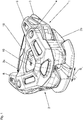
Fig. 1 eine Schrägansicht eines erfindungsgemäßen Vorderbackens einer Sicherheitsskibindung, -
Fig. 2 einen Horizontalschnitt eines erfindungsgemäßen Vorderbackens einer Sicherheitsskibindung ausFig. 1 , -
Fig. 3 ein Detail derFig. 2 , -
Fig. 4 eine Ansicht auf Bestandteile des Backens bei entferntem Gehäuseoberteil, -
Fig. 4a einen Horizontalschnitt durch den Backen in einer zuFig. 4 analogen Stellung des Backens, -
Fig. 5 eine Ansicht analog zuFig. 4 während einer Seitwärtsauslösung, -
Fig. 5a einen Horizontalschnitt analog zuFig. 4a während einer Seitwärtsauslösung, -
Fig. 6 ein Detail derFig. 4 ohne Feder und -
Fig. 7 ein Detail eines Vorderbackens mit einer Ausführungsvariante eines Druckelementes. - In einigen Figuren ist die bei an einem nicht dargestellten Ski montierter Skibindung gegebene Skilängsachse durch eine gestrichelte Linie, die mit SL bezeichnet ist, gekennzeichnet, die Richtung quer zur Skilängsachse SL, die Querrichtung Q, ist durch einen Doppelpfeil gekennzeichnet.
- Die Figuren zeigen, teilweise in Detailansichten, einen Vorderbacken 1 einer Skibindung, welcher zur Aufnahme des zehenseitigen Endes der Sohle eines nicht gezeigten Skischuhs vorgesehen ist. Zum Halten des rückwärtigen Endes der Skischuhsohle weist die Skibindung einen nicht dargestellten Fersenbacken auf. Bei einer Ausführung der Skibindung als reine Abfahrtsbindung werden sowohl der Vorderbacken 1 als auch der Fersenbacken auf herkömmliche Weise am nicht gezeigten Ski angeordnet bzw. befestigt. Bei einer Ausführung der Skibindung als Tourenbindung wird zumindest der Vorderbacken 1 auf einer nicht gezeigten, im Bereich des Vorderbackens 1 um eine Querachse drehbar gelagerten Tourenplatte angeordnet, welche im rückwärtigen Bereich auf lösbare Weise mit dem Ski verriegelbar ist.
- Der Vorderbacken 1 weist ein Gehäuse 2 mit einem Gehäuseoberteil 2a und einem Gehäuseunterteil 2b auf, welcher mit einer Grundplatte 3 versehen ist, mittels welcher der Vorderbacken 1 am Ski oder auf der Tourenplatte auf nicht gezeigte und an sich bekannte Weise angeordnet werden kann. Die Grundplatte 3 kann auch ein eigener Bauteil sein, welcher mit dem Gehäuse 2 fest verbunden, beispielsweise verschraubt ist. Gehäuseoberteil 2a und Gehäuseunterteil 2b sind miteinander fest verbunden, beispielsweise verschraubt, und bilden in ihrem Inneren gemeinsam eine Aufnahme für die weiter unten beschriebenen Bestandteile eines Auslösemechanismus.
- Am Gehäuse 2 sind symmetrisch zur Skilängsachse SL zwei in vertikaler Richtung verlaufende Bolzen 4 angeordnet, welche vertikal verlaufende Achsen zur schwenkbaren Lagerung von zweiarmigen Sohlenhaltern 5, 6 bilden und die Sohlenhalter 5, 6 durchsetzen. Jeder Sohlenhalter 5, 6 weist einen Arm 5a, 6a auf, welcher derart ausgebildet ist, dass er den vorderen Abschnitt der Sohle eines in den Vorderbacken 1 eingesetzten Skischuhs von oben und randseitig übergreift und seitlich an der Sohle anliegt. Der zweite Arm 5b, 6b beaufschlagt jeweils ein parallel zur Skilängsachse SL ausgerichtetes Druckelement 7, 8 (
Fig. 2 bis 6 ) bzw. 20 (Fig. 7 ), welches bei den dargestellten Ausführungsformen an seiner Außenseite eine ebene Gleitfläche für die Arme 5b, 6b zur Verfügung stellt. Die Druckelemente 7, 8 stehen Backen-innenseitig in noch zu beschreibender Weise unter der Wirkung einer Schraubendruckfeder 9, die in Querrichtung Q, demnach quer zur Skilängsachse SL zwischen den beiden Druckelementen 7, 8 verläuft. Jedes Druckelement 7, 8 sitzt auf einem Biegeblechstreifen 10, 11, welcher sich in Längsrichtung SL erstreckt und gebogene Endabschnitte 10a, 10b, 11a, 11b aufweist, derart, dass jeder Biegeblechstreifen 10, 11 in der Abfahrtsstellung bzw. der geschlossenen Lage (Fig. 2 ) des Vorderbackens 1, bezüglich der Skilängsachse SL betrachtet, insgesamt leicht konkav gekrümmt ist. Die Biegeblechstreifen 10, 11 tragen die Druckelemente 7, 8 und können von den Sohlenhaltern 5, 6 durch Ausüben von Druck auf die Druckelemente 7, 8 und unter gleichzeitiger Bewegung der Druckelemente 7, 8 in Querrichtung Q soweit verbogen werden, dass sie in der Auslösestellung (Fig. 5 ,Fig. 5a ) bezüglich der Skilängsachse SL konvex gebogen sind. - Das Druckelement 7 weist einen insbesondere scheibenförmig ausgebildeten Außenteil 7a und einen insbesondere zylindrisch gestalteten Ansatz 7b auf, welcher eine Öffnung im Biegeblechstreifen 10 durchsetzt und außenseitig mit einem Sicherungsring 7c fest verbunden ist. Sicherungsring 7c und Ansatz 7b bilden ein Positionierelement für den Endabschnitt der Feder 9.
- Das Druckelement 8 weist einen insbesondere scheibenförmig ausgeführten Außenteil 8a und einen ebenfalls etwa scheibenförmig gestalteten Innenteil 8b auf, wobei zwischen Außen- und Innenteil 8a, 8b der Biegeblechstreifen 11 gehalten ist. Der Außen- und der Innenteil 8a, 8b sind miteinander fest verbunden, beispielsweise über Schnappverbindungen.
- Der eine Endabschnitt 10a, 11a jedes Biegeblechstreifens 10, 11 ist am Gehäuse 2 gehalten, bei der gezeigten Ausführungsform an seinem Ende zusätzlich umgebogen und greift hinter einen Vorsprung 12 des Gehäuseunterteils 2b. Der zweite Endeabschnitt 10b, 11b jedes Biegeblechstreifens 10, 11 ist gegenüber dem Gehäuse 2 beweglich angeordnet, wobei im Gehäuse 2, bei der gezeigten Ausführung zwischen dem Gehäuseoberteil 2a und dem Gehäuseunterteil 2b, ein Freiraum vorhanden ist, sodass sich der Endabschnitt 10b, 11b in der Abfahrtsstellung (
Fig. 4a ) an einer Stützfläche des Gehäuseoberteils 2a und in der Auslösestellung (Fig. 5a ) an einer dieser gegenüberliegenden Stützfläche des Gehäuseunterteils 2b abstützt. Der Freiraum zwischen den Stützflächen ermöglicht die oben erwähnte Verformung der Biegeblechstreifen 10, 11 bei einer Auslösung. - Die Schraubendruckfeder 9 ist beim Druckelement 7 mit ihrem einen Ende am Biegeblechstreifen 10 abgestützt. Zwischen den beiden Druckelementen 7, 8 ist die Schraubendruckfeder 9 am Gehäuse 2, insbesondere an mehreren in Querrichtung verlaufenden, am Gehäuseoberteil 2a und am Gehäuseunterteil 2b ausgebildeten Führungsrippen 13, geführt.
- Das zweite Ende der Schraubendruckfeder 9 ist an einem Federwiderlager 14 abgestützt, welches über eine Stellschraube 15 am zweiten Druckelement 8 abgestützt ist und gegenüber diesem in Querrichtung Q verstellbar ist, um die Vorspannung der Schraubendruckfeder 9 zur Einstellung der Auslösekräfte der Sohlenhalter 5, 6 zu verändern. Das Federwiderlager 14 ist ein im Wesentlichen ringförmiger Bauteil, welcher eine zentrale Öffnung 14a mit einem Innengewinde aufweist, mittels welchem das Federwiderlager 14 auf einem Gewindeabschnitt der Stellschraube 15 sitzt, welche gegenüber dem Druckelement 8 drehbar ist. Der Schraubkopf 15a der Stellschraube 15 ist von der Außenseite des Druckelementes 8 zugänglich und mittels eines herkömmlichen Werkzeuges betätigbar. Das Federwiderlager 14 ist an seinem Außenumfang mit einem Führungsansatz 14b (
Fig. 6 ) versehen, welcher in eine am Gehäuse 2 ausgebildete Führungsnut 16 eingreift, sodass das Federwiderlager 14 unverdrehbar gehalten, jedoch in Querrichtung Q beweglich ist. Somit bewirkt ein Drehen der Stellschraube 15 eine entsprechende Längsbewegung des Federwiderlagers 14 an der Stellschraube 15 und damit eine Verstellung des gegenseitigen Abstandes zwischen dem Federwiderlager 14 und dem Druckelement 7. Das Federwiderlager 14 weist ferner am oberen Bereich seines Außenumfanges ein Anzeigeelement 17 auf, welches gemeinsam mit einer Skala 18 im Bereich eines Fensters 19 des Gehäuses 2 (Fig. 1 ) ein Ablesen der eingestellten Federvorspannung gestattet. - Bei einer Auslösung des Vorderbackens und einer damit einhergehenden Freigabe eines eingesetzten Skischuhs wird der vom Skischuh seitlich beaufschlagte Sohlenhalter - in
Fig. 5 und5a ist es der Sohlenhalter 5 - um seinen Bolzen 4 nach außen verschwenkt. Dabei drückt der Hebelarm 5b auf das Druckelement 7 und gleitet entlang der Außenseite des Druckelementes 7. Der Biegeblechstreifen 10 wird gleichzeitig in Querrichtung Q unter entsprechender Verformung und gemeinsam mit dem Druckelement 7 bewegt und komprimiert dabei die Schraubendruckfeder 9. Nach der Freigabe des Skischuhs wird der Sohlenhalter 5 unter der Wirkung der Schraubendruckfeder 9 wieder in seine Ausgangslage gebracht. Eine Freigabe des Skischuhs durch ein Verschwenken des anderen Sohlenhalters 6 erfolgt auf analoge Weise. - Zur Herstellung der Verbindung zwischen den Druckelementen 7, 8 und den Biegeblechstreifen 10, 11 können letztere auch mit Kunststoff umspritzt werden.
Das inFig. 7 gezeigte Ausführungsbeispiel unterscheidet sich von jener gemäß denFiguren 2 bis 6 durch die Ausführung der Druckelemente, von welchen nur jenes dargestellt ist, das kein verstellbares Federwiderlager trägt. Das Druckelement ist ein Biegeblechstreifen 20, dessen Funktion und Anordnung am Gehäuse 2 jener der Biegeblechstreifen 10, 11 entspricht und welcher an seiner Innenseite unmittelbar von der inFig. 7 nicht gezeigten Feder 9 beaufschlagt ist. Die Biegeblechstreifen 20 weisen ebene, mittige Abschnitte 20b auf, an welchen die Arme 5b, 6b der Sohlenhalter 5, 6 außenseitig abgestützt sind und entlang welcher die Arme 5b, 6b während eines Auslösevorganges gleiten. Als Positionierelement für die Feder 9 weist der inFig. 7 gezeigte Biegeblechstreifen 20 mittig eine Anzahl von im rechten Winkel abstehenden kurzen Blechflügeln 20a auf, die aus dem Material des Biegeblechstreifens 20 durch das Ausbilden eines mittigen Loches gebildet werden können. Am zweiten, nicht gezeigten Biegeblechstreifen 20 kann das verstellbare Federwiderlager analog zur ersten Ausführungsform angeordnet sein. - Die Biegeblechstreifen können auch derart ausgeführt sein, dass sie gerade sind oder konkav gebogen sind und bei einer Auslösung von dieser Form in eine konvexe oder mehr konkav gebogene Form gelangen. Wesentlich ist, dass sie gegen die Kraft der Feder 9 verbiegbar bzw. verformbar sind. Anstelle von ebenen Gleitflächen für die Arme 5b, 6b der Sohlenhalter 5, 6 können die Druckelemente 7, 8, 20 auch speziell geformte Steuerflächen aufweisen, um die Auslösecharakteristik zu beeinflussen.
-
- 1 ............................
- Vorderbacken
- 2 ............................
- Gehäuse
- 2a ..........................
- Gehäuseoberteil
- 2b ..........................
- Gehäuseunterteil
- 3 ............................
- Grundplatte
- 4 ............................
- Bolzen
- 5 ............................
- Sohlenhalter
- 5a, 5b ....................
- Hebelarm
- 6 ............................
- Sohlenhalter
- 6a, 6b ....................
- Hebelarm
- 7 ............................
- Druckelement
- 7a ..........................
- Außenteil
- 7b ..........................
- Ansatz
- 7c ..........................
- Sicherungsring
- 8 ............................
- Druckelement
- 8a ..........................
- Außenteil
- 8b ..........................
- Innenteil
- 9 ............................
- Schraubendruckfeder
- 10 ..........................
- Biegeblechstreifen
- 10a, 10b ................
- Endabschnitt
- 11 ..........................
- Biegeblechstreifen
- 11a, 11b ................
- Endabschnitt
- 12 ..........................
- Ansatz
- 13 ..........................
- Führungsrippe
- 14 ..........................
- Federwiderlager
- 14a ........................
- Bohrung
- 14b ........................
- Führungsansatz
- 15 ..........................
- Stellschraube
- 15a ........................
- Schaubkopf
- 16 ..........................
- Führungsnut
- 17 ..........................
- Anzeigeelement
- 18 ..........................
- Skala
- 19 ..........................
- Fenster
- 20 ..........................
- Biegeblechstreifen
- 20a ........................
- Blechflügel
- 20b ........................
- mittiger Abschnitt
- Q ...........................
- Skiquerrichtung
- SL ..........................
- Skilängsachse
Claims (12)
- Vorderbacken (1) einer Skibindung mit einem Gehäuse (2) und mit zwei am Gehäuse (2) angeordneten, um vertikale Hochachsen schwenkbaren Sohlenhaltern (5, 6), welche als zweiarmige Hebel ausgebildet sind, deren eine Hebelarme (5a, 6a) den vorderen Endbereich des Sohlenrandes eines Skischuhs halten und deren zweite Hebelarme (5b, 6b) mit Druckelementen (7, 8, 20) zusammenwirken, die in Skiquerrichtung (Q) bewegbar sind und von einer zwischen ihnen befindlichen, sich in Skiquerrichtung (Q) erstreckenden Feder (9) beaufschlagt sind,
dadurch gekennzeichnet,
dass die Feder (9) an einzelnen, in Skiquerrichtung (Q) am Gehäuse (2) oder an einem gehäusefesten Teil ausgebildeten Führungsrippen (13) geführt ist und dass die Druckelemente (7, 8, 20) von Biegeblechstreifen (10, 11) getragen oder gebildet sind, welche am Gehäuse (2) beweglich gelagert sind und bei einer Auslösung verformbar bzw. verbiegbar sind. - Vorderbacken (1) nach Anspruch 1, dadurch gekennzeichnet, dass die Biegeblechstreifen (10, 11) zumindest abschnittsweise gebogen ausgeführt sind.
- Vorderbacken (1) nach Anspruch 1 oder 2, dadurch gekennzeichnet, dass die Biegeblechstreifen (10, 11), in der geschlossenen Lage des Vorderbackens (1) und bezüglich der Skilängsachse (SL) betrachtet, konkav gebogen sind.
- Vorderbacken (1) nach einem der Ansprüche 1 bis 3, dadurch gekennzeichnet, dass die Druckelemente (7, 8) mit den Biegeblechstreifen (10, 11) fest verbunden sind
- Vorderbacken (1) nach einem der Ansprüche 1 bis 4, dadurch gekennzeichnet, dass die Druckelemente (7, 8, 20) an ihrer Außenseite eine Gleitfläche für die zweiten Hebelarme (5b, 6b) der Sohlenhalter (5, 6) aufweisen, welche eine ebene Fläche oder eine geformte Steuerfläche ist.
- Vorderbacken (1) nach einem der Ansprüche 1 bis 5, dadurch gekennzeichnet, dass die Druckelemente (7, 8) scheibenartig ausgeführte Außenteile (7a, 8a) aufweisen, an deren Außenseiten die Gleitflächen ausgebildet sind.
- Vorderbacken (1) nach einem der Ansprüche 1 bis 5, dadurch gekennzeichnet, dass jeder Biegeblechstreifen (10, 11, 20) mit seinem einen Ende im Gehäuse (2) verankert, beispielsweise eingehängt, ist und mit seinem zweiten Ende im Gehäuse (2), in Skiquerrichtung (Q) beweglich, gelagert ist.
- Vorderbacken (1) nach einem der Ansprüche 1 bis 7, dadurch gekennzeichnet, dass die Feder (9) das eine Druckelement (7) oder den Biegeblechstreifen (10, 20) unmittelbar und das zweite Druckelement (8) oder den Biegeblechstreifen (20) über ein verstellbares Federwiderlager (14) beaufschlagt.
- Vorderbacken (1) nach einem der Ansprüche 1 bis 8, dadurch gekennzeichnet, dass das von der Feder (9) unmittelbar beaufschlagte Druckelement (7) oder der von der Feder (9) unmittelbar beaufschlagte Biegeblechstreifen (10, 20) an seiner Innenseite ein Positionierelement (7c, 20a) für den Endabschnitt der Feder (9) aufweist.
- Vorderbacken (1) nach Anspruch 9, dadurch gekennzeichnet, dass das Positionierelement ein zylindrischer Teil (7b, 7c) an der Innenseite des Druckelementes (7) ist.
- Vorderbacken (1) nach Anspruch 9, dadurch gekennzeichnet, dass das Positionierelement von ringartig angeordneten Blechflügeln (20a) des Biegeblechstreifens (20) gebildet ist.
- Vorderbacken (1) nach einem der Ansprüche 1 bis 11, dadurch gekennzeichnet, dass das verstellbare Federwiderlager (14) auf einer von der Feder (9) an das Druckelement (8) bzw. den Biegeblechstreifen (20) gedrückten Stellschraube (15) in Skiquerrichtung (Q) verstellbar und gegenüber dem Gehäuse (2) axial unverdrehbar gelagert ist.
Applications Claiming Priority (1)
| Application Number | Priority Date | Filing Date | Title |
|---|---|---|---|
| ATA50225/2014A AT515560B1 (de) | 2014-03-28 | 2014-03-28 | Vorderbacken |
Publications (2)
| Publication Number | Publication Date |
|---|---|
| EP2923742A1 EP2923742A1 (de) | 2015-09-30 |
| EP2923742B1 true EP2923742B1 (de) | 2017-03-01 |
Family
ID=52706009
Family Applications (1)
| Application Number | Title | Priority Date | Filing Date |
|---|---|---|---|
| EP15159136.9A Active EP2923742B1 (de) | 2014-03-28 | 2015-03-16 | Vorderbacken |
Country Status (2)
| Country | Link |
|---|---|
| EP (1) | EP2923742B1 (de) |
| AT (1) | AT515560B1 (de) |
Families Citing this family (1)
| Publication number | Priority date | Publication date | Assignee | Title |
|---|---|---|---|---|
| US11524220B2 (en) * | 2018-07-09 | 2022-12-13 | Ryan PRIEST | Ski binding |
Family Cites Families (8)
| Publication number | Priority date | Publication date | Assignee | Title |
|---|---|---|---|---|
| DE1428937A1 (de) * | 1964-08-25 | 1969-02-13 | Miller Earl Andrew | Sicherheitsskibindung |
| DE1963149A1 (de) * | 1969-12-17 | 1971-06-24 | Ludwig Berchtold | Sicherheitsvorderbacken fuer Skibindungen |
| FR2201107A1 (de) * | 1972-09-27 | 1974-04-26 | Salomon Georges P J | |
| FR2717705B1 (fr) * | 1994-03-24 | 1996-06-07 | Frederic Paradis | Butée avant pour fixation de sécurité de ski alpin. |
| DE102006039989B4 (de) * | 2006-08-25 | 2015-10-08 | Marker Deutschland Gmbh | Schuhhalteraggregat einer Skibindung |
| DE102008050884A1 (de) * | 2008-10-09 | 2010-04-15 | Marker Deutschland Gmbh | Schuhhalteraggregat einer Skibindung |
| FR2952308B1 (fr) * | 2009-11-12 | 2013-07-12 | Salomon Sas | Butee avant pour fixation de securite destinee a etre fixee a un ski |
| FR2966747B1 (fr) * | 2010-10-29 | 2013-01-11 | Salomon Sas | Fixation de securite pour la pratique du ski. |
-
2014
- 2014-03-28 AT ATA50225/2014A patent/AT515560B1/de not_active IP Right Cessation
-
2015
- 2015-03-16 EP EP15159136.9A patent/EP2923742B1/de active Active
Also Published As
| Publication number | Publication date |
|---|---|
| AT515560B1 (de) | 2016-02-15 |
| EP2923742A1 (de) | 2015-09-30 |
| AT515560A1 (de) | 2015-10-15 |
Similar Documents
| Publication | Publication Date | Title |
|---|---|---|
| EP3880926B1 (de) | Führungssystem zur führung eines bewegbar gelagerten türflügels | |
| DE2655896C2 (de) | Sicherheitsbindung für Ski mit einem Backen | |
| EP2527576A1 (de) | Scharnier insbesondere für eine Verschiebevorrichtung | |
| EP3613931B1 (de) | Baugruppe eines bandes zur um eine scharnierachse scharnierbeweglichen verbindung eines flügels an einem rahmen | |
| EP3088645A1 (de) | Verbindungsvorrichtung für eine schiebetür | |
| CH657109A5 (de) | Traggestell. | |
| EP3103948A1 (de) | Band für eine tür oder ein fenster | |
| DE3141248A1 (de) | "motorbetreibbarer schraubenzieher" | |
| EP2923742B1 (de) | Vorderbacken | |
| DE7533447U (de) | Vorrichtung zum veredeln von pflanzen, insbesondere von weinreben | |
| DE2359490B2 (de) | Vorderer Bindungsteil einer Sicherheitsbindung für Ski | |
| EP2951374B1 (de) | Laufteil zum führen eines möbelteils in einer führungsrichtung über eine führungsschiene und möbelbeschlag | |
| EP3667010A1 (de) | Anschlagvorrichtung für eine automatische türdichtung, insbesondere für eine pivot- oder pendeltür, anordnung aus einer automatischen türdichtung und einer anschlagvorrichtung | |
| EP3175068A1 (de) | Beschlaganordnung | |
| DE2910508C2 (de) | Sicherheitsbindung für Ski | |
| EP3183408B1 (de) | Steuerelement für eine beschlaganordnung | |
| DE2559656A1 (de) | Anordnung mit einem einstellbaren kniehebelmechanismus, insbesondere bei zangen u.dgl. | |
| EP1734330B1 (de) | Montagevorrichtung für ein Zielfernrohr | |
| EP3095492B1 (de) | Vorderbacken für eine sicherheitsskibindung | |
| EP4417276B1 (de) | Vorderbacken und sicherheitsskibindung mit einem vorderbacken | |
| DE2326280C2 (de) | Vorrichtung zum Abisolieren der Isolierung von Leiterenden | |
| DE102014112072B4 (de) | Flügelheber | |
| DE102012222210A1 (de) | Zur verdeckten Anordnung vorgesehenes Ecklager | |
| DE10030325C2 (de) | Gleitstück | |
| DE2835732C3 (de) | Sicherheitsskibindung |
Legal Events
| Date | Code | Title | Description |
|---|---|---|---|
| PUAI | Public reference made under article 153(3) epc to a published international application that has entered the european phase |
Free format text: ORIGINAL CODE: 0009012 |
|
| AK | Designated contracting states |
Kind code of ref document: A1 Designated state(s): AL AT BE BG CH CY CZ DE DK EE ES FI FR GB GR HR HU IE IS IT LI LT LU LV MC MK MT NL NO PL PT RO RS SE SI SK SM TR |
|
| AX | Request for extension of the european patent |
Extension state: BA ME |
|
| 17P | Request for examination filed |
Effective date: 20160224 |
|
| RBV | Designated contracting states (corrected) |
Designated state(s): AL AT BE BG CH CY CZ DE DK EE ES FI FR GB GR HR HU IE IS IT LI LT LU LV MC MK MT NL NO PL PT RO RS SE SI SK SM TR |
|
| GRAP | Despatch of communication of intention to grant a patent |
Free format text: ORIGINAL CODE: EPIDOSNIGR1 |
|
| INTG | Intention to grant announced |
Effective date: 20161118 |
|
| GRAS | Grant fee paid |
Free format text: ORIGINAL CODE: EPIDOSNIGR3 |
|
| GRAA | (expected) grant |
Free format text: ORIGINAL CODE: 0009210 |
|
| AK | Designated contracting states |
Kind code of ref document: B1 Designated state(s): AL AT BE BG CH CY CZ DE DK EE ES FI FR GB GR HR HU IE IS IT LI LT LU LV MC MK MT NL NO PL PT RO RS SE SI SK SM TR |
|
| REG | Reference to a national code |
Ref country code: GB Ref legal event code: FG4D Free format text: NOT ENGLISH |
|
| REG | Reference to a national code |
Ref country code: CH Ref legal event code: EP Ref country code: AT Ref legal event code: REF Ref document number: 870597 Country of ref document: AT Kind code of ref document: T Effective date: 20170315 |
|
| REG | Reference to a national code |
Ref country code: IE Ref legal event code: FG4D Free format text: LANGUAGE OF EP DOCUMENT: GERMAN |
|
| REG | Reference to a national code |
Ref country code: FR Ref legal event code: PLFP Year of fee payment: 3 |
|
| REG | Reference to a national code |
Ref country code: DE Ref legal event code: R096 Ref document number: 502015000618 Country of ref document: DE |
|
| REG | Reference to a national code |
Ref country code: NL Ref legal event code: MP Effective date: 20170301 |
|
| REG | Reference to a national code |
Ref country code: LT Ref legal event code: MG4D |
|
| PG25 | Lapsed in a contracting state [announced via postgrant information from national office to epo] |
Ref country code: NO Free format text: LAPSE BECAUSE OF FAILURE TO SUBMIT A TRANSLATION OF THE DESCRIPTION OR TO PAY THE FEE WITHIN THE PRESCRIBED TIME-LIMIT Effective date: 20170601 Ref country code: FI Free format text: LAPSE BECAUSE OF FAILURE TO SUBMIT A TRANSLATION OF THE DESCRIPTION OR TO PAY THE FEE WITHIN THE PRESCRIBED TIME-LIMIT Effective date: 20170301 Ref country code: HR Free format text: LAPSE BECAUSE OF FAILURE TO SUBMIT A TRANSLATION OF THE DESCRIPTION OR TO PAY THE FEE WITHIN THE PRESCRIBED TIME-LIMIT Effective date: 20170301 Ref country code: GR Free format text: LAPSE BECAUSE OF FAILURE TO SUBMIT A TRANSLATION OF THE DESCRIPTION OR TO PAY THE FEE WITHIN THE PRESCRIBED TIME-LIMIT Effective date: 20170602 Ref country code: LT Free format text: LAPSE BECAUSE OF FAILURE TO SUBMIT A TRANSLATION OF THE DESCRIPTION OR TO PAY THE FEE WITHIN THE PRESCRIBED TIME-LIMIT Effective date: 20170301 |
|
| PG25 | Lapsed in a contracting state [announced via postgrant information from national office to epo] |
Ref country code: ES Free format text: LAPSE BECAUSE OF FAILURE TO SUBMIT A TRANSLATION OF THE DESCRIPTION OR TO PAY THE FEE WITHIN THE PRESCRIBED TIME-LIMIT Effective date: 20170301 Ref country code: LV Free format text: LAPSE BECAUSE OF FAILURE TO SUBMIT A TRANSLATION OF THE DESCRIPTION OR TO PAY THE FEE WITHIN THE PRESCRIBED TIME-LIMIT Effective date: 20170301 Ref country code: BG Free format text: LAPSE BECAUSE OF FAILURE TO SUBMIT A TRANSLATION OF THE DESCRIPTION OR TO PAY THE FEE WITHIN THE PRESCRIBED TIME-LIMIT Effective date: 20170601 Ref country code: RS Free format text: LAPSE BECAUSE OF FAILURE TO SUBMIT A TRANSLATION OF THE DESCRIPTION OR TO PAY THE FEE WITHIN THE PRESCRIBED TIME-LIMIT Effective date: 20170301 Ref country code: SE Free format text: LAPSE BECAUSE OF FAILURE TO SUBMIT A TRANSLATION OF THE DESCRIPTION OR TO PAY THE FEE WITHIN THE PRESCRIBED TIME-LIMIT Effective date: 20170301 |
|
| PG25 | Lapsed in a contracting state [announced via postgrant information from national office to epo] |
Ref country code: NL Free format text: LAPSE BECAUSE OF FAILURE TO SUBMIT A TRANSLATION OF THE DESCRIPTION OR TO PAY THE FEE WITHIN THE PRESCRIBED TIME-LIMIT Effective date: 20170301 |
|
| PG25 | Lapsed in a contracting state [announced via postgrant information from national office to epo] |
Ref country code: SK Free format text: LAPSE BECAUSE OF FAILURE TO SUBMIT A TRANSLATION OF THE DESCRIPTION OR TO PAY THE FEE WITHIN THE PRESCRIBED TIME-LIMIT Effective date: 20170301 Ref country code: CZ Free format text: LAPSE BECAUSE OF FAILURE TO SUBMIT A TRANSLATION OF THE DESCRIPTION OR TO PAY THE FEE WITHIN THE PRESCRIBED TIME-LIMIT Effective date: 20170301 Ref country code: IT Free format text: LAPSE BECAUSE OF FAILURE TO SUBMIT A TRANSLATION OF THE DESCRIPTION OR TO PAY THE FEE WITHIN THE PRESCRIBED TIME-LIMIT Effective date: 20170301 Ref country code: RO Free format text: LAPSE BECAUSE OF FAILURE TO SUBMIT A TRANSLATION OF THE DESCRIPTION OR TO PAY THE FEE WITHIN THE PRESCRIBED TIME-LIMIT Effective date: 20170301 Ref country code: EE Free format text: LAPSE BECAUSE OF FAILURE TO SUBMIT A TRANSLATION OF THE DESCRIPTION OR TO PAY THE FEE WITHIN THE PRESCRIBED TIME-LIMIT Effective date: 20170301 |
|
| PG25 | Lapsed in a contracting state [announced via postgrant information from national office to epo] |
Ref country code: PT Free format text: LAPSE BECAUSE OF FAILURE TO SUBMIT A TRANSLATION OF THE DESCRIPTION OR TO PAY THE FEE WITHIN THE PRESCRIBED TIME-LIMIT Effective date: 20170703 Ref country code: IS Free format text: LAPSE BECAUSE OF FAILURE TO SUBMIT A TRANSLATION OF THE DESCRIPTION OR TO PAY THE FEE WITHIN THE PRESCRIBED TIME-LIMIT Effective date: 20170701 Ref country code: PL Free format text: LAPSE BECAUSE OF FAILURE TO SUBMIT A TRANSLATION OF THE DESCRIPTION OR TO PAY THE FEE WITHIN THE PRESCRIBED TIME-LIMIT Effective date: 20170301 Ref country code: SM Free format text: LAPSE BECAUSE OF FAILURE TO SUBMIT A TRANSLATION OF THE DESCRIPTION OR TO PAY THE FEE WITHIN THE PRESCRIBED TIME-LIMIT Effective date: 20170301 |
|
| REG | Reference to a national code |
Ref country code: DE Ref legal event code: R097 Ref document number: 502015000618 Country of ref document: DE |
|
| REG | Reference to a national code |
Ref country code: IE Ref legal event code: MM4A |
|
| PLBE | No opposition filed within time limit |
Free format text: ORIGINAL CODE: 0009261 |
|
| STAA | Information on the status of an ep patent application or granted ep patent |
Free format text: STATUS: NO OPPOSITION FILED WITHIN TIME LIMIT |
|
| PG25 | Lapsed in a contracting state [announced via postgrant information from national office to epo] |
Ref country code: MC Free format text: LAPSE BECAUSE OF FAILURE TO SUBMIT A TRANSLATION OF THE DESCRIPTION OR TO PAY THE FEE WITHIN THE PRESCRIBED TIME-LIMIT Effective date: 20170301 Ref country code: LU Free format text: LAPSE BECAUSE OF NON-PAYMENT OF DUE FEES Effective date: 20170316 Ref country code: DK Free format text: LAPSE BECAUSE OF FAILURE TO SUBMIT A TRANSLATION OF THE DESCRIPTION OR TO PAY THE FEE WITHIN THE PRESCRIBED TIME-LIMIT Effective date: 20170301 |
|
| 26N | No opposition filed |
Effective date: 20171204 |
|
| PG25 | Lapsed in a contracting state [announced via postgrant information from national office to epo] |
Ref country code: SI Free format text: LAPSE BECAUSE OF FAILURE TO SUBMIT A TRANSLATION OF THE DESCRIPTION OR TO PAY THE FEE WITHIN THE PRESCRIBED TIME-LIMIT Effective date: 20170301 Ref country code: IE Free format text: LAPSE BECAUSE OF NON-PAYMENT OF DUE FEES Effective date: 20170316 |
|
| REG | Reference to a national code |
Ref country code: BE Ref legal event code: MM Effective date: 20170331 |
|
| REG | Reference to a national code |
Ref country code: FR Ref legal event code: PLFP Year of fee payment: 4 |
|
| PG25 | Lapsed in a contracting state [announced via postgrant information from national office to epo] |
Ref country code: BE Free format text: LAPSE BECAUSE OF NON-PAYMENT OF DUE FEES Effective date: 20170331 |
|
| PG25 | Lapsed in a contracting state [announced via postgrant information from national office to epo] |
Ref country code: MT Free format text: LAPSE BECAUSE OF FAILURE TO SUBMIT A TRANSLATION OF THE DESCRIPTION OR TO PAY THE FEE WITHIN THE PRESCRIBED TIME-LIMIT Effective date: 20170301 |
|
| PG25 | Lapsed in a contracting state [announced via postgrant information from national office to epo] |
Ref country code: HU Free format text: LAPSE BECAUSE OF FAILURE TO SUBMIT A TRANSLATION OF THE DESCRIPTION OR TO PAY THE FEE WITHIN THE PRESCRIBED TIME-LIMIT; INVALID AB INITIO Effective date: 20150316 |
|
| PG25 | Lapsed in a contracting state [announced via postgrant information from national office to epo] |
Ref country code: CY Free format text: LAPSE BECAUSE OF FAILURE TO SUBMIT A TRANSLATION OF THE DESCRIPTION OR TO PAY THE FEE WITHIN THE PRESCRIBED TIME-LIMIT Effective date: 20170301 |
|
| GBPC | Gb: european patent ceased through non-payment of renewal fee |
Effective date: 20190316 |
|
| PG25 | Lapsed in a contracting state [announced via postgrant information from national office to epo] |
Ref country code: MK Free format text: LAPSE BECAUSE OF FAILURE TO SUBMIT A TRANSLATION OF THE DESCRIPTION OR TO PAY THE FEE WITHIN THE PRESCRIBED TIME-LIMIT Effective date: 20170301 |
|
| PG25 | Lapsed in a contracting state [announced via postgrant information from national office to epo] |
Ref country code: GB Free format text: LAPSE BECAUSE OF NON-PAYMENT OF DUE FEES Effective date: 20190316 |
|
| PG25 | Lapsed in a contracting state [announced via postgrant information from national office to epo] |
Ref country code: TR Free format text: LAPSE BECAUSE OF FAILURE TO SUBMIT A TRANSLATION OF THE DESCRIPTION OR TO PAY THE FEE WITHIN THE PRESCRIBED TIME-LIMIT Effective date: 20170301 |
|
| PG25 | Lapsed in a contracting state [announced via postgrant information from national office to epo] |
Ref country code: AL Free format text: LAPSE BECAUSE OF FAILURE TO SUBMIT A TRANSLATION OF THE DESCRIPTION OR TO PAY THE FEE WITHIN THE PRESCRIBED TIME-LIMIT Effective date: 20170301 |
|
| PGFP | Annual fee paid to national office [announced via postgrant information from national office to epo] |
Ref country code: FR Payment date: 20230324 Year of fee payment: 9 Ref country code: AT Payment date: 20230322 Year of fee payment: 9 |
|
| PGFP | Annual fee paid to national office [announced via postgrant information from national office to epo] |
Ref country code: DE Payment date: 20230321 Year of fee payment: 9 |
|
| PGFP | Annual fee paid to national office [announced via postgrant information from national office to epo] |
Ref country code: CH Payment date: 20230401 Year of fee payment: 9 |
|
| REG | Reference to a national code |
Ref country code: DE Ref legal event code: R119 Ref document number: 502015000618 Country of ref document: DE |
|
| REG | Reference to a national code |
Ref country code: CH Ref legal event code: PL |
|
| REG | Reference to a national code |
Ref country code: AT Ref legal event code: MM01 Ref document number: 870597 Country of ref document: AT Kind code of ref document: T Effective date: 20240316 |
|
| PG25 | Lapsed in a contracting state [announced via postgrant information from national office to epo] |
Ref country code: DE Free format text: LAPSE BECAUSE OF NON-PAYMENT OF DUE FEES Effective date: 20241001 |
|
| PG25 | Lapsed in a contracting state [announced via postgrant information from national office to epo] |
Ref country code: FR Free format text: LAPSE BECAUSE OF NON-PAYMENT OF DUE FEES Effective date: 20240331 |
|
| PG25 | Lapsed in a contracting state [announced via postgrant information from national office to epo] |
Ref country code: AT Free format text: LAPSE BECAUSE OF NON-PAYMENT OF DUE FEES Effective date: 20240316 |
|
| PG25 | Lapsed in a contracting state [announced via postgrant information from national office to epo] |
Ref country code: FR Free format text: LAPSE BECAUSE OF NON-PAYMENT OF DUE FEES Effective date: 20240331 Ref country code: DE Free format text: LAPSE BECAUSE OF NON-PAYMENT OF DUE FEES Effective date: 20241001 Ref country code: AT Free format text: LAPSE BECAUSE OF NON-PAYMENT OF DUE FEES Effective date: 20240316 Ref country code: CH Free format text: LAPSE BECAUSE OF NON-PAYMENT OF DUE FEES Effective date: 20240331 |