EP2923779A1 - Zaunpaneel - Google Patents
Zaunpaneel Download PDFInfo
- Publication number
- EP2923779A1 EP2923779A1 EP14161734.0A EP14161734A EP2923779A1 EP 2923779 A1 EP2923779 A1 EP 2923779A1 EP 14161734 A EP14161734 A EP 14161734A EP 2923779 A1 EP2923779 A1 EP 2923779A1
- Authority
- EP
- European Patent Office
- Prior art keywords
- wires
- fence
- fence panel
- beams
- vertical
- Prior art date
- Legal status (The legal status is an assumption and is not a legal conclusion. Google has not performed a legal analysis and makes no representation as to the accuracy of the status listed.)
- Withdrawn
Links
- 238000000034 method Methods 0.000 claims description 17
- 239000002184 metal Substances 0.000 claims description 12
- 238000004519 manufacturing process Methods 0.000 claims description 11
- 229910052751 metal Inorganic materials 0.000 claims description 11
- 238000005452 bending Methods 0.000 claims description 5
- 238000005520 cutting process Methods 0.000 claims description 4
- 239000004035 construction material Substances 0.000 claims description 3
- 238000000576 coating method Methods 0.000 description 6
- 239000011248 coating agent Substances 0.000 description 5
- 239000000463 material Substances 0.000 description 5
- XEEYBQQBJWHFJM-UHFFFAOYSA-N Iron Chemical compound [Fe] XEEYBQQBJWHFJM-UHFFFAOYSA-N 0.000 description 4
- 238000003466 welding Methods 0.000 description 4
- 238000010276 construction Methods 0.000 description 3
- 229910000831 Steel Inorganic materials 0.000 description 2
- 238000010924 continuous production Methods 0.000 description 2
- 230000001419 dependent effect Effects 0.000 description 2
- 238000009795 derivation Methods 0.000 description 2
- 229910052742 iron Inorganic materials 0.000 description 2
- 229910001092 metal group alloy Inorganic materials 0.000 description 2
- 239000010959 steel Substances 0.000 description 2
- 229910001369 Brass Inorganic materials 0.000 description 1
- 229910000906 Bronze Inorganic materials 0.000 description 1
- RYGMFSIKBFXOCR-UHFFFAOYSA-N Copper Chemical compound [Cu] RYGMFSIKBFXOCR-UHFFFAOYSA-N 0.000 description 1
- 239000004411 aluminium Substances 0.000 description 1
- 229910052782 aluminium Inorganic materials 0.000 description 1
- XAGFODPZIPBFFR-UHFFFAOYSA-N aluminium Chemical compound [Al] XAGFODPZIPBFFR-UHFFFAOYSA-N 0.000 description 1
- 239000010951 brass Substances 0.000 description 1
- 239000010974 bronze Substances 0.000 description 1
- 239000010949 copper Substances 0.000 description 1
- 229910052802 copper Inorganic materials 0.000 description 1
- KUNSUQLRTQLHQQ-UHFFFAOYSA-N copper tin Chemical compound [Cu].[Sn] KUNSUQLRTQLHQQ-UHFFFAOYSA-N 0.000 description 1
- 238000011065 in-situ storage Methods 0.000 description 1
- 230000001788 irregular Effects 0.000 description 1
- 229910044991 metal oxide Inorganic materials 0.000 description 1
- 150000004706 metal oxides Chemical class 0.000 description 1
- 239000003607 modifier Substances 0.000 description 1
- 229920000642 polymer Polymers 0.000 description 1
- 239000000843 powder Substances 0.000 description 1
- 238000003825 pressing Methods 0.000 description 1
- 230000000087 stabilizing effect Effects 0.000 description 1
- 230000002123 temporal effect Effects 0.000 description 1
Images
Classifications
-
- E—FIXED CONSTRUCTIONS
- E04—BUILDING
- E04H—BUILDINGS OR LIKE STRUCTURES FOR PARTICULAR PURPOSES; SWIMMING OR SPLASH BATHS OR POOLS; MASTS; FENCING; TENTS OR CANOPIES, IN GENERAL
- E04H17/00—Fencing, e.g. fences, enclosures, corrals
- E04H17/14—Fences constructed of rigid elements, e.g. with additional wire fillings or with posts
- E04H17/16—Fences constructed of rigid elements, e.g. with additional wire fillings or with posts using prefabricated panel-like elements, e.g. wired frames
- E04H17/161—Fences constructed of rigid elements, e.g. with additional wire fillings or with posts using prefabricated panel-like elements, e.g. wired frames using wire panels
-
- B—PERFORMING OPERATIONS; TRANSPORTING
- B21—MECHANICAL METAL-WORKING WITHOUT ESSENTIALLY REMOVING MATERIAL; PUNCHING METAL
- B21F—WORKING OR PROCESSING OF METAL WIRE
- B21F27/00—Making wire network, i.e. wire nets
- B21F27/08—Making wire network, i.e. wire nets with additional connecting elements or material at crossings
- B21F27/10—Making wire network, i.e. wire nets with additional connecting elements or material at crossings with soldered or welded crossings
-
- B—PERFORMING OPERATIONS; TRANSPORTING
- B21—MECHANICAL METAL-WORKING WITHOUT ESSENTIALLY REMOVING MATERIAL; PUNCHING METAL
- B21F—WORKING OR PROCESSING OF METAL WIRE
- B21F29/00—Making fencing or like material made partly of wire
Definitions
- the present invention relates to fence panels, more particularly wire fence panels, methods for the production of fence panels, and fences comprising such fence panels.
- Wire fencing is widely used for a large number of residential, commercial and security applications.
- Conventional wire fencing is typically built using a number of fence panels, which generally are formed by a mesh of metal wires.
- the meshed structure of the fence panels allows manufacturing the panels using a minimal amount of materials and provides visibility through the fence, while providing sufficient rigidity and stability. Nevertheless, the panels still need additional support. Therefore, the fence panels are typically supported by fence posts, which are positioned between two adjacent fence panels.
- Fence panels are typically known in two forms, more particularly "three-dimensional” (3D) fence panels (which include “V-beam” fence panels) wherein the vertical wires of the panels are provided with bends which form horizontal beams; and “double wire panels” which comprise a meshed structure with a set of wires in a first direction, sandwiched between opposed pairs of wires in a second direction, typically orthogonal to the first direction.
- 3D three-dimensional
- double wire panels which comprise a meshed structure with a set of wires in a first direction, sandwiched between opposed pairs of wires in a second direction, typically orthogonal to the first direction.
- Conventional 3D panels and double wire panels typically have a width of at most 250 cm. Further increasing the width results in a significant decrease of the rigidity and stability of the panels, which negatively affects the panel lifetime.
- conventional wire fences are typically provided with fence post at intervals of 250 cm. A reduction of the number of fence posts needed for the construction of wire fences would represent a significant reduction in the amount of materials and time required for fence assembly. It is an object of the present invention to provide fence panels which allow for assembling wire fences with a reduced number of fence posts. It is a further object of the present invention to provide fence panels having a high rigidity and stability, even when the width exceeds 250 cm.
- the present invention relates to fence panels, more particularly wire fence panels, and methods for the production thereof.
- the present inventors have found that by combining the features of 3D panels (the presence of horizontal bends) and double wire panels (wires sandwiched between opposed pairs of wires), fence panels can be made which show a remarkable rigidity and stability.
- the present invention provides a fence panel having opposed first and second sides, comprising
- the fence panel is a three-dimensional fence panel, preferably a V-beam fence panel.
- each of the beams is provided with at least three pairs of opposing horizontal wires.
- the beams are positioned at intervals of between 400 mm and 1000 mm.
- the beams have a triangular transverse cross-section having an apex angle between 90 ° and 165°.
- the vertical wires and the horizontal wires have a diameter between 3 mm and 10 mm.
- the distance between adjacent vertical wires is between 10 mm and 100 mm.
- the distance between two adjacent pairs of opposing horizontal wires plane is:
- the vertical wires form at least three beams protruding from said plane, said beams extending horizontally along said fence panel.
- the horizontal wires and the vertical wires are made of metal.
- a method for manufacturing a fence panel as described herein comprising:
- step (i) comprises unwinding said plurality of wires from a plurality of roles.
- a fence comprising a plurality of fence panels as described herein, supported by posts.
- the panels described herein may have a width exceeding 250 cm, while still having the required rigidity and stability required to ensure a panel lifetime comparable to conventional panels.
- the increased panel width can result in a reduced amount of posts needed per unit of length when compared to conventional panels. This results in a decrease of the time needed for assembling the fence.
- the posts are a relative expensive component of wire fences, the reduction of the number of posts also allows for a more economical manufacture of fence components per unit of length.
- the present invention relates to fence panels.
- the fence panels described herein are wire fence panels.
- the panels have a meshed structure made of vertical wires which are sandwiched between opposing pairs of horizontal wires.
- the fence panels described herein are further characterized in that the vertical wires are provided with corrugations, thereby forming at least two horizontal beams.
- the combination of the sandwiched wires and the presence of two or more horizontal beams results in a significant enhancement of the rigidity and stability of the panels. More particularly, the panels show an increased resistance to bending and torsion.
- any reference to the "horizontal" or “vertical” orientation of an element of a fence panel, such as a wire or beam, will be understood to refer to the orientation of said element when the fence panel is in its operative upright orientation.
- the panels described herein comprise wires which are oriented in a first direction (vertical wires) which are sandwiched between wires which are oriented in a second direction orthogonal to the first direction (horizontal wires).
- orthogonal or perpendicular as used herein is to be understood as including a certain amount of derivation from its actual precise orientation. More particularly, two wires are considered having an orthogonal orientation relative to each other if the angle between the longitudinal axis of the wires is between 87° and 93°, more preferably between 89° and 91 °, most preferably about 90°. Similarly, the term “parallel” as used herein is to be understood as including a certain amount of derivation from its actual precise orientation. More particularly, two wires are considered parallel if the angle between the wires does not exceed 3°, more preferably 1 °, most preferably about 0°.
- the fence panel described herein also referred herein as "panel”
- the fence panel described herein comprises a set of vertical wires which are arranged in a plane.
- the vertical wires run in a single direction and therefore are positioned parallel to each other.
- the distance between two adjacent vertical wires can be dependent on the specific application of the fence.
- the vertical wires are equally spaced apart, i.e. the distance between two adjacent vertical wires is uniform along the entire width of the fence panel.
- the vertical wires are not equally spaced apart.
- a suitable distance between two adjacent vertical wires is between 10 mm and 500 mm, preferably between 10 mm and 250 mm, preferably between 10 mm and 200 mm, preferably between 10 mm and 150 mm, preferably between 10 mm and 100 mm, for example about 10 mm, 20 mm, 30 mm, 40 mm, 50 mm, 60 mm, 70 mm, 80 mm, 90 mm, or 100 mm. In preferred embodiments, this distance is between 30 mm and 80 mm, for example about 50 mm.
- the vertical wires of the fence panel described herein are provided with corrugations at spaced intervals. More particularly, the vertical wires are provided with at least two corrugations, thereby forming at least two beams or ridges protruding from the plane in which the vertical wires are positioned.
- the corrugations are located on the same position or height in all vertical wires, such that the beams extend horizontally along the fence panel. The fact that the corrugations are located on the same position or height in the vertical wires is found to provide an optimal rigidity and stability to the panels.
- the number of horizontal beams protruding from the plane may depend on the height of the fence panel.
- the fence panel may be provided with three, four, five, or more horizontal beams.
- the distance between two adjacent beams is between 40 cm and 100 cm.
- the interval between the beams is preferably regular, as this may provide an increased rigidity. However, it is envisaged that in certain embodiments, the interval between the beams may be irregular. This allows for manufacturing fence panels with different heights through the addition of one or more horizontal wires, without needing to change the position of all horizontal wires.
- all beams of the fence panel protrude from the same side of the panel.
- two or more beams may protrude from opposite sides of the panel.
- the corrugations may have various shapes.
- the corrugations are V-shaped or U-shaped, thus forming beams having a V-shaped or U-shaped transverse cross section.
- the beams are V-shaped.
- one or more of the corrugations may have a substantially triangular shape; wherein the triangle base is encompassed by the plane wherein the wires are positioned, and the other two sides of the triangle are formed by the vertical wire.
- the beams have a triangular transverse cross-section having an apex angle between 90° and 165°, preferably between 135° and 165°, more preferably between 135° and 155°, for example about 139° or about 149°.
- apex angle refers to the angle projecting the furthest from the plane formed by the vertical wires.
- the triangular cross-section defines an isosceles triangle, more particularly wherein the edges of equal length are the edges defining the apex angle.
- the (triangular or other) corrugations of the vertical wires may form sharp or rounded corners. This may depend on the wire type of which the vertical wires are comprised. In particular embodiments, the radius of curvature of the curved portions ranges between 0.1 mm and 5 cm, more particularly between 0.5 mm and 2 cm.
- the vertical wires of the fence panel described herein are sandwiched between a first set and a second set of horizontal wires. Indeed, as described above, the vertical wires are arranged in a plane, thereby forming a panel having two sides (front and back side).
- the first set of horizontal wires is attached to the vertical wires on one side of the panel, whereas the second set of horizontal wires is attached to the vertical wires on the other side of the panel.
- the term "horizontal wires” refers to the horizontal wires of both sets, unless mentioned otherwise. The horizontal wires run in a single direction and therefore are positioned parallel to each other.
- the horizontal wires of the first and second set are arranged such that at least some of the wires of the second set are arranged opposite to wires of the first set, thereby forming pairs of opposing horizontal wires. These are wires which are positioned on the same height, but at opposing sides (back and front) of the panel, thereby sandwiching the vertical wires. In preferred embodiments, at least 50%, at least 75%, or at least 90% of the wires of the first and second set form pairs of opposing horizontal wires.
- the distance between two adjacent pairs of opposing horizontal wires can be dependent on the specific application of the fence.
- the pairs of opposing horizontal wires may be equally spaced apart.
- the distance between the pairs may differ depending on whether or not the opposing pairs are provided on one of the horizontal beams. More particularly, it is preferred that the distance between an adjacent pair of opposing horizontal wires of which at least one pair is not part of a beam is larger compared to the distance between two adjacent pairs of opposing horizontal wires wherein both pairs are part of a beam; preferably between 50% and 150% larger, most preferably between 75% and 125% larger.
- a suitable distance between two adjacent pairs of opposing horizontal wires is between 10 mm and 300 mm, for example about 10 mm, 50 mm, 100 mm, 150 mm, 200 mm, 250 mm, or 300 mm.
- the distance between two adjacent pairs of opposing horizontal wires plane is:
- one or more of the beams described above, and preferably all beams are provided with at least one pair of opposing horizontal wires. This significantly enhances the stability of the fence panel.
- at least one pair of opposing horizontal wires is provided at the apex of the beam.
- the beams may be provided with additional pairs of opposing horizontal wires, for example at the basis of the beam.
- one or more of the beams may be provided with at least three pairs of opposing horizontal wires. If a beam has a triangular cross-section, it is preferred that every corner of the triangle is provided with a pair of opposing horizontal wires.
- each portion of the fence panel between two adjacent horizontal beams is provided with at least two, and preferably at least three pairs of opposing horizontal wires.
- the fence panels provided herein can have a high rigidity, even when the panels have a width above the standard width of 250 cm. Accordingly, in particular embodiments, the panels described herein may have a width above 250 cm, preferably at least 300 cm, more preferably at least 325 cm, for example between 325 and 400 cm. In certain embodiments, the width of the panels is 350 cm or more.
- the height of the panels typically varies from 140 cm to 300 cm, although the panels are not limited to such height. In preferred embodiments, the panel may have a height between 150 cm and 250 cm.
- the vertical and horizontal wires of the fence panel described herein are typically metal wires.
- the term "metal wire” as used herein refers to a single, usually cylindrical, string of metal.
- the material of the metal wires may be any type of metal or metallic alloy including but not limited to steel, iron, copper, aluminium, brass, or bronze.
- the metal wires may be provided with a coating.
- the material of the metal core is steel or iron.
- the metal wires may be provided with a coating, such as but not limited to metal wires provided with a galvanization layer, a polymer coating or a metal oxide coating.
- the vertical and horizontal wires may have any cross-section such as round, square, rectangular, oval or half oval cross-sections. Preferably, the wires have a round cross-section.
- the horizontal and vertical wires of the fence may have the same or a different diameter. In particular embodiments, the vertical wires all have the same diameter, which may be the same or different from the diameter of the horizontal wires. In certain embodiments, the vertical wires have a smaller diameter than the horizontal wires; in particular if the distance between adjacent vertical wires is smaller than the distance between adjacent (pairs of opposing) horizontal wires.
- vertical wires and horizontal wires having a diameter (or equivalent circle diameter for wires not having a round cross-section) between 3 mm and 10 mm is suitable.
- the diameter of the vertical and horizontal wires is between 4 mm and 8 mm, more preferably between 4 mm and 7 mm.
- the present invention provides in the use of a fence panel according to the present invention as a construction material, more particularly for the construction of a fence.
- a fence comprising a plurality of fence panels as described above.
- the skilled person will understand that the fence panels in such fence are typically supported by fence posts.
- the present invention provides a method for manufacturing a fence panel as described herein.
- the method for manufacturing according to the present invention comprises the steps of:
- step (i) a plurality of wires is arranged in a plane in a first direction. This plurality of wires will form the vertical wires of the fence panel.
- step (i) of the present method involves unwinding the wires from one or more roles. After unwinding, the wires are typically straightened. In preferred embodiments, each wire of the plurality of wires is unwound from a separate role. This allows for manufacturing the panels in a continuous process, in the direction of the vertical wires.
- the wires may be identical or different from each other.
- a first and a second set of wires is attached orthogonally to the plurality of wires, on opposite sides of the plane wherein the plurality of wires is positioned.
- the first and second set of wires form the horizontal wires of the fence panel.
- steps (ii) and (iii) may include unwinding the first and second set of wires from one or more roles.
- the first set of wires is unwound from a first role, and the second set from a second role.
- the first and second set may be unwound from the same role.
- the wires of the first and second set of orthogonal wires are arranged such that at least some of the wires of the second set oppose a wire of the first set. In this way, pairs of opposing (horizontal) wires are obtained.
- steps (ii) and (iii) of the present method involve welding the first and second set of wires to the plurality of wires. More particularly, the points of contact between the orthogonal wires can be welded via electrical welding (spot welding) in a dedicated welding unit.
- Steps (ii) and (iii) may be performed in any order.
- the fence panels are manufactured in a continuous process wherein the wires of the first and second set are attached to the plurality of wires in successive pairs as the plurality of wires move forward.
- the plurality of wires may have the desired length as provided, or may need to be cut to the desired length in situ; in particular when the plurality of wires is unwound from one or more roles as described above.
- the present method for manufacturing fence panels may comprise cutting the plurality of wires at the desired length in an optional step (iv).
- the wires may be cut at the desired length prior to or after the horizontal wires are attached to the vertical wires; and prior to or after the meshed panel is bent.
- optional step (iv) may be performed at any stage of the present method.
- step (iv) is performed after steps (i), (ii), and (iii); and preferably prior to step (v).
- a flat (planar) meshed panel is obtained.
- the flat meshed panel is a double wired panel made of a plurality of vertical wires, which are sandwiched by horizontal wires.
- the flat meshed panel is bent and/or pressed, thereby obtaining a fence panel as described above. More particularly, the step of bending and/or pressing involves corrugating the vertical wires, such that they form two or more beams protruding from plane wherein the vertical wires are positioned, wherein the beams extend horizontally along the panel.
- the fence panels obtained in step (v) or the flat meshed panels obtained after completing steps (i), (ii), and (iii) may be subject to further treatment.
- the wires of the panels may be provided with a coating, for example via a powder coating process.
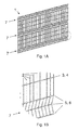
- Fig. 1 shows a perspective view ( A ) of a particular embodiment of a fence panel (1) as described herein, and a detail thereof ( B ).
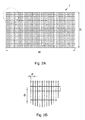
- Fig. 2 shows a front view ( A ) of the same panel (1) and a detail thereof ( B ).
- the fence panel (1) comprises a plurality of vertical wires (2) which are sandwiched between pairs of opposing horizontal wires (3,4; 5,6). Each of the vertical wires (2) is provided with three corrugations, thereby forming three horizontal beams (7).
- the distance a between adjacent vertical wires (2) is uniform along the entire width of the fence panel (1), and is about 50 mm.
- the distance between adjacent pairs of horizontal wires depends on whether the wires are provided on a beam (7) or not. Pairs of horizontal wires (3, 4) which are provided on the portions between two beams (7) are positioned at intervals b of about 200 mm from the adjacent pair of horizontal wires; whereas the distance between the pairs of horizontal wires which are provided on the beams (7) is smaller (about 107 mm).
- the vertical wires (2) and horizontal wires (3-6) have a circular transverse cross-section, wherein the diameter x of the horizontal wires (3-6) preferably is slightly larger (about 6 mm) than the diameter y of the vertical wires (2) (about 5 mm).
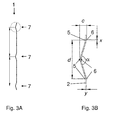
- the beams (7) have a triangular transverse cross-section, as can be seen in Fig. 3 , which is a side view ( A ) and detailed side view ( B ) of the fence panel (1) of Fig. 1 .
- the distances c and d are 37 mm and 200 mm respectively, which results in an apex angle ⁇ of about 139°. Such angle was found to provide an optimal stability of the panel (1).
- the optimal angle ⁇ may depend on the panel height.
- Each of the beams (7) is provided with three pairs of opposing horizontal wires (5, 6), more particularly one pair at each angle of the triangular beams (7). Also the vertical wire (2) portions between the beams (7) are provided with pairs of opposing horizontal wires (3, 4).
- the presence of the beams (7) and the fact that the horizontal wires (3,4; 5,6) are present as pairs of opposing wires results in a high rigidity and stability of the fence panel, even if the width of the panel is larger than the conventional panel width of 250 cm. Indeed, the inventors have found that if the panels described herein have a width w of 350 cm, they still provide a rigidity and stability compared to the much shorter conventional panels.
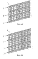
- the height h of the fence panel (1) can be varied according to the needs of the customer, and may for example vary from 150 cm to 250 cm. For heights h above 200 cm, it is preferred to provide four horizontal beams (7), as shown in Fig. 4A and 4B . For these panels, the V-shaped beams (7) are provided with an apex angle ⁇ of about 149°.
- the increased width of the panels allows for a significant reduction of fence posts required for assembling a fence. More particularly, panels having a width of 350 cm require about 28% less fence posts compared to panels having a standard width of 250 cm.
- the reduction of the number of fence posts results in a reduced amount of materials needed for building a fence (posts, post caps, clips, concrete for stabilizing posts, etc.), but also means that the assembly time can be reduced.
Landscapes
- Engineering & Computer Science (AREA)
- Architecture (AREA)
- Mechanical Engineering (AREA)
- Civil Engineering (AREA)
- Structural Engineering (AREA)
- Fencing (AREA)
Priority Applications (1)
| Application Number | Priority Date | Filing Date | Title |
|---|---|---|---|
| EP14161734.0A EP2923779A1 (de) | 2014-03-26 | 2014-03-26 | Zaunpaneel |
Applications Claiming Priority (1)
| Application Number | Priority Date | Filing Date | Title |
|---|---|---|---|
| EP14161734.0A EP2923779A1 (de) | 2014-03-26 | 2014-03-26 | Zaunpaneel |
Publications (1)
| Publication Number | Publication Date |
|---|---|
| EP2923779A1 true EP2923779A1 (de) | 2015-09-30 |
Family
ID=50439163
Family Applications (1)
| Application Number | Title | Priority Date | Filing Date |
|---|---|---|---|
| EP14161734.0A Withdrawn EP2923779A1 (de) | 2014-03-26 | 2014-03-26 | Zaunpaneel |
Country Status (1)
| Country | Link |
|---|---|
| EP (1) | EP2923779A1 (de) |
Cited By (2)
| Publication number | Priority date | Publication date | Assignee | Title |
|---|---|---|---|---|
| PL126482U1 (pl) * | 2017-07-14 | 2019-01-28 | Pyłko Andrzej Agis | Ogrodzenia |
| EP3483361B1 (de) * | 2017-11-10 | 2021-08-11 | Sncf Reseau | Gitter und sicherheitseinzäunung, die ein solches gitter umfasst |
Citations (3)
| Publication number | Priority date | Publication date | Assignee | Title |
|---|---|---|---|---|
| FR2800116A1 (fr) * | 1999-10-25 | 2001-04-27 | Michel Willoquaux | Dispositif de fixation d'un panneau en treillis sur un poteau et paroi pourvue du dispositif de fixation |
| DE10356220A1 (de) * | 2003-12-02 | 2005-07-14 | Projekt W Systeme Aus Stahl Gmbh | Sicherungseinrichtung für befahrbare oder begehbare Flächen |
| NL1027161C2 (nl) * | 2004-10-01 | 2006-04-04 | Jacobus Lambertus V Merksteijn | Hekwerk. |
-
2014
- 2014-03-26 EP EP14161734.0A patent/EP2923779A1/de not_active Withdrawn
Patent Citations (3)
| Publication number | Priority date | Publication date | Assignee | Title |
|---|---|---|---|---|
| FR2800116A1 (fr) * | 1999-10-25 | 2001-04-27 | Michel Willoquaux | Dispositif de fixation d'un panneau en treillis sur un poteau et paroi pourvue du dispositif de fixation |
| DE10356220A1 (de) * | 2003-12-02 | 2005-07-14 | Projekt W Systeme Aus Stahl Gmbh | Sicherungseinrichtung für befahrbare oder begehbare Flächen |
| NL1027161C2 (nl) * | 2004-10-01 | 2006-04-04 | Jacobus Lambertus V Merksteijn | Hekwerk. |
Cited By (2)
| Publication number | Priority date | Publication date | Assignee | Title |
|---|---|---|---|---|
| PL126482U1 (pl) * | 2017-07-14 | 2019-01-28 | Pyłko Andrzej Agis | Ogrodzenia |
| EP3483361B1 (de) * | 2017-11-10 | 2021-08-11 | Sncf Reseau | Gitter und sicherheitseinzäunung, die ein solches gitter umfasst |
Similar Documents
| Publication | Publication Date | Title |
|---|---|---|
| EP3123577B1 (de) | Kabelträger und verfahren zur herstellung solch eines kabelträgers | |
| KR101266575B1 (ko) | 서로에 대해 평행하게 배열된 복수의 와이어들을 포함하는 스트립 제조방법 및 상기 제조방법에 따라 제조된 스트립 | |
| EP2923779A1 (de) | Zaunpaneel | |
| EP0345844A1 (de) | Geschweisstes Drahtgitter mit verformten Streckdrähten und Verfahren zu seiner Herstellung | |
| TW201344015A (zh) | 鋼筋組合體、鋼筋混凝土構造體、鋼筋及剪斷補強筋 | |
| WO2015154103A1 (en) | Fencing panel | |
| KR20140111427A (ko) | 그레이팅 | |
| CN1860275A (zh) | 安全网板 | |
| EP3139430A1 (de) | Batteriegitter mit nichtplanaren teilen | |
| EP2543894A1 (de) | Verfahren zur Herstellung eines Verbindungselementes für rohrförmige Elemente zur Erstellung einer Struktur und entsprechendes Verbindungselement | |
| KR101283016B1 (ko) | 거치대의 제조방법 | |
| JP6144509B2 (ja) | メッシュパネル及びフェンス | |
| KR101283020B1 (ko) | 거치대의 제조방법 | |
| EP2599929A1 (de) | Asymmetrischer Gitterunterzug | |
| KR20150114380A (ko) | 결속구 | |
| RU155284U1 (ru) | Кронштейн забора | |
| TWI599415B (zh) | Mesh pieces, fences and wire | |
| WO2008122059A2 (en) | Fence panel | |
| KR101528292B1 (ko) | 샌드위치 패널의 벤딩구조 및 샌드위치 패널의 벤딩방법 | |
| EP2604768A1 (de) | Fachwerk | |
| RU69895U1 (ru) | Поперечный потолочный профиль | |
| CN207406118U (zh) | 滑桩以及围栏 | |
| JP2017001082A (ja) | 異形線条材の製造装置及び製造方法並びに組立体 | |
| AU2016222415B2 (en) | Post | |
| JP2013146745A (ja) | エキスパンドメタルおよびその製造方法並びにエキスパンドメタルを用いた有孔壁 |
Legal Events
| Date | Code | Title | Description |
|---|---|---|---|
| PUAI | Public reference made under article 153(3) epc to a published international application that has entered the european phase |
Free format text: ORIGINAL CODE: 0009012 |
|
| AK | Designated contracting states |
Kind code of ref document: A1 Designated state(s): AL AT BE BG CH CY CZ DE DK EE ES FI FR GB GR HR HU IE IS IT LI LT LU LV MC MK MT NL NO PL PT RO RS SE SI SK SM TR |
|
| AX | Request for extension of the european patent |
Extension state: BA ME |
|
| STAA | Information on the status of an ep patent application or granted ep patent |
Free format text: STATUS: THE APPLICATION IS DEEMED TO BE WITHDRAWN |
|
| 18D | Application deemed to be withdrawn |
Effective date: 20160331 |