EP2923936B1 - Ensemble à débit variable pour un système de freinage pour bicyclette - Google Patents
Ensemble à débit variable pour un système de freinage pour bicyclette Download PDFInfo
- Publication number
- EP2923936B1 EP2923936B1 EP15000829.0A EP15000829A EP2923936B1 EP 2923936 B1 EP2923936 B1 EP 2923936B1 EP 15000829 A EP15000829 A EP 15000829A EP 2923936 B1 EP2923936 B1 EP 2923936B1
- Authority
- EP
- European Patent Office
- Prior art keywords
- piston
- assembly
- brake assembly
- lever
- housing
- Prior art date
- Legal status (The legal status is an assumption and is not a legal conclusion. Google has not performed a legal analysis and makes no representation as to the accuracy of the status listed.)
- Active
Links
Images





Classifications
-
- B—PERFORMING OPERATIONS; TRANSPORTING
- B62—LAND VEHICLES FOR TRAVELLING OTHERWISE THAN ON RAILS
- B62L—BRAKES SPECIALLY ADAPTED FOR CYCLES
- B62L3/00—Brake-actuating mechanisms; Arrangements thereof
- B62L3/02—Brake-actuating mechanisms; Arrangements thereof for control by a hand lever
- B62L3/023—Brake-actuating mechanisms; Arrangements thereof for control by a hand lever acting on fluid pressure systems
-
- B—PERFORMING OPERATIONS; TRANSPORTING
- B62—LAND VEHICLES FOR TRAVELLING OTHERWISE THAN ON RAILS
- B62K—CYCLES; CYCLE FRAMES; CYCLE STEERING DEVICES; RIDER-OPERATED TERMINAL CONTROLS SPECIALLY ADAPTED FOR CYCLES; CYCLE AXLE SUSPENSIONS; CYCLE SIDECARS, FORECARS, OR THE LIKE
- B62K23/00—Rider-operated controls specially adapted for cycles, i.e. means for initiating control operations, e.g. levers, grips
- B62K23/02—Rider-operated controls specially adapted for cycles, i.e. means for initiating control operations, e.g. levers, grips hand actuated
- B62K23/06—Levers
-
- B—PERFORMING OPERATIONS; TRANSPORTING
- B62—LAND VEHICLES FOR TRAVELLING OTHERWISE THAN ON RAILS
- B62L—BRAKES SPECIALLY ADAPTED FOR CYCLES
- B62L3/00—Brake-actuating mechanisms; Arrangements thereof
- B62L3/02—Brake-actuating mechanisms; Arrangements thereof for control by a hand lever
- B62L3/026—Brake-actuating mechanisms; Arrangements thereof for control by a hand lever actuation by a turning handle or handlebar
Definitions
- the invention relates to a brake assembly according to the preamble of claim 1.
- a hydraulic brake system for a bicycle typically includes a hydraulic brake actuation device, a rotor attached to a wheel of the bicycle and a brake caliper operatively connected to the brake actuation device.
- the caliper is responsive to changes in hydraulic pressure generated by the brake actuation device to urge brake pads into contact with the rotor and effect braking.
- the invention satisfies the demand with the additional benefits of lighter weight and reduced manufacturing cost.
- US 4 921 081 A discloses a brake assembly for a hydraulic brake system of a bicycle with the features of the preamble of claim 1.
- the invention provides a brake assembly for a hydraulic brake system of a handlebar-steered vehicle according to claim 1.
- the invention provides linkages for a brake system, for example, in a hydraulic brake system for a bicycle.
- the invention relates to an assembly for brake actuation systems for bicycles and includes a variable rate linkage brake arrangement and lever preferably providing one or more of the following objects: 1) increased pad/brake surface gap, 2) increased end of stroke brake force, and 3) improved modulation and control, and 4) adjustability of the gap without affecting the selected variable rate of action of the linkage.
- the movement of the linkage creates a changing, i.e., variable lever blade stroke per piston actuation rate.
- This rate can be tuned to allow for greater initial fluid movement and subsequently increased pad/rotor clearance for the same lever blade stroke.
- the rate can also be tuned to have increased brake force at the end of the lever blade stroke.
- Modulation and brake control can be tuned to a desired brake force in the beginning, middle, and ending ranges of the lever blade stroke with the advantage of increased brake performance.
- Tuning the linkage also preferably provides a reduction in eccentric piston loading.
- the invention may provide a variable lever pull/master piston actuation rate for increased end-of-stroke power, variable lever pull/master piston actuation rate for reduced initial brake force, variable lever pull/master piston actuation rate for greater fluid capacity for increasing pad/rotor clearance for the same lever stroke, variable lever pull/master piston actuation rate tuned to a desired brake force in the beginning, middle, and ending ranges of the lever blade stroke with the advantage of increased brake performance.
- the invention provides reduced complexity and part count over the prior art for reduced brake system weight and reduced complexity and part count over prior art for reduced manufacturing cost.
- the invention provides a mechanism for adjusting the dead band of the lever without affecting the desired variable lever piston actuation rate by changing the rest position of the piston.
- the invention provides a brake assembly for a hydraulic brake system of a handlebar-steered vehicle, the brake assembly including a housing mountable to a handlebar of the vehicle and having a fluid chamber formed therein.
- a piston assembly is received and axially guided within the fluid chamber.
- a lever is pivotally attached to the housing.
- a cam link is provided on the lever.
- a follower link is pivotally attached to the housing, wherein movement of the lever moves the cam link and the follower link, wherein the cam and follower links interact to produce a variable rate of travel of the piston assembly relative to the travel of the lever and a pushrod is disposed between the follower link and the piston assembly.
- the follower link may have a first end that is pivotally disposed about a housing pivot and the pushrod is threadably attached to the follower link on a second end.
- the cam link may include a cam surface.
- the follower link may include a roller positioned to contact the cam surface.
- the follower link may have a first end that is pivotally disposed about a housing pivot and the pushrod is threadably attached to the follower link on a second end.
- the roller may be positioned between the first and second ends of the follower link.
- the piston assembly may include a piston disposed in a bore of the housing.
- the fluid chamber may be defined by the wall of the bore and the piston.
- the piston assembly may include a cap member positioned between the pushrod and the piston.
- the cap member may include an interior into which the pushrod keys, the pushrod rotationally fixed to the cap member.
- the cap member may abut the piston at an end portion thereof, the cap member end portion including a flange.
- the assembly may further include a piston adjustment mechanism disposed in the housing, the piston adjustment mechanism including a manually movable member positioned about and keyed to the piston assembly, wherein the movable member moves axially to adjust a rest position of the piston assembly in the bore without affecting the variable rate of travel of the piston.
- the manually movable member may be manually rotatable and moves axially when rotated.
- the piston assembly may include a cap member that abuts a piston at an end portion thereof, the cap member end portion including a flange.
- the movable member of the position adjustment mechanism may contact the flange of the cap member and wherein adjustment of the position of the movable member in the housing causes adjustment of the rest position of the piston assembly.
- the movable member may be threadably engaged with the housing.
- the pushrod may be threadably engaged to the follower link.
- the pushrod may be keyed to the piston assembly wherein a thread pitch of the movable member to the housing matches a thread pitch of the pushrod in the follower link such that when the piston assembly position is adjusted by rotation and axial movement of the position adjustment mechanism the pushrod is moved an equal amount in the same direction to retain contact with the piston assembly.
- the piston adjustment mechanism may include a detent mechanism disposed in the housing that acts on the movable member of the piston adjustment mechanism.
- the detent mechanism may be a ball detent.
- the piston adjustment mechanism may include a manually operated dial keyed to the rotatable member and the ball detent acts upon a non-round exterior of the dial of the piston adjustment mechanism.
- the cam link may be formed as a single piece with the lever or may be pivotally attached to the lever.
- a brake assembly which according to an embodiment may be constructed or arranged to operate an otherwise conventional hydraulic brake system (not shown).
- the invention provides a brake assembly and system constructed to produce a desired variable lever ratio, i.e., one that is non-linear, which will be described in detail hereinbelow.
- the invention contemplates the provision of a mechanism to adjust the dead band in the assembly without affecting the desired non-linear nature of the brake assembly.
- the inventive brake assembly may be used on any type of hand operated brake for bicycles, motorcycles, three and four-wheelers, for example.
- For bicycles variations are possible for road style brake levers, different styles of mountain bike brake levers, or BMX brake levers. Other applications could include hydraulic clutch systems.
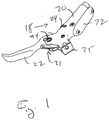
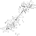
- the brake assembly 18 includes a housing 20.
- the brake assembly 18 includes a lever 22 pivotally attached to the housing 20.
- the lever 22 may include a lever adjustment mechanism 38.
- the housing 20 includes a bore 24.
- a piston assembly 28 is reciprocally disposed within the bore 24.
- the bore 24 includes a fluid chamber 26.
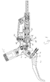
- a linkage 21 operates between the lever 22 and the piston assembly 28 to produce a variable rate of travel of the piston assembly.
- An optional piston adjustment mechanism 40 operates between the linkage 21 and the piston assembly 28 to adjust the amount of dead band in the system without affecting the operation of the linkage 21.
- a clamp device 25 or any suitable fastening means may be part of or attached to the housing 20 for attaching the housing to a handlebar of a bicycle (not shown), for example.
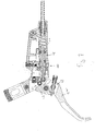
- Fig. 9 shows the brake assembly of Figs. 1-8 and is an embodiment that omits the piston adjustment mechanism.
- the lever 22 may be in the form of a blade pivotally attached to the housing 20 of the brake assembly 18 by a first pin or pivot 34.
- a cam or cam-shaped link 42 which is part of one embodiment of the linkage 21, is either formed as part of the lever 22 or pivotally disposed on the first pin 34.
- the cam 42 has a cam-shaped surface 44 along one portion 46.
- a lever adjusting mechanism 38 may be adjusttably attached to the lever 22 on a second pin or pivot 36, with the second pin attached to the lever.
- the second pin 36 may be generally outboard from the first pin 34.
- the lever adjusting mechanism 38 may include a threaded shaft 47 threadably engaged with the second pin 36.
- One end of the lever adjusting mechanism 38 includes a grasping part 48 that is accessible and manipulatable by a user and the other end of the lever adjusting mechanism 38 includes a flared end or stop 50.
- the stop 50 abuts the cam 42 at the end 52 generally opposite the cam surface 44. Twisting the grasping part 48 causes the shaft 47 to either be inserted farther or removed from its engagement with the second pin 36, and as a result change the distance between the second pin 36 and the adjustment end of the cam 52. In this manner, the orientation of the cam 42 on the lever 22 can be changed, and the position of the lever is altered relative to a handlebar (not shown) when mounted thereon or the housing 20.
- the linkage 21 also includes a follower 54.
- the follower 54 is pivotally disposed on the housing 20.
- the follower 54 may be disposed on a third pin or pivot 56 attached to the housing 20.
- the follower 54 includes a fourth pin 60, which is located opposite the third pin 56.
- the fourth pin 60 may include a threaded bore 62.
- the follower 54 may include a roller 58, which is rotatably disposed between the third pin 56 and the fourth pin 60.
- the roller 58 engages the cam surface 44 of the cam link.
- the interaction of the follower 54 and the cam 42 when the lever 22 is moved causes the piston assembly 28 to travel according to the profile of the cam surface 44.
- the position of the roller 58 on the cam surface 44 determines the part of the profile of the cam surface actuating the piston assembly 28 in response to movement of the lever 22.
- the follower 54 may be secured to the third pin 56 with a locknut 68.
- the housing 20 may be any suitable shape that can define a hollow interior including a bore 24, and accommodates the mounting of and operation of the linkage 21.
- the housing 20 may be made of any suitable material, for example, metal, plastic, composite materials or combinations thereof.
- the bore 24 includes a fluid chamber 26.
- the fluid chamber 26 includes brake fluid as is known.
- the illustrated brake assembly 18 is known as an "open" type of fluid system.
- the assembly 18 includes a “backpack” reservoir 100.
- the backpack reservoir 100 includes a reservoir chamber 102 defined in a portion of the housing 20 in communication with the fluid chamber 26. Extending through the bore wall 33 between the reservoir chamber 102 is a timing port 104 and a compensating port 106.
- a diaphragm or seal 70 made of an elastomeric material such as silicon rubber is made to cover the reservoir chamber 102.
- the basic operation of the brake assembly 18 is well understood by those skilled in the art. Pivoting the lever 22 from a rest position causes the piston assembly 28 to drive the piston into the bore 24. As the piston inwardly, the cup or umbrella seal 31 covers the timing port 104 which pressurizes the fluid within the hydraulic line 110 at the end of the fluid chamber 26 and which in turn actuates a slave cylinder within a hydraulically coupled brake caliper (not shown). When the lever 22 is released, the compression spring 64 biases the piston 30 toward the first end of the fluid chamber 26 to reassume the rest or home position.
- the distance between the cup seal 31 and the timing port 104 is referred to as the "dead-band.”
- the cup seal 31 is between the timing port 104 and the first end of the fluid chamber 26
- fluid in the reservoir 102 between the seal 31 and the timing port 104 returns to the reservoir 102, perhaps causing expansion of the diaphragm 70.
- the second end of the fluid chamber 26 cannot be pressurized. It is highly desirable to be able to adjust the length of the dead-band in accordance with user preferences.
- a piston assembly 28 is disposed in the bore 24 and fluid chamber 26.
- the piston assembly 28 may include a piston 30 positioned at one end thereof, e.g., at or near a distal end 27 of the assembly, which piston may be provided with one or more seal 31.
- the seal 31 sealingly engages the wall 33 of the bore 24 at predetermined positions within the fluid chamber 26 and reciprocates therein.
- the seal 31 may be one or more O-rings, for example, or umbrella seals, for example. Where two seals 31 are used, the rearmost 31A of the two seals (31A, 31B) may be considered to define with the piston 30 and the wall 33 of the bore 24 the fluid chamber 26, i.e., the volume of the bore that includes fluid.
- the piston assembly 28 is constructed and positioned within the bore 24 to reciprocate along a piston assembly axis 32.
- the piston assembly 28 is preferably biased in a rest or home position by a piston assembly biasing element 64, which may be a spring, such as a coil spring as shown.
- the action of the biasing element 64 may also return the lever 22 to a rest or home position.
- the piston assembly 28 may include a separate cap member 74.
- the cap member 74 may be a barrel shaped piece that fits within the bore 24 and abuts the proximal end of the piston 30.
- the cap member 74 includes a flange 76 or the like at or near the end abutting the piston.
- the cap member 74 may also include a non-round interior 78 that may in the form of a key hole or the like.
- a pushrod 80 is connected to the follower 54 at one end and contacts the piston assembly 28 at the other end.
- the pushrod 80 includes a head 82.
- the head 82 includes a ball surface received in a corresponding interior 78 of the cap member 74 of the piston assembly 28 in a keyed relationship.
- the pushrod 80 may be threaded engaged with a threaded bore 62 of the fourth pin 60 at an end opposite the head 82.
- the piston assembly 28 can be a single-piece as shown or formed as multiple pieces.
- the piston 30 may be a separate part of the assembly 28.
- the piston 30 may be formed as a single-piece construction with the cap member 74.
- the linkage 21 is operated by movement of the lever 22, which in turn causes the piston assembly 28 to move and generate fluid pressure within the fluid chamber 26.
- the linkage 21 includes a cam link member 42 attached to the lever 22 and a follower link member 54 attached to the housing 20.
- the fluid chamber 26 will be connected to a remote slave cylinder (not shown) which operates the hydraulic brake system through a hydraulic line to effect the application of fluid pressure on a brake component such as a disc brake or the like in a known manner.
- the brake assembly may include a piston adjustment mechanism 40 that is disposed in the housing 20.
- the piston adjustment mechanism 40 includes a sleeve member 86 that is disposed about and keyed to the cap member 74.
- the sleeve member 86 is also threadably engaged in the bore 24 of the housing 20.
- the sleeve member 84 may be turned by a manually movable member 84 that is keyed to the sleeve member.
- the movable member 84 when rotated, causes axial movement of the sleeve member 86 and movement of the sleeve member causes axial movement of the cap member 74 through interaction of the sleeve member with the flange 76 of the cap member.
- the pushrod 80 is translated axially the same amount and in the same direction as the cap member 74 by the threaded engagement of the pushrod in the fourth pin 60. In this way, no slack or lash is created by adjustment of the dead band with the piston adjustment mechanism 40. Also, the positions of the elements of the linkage 21 are unaffected.
- a biasing spring 120 ( Fig. 2 ) is positioned between the lever blade 22 and the lever body housing 20. This spring 120 applies a torsional load between the lever 22 and the housing 20. The purpose is to maintain the components of the brake and adjustment mechanisms in contact with each other. Without spring 120, the components would be loose inside the lever and housing 20.
- a ball detent mechanism 88 disposed in the housing 20 may be used to retain the dial 84 in position.
- the ball detent mechanism 88 includes a ball 92 urged against the dial 84 by a spring 94.
- the ball detent mechanism 88 is held in the housing 20 by a screw 96 or the like.
- the dial 84 may have exterior features 90 formed on the outside thereof that interacts with the ball 92 to resist unintended rotation thereof.
- the elements of the linkage 21 creates a variable or changing lever blade stroke relative to the piston actuation rate.
- this rate can be tuned to be initially higher than a conventional linear brake system and then, near the end of the lever blade stroke tuned to be at or lower than the rate of a conventional brake system.
- the variable rate linkage of the invention thus yields increased brake performance in accordance with a number of braking aspects.
- a benefit to the changing or variable rate system according to embodiments of the invention is a decreased initial brake/surface force that increases as the lever is further actuated.
- a brake system can thus be tuned to have less initial "bite” upon first contact of the pads to the brake surface, have moderate brake force through the mid-stroke, and then have the maximum brake force at higher user hand forces. This allows for greater control and predictability by the user. Also, the dead band of the system can be adjusted by the user without affecting the operation, performance and feel of the brake rate provided by the linkage according to the invention.
Landscapes
- Engineering & Computer Science (AREA)
- Mechanical Engineering (AREA)
- Physics & Mathematics (AREA)
- Fluid Mechanics (AREA)
- Transmission Of Braking Force In Braking Systems (AREA)
- Braking Arrangements (AREA)
Claims (16)
- Ensemble (18) de freinage pour un système de freinage hydraulique d'un véhicule piloté par guidon, l'ensemble (18) de freinage comprenant :un logement (20) montable sur un guidon du véhicule et ayant une chambre (26) pour fluide formée dans celui-ci ;un ensemble (28) de piston reçu et axialement guidé à l'intérieur de la chambre (26) pour fluide ;un levier (22) fixé pivotant au logement (20) ;une liaison (42) par came sur le levier (22), dans lequel la liaison (42) par came inclut une surface (44) de came ;une liaison suiveuse (54) fixée pivotante au logement (20), dans lequel un mouvement du levier (22) déplace la liaison (42) par came et la liaison suiveuse (54),dans lequel les liaisons par came et suiveuse (42, 54) interagissent pour produire un taux variable de déplacement de l'ensemble (28) de piston par rapport au déplacement du levier (22) ; etune tige-poussoir (80) disposée entre la liaison suiveuse (54) et l'ensemble (28) de piston, caractérisé en ce quela liaison suiveuse (54) inclut un galet (58) positionné pour contacter la surface (44) de came, et en ce que la liaison suiveuse (54) a une première extrémité qui est disposée pivotante autour d'un pivot (56) de logement et la tige-poussoir (80) est fixée par filetage à la liaison suiveuse (54) sur une deuxième extrémité.
- Ensemble (18) de freinage selon la revendication 1, dans lequel le levier (22) et la liaison (42) par came pivotent tous les deux sur un pivot commun.
- Ensemble (18) de freinage selon la revendication 1 ou 2, dans lequel le galet est positionné entre les première et deuxième extrémités de la liaison suiveuse.
- Ensemble (18) de freinage selon l'une des revendications précédentes, dans lequel l'ensemble (28) de piston inclut un piston disposé dans un alésage du logement.
- Ensemble (18) de freinage selon la revendication 4, dans lequel la chambre (26) pour fluide est définie par la paroi de l'alésage et le piston.
- Ensemble (18) de freinage selon la revendication 4, dans lequel l'ensemble (28) de piston inclut un élément obturateur positionné entre la tige-poussoir (80) et le piston.
- Ensemble (18) de freinage selon la revendication 6, dans lequel l'élément obturateur inclut un intérieur dans lequel la tige-poussoir (80) se clavète, la tige-poussoir (80) fixée rotative à l'élément obturateur.
- Ensemble (18) de freinage selon la revendication 6, dans lequel l'élément obturateur bute contre le piston au niveau d'une partie d'extrémité de celui-ci, la partie d'extrémité d'élément obturateur incluant un rebord.
- Ensemble (18) de freinage selon l'une des revendications précédentes, comprenant en outre : un mécanisme d'ajustement de piston disposé dans le logement, le mécanisme d'ajustement de piston incluant un élément mobile manuellement positionné autour de et claveté sur l'ensemble de piston, dans lequel l'élément mobile se déplace axialement pour ajuster une position de repos de l'ensemble (28) de piston dans l'alésage sans affecter le taux variable de déplacement du piston.
- Ensemble (18) de freinage selon la revendication 9, dans lequel l'élément mobile manuellement est rotatif manuellement et se déplace axialement lorsqu'il est tourné.
- Ensemble (18) de freinage selon les revendications 8 et 9 ou les revendications 8 et 10, dans lequel l'élément mobile du mécanisme d'ajustement de piston contacte le rebord de l'élément obturateur et dans lequel l'ajustement de la position de l'élément mobile dans le logement (20) cause l'ajustement de la position de repos de l'ensemble de piston.
- Ensemble (18) de freinage selon la revendication 11, dans lequel l'élément mobile est engagé par filetage avec le logement.
- Ensemble (18) de freinage selon les revendications 7 et 12, dans lequel un pas de filetage de l'élément mobile sur le logement (20) correspond à un pas de filetage de la tige-poussoir (80) dans la liaison suiveuse (54) de telle manière que, lorsque la position d'ensemble (28) de piston est ajustée par une rotation et un mouvement axial du mécanisme d'ajustement de piston, la tige-poussoir (80) est déplacée d'une quantité égale dans le même sens pour maintenir le contact avec l'ensemble de piston.
- Ensemble (18) de freinage selon la revendication 9, dans lequel le mécanisme d'ajustement de piston inclut un mécanisme de détente disposé dans le logement (20) qui agit sur l'élément mobile du mécanisme d'ajustement de piston, dans lequel en particulier le mécanisme de détente est une détente à bille.
- Ensemble (18) de freinage selon la revendication 14, dans lequel le mécanisme d'ajustement de piston inclut un cadran opéré manuellement claveté sur l'élément rotatif et la détente à bille agit sur un extérieur non rond du cadran du mécanisme d'ajustement de piston.
- Ensemble (18) de freinage selon l'une des revendications précédentes, dans lequel la liaison (42) par came est formée comme une seule pièce avec le levier, ou dans lequel la liaison (42) par came est fixée pivotante au levier.
Applications Claiming Priority (1)
| Application Number | Priority Date | Filing Date | Title |
|---|---|---|---|
| US14/223,846 US9290232B2 (en) | 2014-03-24 | 2014-03-24 | Variable rate assembly for a brake system for bicycle |
Publications (2)
| Publication Number | Publication Date |
|---|---|
| EP2923936A1 EP2923936A1 (fr) | 2015-09-30 |
| EP2923936B1 true EP2923936B1 (fr) | 2019-10-16 |
Family
ID=53008231
Family Applications (1)
| Application Number | Title | Priority Date | Filing Date |
|---|---|---|---|
| EP15000829.0A Active EP2923936B1 (fr) | 2014-03-24 | 2015-03-20 | Ensemble à débit variable pour un système de freinage pour bicyclette |
Country Status (5)
| Country | Link |
|---|---|
| US (1) | US9290232B2 (fr) |
| EP (1) | EP2923936B1 (fr) |
| CN (1) | CN104943804B (fr) |
| DE (1) | DE102015003658A1 (fr) |
| TW (1) | TWI582005B (fr) |
Families Citing this family (21)
| Publication number | Priority date | Publication date | Assignee | Title |
|---|---|---|---|---|
| US10550858B2 (en) * | 2014-08-25 | 2020-02-04 | Shimano Inc. | Bicycle control device |
| US10046829B2 (en) * | 2015-03-06 | 2018-08-14 | Shimano Inc. | Bicycle hydraulic operating device |
| US10501144B2 (en) * | 2015-11-05 | 2019-12-10 | Sram, Llc | Bicycle lever assembly adjustment device |
| US9963192B2 (en) * | 2016-02-01 | 2018-05-08 | Shimano Inc. | Non-metallic bracket for a bicycle hydraulic component |
| US10167044B2 (en) * | 2016-02-01 | 2019-01-01 | Shimano Inc. | Non-metallic bracket |
| US10240619B2 (en) | 2016-02-04 | 2019-03-26 | Shimano Inc. | Bicycle operating device |
| US9937978B2 (en) | 2016-06-15 | 2018-04-10 | Shimano Inc. | Bicycle hydraulic operating device |
| US10232905B2 (en) | 2016-06-15 | 2019-03-19 | Shimano Inc. | Bicycle hydraulic operating device |
| DE102017206712A1 (de) | 2016-06-16 | 2017-12-21 | Shimano Inc. | Hydraulische Fahrrad-Betätigungsvorrichtung |
| US10300983B2 (en) * | 2017-08-03 | 2019-05-28 | Shimano Inc. | Operating assembly |
| DE102017219666A1 (de) * | 2017-11-06 | 2019-05-09 | Gustav Magenwirth Gmbh & Co. Kg | Hydraulikgebervorrichtung für eine hydraulische Bremse oder Kupplung lenkergeführter Fahrzeuge und hydraulische Bremse eines lenkergeführten Fahrzeuges |
| US11124263B2 (en) * | 2018-07-06 | 2021-09-21 | Hayes Bicycle Group Inc. | Brake system |
| US12221082B2 (en) * | 2019-06-05 | 2025-02-11 | Andrew James Perry | Brake master cylinder |
| DE102019215772A1 (de) * | 2019-10-14 | 2021-04-15 | Shimano Inc. | Hydraulische Betätigungsvorrichtung |
| US11572128B2 (en) * | 2020-05-19 | 2023-02-07 | Shimano Inc. | Piston assembly for human-powered vehicle |
| US12024260B2 (en) * | 2020-07-23 | 2024-07-02 | Hayes Bicycle Group Inc. | Brake assembly |
| US11945544B2 (en) | 2022-02-17 | 2024-04-02 | Sram, Llc | Control device for a bicycle |
| DE102022103695A1 (de) * | 2022-02-17 | 2023-08-17 | Shimano Inc. | Betätigungsvorrichtung für ein muskelkraftbetriebenes fahrzeug |
| DE102022112565A1 (de) | 2022-05-19 | 2023-11-23 | Shimano Inc. | Betätigungsvorrichtung für ein muskelkraftbetriebenes fahrzeug |
| DE102022121163A1 (de) * | 2022-08-22 | 2024-02-22 | Trickstuff Gmbh | Hydraulische Bremsanordnung für ein wenigstens teilweise muskelbetriebenes Fahrrad |
| TWM650641U (zh) * | 2023-03-22 | 2024-01-21 | 大陸商蘭溪市捷克運動器材製造有限公司 | 一種摩擦塊平行度可調的制動組件 |
Citations (2)
| Publication number | Priority date | Publication date | Assignee | Title |
|---|---|---|---|---|
| US2346758A (en) * | 1941-03-07 | 1944-04-18 | Gen Motors Corp | Brake |
| US4921081A (en) * | 1988-12-22 | 1990-05-01 | Autra-Bike Co., Inc. | Hydraulic brake apparatus for bicycles |
Family Cites Families (17)
| Publication number | Priority date | Publication date | Assignee | Title |
|---|---|---|---|---|
| US4560049A (en) | 1982-09-28 | 1985-12-24 | Honda Giken Kogyo Kabushiki Kaisha | Operation device for clutch master cylinder with means to adjust the play stroke of the clutch lever |
| GB8421830D0 (en) | 1984-08-29 | 1984-10-03 | Automotive Prod Plc | Hydraulic master cylinder |
| US4865164A (en) | 1988-12-15 | 1989-09-12 | Mitsuharu Kaneda | Positive shut-off power assisted brakes |
| JPH041034Y2 (fr) | 1989-09-13 | 1992-01-14 | Nissin Kogyo Kk | |
| JPH10230886A (ja) | 1997-02-20 | 1998-09-02 | Nissin Kogyo Kk | バーハンドル車両用液圧マスタシリンダの操作レバー |
| US20030121736A1 (en) * | 2001-12-28 | 2003-07-03 | Avid, L.L.C. | Master cylinder lever for a hydraulic disc brake having a backpack reservoir |
| DE60314975T2 (de) | 2002-12-27 | 2008-04-10 | Nissin Kogyo Co. Ltd., Ueda | Hydraulischer Steuerzylinder für ein Fahrzeug mit Lenker |
| EP1723030A1 (fr) | 2004-03-09 | 2006-11-22 | Hayes Bicycle Group, Inc. | Ensemble levier et maitre-cylindre |
| WO2007128058A1 (fr) | 2006-05-08 | 2007-11-15 | Owen Hutchison | Came profilée pour assister un levier |
| US7487638B2 (en) | 2006-06-09 | 2009-02-10 | Shimano Inc. | Bicycle hydraulic brake accentuate device |
| US7757821B2 (en) * | 2006-06-09 | 2010-07-20 | Shimano Inc. | Bicycle hydraulic brake actuation device |
| US8336308B2 (en) * | 2006-11-06 | 2012-12-25 | Freni Brembo S.P.A. | Lever device for operating a hydraulic actuator, particularly for motorcycles |
| CN201179939Y (zh) * | 2008-01-30 | 2009-01-14 | 陈瑞斌 | 螺锁结合的碟刹把手装置 |
| US9840304B2 (en) * | 2011-03-03 | 2017-12-12 | Shimano Inc. | Hydraulic brake actuation device |
| EP2699469A2 (fr) * | 2011-04-19 | 2014-02-26 | Gustav Magenwirth GmbH & Co. KG | Transmetteur pour élément d'actionnement hydraulique |
| US8393449B2 (en) * | 2011-07-07 | 2013-03-12 | Sram, Llc | Variable rate linkage for a brake system for a handlebar-steered vehicle |
| DE202014100854U1 (de) * | 2014-02-25 | 2014-06-05 | Shimano Inc. | Fahrrad-Betätigungsvorrichtung |
-
2014
- 2014-03-24 US US14/223,846 patent/US9290232B2/en active Active
-
2015
- 2015-03-20 TW TW104109002A patent/TWI582005B/zh active
- 2015-03-20 EP EP15000829.0A patent/EP2923936B1/fr active Active
- 2015-03-20 DE DE102015003658.0A patent/DE102015003658A1/de active Pending
- 2015-03-24 CN CN201510131716.XA patent/CN104943804B/zh active Active
Patent Citations (2)
| Publication number | Priority date | Publication date | Assignee | Title |
|---|---|---|---|---|
| US2346758A (en) * | 1941-03-07 | 1944-04-18 | Gen Motors Corp | Brake |
| US4921081A (en) * | 1988-12-22 | 1990-05-01 | Autra-Bike Co., Inc. | Hydraulic brake apparatus for bicycles |
Also Published As
| Publication number | Publication date |
|---|---|
| TW201540597A (zh) | 2015-11-01 |
| TWI582005B (zh) | 2017-05-11 |
| DE102015003658A1 (de) | 2015-09-24 |
| EP2923936A1 (fr) | 2015-09-30 |
| CN104943804B (zh) | 2017-12-08 |
| US9290232B2 (en) | 2016-03-22 |
| US20150266540A1 (en) | 2015-09-24 |
| CN104943804A (zh) | 2015-09-30 |
Similar Documents
| Publication | Publication Date | Title |
|---|---|---|
| US9290232B2 (en) | Variable rate assembly for a brake system for bicycle | |
| EP2543585B1 (fr) | Liaison à débit variable pour système de freinage d'un véhicule à guidon directeur | |
| JP6466944B2 (ja) | 自転車用油圧二重制御装置 | |
| US11319017B2 (en) | Hydraulic brake control device with staggered timing ports | |
| EP1514791B1 (fr) | Dispositif de commande de freins hydrauliques pour bicyclettes, motocyclettes et véhicules similaires | |
| EP3535168B1 (fr) | Système de levier | |
| EP3018049B1 (fr) | Dispositif de commande de frein hydraulique pour un guidon de bicyclette | |
| JP4254336B2 (ja) | ブレーキ装置のストロークシミュレータ | |
| US20150083531A1 (en) | Brake system | |
| US20250196964A1 (en) | Hydraulic brake control unit and handlebar assembly | |
| US20220185426A1 (en) | Hydraulic brake control device with handlebar proximal hose attachment | |
| US12097927B2 (en) | Hydraulic brake control device with handlebar proximal hose attachment | |
| EP2086825B1 (fr) | Dispositif de levier pour faire fonctionner un actionneur hydraulique, en particulier pour motocyclettes | |
| US20120124991A1 (en) | Method and apparatus for lever stroke adjustment | |
| US20150135881A1 (en) | Integrated drive for bicycle handlebars | |
| JP6630214B2 (ja) | 減衰力調整装置および油圧緩衝器 |
Legal Events
| Date | Code | Title | Description |
|---|---|---|---|
| PUAI | Public reference made under article 153(3) epc to a published international application that has entered the european phase |
Free format text: ORIGINAL CODE: 0009012 |
|
| AK | Designated contracting states |
Kind code of ref document: A1 Designated state(s): AL AT BE BG CH CY CZ DE DK EE ES FI FR GB GR HR HU IE IS IT LI LT LU LV MC MK MT NL NO PL PT RO RS SE SI SK SM TR |
|
| AX | Request for extension of the european patent |
Extension state: BA ME |
|
| 17P | Request for examination filed |
Effective date: 20160329 |
|
| RBV | Designated contracting states (corrected) |
Designated state(s): AL AT BE BG CH CY CZ DE DK EE ES FI FR GB GR HR HU IE IS IT LI LT LU LV MC MK MT NL NO PL PT RO RS SE SI SK SM TR |
|
| 17Q | First examination report despatched |
Effective date: 20160509 |
|
| STAA | Information on the status of an ep patent application or granted ep patent |
Free format text: STATUS: EXAMINATION IS IN PROGRESS |
|
| GRAP | Despatch of communication of intention to grant a patent |
Free format text: ORIGINAL CODE: EPIDOSNIGR1 |
|
| STAA | Information on the status of an ep patent application or granted ep patent |
Free format text: STATUS: GRANT OF PATENT IS INTENDED |
|
| INTG | Intention to grant announced |
Effective date: 20190508 |
|
| GRAS | Grant fee paid |
Free format text: ORIGINAL CODE: EPIDOSNIGR3 |
|
| GRAA | (expected) grant |
Free format text: ORIGINAL CODE: 0009210 |
|
| STAA | Information on the status of an ep patent application or granted ep patent |
Free format text: STATUS: THE PATENT HAS BEEN GRANTED |
|
| RAP1 | Party data changed (applicant data changed or rights of an application transferred) |
Owner name: SRAM, LLC |
|
| AK | Designated contracting states |
Kind code of ref document: B1 Designated state(s): AL AT BE BG CH CY CZ DE DK EE ES FI FR GB GR HR HU IE IS IT LI LT LU LV MC MK MT NL NO PL PT RO RS SE SI SK SM TR |
|
| RAP1 | Party data changed (applicant data changed or rights of an application transferred) |
Owner name: SRAM, LLC |
|
| REG | Reference to a national code |
Ref country code: GB Ref legal event code: FG4D |
|
| REG | Reference to a national code |
Ref country code: CH Ref legal event code: EP |
|
| REG | Reference to a national code |
Ref country code: DE Ref legal event code: R096 Ref document number: 602015039761 Country of ref document: DE |
|
| REG | Reference to a national code |
Ref country code: IE Ref legal event code: FG4D |
|
| REG | Reference to a national code |
Ref country code: AT Ref legal event code: REF Ref document number: 1191000 Country of ref document: AT Kind code of ref document: T Effective date: 20191115 |
|
| REG | Reference to a national code |
Ref country code: NL Ref legal event code: FP |
|
| REG | Reference to a national code |
Ref country code: LT Ref legal event code: MG4D |
|
| REG | Reference to a national code |
Ref country code: AT Ref legal event code: MK05 Ref document number: 1191000 Country of ref document: AT Kind code of ref document: T Effective date: 20191016 |
|
| PG25 | Lapsed in a contracting state [announced via postgrant information from national office to epo] |
Ref country code: LT Free format text: LAPSE BECAUSE OF FAILURE TO SUBMIT A TRANSLATION OF THE DESCRIPTION OR TO PAY THE FEE WITHIN THE PRESCRIBED TIME-LIMIT Effective date: 20191016 Ref country code: SE Free format text: LAPSE BECAUSE OF FAILURE TO SUBMIT A TRANSLATION OF THE DESCRIPTION OR TO PAY THE FEE WITHIN THE PRESCRIBED TIME-LIMIT Effective date: 20191016 Ref country code: LV Free format text: LAPSE BECAUSE OF FAILURE TO SUBMIT A TRANSLATION OF THE DESCRIPTION OR TO PAY THE FEE WITHIN THE PRESCRIBED TIME-LIMIT Effective date: 20191016 Ref country code: BG Free format text: LAPSE BECAUSE OF FAILURE TO SUBMIT A TRANSLATION OF THE DESCRIPTION OR TO PAY THE FEE WITHIN THE PRESCRIBED TIME-LIMIT Effective date: 20200116 Ref country code: FI Free format text: LAPSE BECAUSE OF FAILURE TO SUBMIT A TRANSLATION OF THE DESCRIPTION OR TO PAY THE FEE WITHIN THE PRESCRIBED TIME-LIMIT Effective date: 20191016 Ref country code: PT Free format text: LAPSE BECAUSE OF FAILURE TO SUBMIT A TRANSLATION OF THE DESCRIPTION OR TO PAY THE FEE WITHIN THE PRESCRIBED TIME-LIMIT Effective date: 20200217 Ref country code: AT Free format text: LAPSE BECAUSE OF FAILURE TO SUBMIT A TRANSLATION OF THE DESCRIPTION OR TO PAY THE FEE WITHIN THE PRESCRIBED TIME-LIMIT Effective date: 20191016 Ref country code: ES Free format text: LAPSE BECAUSE OF FAILURE TO SUBMIT A TRANSLATION OF THE DESCRIPTION OR TO PAY THE FEE WITHIN THE PRESCRIBED TIME-LIMIT Effective date: 20191016 Ref country code: NO Free format text: LAPSE BECAUSE OF FAILURE TO SUBMIT A TRANSLATION OF THE DESCRIPTION OR TO PAY THE FEE WITHIN THE PRESCRIBED TIME-LIMIT Effective date: 20200116 Ref country code: GR Free format text: LAPSE BECAUSE OF FAILURE TO SUBMIT A TRANSLATION OF THE DESCRIPTION OR TO PAY THE FEE WITHIN THE PRESCRIBED TIME-LIMIT Effective date: 20200117 Ref country code: PL Free format text: LAPSE BECAUSE OF FAILURE TO SUBMIT A TRANSLATION OF THE DESCRIPTION OR TO PAY THE FEE WITHIN THE PRESCRIBED TIME-LIMIT Effective date: 20191016 |
|
| PG25 | Lapsed in a contracting state [announced via postgrant information from national office to epo] |
Ref country code: RS Free format text: LAPSE BECAUSE OF FAILURE TO SUBMIT A TRANSLATION OF THE DESCRIPTION OR TO PAY THE FEE WITHIN THE PRESCRIBED TIME-LIMIT Effective date: 20191016 Ref country code: HR Free format text: LAPSE BECAUSE OF FAILURE TO SUBMIT A TRANSLATION OF THE DESCRIPTION OR TO PAY THE FEE WITHIN THE PRESCRIBED TIME-LIMIT Effective date: 20191016 Ref country code: IS Free format text: LAPSE BECAUSE OF FAILURE TO SUBMIT A TRANSLATION OF THE DESCRIPTION OR TO PAY THE FEE WITHIN THE PRESCRIBED TIME-LIMIT Effective date: 20200224 |
|
| PG25 | Lapsed in a contracting state [announced via postgrant information from national office to epo] |
Ref country code: AL Free format text: LAPSE BECAUSE OF FAILURE TO SUBMIT A TRANSLATION OF THE DESCRIPTION OR TO PAY THE FEE WITHIN THE PRESCRIBED TIME-LIMIT Effective date: 20191016 |
|
| REG | Reference to a national code |
Ref country code: DE Ref legal event code: R097 Ref document number: 602015039761 Country of ref document: DE |
|
| PG2D | Information on lapse in contracting state deleted |
Ref country code: IS |
|
| PG25 | Lapsed in a contracting state [announced via postgrant information from national office to epo] |
Ref country code: RO Free format text: LAPSE BECAUSE OF FAILURE TO SUBMIT A TRANSLATION OF THE DESCRIPTION OR TO PAY THE FEE WITHIN THE PRESCRIBED TIME-LIMIT Effective date: 20191016 Ref country code: CZ Free format text: LAPSE BECAUSE OF FAILURE TO SUBMIT A TRANSLATION OF THE DESCRIPTION OR TO PAY THE FEE WITHIN THE PRESCRIBED TIME-LIMIT Effective date: 20191016 Ref country code: EE Free format text: LAPSE BECAUSE OF FAILURE TO SUBMIT A TRANSLATION OF THE DESCRIPTION OR TO PAY THE FEE WITHIN THE PRESCRIBED TIME-LIMIT Effective date: 20191016 Ref country code: DK Free format text: LAPSE BECAUSE OF FAILURE TO SUBMIT A TRANSLATION OF THE DESCRIPTION OR TO PAY THE FEE WITHIN THE PRESCRIBED TIME-LIMIT Effective date: 20191016 Ref country code: IS Free format text: LAPSE BECAUSE OF FAILURE TO SUBMIT A TRANSLATION OF THE DESCRIPTION OR TO PAY THE FEE WITHIN THE PRESCRIBED TIME-LIMIT Effective date: 20200216 |
|
| PLBE | No opposition filed within time limit |
Free format text: ORIGINAL CODE: 0009261 |
|
| STAA | Information on the status of an ep patent application or granted ep patent |
Free format text: STATUS: NO OPPOSITION FILED WITHIN TIME LIMIT |
|
| PG25 | Lapsed in a contracting state [announced via postgrant information from national office to epo] |
Ref country code: SK Free format text: LAPSE BECAUSE OF FAILURE TO SUBMIT A TRANSLATION OF THE DESCRIPTION OR TO PAY THE FEE WITHIN THE PRESCRIBED TIME-LIMIT Effective date: 20191016 Ref country code: SM Free format text: LAPSE BECAUSE OF FAILURE TO SUBMIT A TRANSLATION OF THE DESCRIPTION OR TO PAY THE FEE WITHIN THE PRESCRIBED TIME-LIMIT Effective date: 20191016 Ref country code: IT Free format text: LAPSE BECAUSE OF FAILURE TO SUBMIT A TRANSLATION OF THE DESCRIPTION OR TO PAY THE FEE WITHIN THE PRESCRIBED TIME-LIMIT Effective date: 20191016 |
|
| 26N | No opposition filed |
Effective date: 20200717 |
|
| PG25 | Lapsed in a contracting state [announced via postgrant information from national office to epo] |
Ref country code: MC Free format text: LAPSE BECAUSE OF FAILURE TO SUBMIT A TRANSLATION OF THE DESCRIPTION OR TO PAY THE FEE WITHIN THE PRESCRIBED TIME-LIMIT Effective date: 20191016 |
|
| REG | Reference to a national code |
Ref country code: CH Ref legal event code: PL |
|
| PG25 | Lapsed in a contracting state [announced via postgrant information from national office to epo] |
Ref country code: SI Free format text: LAPSE BECAUSE OF FAILURE TO SUBMIT A TRANSLATION OF THE DESCRIPTION OR TO PAY THE FEE WITHIN THE PRESCRIBED TIME-LIMIT Effective date: 20191016 |
|
| REG | Reference to a national code |
Ref country code: BE Ref legal event code: MM Effective date: 20200331 |
|
| PG25 | Lapsed in a contracting state [announced via postgrant information from national office to epo] |
Ref country code: LU Free format text: LAPSE BECAUSE OF NON-PAYMENT OF DUE FEES Effective date: 20200320 |
|
| PG25 | Lapsed in a contracting state [announced via postgrant information from national office to epo] |
Ref country code: LI Free format text: LAPSE BECAUSE OF NON-PAYMENT OF DUE FEES Effective date: 20200331 Ref country code: CH Free format text: LAPSE BECAUSE OF NON-PAYMENT OF DUE FEES Effective date: 20200331 Ref country code: IE Free format text: LAPSE BECAUSE OF NON-PAYMENT OF DUE FEES Effective date: 20200320 |
|
| PG25 | Lapsed in a contracting state [announced via postgrant information from national office to epo] |
Ref country code: BE Free format text: LAPSE BECAUSE OF NON-PAYMENT OF DUE FEES Effective date: 20200331 |
|
| GBPC | Gb: european patent ceased through non-payment of renewal fee |
Effective date: 20200320 |
|
| PG25 | Lapsed in a contracting state [announced via postgrant information from national office to epo] |
Ref country code: GB Free format text: LAPSE BECAUSE OF NON-PAYMENT OF DUE FEES Effective date: 20200320 |
|
| REG | Reference to a national code |
Ref country code: DE Ref legal event code: R082 Ref document number: 602015039761 Country of ref document: DE Representative=s name: THUM, MOETSCH, WEICKERT PATENTANWAELTE PARTG M, DE Ref country code: DE Ref legal event code: R082 Ref document number: 602015039761 Country of ref document: DE Representative=s name: THUM & PARTNER THUM MOETSCH WEICKERT PATENTANW, DE |
|
| PG25 | Lapsed in a contracting state [announced via postgrant information from national office to epo] |
Ref country code: TR Free format text: LAPSE BECAUSE OF FAILURE TO SUBMIT A TRANSLATION OF THE DESCRIPTION OR TO PAY THE FEE WITHIN THE PRESCRIBED TIME-LIMIT Effective date: 20191016 Ref country code: MT Free format text: LAPSE BECAUSE OF FAILURE TO SUBMIT A TRANSLATION OF THE DESCRIPTION OR TO PAY THE FEE WITHIN THE PRESCRIBED TIME-LIMIT Effective date: 20191016 Ref country code: CY Free format text: LAPSE BECAUSE OF FAILURE TO SUBMIT A TRANSLATION OF THE DESCRIPTION OR TO PAY THE FEE WITHIN THE PRESCRIBED TIME-LIMIT Effective date: 20191016 |
|
| PGFP | Annual fee paid to national office [announced via postgrant information from national office to epo] |
Ref country code: NL Payment date: 20220217 Year of fee payment: 8 Ref country code: FR Payment date: 20220218 Year of fee payment: 8 |
|
| PG25 | Lapsed in a contracting state [announced via postgrant information from national office to epo] |
Ref country code: MK Free format text: LAPSE BECAUSE OF FAILURE TO SUBMIT A TRANSLATION OF THE DESCRIPTION OR TO PAY THE FEE WITHIN THE PRESCRIBED TIME-LIMIT Effective date: 20191016 |
|
| P01 | Opt-out of the competence of the unified patent court (upc) registered |
Effective date: 20230524 |
|
| REG | Reference to a national code |
Ref country code: NL Ref legal event code: MM Effective date: 20230401 |
|
| PG25 | Lapsed in a contracting state [announced via postgrant information from national office to epo] |
Ref country code: NL Free format text: LAPSE BECAUSE OF NON-PAYMENT OF DUE FEES Effective date: 20230401 |
|
| PG25 | Lapsed in a contracting state [announced via postgrant information from national office to epo] |
Ref country code: FR Free format text: LAPSE BECAUSE OF NON-PAYMENT OF DUE FEES Effective date: 20230331 |
|
| PGFP | Annual fee paid to national office [announced via postgrant information from national office to epo] |
Ref country code: DE Payment date: 20260213 Year of fee payment: 12 |