EP2923977A1 - Procédé de séparation d'une pile partielle à partir d'une pile totale et de transfert de cette pile partielle jusqu'à une table vibrante - Google Patents
Procédé de séparation d'une pile partielle à partir d'une pile totale et de transfert de cette pile partielle jusqu'à une table vibrante Download PDFInfo
- Publication number
- EP2923977A1 EP2923977A1 EP14161294.5A EP14161294A EP2923977A1 EP 2923977 A1 EP2923977 A1 EP 2923977A1 EP 14161294 A EP14161294 A EP 14161294A EP 2923977 A1 EP2923977 A1 EP 2923977A1
- Authority
- EP
- European Patent Office
- Prior art keywords
- stack
- sub
- gripper device
- vibrating table
- gripper
- Prior art date
- Legal status (The legal status is an assumption and is not a legal conclusion. Google has not performed a legal analysis and makes no representation as to the accuracy of the status listed.)
- Granted
Links
Images




Classifications
-
- B—PERFORMING OPERATIONS; TRANSPORTING
- B65—CONVEYING; PACKING; STORING; HANDLING THIN OR FILAMENTARY MATERIAL
- B65H—HANDLING THIN OR FILAMENTARY MATERIAL, e.g. SHEETS, WEBS, CABLES
- B65H3/00—Separating articles from piles
- B65H3/32—Separating articles from piles by elements, e.g. fingers, plates, rollers, inserted or traversed between articles to be separated and remainder of the pile
- B65H3/322—Separating articles from piles by elements, e.g. fingers, plates, rollers, inserted or traversed between articles to be separated and remainder of the pile for separating a part of the pile, i.e. several articles at once
-
- B—PERFORMING OPERATIONS; TRANSPORTING
- B65—CONVEYING; PACKING; STORING; HANDLING THIN OR FILAMENTARY MATERIAL
- B65H—HANDLING THIN OR FILAMENTARY MATERIAL, e.g. SHEETS, WEBS, CABLES
- B65H5/00—Feeding articles separated from piles; Feeding articles to machines
- B65H5/08—Feeding articles separated from piles; Feeding articles to machines by grippers, e.g. suction grippers
- B65H5/10—Reciprocating or oscillating grippers, e.g. suction or gripper tables
-
- B—PERFORMING OPERATIONS; TRANSPORTING
- B65—CONVEYING; PACKING; STORING; HANDLING THIN OR FILAMENTARY MATERIAL
- B65H—HANDLING THIN OR FILAMENTARY MATERIAL, e.g. SHEETS, WEBS, CABLES
- B65H5/00—Feeding articles separated from piles; Feeding articles to machines
- B65H5/08—Feeding articles separated from piles; Feeding articles to machines by grippers, e.g. suction grippers
- B65H5/14—Details of grippers; Actuating-mechanisms therefor
-
- B—PERFORMING OPERATIONS; TRANSPORTING
- B65—CONVEYING; PACKING; STORING; HANDLING THIN OR FILAMENTARY MATERIAL
- B65H—HANDLING THIN OR FILAMENTARY MATERIAL, e.g. SHEETS, WEBS, CABLES
- B65H2301/00—Handling processes for sheets or webs
- B65H2301/40—Type of handling process
- B65H2301/42—Piling, depiling, handling piles
- B65H2301/422—Handling piles, sets or stacks of articles
- B65H2301/4224—Gripping piles, sets or stacks of articles
- B65H2301/42242—Gripping piles, sets or stacks of articles by acting on the outermost articles of the pile for clamping the pile
-
- B—PERFORMING OPERATIONS; TRANSPORTING
- B65—CONVEYING; PACKING; STORING; HANDLING THIN OR FILAMENTARY MATERIAL
- B65H—HANDLING THIN OR FILAMENTARY MATERIAL, e.g. SHEETS, WEBS, CABLES
- B65H2301/00—Handling processes for sheets or webs
- B65H2301/40—Type of handling process
- B65H2301/42—Piling, depiling, handling piles
- B65H2301/422—Handling piles, sets or stacks of articles
- B65H2301/4228—Dividing piles
-
- B—PERFORMING OPERATIONS; TRANSPORTING
- B65—CONVEYING; PACKING; STORING; HANDLING THIN OR FILAMENTARY MATERIAL
- B65H—HANDLING THIN OR FILAMENTARY MATERIAL, e.g. SHEETS, WEBS, CABLES
- B65H2407/00—Means not provided for in groups B65H2220/00 – B65H2406/00 specially adapted for particular purposes
- B65H2407/20—Means not provided for in groups B65H2220/00 – B65H2406/00 specially adapted for particular purposes for manual intervention of operator
-
- B—PERFORMING OPERATIONS; TRANSPORTING
- B65—CONVEYING; PACKING; STORING; HANDLING THIN OR FILAMENTARY MATERIAL
- B65H—HANDLING THIN OR FILAMENTARY MATERIAL, e.g. SHEETS, WEBS, CABLES
- B65H2551/00—Means for control to be used by operator; User interfaces
- B65H2551/10—Command input means
- B65H2551/16—Levers; Joysticks
-
- B—PERFORMING OPERATIONS; TRANSPORTING
- B65—CONVEYING; PACKING; STORING; HANDLING THIN OR FILAMENTARY MATERIAL
- B65H—HANDLING THIN OR FILAMENTARY MATERIAL, e.g. SHEETS, WEBS, CABLES
- B65H2701/00—Handled material; Storage means
- B65H2701/10—Handled articles or webs
- B65H2701/11—Dimensional aspect of article or web
- B65H2701/113—Size
- B65H2701/1131—Size of sheets
- B65H2701/11312—Size of sheets large formats, i.e. above A3
Definitions
- the invention relates to a method for separating an upper part of a stack of stack-shaped Good formed cuboid overall stack and for transferring this sub-stack of the remaining residual stack to a vibrating table.
- the operator grips the entire stack in the area of the side facing the vibrating table and with one hand separates an upper part stack from the remaining stack.
- the operator pulls the partial stack taken slightly from the rest of the stack and attacks the partial stack with the other hand at the opposite end of the sub-stack.
- the small-format partial stack is then pulled by the operator over the remaining stack to the vibrating table and stored there on the vibrating table or a stack already lying on the vibrating table. Subsequently, the shaking of lying on the vibrating table sheet layers.
- a fully automatic loading device for stack formed from sheet-shaped Good said device having a gripper device is in the EP 2 418 163 A1 described.
- Object of the present invention is to provide a method for separating an upper part of a stack of stack-shaped Good stacked stack and for transferring this sub-stack of the remaining stack to a vibrating table so that with little structural effort a simple removal of a large-sized sub-stack of a Total stack for transferring the sub-stack is possible to Studttel ancient times.
- the invention proposes a method having the features of claim 1.
- the separation of the partial stack from the total stack and the transfer of the sub-stack to the vibrating table thus take place partially automatically or partially manually.
- the separation of the sub-stack from the remaining stack in the area facing the vibrating table is done manually, whereby a device for carrying out the method can be achieved with significantly less construction effort.
- the separation of the separate area of this sub-stack on the gripper device is done manually, so that it is only necessary to perform the actual gripping process and the actual process of the sub-stack for vibrating table by machine.
- the opening of the gripper device and the depositing of the sub-stack on the vibrating table are also carried out by machine, furthermore the retraction of the gripper device into the area of the remainder stack so that the process sequence according to the invention can be connected once or several times to remove a new upper sub-stack from the remaining total stack Transfer this sub-stack to the vibrating table.
- the feature of depositing the sub-stack on the vibrating table is to be understood in such a way that the sub-stack is not placed directly on the table surface of the vibrating table. This only applies to the first partial stack to be deposited on the vibrating table. Since a vibrating table is usually loaded with several sub-stacks, and only then the final shaking of the sheet layers, the second sub-stack is placed on the resting already on the vibrating stack, the third stack on the already resting on the vibrating table layer of the first and second partial stack stored, etc.
- the method steps E. and F. in particular the method steps E., F. and G. occur fully automatically. As a result, this process is more automated.
- a method that is automated to a lesser extent is provided according to a second preferred alternative.
- the repelling of the sub-stack of advantage whereby the repelled portion of the sub-stack rests on the remaining portion of the sub-stack, because of the sub-stack in this Position does not have to be taken by the operator and they can operate the gripper device instead.
- This stick operating element is in particular configured in such a way that when the stick operating element is swiveled away by the operator of the stick operating element, the gripper device is raised and the gripper device is lowered when the stick operating element is pivoted toward the operator, or when the stick operating element is swiveled the gripper device is lowered by the operator of the stick operating element and the gripper device is raised when the stick operating element is swiveled toward the operator.
- the respective alternative is adjustable by means of an adjusting element, so that the operator can choose the more pleasant mode.
- the stick-control element is designed such that when a pivoting of the stick-control element in the direction of the vibrating table, the gripper device moves in the direction of the vibrating table, while at a pivoting of the stick-control element away from the vibrating table, the gripper device moves away from the vibrating table, thus backtracked to the total pile.
- the gripper device is moved at a higher speed.
- the method of the gripper device is understood to mean not only the method of the gripper device in the direction of the vibrating table or away from it, but also the movement of the lifting and lowering of the gripper device.
- the gripper device is operated manually and in this case grasped by the operator by means of one hand, the operator can grasp and track the end of the sub-stack facing away from the gripper device with the other hand when moving the partial stack to the vibrating table.
- This tracking is understood in particular to mean a slight lifting of the sub-stack by means of the other hand, so that the sub-stack can be pulled away without adversely affecting the remaining stack below by means of the gripper device and, moreover, transferred to the depositing position without adversely affecting the vibrating table and on the vibrating table can be stored.
- a partial stack of leafy material is grasped and transferred by means of the method, which consists of cardboard or cardboard.
- the sub-stack is supported by a base between the remaining stack and the vibrating table when transferring from the remaining stack to the vibrating table.
- the partial stack can thus not bend down into a gap between the remaining stack and the vibrating table.
- the partial stack is supported by rolling in said area. This support or rolling supports can be effected by means of a plurality of juxtaposed support elements or support rollers, so that the partial stack is pulled over these multiple support elements or support rollers.
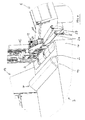
- the Fig. 1 and 6 show a device 1 for removing an upper part of a stack 2 of a sheet-shaped Good formed total stack 3 and for transferring this sub-stack 2 of the remaining stack 4 to a vibrating table 5.
- the device 1 has a gripper device 6 for gripping the sub-stack 2 in one of the remaining stack 4 off-hook area 7 (see Fig. 5 ) on which the vibrating table 5 side facing between two gripper lower parts 8 and two deliverable with respect to these gripper lower parts 8 gripper upper parts 9 (see Fig. 3 ) on.
- the gripper device 6 can be raised and lowered by means of displacement means 10 and mounted reciprocably in a frame 11 between the total stack 3 and the vibrating table 5.
- the device 1 further comprises an actuating device 12 for manually actuating the gripper device 6 and for manually actuating the displacement means 10, wherein the actuating device 12 is movable together with the gripper device 6.
- a first stationary frame part 13 of the frame 11 receives a second frame part 14 of the frame 11 horizontally displaceable and it is this second Frame part 14 by means of a first, part of the displacement means 10 forming adjusting means 15 with respect to the first frame member 13 slidably.
- the second frame part 14 receives a third frame part 16 of the frame 11 in a vertically displaceable manner.
- This third frame part 16 is displaceable relative to the first frame part 14 by means of a second actuating means 17 forming part of the displacement means 10.
- the gripper device 6 is mounted.
- the actuating device 12 is likewise mounted in the third frame part 16. When lifting and lowering the gripper device 6 thus the actuator 12 is raised or lowered accordingly.
- the actuating device 12 moves accordingly. If the gripper device 6 is opposite, thus moved by the vibrating table 5 to the total stack 3, the actuator 12 moves accordingly.
- a stacker 19 rests, which carries a total stack 3. With progressive removal of partial stacks 2 from the remaining stack 4, the respective residual stack 4 is raised by the stacking pin 19, so that an approximately constant height level of the gripper device 6 results in removing the respective sub-stack 2, whereby the respective sub-stack 2 of this higher level substantially in one horizontal movement can be pulled on the next to the total stack 3 placed vibrating table 5.
- the vibrating table 5 is also on the floor 18.
- the vibrating table 5 is formed in the usual manner. It has a base frame 20 which rests on the floor 18. This base frame 20 receives tiltably a table part 21, the table surface of the recording of the sub-stack 2 is used and can be tilted from a horizontal plane about two spatial axes, in particular in the Fig. 1 shown inclined position. In this position, the partial stack 2 is located on a first, perpendicular to the table part 21 arranged ruler 22 and arranged perpendicular to this ruler 22, also perpendicular to the table part 21 arranged ruler 23 at.
- the ruler 23, which is arranged on the side facing the overall stack 3, can be pivotably mounted about a ruler 23 associated narrow side, as to the pivot axis 24 according to Fig. 5 clarified.
- This possibility of pivoting of the ruler 23 with respect to the table part 21 basically allows this ruler 23 to be arranged in a plane to the table part 21, so that a partial stack 2 can be transferred to the vibrating table 5, without the need, the sub-stack 2 on the vertical ruler 23 have to lead over.
- a freely rotatable roller 25 arranged in the region of the free end of the ruler 23 and parallel to this end, which is mounted in the ruler 23, contributes to the partial stack 22 being able to be transferred to the table part 21 of the vibrating table 5 in a rolling manner , Between the total stack 3 and the vibrating table 5, the device 1 further rollers 26, 27, which contribute to the partial stack 2 rolling, thus supported by the rollers 25 to 27 can be moved from the remaining stack 4 to the vibrating table 5.
- the vibrating table 5 facing the end of the sub-stack 2 is gripped by means of the gripper device 6.
- the stick operating element 28 is pivotable in the direction of the vibrating table 8 and away from the vibrating table 8 in two opposite directions A, B for moving the gripper device 6. If the stick control element 28 is pivoted in the direction A, the gripper device 6 moves, in concrete terms, the second frame part 14 together with the gripper device 6 in the direction of the vibrating table 5. If the stick operating element 28 is pivoted in the opposite direction B, the arrangement moves from the second Frame part 14 and gripper device 6 in the opposite direction.
- the stick operating element 28 for raising and lowering the gripper device 6 in opposite directions C, D is pivotable. If the stick control element 28 is pivoted in direction C, this causes a lowering Conversely, moving the stick-operating element 28 in the opposite direction C leads to an opposite movement, thus lifting the gripper device 6.
- the directions A and B are thus perpendicular to the gripper device 6, specifically a lowering of the third frame member 16 and gripper means the directions C and D arranged.
- the stick-control element 28 is driven such that with increasing deflection of the stick-control element from a neutral position, a method of the gripper device 6 is carried out at a higher speed.
- buttons 29 and 30 are provided on the side facing away from the operator of the stick-control element 28.
- this is provided with a switching strip 31.
- the operator grasps with one hand, preferably the right hand, the stick control element 28 and presses down the switching strip 31, which is a deadman switch. If the operator does not act on the switching strip 31, the function of the actuating device 12 is switched off. By pivoting the stick-control element 28 in the directions A, B, C, D, the described different movements can be brought about.
- the gripper device 6 Upon actuation of the button 29, while still embraces stick-control element 28 by means of a finger, the gripper device 6 is activated, thus closed or opened. If, instead, the key 30 is actuated, the gripper device 6 is activated with additional blown air instead.
- the actuating device 12 further comprises a arranged in the console 22 button 37, which causes when activated, the gripper device 6 automatically moves after placing the partial stack 2 on the vibrating table 5 in the starting position adjacent to the remaining stack 4. It is thus not necessary to perform this return movement by pressing the stick control element 28 by the operator.
- the Fig. 2 and 3 illustrate in detail the structure and the arrangement of the gripper device 6. It is illustrated that the respective gripper upper part 9 is pivotally mounted about a horizontal axis 38 in a receptacle 39 of the gripper device 6 and by means of adjusting means 40 about this axis 38 from a substantially vertical Fishgreifwolf ( Fig. 2 ) into a gripping position ( Fig. 3 ) are pivotable.
- the gripper upper part 9 is arranged horizontally in the gripping position with a then lower gripping surface 41.
- the gripper lower part 8 has an upper gripping surface 42, which is arranged horizontally. In a free region of the gripper lower part 8, this air nozzle 43 has to output the blast air.
- a support segment 44 is arranged between the two gripper lower parts 8. Further, on the side facing away from the support segment 44 of the gripper lower parts 8 supporting segments 45 and 46 are arranged. Here, the upper surfaces of the support segments 44 to 46 form a plane with the gripping surfaces 42 of the gripper lower parts 8, so that a partial stack 2 to be transferred rests completely on the support segments 44 to 46.
- the support members 45 and 46 in contact with the vibrating table 5 to Axes 47 can pivot freely upwards, moreover, the support segment 46 is mounted in the piece segment 45.
- the gripper device 6 or the third frame part 16 with sensor means, in particular a height sensor, for detecting the position of the gripper device 6 relative to the vibrating table or a stack already resting on the vibrating table 5.
- sensor means in particular a height sensor, for detecting the position of the gripper device 6 relative to the vibrating table or a stack already resting on the vibrating table 5.
- sensor means enable a more automated approach of the vibrating table 5 or of the stack resting thereon, possibly even a fully automatic starting of the vibrating table 5.
- the separation of the upper part of the stack 2 of the formed from the sheet-shaped Good cuboid total stack 3 and for transferring the part of the stack 2 from the remaining remaining stack 4 to the vibrating table 5 is preferably as follows:
- Fig. 4 Based on the state according to Fig. 1 first, as in Fig. 4 illustrated, the partial stack 2 in the vibrating table 5 facing area 7 manually separated from the remaining stack 4, wherein the partial stack 2 is repelled in this area on the adjacent area 49 of the sub-stack 2. Subsequently, by operating the stick operating element 28 in the direction C, the gripper device 6 is moved into the area 7 exposed by the separation of the sub-stack 2 above the remaining stack 4 and the gripper lower parts 8 are positioned adjacent to the upper surface of the residual stack 4. This condition is also in Fig. 4 shown. Then the manual repelling of the separate area 7 of the sub-stack 2 with open gripper device 6 on the gripper base 8. This is followed by the clamping of the deposited on the gripper lower part 8 portion of the sub-stack 2 between the two gripper lower parts 8 and the two associated gripper upper parts 9 connects.
- This condition is in Fig. 5 shown.
- the gripper device 6 engages the partial stack 2 for the vibrating table 5.
- the gripper device is initially slightly obliquely upward and then, to store the sub-stack 2 on the vibrating table 5, slightly downward to move. Accordingly, the operator performs an individual movement of the stick control element 28, which is composed of a superposition of a movement in the directions D and A and then A and C until finally the gripper device 6 has arrived in the region of the vibrating table 5 facing away from the total stack 3
- the partial stack 2 can be stored there by opening the gripper device 6.
- the retraction of the gripper device 6 to the starting position, to take over a next partial stack 2 is effected either by actuating the stick control element 28 initially in the direction A and then in the directions B, D and C, wherein this movement when pressing the button 27 can also be done automatically, since the transfer position of the sub-stack 2 is preferably unchanged due to the height adjustment of the remaining stack 4 by means of the stacking pin 19.
- the method of the gripping device gripping the partial stack for the vibrating table, the opening of the gripper device with depositing of the partial stack on the vibrating table and the retraction of the gripper device into the region of the remaining stack can also be carried out fully automatically. It is thus not necessary to operate the stick control element after gripping the sub-stack by means of the gripper device, but it is sufficient to actuate an additionally existing automatic button, which is arranged in particular in the region of the console. In this case, the operator has both hands free during the process of sub-stack 2, so that they can then grasp the partial stack at the end 28 with both hands and handle it there.
- large-format partial stacks can be handled with the device. These are in particular formats between 700 mm x 1000 mm and 1000 mm x 1400 mm.
- the leafy estate consists in particular of cardboard or cardboard.
- the reference numeral 50 is in Fig. 6 a stack formed of a plurality of stored stacks 2 on the vibrating table 5 formed stack.
Landscapes
- Engineering & Computer Science (AREA)
- Mechanical Engineering (AREA)
- Sheets, Magazines, And Separation Thereof (AREA)
- Pile Receivers (AREA)
Priority Applications (1)
| Application Number | Priority Date | Filing Date | Title |
|---|---|---|---|
| EP14161294.5A EP2923977B1 (fr) | 2014-03-24 | 2014-03-24 | Procédé de séparation d'une pile partielle à partir d'une pile totale et de transfert de cette pile partielle jusqu'à une table vibrante |
Applications Claiming Priority (1)
| Application Number | Priority Date | Filing Date | Title |
|---|---|---|---|
| EP14161294.5A EP2923977B1 (fr) | 2014-03-24 | 2014-03-24 | Procédé de séparation d'une pile partielle à partir d'une pile totale et de transfert de cette pile partielle jusqu'à une table vibrante |
Publications (2)
| Publication Number | Publication Date |
|---|---|
| EP2923977A1 true EP2923977A1 (fr) | 2015-09-30 |
| EP2923977B1 EP2923977B1 (fr) | 2016-07-20 |
Family
ID=50343687
Family Applications (1)
| Application Number | Title | Priority Date | Filing Date |
|---|---|---|---|
| EP14161294.5A Active EP2923977B1 (fr) | 2014-03-24 | 2014-03-24 | Procédé de séparation d'une pile partielle à partir d'une pile totale et de transfert de cette pile partielle jusqu'à une table vibrante |
Country Status (1)
| Country | Link |
|---|---|
| EP (1) | EP2923977B1 (fr) |
Cited By (1)
| Publication number | Priority date | Publication date | Assignee | Title |
|---|---|---|---|---|
| CN106586651A (zh) * | 2017-02-14 | 2017-04-26 | 陈荣辉 | 一种智能接片机 |
Families Citing this family (4)
| Publication number | Priority date | Publication date | Assignee | Title |
|---|---|---|---|---|
| DE102019116301A1 (de) | 2019-06-14 | 2020-12-17 | Koenig & Bauer Ag | Substrathandhabungssystem und Verfahren zum Betreiben eines Substrathandhabungssystems |
| DE102019116304A1 (de) * | 2019-06-14 | 2020-12-17 | Koenig & Bauer Ag | Substrathandhabungssystem und Verfahren zum Betreiben eines Substrathandhabungssystems |
| DE102019116302A1 (de) * | 2019-06-14 | 2020-12-17 | Koenig & Bauer Ag | Substrathandhabungssystem und Verfahren zum Betreiben eines Substrathandhabungssystems |
| DE102019116306B4 (de) * | 2019-06-14 | 2026-04-02 | Koenig & Bauer Ag | Substrathandhabungssystem und Verfahren zum Betreiben eines Substrathandhabungssystems |
Citations (5)
| Publication number | Priority date | Publication date | Assignee | Title |
|---|---|---|---|---|
| US3176859A (en) * | 1961-06-27 | 1965-04-06 | Beloit Eastern Corp | Stack divider |
| US3206042A (en) * | 1963-04-17 | 1965-09-14 | Peterson Eric Ronald | Multiple sheet handling device |
| DE2649959C2 (de) | 1976-10-30 | 1985-09-12 | Karl Mohr | Vorrichtung zur Übergabe eines Teilstapels zu beschneidenden Gutes von einem Gesamtstapel in eine Rüttelstation |
| EP1593627A2 (fr) * | 2004-05-05 | 2005-11-09 | Baumann Maschinenbau Solms GmbH & Co. KG | Dispositif pour automatiquement débiter des piles de matériau en feuilles, en particulier des piles de papier |
| EP2418163A1 (fr) | 2010-08-11 | 2012-02-15 | Adolf Mohr Maschinenfabrik GmbH & Co. KG | Dispositif de chargement pour piles de feuilles |
-
2014
- 2014-03-24 EP EP14161294.5A patent/EP2923977B1/fr active Active
Patent Citations (5)
| Publication number | Priority date | Publication date | Assignee | Title |
|---|---|---|---|---|
| US3176859A (en) * | 1961-06-27 | 1965-04-06 | Beloit Eastern Corp | Stack divider |
| US3206042A (en) * | 1963-04-17 | 1965-09-14 | Peterson Eric Ronald | Multiple sheet handling device |
| DE2649959C2 (de) | 1976-10-30 | 1985-09-12 | Karl Mohr | Vorrichtung zur Übergabe eines Teilstapels zu beschneidenden Gutes von einem Gesamtstapel in eine Rüttelstation |
| EP1593627A2 (fr) * | 2004-05-05 | 2005-11-09 | Baumann Maschinenbau Solms GmbH & Co. KG | Dispositif pour automatiquement débiter des piles de matériau en feuilles, en particulier des piles de papier |
| EP2418163A1 (fr) | 2010-08-11 | 2012-02-15 | Adolf Mohr Maschinenfabrik GmbH & Co. KG | Dispositif de chargement pour piles de feuilles |
Cited By (1)
| Publication number | Priority date | Publication date | Assignee | Title |
|---|---|---|---|---|
| CN106586651A (zh) * | 2017-02-14 | 2017-04-26 | 陈荣辉 | 一种智能接片机 |
Also Published As
| Publication number | Publication date |
|---|---|
| EP2923977B1 (fr) | 2016-07-20 |
Similar Documents
| Publication | Publication Date | Title |
|---|---|---|
| EP3736235B1 (fr) | Dispositif de manipulation de pile de produits pliés, plieuse correspondante, et procédé de transfert de piles de produits | |
| EP2923977B1 (fr) | Procédé de séparation d'une pile partielle à partir d'une pile totale et de transfert de cette pile partielle jusqu'à une table vibrante | |
| EP0422562B1 (fr) | Dispositif pour transporter une section de pile de feuilles d'une pile à une station de traitement ultérieur | |
| EP2923978B1 (fr) | Dispositif de prélèvement d'une pile partielle à partir d'une pile totale et de transfert de cette pile partielle jusqu'à une table vibrante | |
| EP0363722B2 (fr) | Méthode et dispositif pour le désempilage de feuilles empilées en blocs sur des palettes | |
| DE2548893A1 (de) | Entstapelgeraet zum abheben eines teilstapels von einem blaetterstapel | |
| DE2723162C2 (de) | Verfahren zum Entlüften eines auf einem Rütteltisch gerüttelten Teilstapels zu schneidenden Gutes und Vorrichtung zur Durchführung des Verfahrens | |
| DE3808651C2 (de) | Vorrichtung zum Ergreifen und Vereinzeln des unteren Zuschnittes eines Stapels von Zuschnitten aus kaschiertem Papier o. dgl., insbesondere für eine Buchdeckenmaschine | |
| EP0181993A1 (fr) | Dispositif pour saisir et déposer des produits divers | |
| EP2418163B1 (fr) | Dispositif de chargement pour piles de feuilles | |
| EP2637955A1 (fr) | Procédé pour déposer des objets en forme de feuille et système pour mettre en oeuvre ce procédé | |
| DE2914289C2 (de) | Verfahren und Vorrichtung zum Vereinzeln aufeinander gestapelter runder Deckel mit Randwulst | |
| EP2128057A1 (fr) | Procédé et dispositiv de levage et de manipulation d'une pile de feuilles ou d'une partie de celle-ci | |
| DE102022118978A1 (de) | Auslage und Verfahren zum Betreiben einer Auslage mit einem von einem Stapelhubantrieb vertikal verlagerbaren Stapelträger | |
| EP1389597B1 (fr) | Méthode et dispositif pour dépiler une pile d'articles disposés en plusieurs couches horizontales | |
| EP0751086A2 (fr) | Dispositif pour extraire les inclusions d'air de piles de papier | |
| DE3226940C1 (de) | Vorrichtung zum Vereinzeln und Abheben der obersten Platine von einem Platinenstapel | |
| EP1598293A1 (fr) | Procédé pour charger une table vibrante et dispositif pour mettre en oeuvre le procédé | |
| DE7728960U1 (de) | Vorrichtung zum aufstossen von blattmaterial-bogen zu einem stapel | |
| EP2058256B1 (fr) | Dispositif destiné à secouer un bien en forme de feuilles empilées | |
| DE3403209A1 (de) | Einrichtung zur beseitigung von lufteinschluessen aus papierstapeln | |
| DE10258896A1 (de) | Vorrichtung zum Trennen von Bogen | |
| DE3113023A1 (de) | Vorrichtung zum schichten von verschiedenartigen boegen | |
| EP1264794B1 (fr) | Méthode et dispositif pour la formation d'une pile sur un récepteur de pile | |
| DE872052C (de) | Verfahren zum Abfuehlen der Stapelhoehe an Bogen verarbeitenden Maschinen, insbesondere Druckmaschinen |
Legal Events
| Date | Code | Title | Description |
|---|---|---|---|
| PUAI | Public reference made under article 153(3) epc to a published international application that has entered the european phase |
Free format text: ORIGINAL CODE: 0009012 |
|
| 17P | Request for examination filed |
Effective date: 20141121 |
|
| AK | Designated contracting states |
Kind code of ref document: A1 Designated state(s): AL AT BE BG CH CY CZ DE DK EE ES FI FR GB GR HR HU IE IS IT LI LT LU LV MC MK MT NL NO PL PT RO RS SE SI SK SM TR |
|
| AX | Request for extension of the european patent |
Extension state: BA ME |
|
| GRAP | Despatch of communication of intention to grant a patent |
Free format text: ORIGINAL CODE: EPIDOSNIGR1 |
|
| RIC1 | Information provided on ipc code assigned before grant |
Ipc: B65H 3/32 20060101AFI20160118BHEP Ipc: B65H 5/10 20060101ALI20160118BHEP Ipc: B65H 5/14 20060101ALI20160118BHEP |
|
| INTG | Intention to grant announced |
Effective date: 20160219 |
|
| GRAS | Grant fee paid |
Free format text: ORIGINAL CODE: EPIDOSNIGR3 |
|
| GRAA | (expected) grant |
Free format text: ORIGINAL CODE: 0009210 |
|
| AK | Designated contracting states |
Kind code of ref document: B1 Designated state(s): AL AT BE BG CH CY CZ DE DK EE ES FI FR GB GR HR HU IE IS IT LI LT LU LV MC MK MT NL NO PL PT RO RS SE SI SK SM TR |
|
| REG | Reference to a national code |
Ref country code: GB Ref legal event code: FG4D Free format text: NOT ENGLISH |
|
| REG | Reference to a national code |
Ref country code: CH Ref legal event code: EP |
|
| REG | Reference to a national code |
Ref country code: IE Ref legal event code: FG4D Free format text: LANGUAGE OF EP DOCUMENT: GERMAN |
|
| REG | Reference to a national code |
Ref country code: AT Ref legal event code: REF Ref document number: 813888 Country of ref document: AT Kind code of ref document: T Effective date: 20160815 |
|
| REG | Reference to a national code |
Ref country code: DE Ref legal event code: R096 Ref document number: 502014001131 Country of ref document: DE |
|
| REG | Reference to a national code |
Ref country code: LT Ref legal event code: MG4D |
|
| REG | Reference to a national code |
Ref country code: NL Ref legal event code: MP Effective date: 20160720 |
|
| PG25 | Lapsed in a contracting state [announced via postgrant information from national office to epo] |
Ref country code: IT Free format text: LAPSE BECAUSE OF FAILURE TO SUBMIT A TRANSLATION OF THE DESCRIPTION OR TO PAY THE FEE WITHIN THE PRESCRIBED TIME-LIMIT Effective date: 20160720 Ref country code: HR Free format text: LAPSE BECAUSE OF FAILURE TO SUBMIT A TRANSLATION OF THE DESCRIPTION OR TO PAY THE FEE WITHIN THE PRESCRIBED TIME-LIMIT Effective date: 20160720 Ref country code: FI Free format text: LAPSE BECAUSE OF FAILURE TO SUBMIT A TRANSLATION OF THE DESCRIPTION OR TO PAY THE FEE WITHIN THE PRESCRIBED TIME-LIMIT Effective date: 20160720 Ref country code: NL Free format text: LAPSE BECAUSE OF FAILURE TO SUBMIT A TRANSLATION OF THE DESCRIPTION OR TO PAY THE FEE WITHIN THE PRESCRIBED TIME-LIMIT Effective date: 20160720 Ref country code: IS Free format text: LAPSE BECAUSE OF FAILURE TO SUBMIT A TRANSLATION OF THE DESCRIPTION OR TO PAY THE FEE WITHIN THE PRESCRIBED TIME-LIMIT Effective date: 20161120 Ref country code: LT Free format text: LAPSE BECAUSE OF FAILURE TO SUBMIT A TRANSLATION OF THE DESCRIPTION OR TO PAY THE FEE WITHIN THE PRESCRIBED TIME-LIMIT Effective date: 20160720 Ref country code: NO Free format text: LAPSE BECAUSE OF FAILURE TO SUBMIT A TRANSLATION OF THE DESCRIPTION OR TO PAY THE FEE WITHIN THE PRESCRIBED TIME-LIMIT Effective date: 20161020 Ref country code: RS Free format text: LAPSE BECAUSE OF FAILURE TO SUBMIT A TRANSLATION OF THE DESCRIPTION OR TO PAY THE FEE WITHIN THE PRESCRIBED TIME-LIMIT Effective date: 20160720 |
|
| PG25 | Lapsed in a contracting state [announced via postgrant information from national office to epo] |
Ref country code: GR Free format text: LAPSE BECAUSE OF FAILURE TO SUBMIT A TRANSLATION OF THE DESCRIPTION OR TO PAY THE FEE WITHIN THE PRESCRIBED TIME-LIMIT Effective date: 20161021 Ref country code: PL Free format text: LAPSE BECAUSE OF FAILURE TO SUBMIT A TRANSLATION OF THE DESCRIPTION OR TO PAY THE FEE WITHIN THE PRESCRIBED TIME-LIMIT Effective date: 20160720 Ref country code: LV Free format text: LAPSE BECAUSE OF FAILURE TO SUBMIT A TRANSLATION OF THE DESCRIPTION OR TO PAY THE FEE WITHIN THE PRESCRIBED TIME-LIMIT Effective date: 20160720 Ref country code: ES Free format text: LAPSE BECAUSE OF FAILURE TO SUBMIT A TRANSLATION OF THE DESCRIPTION OR TO PAY THE FEE WITHIN THE PRESCRIBED TIME-LIMIT Effective date: 20160720 Ref country code: PT Free format text: LAPSE BECAUSE OF FAILURE TO SUBMIT A TRANSLATION OF THE DESCRIPTION OR TO PAY THE FEE WITHIN THE PRESCRIBED TIME-LIMIT Effective date: 20161121 Ref country code: SE Free format text: LAPSE BECAUSE OF FAILURE TO SUBMIT A TRANSLATION OF THE DESCRIPTION OR TO PAY THE FEE WITHIN THE PRESCRIBED TIME-LIMIT Effective date: 20160720 |
|
| REG | Reference to a national code |
Ref country code: DE Ref legal event code: R097 Ref document number: 502014001131 Country of ref document: DE |
|
| PG25 | Lapsed in a contracting state [announced via postgrant information from national office to epo] |
Ref country code: EE Free format text: LAPSE BECAUSE OF FAILURE TO SUBMIT A TRANSLATION OF THE DESCRIPTION OR TO PAY THE FEE WITHIN THE PRESCRIBED TIME-LIMIT Effective date: 20160720 Ref country code: RO Free format text: LAPSE BECAUSE OF FAILURE TO SUBMIT A TRANSLATION OF THE DESCRIPTION OR TO PAY THE FEE WITHIN THE PRESCRIBED TIME-LIMIT Effective date: 20160720 |
|
| PLBE | No opposition filed within time limit |
Free format text: ORIGINAL CODE: 0009261 |
|
| STAA | Information on the status of an ep patent application or granted ep patent |
Free format text: STATUS: NO OPPOSITION FILED WITHIN TIME LIMIT |
|
| PG25 | Lapsed in a contracting state [announced via postgrant information from national office to epo] |
Ref country code: DK Free format text: LAPSE BECAUSE OF FAILURE TO SUBMIT A TRANSLATION OF THE DESCRIPTION OR TO PAY THE FEE WITHIN THE PRESCRIBED TIME-LIMIT Effective date: 20160720 Ref country code: SM Free format text: LAPSE BECAUSE OF FAILURE TO SUBMIT A TRANSLATION OF THE DESCRIPTION OR TO PAY THE FEE WITHIN THE PRESCRIBED TIME-LIMIT Effective date: 20160720 Ref country code: SK Free format text: LAPSE BECAUSE OF FAILURE TO SUBMIT A TRANSLATION OF THE DESCRIPTION OR TO PAY THE FEE WITHIN THE PRESCRIBED TIME-LIMIT Effective date: 20160720 Ref country code: CZ Free format text: LAPSE BECAUSE OF FAILURE TO SUBMIT A TRANSLATION OF THE DESCRIPTION OR TO PAY THE FEE WITHIN THE PRESCRIBED TIME-LIMIT Effective date: 20160720 Ref country code: BG Free format text: LAPSE BECAUSE OF FAILURE TO SUBMIT A TRANSLATION OF THE DESCRIPTION OR TO PAY THE FEE WITHIN THE PRESCRIBED TIME-LIMIT Effective date: 20161020 |
|
| 26N | No opposition filed |
Effective date: 20170421 |
|
| PG25 | Lapsed in a contracting state [announced via postgrant information from national office to epo] |
Ref country code: SI Free format text: LAPSE BECAUSE OF FAILURE TO SUBMIT A TRANSLATION OF THE DESCRIPTION OR TO PAY THE FEE WITHIN THE PRESCRIBED TIME-LIMIT Effective date: 20160720 |
|
| REG | Reference to a national code |
Ref country code: CH Ref legal event code: PL |
|
| PG25 | Lapsed in a contracting state [announced via postgrant information from national office to epo] |
Ref country code: MC Free format text: LAPSE BECAUSE OF FAILURE TO SUBMIT A TRANSLATION OF THE DESCRIPTION OR TO PAY THE FEE WITHIN THE PRESCRIBED TIME-LIMIT Effective date: 20160720 |
|
| REG | Reference to a national code |
Ref country code: IE Ref legal event code: MM4A |
|
| REG | Reference to a national code |
Ref country code: FR Ref legal event code: ST Effective date: 20171130 |
|
| PG25 | Lapsed in a contracting state [announced via postgrant information from national office to epo] |
Ref country code: LU Free format text: LAPSE BECAUSE OF NON-PAYMENT OF DUE FEES Effective date: 20170324 Ref country code: FR Free format text: LAPSE BECAUSE OF NON-PAYMENT OF DUE FEES Effective date: 20170331 |
|
| PG25 | Lapsed in a contracting state [announced via postgrant information from national office to epo] |
Ref country code: IE Free format text: LAPSE BECAUSE OF NON-PAYMENT OF DUE FEES Effective date: 20170324 Ref country code: LI Free format text: LAPSE BECAUSE OF NON-PAYMENT OF DUE FEES Effective date: 20170331 Ref country code: CH Free format text: LAPSE BECAUSE OF NON-PAYMENT OF DUE FEES Effective date: 20170331 |
|
| REG | Reference to a national code |
Ref country code: BE Ref legal event code: MM Effective date: 20170331 |
|
| PG25 | Lapsed in a contracting state [announced via postgrant information from national office to epo] |
Ref country code: BE Free format text: LAPSE BECAUSE OF NON-PAYMENT OF DUE FEES Effective date: 20170331 |
|
| PG25 | Lapsed in a contracting state [announced via postgrant information from national office to epo] |
Ref country code: MT Free format text: LAPSE BECAUSE OF FAILURE TO SUBMIT A TRANSLATION OF THE DESCRIPTION OR TO PAY THE FEE WITHIN THE PRESCRIBED TIME-LIMIT Effective date: 20160720 |
|
| PG25 | Lapsed in a contracting state [announced via postgrant information from national office to epo] |
Ref country code: AL Free format text: LAPSE BECAUSE OF FAILURE TO SUBMIT A TRANSLATION OF THE DESCRIPTION OR TO PAY THE FEE WITHIN THE PRESCRIBED TIME-LIMIT Effective date: 20160720 |
|
| GBPC | Gb: european patent ceased through non-payment of renewal fee |
Effective date: 20180324 |
|
| PG25 | Lapsed in a contracting state [announced via postgrant information from national office to epo] |
Ref country code: GB Free format text: LAPSE BECAUSE OF NON-PAYMENT OF DUE FEES Effective date: 20180324 |
|
| PG25 | Lapsed in a contracting state [announced via postgrant information from national office to epo] |
Ref country code: HU Free format text: LAPSE BECAUSE OF FAILURE TO SUBMIT A TRANSLATION OF THE DESCRIPTION OR TO PAY THE FEE WITHIN THE PRESCRIBED TIME-LIMIT; INVALID AB INITIO Effective date: 20140324 |
|
| PG25 | Lapsed in a contracting state [announced via postgrant information from national office to epo] |
Ref country code: CY Free format text: LAPSE BECAUSE OF FAILURE TO SUBMIT A TRANSLATION OF THE DESCRIPTION OR TO PAY THE FEE WITHIN THE PRESCRIBED TIME-LIMIT Effective date: 20160720 |
|
| PG25 | Lapsed in a contracting state [announced via postgrant information from national office to epo] |
Ref country code: MK Free format text: LAPSE BECAUSE OF FAILURE TO SUBMIT A TRANSLATION OF THE DESCRIPTION OR TO PAY THE FEE WITHIN THE PRESCRIBED TIME-LIMIT Effective date: 20160720 |
|
| PG25 | Lapsed in a contracting state [announced via postgrant information from national office to epo] |
Ref country code: TR Free format text: LAPSE BECAUSE OF FAILURE TO SUBMIT A TRANSLATION OF THE DESCRIPTION OR TO PAY THE FEE WITHIN THE PRESCRIBED TIME-LIMIT Effective date: 20160720 |
|
| REG | Reference to a national code |
Ref country code: AT Ref legal event code: MM01 Ref document number: 813888 Country of ref document: AT Kind code of ref document: T Effective date: 20190324 |
|
| PG25 | Lapsed in a contracting state [announced via postgrant information from national office to epo] |
Ref country code: AT Free format text: LAPSE BECAUSE OF NON-PAYMENT OF DUE FEES Effective date: 20190324 |
|
| REG | Reference to a national code |
Ref country code: DE Ref legal event code: R081 Ref document number: 502014001131 Country of ref document: DE Owner name: POLAR-MOHR BETEILIGUNGS GMBH, DE Free format text: FORMER OWNER: ADOLF MOHR MASCHINENFABRIK GMBH & CO. KG, 65719 HOFHEIM, DE Ref country code: DE Ref legal event code: R081 Ref document number: 502014001131 Country of ref document: DE Owner name: HEIDELBERGER DRUCKMASCHINEN AKTIENGESELLSCHAFT, DE Free format text: FORMER OWNER: ADOLF MOHR MASCHINENFABRIK GMBH & CO. KG, 65719 HOFHEIM, DE |
|
| P01 | Opt-out of the competence of the unified patent court (upc) registered |
Effective date: 20230524 |
|
| REG | Reference to a national code |
Ref country code: DE Ref legal event code: R081 Ref document number: 502014001131 Country of ref document: DE Owner name: HEIDELBERGER DRUCKMASCHINEN AKTIENGESELLSCHAFT, DE Free format text: FORMER OWNER: POLAR-MOHR BETEILIGUNGS GMBH, 65719 HOFHEIM, DE Ref country code: DE Ref legal event code: R082 Ref document number: 502014001131 Country of ref document: DE |
|
| PGFP | Annual fee paid to national office [announced via postgrant information from national office to epo] |
Ref country code: DE Payment date: 20260331 Year of fee payment: 13 |