EP2923996B1 - Crimpvorrichtung für eine maschine zum verschliessen von behältern - Google Patents
Crimpvorrichtung für eine maschine zum verschliessen von behältern Download PDFInfo
- Publication number
- EP2923996B1 EP2923996B1 EP15160412.1A EP15160412A EP2923996B1 EP 2923996 B1 EP2923996 B1 EP 2923996B1 EP 15160412 A EP15160412 A EP 15160412A EP 2923996 B1 EP2923996 B1 EP 2923996B1
- Authority
- EP
- European Patent Office
- Prior art keywords
- crimping
- turret
- containers
- predisposed
- closure cap
- Prior art date
- Legal status (The legal status is an assumption and is not a legal conclusion. Google has not performed a legal analysis and makes no representation as to the accuracy of the status listed.)
- Active
Links
Images


Classifications
-
- B—PERFORMING OPERATIONS; TRANSPORTING
- B67—OPENING, CLOSING OR CLEANING BOTTLES, JARS OR SIMILAR CONTAINERS; LIQUID HANDLING
- B67B—APPLYING CLOSURE MEMBERS TO BOTTLES JARS, OR SIMILAR CONTAINERS; OPENING CLOSED CONTAINERS
- B67B3/00—Closing bottles, jars or similar containers by applying caps
- B67B3/02—Closing bottles, jars or similar containers by applying caps by applying flanged caps, e.g. crown caps, and securing by deformation of flanges
- B67B3/10—Capping heads for securing caps
-
- B—PERFORMING OPERATIONS; TRANSPORTING
- B21—MECHANICAL METAL-WORKING WITHOUT ESSENTIALLY REMOVING MATERIAL; PUNCHING METAL
- B21D—WORKING OR PROCESSING OF SHEET METAL OR METAL TUBES, RODS OR PROFILES WITHOUT ESSENTIALLY REMOVING MATERIAL; PUNCHING METAL
- B21D51/00—Making hollow objects
- B21D51/16—Making hollow objects characterised by the use of the objects
- B21D51/26—Making hollow objects characterised by the use of the objects cans or tins; Closing same in a permanent manner
- B21D51/30—Folding the circumferential seam
- B21D51/32—Folding the circumferential seam by rolling
-
- B—PERFORMING OPERATIONS; TRANSPORTING
- B65—CONVEYING; PACKING; STORING; HANDLING THIN OR FILAMENTARY MATERIAL
- B65B—MACHINES, APPARATUS OR DEVICES FOR, OR METHODS OF, PACKAGING ARTICLES OR MATERIALS; UNPACKING
- B65B7/00—Closing containers or receptacles after filling
- B65B7/16—Closing semi-rigid or rigid containers or receptacles not deformed by, or not taking-up shape of, contents, e.g. boxes or cartons
- B65B7/28—Closing semi-rigid or rigid containers or receptacles not deformed by, or not taking-up shape of, contents, e.g. boxes or cartons by applying separate preformed closures, e.g. lids, covers
- B65B7/2842—Securing closures on containers
- B65B7/285—Securing closures on containers by deformation of the closure
-
- B—PERFORMING OPERATIONS; TRANSPORTING
- B67—OPENING, CLOSING OR CLEANING BOTTLES, JARS OR SIMILAR CONTAINERS; LIQUID HANDLING
- B67B—APPLYING CLOSURE MEMBERS TO BOTTLES JARS, OR SIMILAR CONTAINERS; OPENING CLOSED CONTAINERS
- B67B3/00—Closing bottles, jars or similar containers by applying caps
- B67B3/26—Applications of control, warning, or safety devices in capping machinery
Definitions
- the present invention concerns a crimping device for use in a machine for closing containers of the type of bottles and the like.
- crimping machines generally comprise a line for feeding the bottles to a crimping device comprising a turret rotatable about a vertical axis, peripherally bearing a plurality of support means for the bottles to be closed by means of a relative ring nut.
- a crimping device comprising a turret rotatable about a vertical axis, peripherally bearing a plurality of support means for the bottles to be closed by means of a relative ring nut.
- the bottles are provided with a respective closure cap.
- the crimping turret respectively has a corresponding plurality of crimping heads, each carrying a crimping blade that is tilting between a disengagement position and a working position approached to the capsule.
- Handling means which allow to drive in rotation the same bottles according to their own axis, are associated with the support means of the bottles.
- the axial rotation of the bottles ensures that the action of the crimping blade is exerted on the whole circumference of the capsule, to create the ring nut; in fact, the blade bends the rim of the cap against the lower surface of an annular projection of the neck of the bottles.
- a crimping device of this type is illustrated for example in US 6,367,301 and in EP 2144841 .
- US 6,367,301 discloses a crimping device according to the preamble of claim 1 and a corresponding method.
- a problem of the devices here considered is the control of preload pressure during the crimping step.
- a suitable pressure is exerted, for example by pushing up the bottles against a fixed abutment or vice versa by pushing down on the relative capsule; in the second case, the support surface of the bottles has a fixed height.
- the support surface of the bottles has a fixed height.
- EP 2144841 discloses for example a control system of the crimping pressure that provides the use of a force transducer associated with a pressure member disposed in axis to each of the bottles carried in rotation by the crimping turret.
- DE 4442035 discloses a device for the closure of bottles by crimping in which the bottles are held between a lower lift device and a centering head of the cap, coaxial therewith, movable in axial direction.
- the centering head and/or the lift device are submitted to a force that axially compresses the cap and the bottle against each other.
- the force with which the cap and the bottle are mutually axially compressed during the crimping is detected by a force sensor disposed above the centering head.
- the crimping pressure measured in the known devices is subject to errors that cannot be foreseen, for example due to friction phenomena, jams, anomalous thrusts and the like.
- the crimping blade may determine, in use, a thrust in vertical direction of not expected amount, which alters the value of the measured crimping force.
- the feature of providing separate sensors for each bottle involves the need to individually calibrate these instruments, with an evident functional and constructive complication.
- the task of the present invention is that of solving the aforementioned problems, devising a device that allows to carry out in an optimal way the crimping of the containers in a machine for closing containers of the type of bottles and the like.
- Another scope of the invention is to provide a crimping device provided with great versatility, in particular being able to be used to crimp any kind of container fed in line.
- Another scope of the invention is to provide a crimping device of simple constructive and functional conception, having surely reliable functioning, as well as relatively economic cost.
- the crimping device comprises a plurality of abutment members predisposed to be upper abutments for the closure cap of the containers, carried in rotation according to their axis on respective support means associated with a turret rotatable according to a vertical axis, and means predisposed to transmit the clamping force of said cap, detected by said abutment members, to transducer means for the measurement of the force, for the control of the crimping force.
- the transducer means for the measurement of the crimping force are associated with a fixed structure of the machine.
- the crimping device comprises means predisposed to operate in axial direction said containers in support on said support means, to bring them in abutment against said abutment members with a prefixed clamping force of said cap.
- said transducer means comprise a load cell that is arranged at the top of sustain means constrained to the fixed structure, in position substantially coaxial to said turret.
- said load cell is arranged at the upper part of said turret.
- said means predisposed to transmit the clamping force of the cap comprise revolving means associated with said abutment members and predisposed to engage, in a measurement step, said transducer means.
- said transducer means are associated with a radial element, which is inserted in a corresponding opening of an annular cam, integral with the fixed structure and coaxial to said turret, so as to restore the continuity of a surface of said annular cam, said revolving means being predisposed to engage in said measurement step said radial element.
- said abutment members comprise respectively an end element associated in interchangeable manner with an arm overhanging from a stem having vertical axis, driven in rotation by an upper drum of said turret, which is vertically mobile for the vertical adjustment of the same abutment members with respect to said bottles.
- said stem of the abutment members carries said revolving means, freely rotatable, predisposed to engage said transducer means.
- said stem of the abutment members bears further revolving means, freely rotatable, predisposed to engage a seat of a crown coaxially joined to said turret to ensure the alignment between said support means of the containers and the same abutment members.
- said transducer means comprise a load cell, which has changeable angular position for adjusting the measuring point of said clamping force.
- said crimping heads are associated with an intermediate drum of said turret having angular position adjustable with respect to the vertical axis of the same turret, for adjusting the approaching point of said crimping blade towards said closure cap.
- said intermediate drum is vertically mobile so as to allow the vertical adjustment of said crimping blades with respect to said containers.
- the present invention also concerns a crimping method which can be applied in a machine for closing containers, which provides to prearrange in succession the containers, provided with a closure cap, on respective support means; to operate in axial direction, upwards, said support means, for bringing said containers in abutment against respective abutment members predisposed to act as upper abutment for said closure cap for the containers, with a predetermined clamping force of said closure cap; to transmit said clamping force of said closure cap, detected by said abutment members, to said transducer means for measuring an applied force associated with a fixed structure.
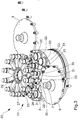
- a crimping machine predisposed to carry out the closure of containers 2 of the type of the bottles with a cap or ring nut 3 has been indicated in its entirety with 1.
- the machine 1 is provided with the crimping device 20 according to the present invention; the crimping device 20 provides to fasten the closure cap 3 on the neck of the bottles 2 with a prefixed crimping force.
- the machine 1 comprises a feed line 4 for the containers 2, made up of, for example, a conveyor belt.
- a separation device 5 made up, for example, of a screw element operated in rotation according to an axis parallel to the same feed line 4, spaces the containers 2 one another in regular manner.
- the containers 2, so spaced, are inserted in suitable seats of an inlet star-shaped distributor 6, rotatable according to a vertical axis to bring the same containers 2 to the crimping device 20.
- the containers 2 are provided with a respective closure cap 3, in known manner, through a supply member 7 fed by a vibrating container 8.
- the closed containers 2 are transferred in order to the corresponding seats of an outlet star-shaped distributor 9, rotatable according to a vertical axis to bring the same containers 2 to an exit line 10, made up, for example, of a conveyor belt.
- the passage of the containers 2 to the exit line 10 is possibly carried out by a second screw element 11 operated in rotation according to an axis parallel to the same exit line 10.
- the crimping machine is provided at its entry with a first waste device 12 for the containers 2 and at its exit with a second waste device 13 for the containers.
- the waste devices 12, 13 are made up of respective star-shaped distribution members, which are predisposed to convey the wasted containers to relative waste paths 14, 15.
- the passage of the wasted containers from the inlet distributor 6 to the entry waste device 12 and from the outlet distributor 9 to the exit waste device 15 is operated by the commutation of selection means with void connected with the above mentioned seats of the distribution members.
- the crimping device 20 comprises a turret 21 rotatable according to an axis vertical with respect to the fixed structure 16 of the machine.
- the turret 21 peripherally carries a plurality of support means 22 for the containers 2, respectively made up of plates carried by a lower drum 23 of the same turret 21; the drum 23 is fixed to the motor shaft 24 of the turret 21.
- the plates 22 are predisposed to be operated in rotation according to their own axis, with respect to the lower drum 23 of the turret 21, by respective operation means known per se.
- the plates 22 are as well predisposed to be operated in axial direction by respective operation means, not represented, to bring the containers 2 in abutment against corresponding abutment members 25 with a prefixed clamping force. More precisely, the abutment members 25 are predisposed to act as upper abutment for the closure cap 3 of the containers 2.
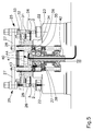
- the abutment members 25 comprise respectively an end element 26 associated with an arm 27 overhanging from a stem 28 having vertical axis (see in particular figure 5 ); the end element 26 is interchangeable according to the size of the cap 3 of the containers 2.
- the stem 28 is driven in rotation by an upper drum 29 of the turret 21, integral with the rotation of the motor shaft 24.
- the upper drum 29 is vertically mobile with respect to the motor shaft 24 of the turret 21 to allow the vertical adjustment of the abutment member 25 with respect to the container 2.
- the crimping device 20 comprises a plurality of crimping heads 30 carried by the turret 21 respectively at said support means 22.
- the crimping heads 30 respectively comprise a crimping blade 31, having circular shape, which is carried in rotatable manner according to a vertical axis by a rod 32 overhanging from a relative vertical stem 33.
- the crimping blade 31 is tilting, by means of an angular rotation of the stem 33, between a disengagement position and a working position, approached to the cap 3 of the relative container 2.
- the stem 33 is operated in rotation by an intermediate drum 34 of the turret 21, integral with the rotation of the motor shaft 24.
- the intermediate drum 34 has an angular position ⁇ adjustable with respect to the motor shaft 24 of the turret 21, so as to adjust the ruzement point of the forward stroke of the blade 31 towards the cap 3, the largeness of the movement being fixed. Moreover, the intermediate drum 34 is mobile vertically with respect to the motor shaft 24 of the turret 21 to allow the vertical adjustment of the crimping blade 31 with respect to the container 2.
- the crimping device 20 comprises transducer means 40 of measurement of an applied force, which are predisposed to carry out the control of the crimping force, detected by the abutment members 25.
- the transducer means 40 comprise a load cell 41, which is associated with the fixed framework 16 of the machine. More in particular, the load cell 41 is mounted at the top of a column 42 arranged coaxially inside the motor shaft 24 of the turret 21 and inferiorly fixed to the fixed framework 16 of the machine; the motor shaft 24 of the turret 21 has for this purpose a tubular shape.
- a radial tooth 43 is associated with the load cell 41, the radial tooth 43 being inserted in a corresponding opening of an annular cam 44, the annular cam 44 being constrained to the fixed framework 16 of the machine. Therefore, the tooth 43 is predisposed to restore the continuity of the upper surface of the annular cam 44, arranged on a horizontal plane and coaxial to the vertical axis of the turret 21.
- the annular cam 44 is engaged by a roller 35 carried, freely rotatable, by each stem 28 of the abutment members 25, on a respective pin 36, according to an axis radial to the same stem 28.
- the roller 35 is predisposed to transmit to the load cell 41 the tightening force of the cap 3 detected by the abutment members 25, to control the crimping force.
- a further roller 38 having axis radial to the same stem 28 is also carried rotatable on a respective pin 37.
- the further roller 38 engages a corresponding seat shaped by a crown 39 which is coaxially joined to the upper drum 29, to ensure the alignment of the arm 27 and consequently of the end element 26 of the abutment members 25 with the corresponding support plate 22 of the bottles 2. It is to be observed that the crown 39 does not prevent the displacement in vertical direction of the stem 28.
- the bottles 2, provided with a respective closure cap 3, are fed in succession from the inlet distributor 6 onto plates 22 that support the bottles 2 on the turret 21 of the crimping device.
- the turret 21 is rotatable according to an axis vertical with respect to the fixed framework 16 of the machine, to bring the same bottles 2 to the outlet distributor 9.
- the bottles 2 arranged in support on the plates 22 are driven in rotation according to their own axis, by effect of the rotation imposed to the same plates 22 by the respective operation means.
- the plates 22 are also operated in axial direction to bring the bottles 2 with their respective closure cap 3 in abutment against the corresponding upper abutment means 25.
- each crimping head 30 is operated in angular rotation to bring the crimping blade 31 in the working position approached to the cap 3.
- the axial rotation of the bottles 2 causes the crimping blade 31 to bend the rim of the cap 3 against the lower surface of the annular projection shaped by the neck of the bottles 2, along the whole circumference of the same cap 3, so as to create the ring nut.
- the device provides to transmit the clamping force detected by the end element 26 of the abutment members 25 to the overhanging, freely rotatable, roller 35 of the corresponding stem 28.
- the roller 35 moves on the annular path shaped by the cam 44, coaxial to the turret 21 but integral with the fixed structure 16 of the machine.
- the load cell 41 measures the applied force.
- the measurement point of the crimping force is adjusted so as to detect the tightening force after the plates 22 have completed the vertical compression stroke of the containers 2, that is when such force has reached the working value, but before the crimping head 30 is operated in angular rotation to bring the crimping blade 31 in the working position.
- the measurement performed by the load cell 41 is not affected by the disturbances caused by the components of the forces that arise during the crimping step.
- the stem 28 of the contrast means 25, which carries the roller 35 is held in its position by a plurality of revolving contacts, which have a limited starting friction and consequently do not affect in significant manner the measurement.
- the cited measurement point of the clamping force is adjustable by suitably varying the angular position ⁇ of the load cell 41 with respect to the turret 21 (see fig 6 ).
- the device according to the invention reaches therefore the scope of performing in an optimal way the crimping of containers such as bottles for medical use and the like.
- the crimping device according to the invention allows to measure exactly the pressure exerted trough the ring nut, so as to make safe the sealing closure of the bottles.
- the disclosed apparatus allows to exactly carry out the measurement of the force which has crossed the bottle, the cap and the ring nut, such force being detected on the upper abutment members and transmitted by them to the load cell.
- a feature of the invention is to carry out the measurement of the crimping force through the passage of suitable detection members of such force on a single load cell fixed to the structure of the machine and arranged at the upper zone of the turret carrying the bottles.
- the displacement of the load cell at the top of a column arranged coaxial inside a tubular shaft for the handling of the turret allows to ease the insertion of electrical cables linking the electrical control means.
- the embodiment of the invention may vary depending on the requirements.
Landscapes
- Engineering & Computer Science (AREA)
- Mechanical Engineering (AREA)
- Sealing Of Jars (AREA)
Claims (12)
- Crimpvorrichtung in einer Maschine zum Verschließen von Behältern, die Folgendes umfasst: ein Karussell (21), das um eine vertikale Achse gedreht werden kann, die peripherisch eine Mehrzahl an Stützmitteln (22) der mit einer Verschlusskapsel (3) ausgestatteten Behälter (2) trägt; Beförderungsmittel der genannten Stützmittel (22), um genannte Behälter (2) um ihre Achse zur Drehung zu bringen; eine entsprechende Mehrzahl an Crimpköpfen (30), die auf genanntem Karussell (21) jeweils auf die genannten Stützmittel (22) angebracht und jeweils mit einer Crimpklinge (31) versehen sind, die zwischen einer ausgerasteten Position und einer an genannte Kapsel (3) angenäherten Arbeitsposition schwenkt; eine Mehrzahl an von genanntem Karussell (21) getragenen Kontrastelementen (25), die geeignet sind, als oberer Anschlag für genannte Verschlusskapsel (3) der Behälter (2) zu dienen; dadurch gekennzeichnet dass, sie Mittel umfasst, die geeignet sind, genannte auf die genannten Stützmittel (22) gestützten Behälter (2) in axialer Richtung zu betätigen, um sie mit einer vorbestimmten Spannkraft (F) genannter Kapsel (3) bis zum Anschlag an die genannten Kontrastelemente (25) zu bringen; Wandlermittel (40) zur Messung einer angewandten Kraft, die mit einer zu genanntem Karussell (21) fixen Struktur (16) verbunden sind; Mittel (35), die geeignet sind, die von genannten Kontrastelementen (25) erfasste Spannkraft (F) genannter Kapsel (3) zur Kontrolle der Crimpkraft an genannte Wandlermittel (40) zu übertragen; wobei die genannte Wandlermittel (40) eine Ladezelle (41) umfassen, die an der Spitze genannter einteilig mit genannter fixer Struktur (16) verbundenen Auflagemittel (42) in einer im Wesentlichen zum genanntem Karussell (21) koaxialen Position angeordnet ist.
- Vorrichtung nach Anspruch 1, dadurch gekennzeichnet, dass genannte Ladezelle (41) auf das Oberteil des genannten Karussells (21) angeordnet ist.
- Vorrichtung nach Anspruch 1 oder 2, dadurch gekennzeichnet, dass genannte für die Übertragung der Spannkraft der genannten Kapsel (3) geeignete Mittel (35) Drehmittel (35) umfassen, die mit genannten Kontrastelementen (25) verbunden und geeignet sind, in einer Messphase die genannten Wandlermittel (40) anzugreifen.
- Vorrichtung nach Anspruch 3, dadurch gekennzeichnet, dass genannte Wandlermittel (40) mit einem radialen Element (43) verbunden sind, das in eine entsprechende Öffnung einer ringförmigen Nocke (44) eingefügt ist, einteilig mit genannter fixer Struktur (16) und koaxial zu genanntem Karussell (21), sodass die Kontinuität einer Oberfläche der genannten ringförmigen Nocke (44) wiederhergestellt wird, wobei genannte Drehmittel (35) geeignet sind, in genannter Messphase das genannte radiale Element (43) anzugreifen.
- Vorrichtung nach einem der vorhergehenden Ansprüche, dadurch gekennzeichnet, dass genannte Kontrastelemente (25) jeweils ein Endglied (26) umfassen, das auf austauschbare Weise mit einem von einem Ständer (28) vorspringenden Arm (27) mit einer vertikalen Achse verbunden ist, die von einer oberen Trommel (29) des genannten Karussells (21) in Drehung gebracht wird, die für die vertikale Regulierung der gleichen Kontrastelemente (25) zu genanntem Behälter (2) vertikal beweglich ist.
- Vorrichtung nach Ansprüche 4 und 5, dadurch gekennzeichnet, dass genannter Ständer (28) der Kontrastelemente (25) frei drehbar genannte Drehmittel (35) trägt, die geeignet sind, die genannten Wandlermittel (40) und weitere Drehmittel (38) anzugreifen, die geeignet sind, einen Sitz einer koaxial einteilig mit genanntem Karussell (21) verbundenen Krone anzugreifen, um die Ausrichtung zwischen den genannten Stützmitteln (22) der Behälter (2) und den Kontrastelementen (25) zu garantieren.
- Vorrichtung nach einem der vorhergehenden Ansprüche, dadurch gekennzeichnet, dass genannte Wandlermittel (40) eine Ladezelle (41) umfassen, die eine veränderliche Winkelposition (β) hat, um die Messstelle der genannten Spannkraft (F) zu regeln.
- Vorrichtung nach einem der vorhergehenden Ansprüche, dadurch gekennzeichnet, dass genannte Crimpfköpfe (33) mit einer Zwischentrommel (34) des genannten Karussells (21) verbunden sind, deren Winkelposition (α) zur vertikale Achse dieses Karussells (21) verstellbar ist, um den Annährungspunkt genannter Crimpklinge (31) an genannte Kapsel (3) zu regeln.
- Vorrichtung nach Anspruch 8, dadurch gekennzeichnet, dass genannte Zwischentrommel (34) vertikal beweglich ist, sodass die vertikale Regulierung genannter Crimpklingen (31) zu den genannten Behältern (2) ermöglicht wird.
- Crimpverfahren in einer Maschine zum Verschließen von Behältern, dadurch gekennzeichnet, dass folgende Schritte vorgesehen sind:a. die mit einer Verschlusskapsel (3) versehenen Behälter (2) nacheinander auf jeweiligen Stützmitteln (22) anzuordnen, die peripherisch von einem um eine vertikale Achse drehbaren Karussell (21) getragen werden;b. genannte Stützmittel (22) in axialer Richtung nach oben zu betätigen, um genannte Behälter (2) mit einer vorbestimmten Spannkraft (F) der Kapsel (3) bis zum Anschlag an die jeweiligen Kontrastelemente (25) zu bringen, die geeignet sind, genannter Verschlusskapsel (3) der Behälter (2) als oberer Anschlag zu dienen;c. genannte von den genannten Kontrastelementen (25) erfasste Spannkraft (F) der genannten Kapsel (3) an Wandlermittel (40), die eine Ladezelle (41) umfassen, die an der Spitze genannter einteilig mit genannter fixer Struktur (16) verbundenen Auflagemittel (42) in einer im Wesentlichen zum genanntem Karussell (21) koaxialen Position angeordnet ist, zu übertragen.
- Verfahren nach Anspruch 10, dadurch gekennzeichnet, dass genannte Spannkraft (F) geeignet ist, während einer Crimpphase einen Vorladedruck auf genannte Kapsel (3) zu liefern.
- Verfahren nach Anspruch 10 oder 11, dadurch gekennzeichnet, dass vorgesehen ist, dass genannte Spannkraft (F) gemessen wird, wenn die genannten Stützmittel (22) den Vertikalhub zur Pressung der genannten Behälter (2) abgeschlossen haben, das heißt, nachdem diese Kraft den Betriebswert erreicht hat, aber vor Beginn der genannten Crimpphase.
Applications Claiming Priority (1)
| Application Number | Priority Date | Filing Date | Title |
|---|---|---|---|
| ITBO20140159 | 2014-03-25 |
Publications (2)
| Publication Number | Publication Date |
|---|---|
| EP2923996A1 EP2923996A1 (de) | 2015-09-30 |
| EP2923996B1 true EP2923996B1 (de) | 2016-11-09 |
Family
ID=50693740
Family Applications (1)
| Application Number | Title | Priority Date | Filing Date |
|---|---|---|---|
| EP15160412.1A Active EP2923996B1 (de) | 2014-03-25 | 2015-03-23 | Crimpvorrichtung für eine maschine zum verschliessen von behältern |
Country Status (1)
| Country | Link |
|---|---|
| EP (1) | EP2923996B1 (de) |
Cited By (1)
| Publication number | Priority date | Publication date | Assignee | Title |
|---|---|---|---|---|
| IT202100026087A1 (it) * | 2021-10-12 | 2023-04-12 | Gd Spa | Macchina ghieratrice e relativo metodo di controllo |
Families Citing this family (3)
| Publication number | Priority date | Publication date | Assignee | Title |
|---|---|---|---|---|
| CN106430045B (zh) * | 2016-11-28 | 2019-05-03 | 长沙今朝科技股份有限公司 | 一种压盖装置、包装设备及灌装生产线 |
| CN112047275B (zh) * | 2020-08-17 | 2022-01-25 | 山东中成包装科技有限公司 | 一种桶体结构桶盖安装用多工位型紧固结构 |
| DE102021104302A1 (de) * | 2021-02-23 | 2022-08-25 | Syntegon Technology Gmbh | Vorrichtung und Verfahren zum kraftgesteuerten Verschließen von pharmazeutischen Behältnissen |
Family Cites Families (4)
| Publication number | Priority date | Publication date | Assignee | Title |
|---|---|---|---|---|
| DE4442035A1 (de) | 1994-11-25 | 1996-05-30 | Groninger & Co Gmbh | Vorrichtung zum Verschließen von Flaschen durch Bördeln |
| US6367301B1 (en) | 2000-09-15 | 2002-04-09 | Capmatic Ltd. | High speed crimping apparatus |
| JP4370976B2 (ja) * | 2004-05-21 | 2009-11-25 | 澁谷工業株式会社 | シール荷重検査装置 |
| DE102007016249A1 (de) | 2007-04-04 | 2008-10-09 | Robert Bosch Gmbh | Verpackungsmaschine |
-
2015
- 2015-03-23 EP EP15160412.1A patent/EP2923996B1/de active Active
Cited By (3)
| Publication number | Priority date | Publication date | Assignee | Title |
|---|---|---|---|---|
| IT202100026087A1 (it) * | 2021-10-12 | 2023-04-12 | Gd Spa | Macchina ghieratrice e relativo metodo di controllo |
| EP4166493A1 (de) * | 2021-10-12 | 2023-04-19 | G.D S.p.A. | Siegelmaschine und zugehöriges steuerungsverfahren |
| US12311429B2 (en) | 2021-10-12 | 2025-05-27 | G.D S.P.A. | Sealing machine and related control method |
Also Published As
| Publication number | Publication date |
|---|---|
| EP2923996A1 (de) | 2015-09-30 |
Similar Documents
| Publication | Publication Date | Title |
|---|---|---|
| EP2923996B1 (de) | Crimpvorrichtung für eine maschine zum verschliessen von behältern | |
| US9090408B2 (en) | Apparatus and method of conveying containers with base guidance | |
| EP1995208B1 (de) | Rotationsfüllmaschine zur Füllung von Behältern mit Flüssigkeiten | |
| EP1646579B9 (de) | Verschliesseinheit zum schliessen von behältern mit jeweiligen kappen | |
| US9624039B2 (en) | Method and container-processing machine for processing containers | |
| US7059104B2 (en) | System for filling and closing fluid containing cartridges | |
| US10519018B2 (en) | Receptacle handling apparatus for filing and capping receptacles | |
| EP3386905B1 (de) | Maschine zum befüllen von flaschen dosen und ähnliche behälter | |
| CN104995092B (zh) | 用于为药瓶加盖和密封的装置和方法 | |
| CN115367687A (zh) | 用于封闭容器的封盖装置和封盖机 | |
| EP3162721A1 (de) | Vorrichtung zur handhabung von behältern | |
| EP1273551B1 (de) | Verschliesseinrichtung mit einem Verschliesskopf | |
| EP0677482B1 (de) | Vorrichtung zum Verschliessen von Flaschen und dergleichen mit Schraubverschlüssen | |
| EP2733112B1 (de) | Verfahren und Vorrichtung zum Versiegeln von Kapseln auf Flaschenhälsen mit einem Haltekäfig aus Metalldraht. | |
| CN105217547B (zh) | 一种用于对塑料瓶执行多个操作的容器处理装置 | |
| EP2792634B1 (de) | Positionssteuerungssystem für eine Artikelhandhabungsmaschine und zugehöriges Verfahren | |
| EP2990344B1 (de) | Behälterbehandlungsmaschine und -Verfahren | |
| EP2206676B1 (de) | Verschliesskopf zum Anbringen von Verschlüssen auf Gefässe | |
| US10040590B2 (en) | Container handling machine and method | |
| EP2594524B1 (de) | Maschine zum Füllen von Behältern mit Flüssigkeiten | |
| CN205186562U (zh) | 一种食品机械自动化包装装置 | |
| EP2058271A1 (de) | Kugelgelenkkopf zur Befestigung von Versiegelungskapseln eines Ertragmaterials um Flaschenhälse für Wein-, Likör- und ähnliche Flaschen | |
| US900550A (en) | Machine for securing sealing-caps to bottles. |
Legal Events
| Date | Code | Title | Description |
|---|---|---|---|
| PUAI | Public reference made under article 153(3) epc to a published international application that has entered the european phase |
Free format text: ORIGINAL CODE: 0009012 |
|
| AK | Designated contracting states |
Kind code of ref document: A1 Designated state(s): AL AT BE BG CH CY CZ DE DK EE ES FI FR GB GR HR HU IE IS IT LI LT LU LV MC MK MT NL NO PL PT RO RS SE SI SK SM TR |
|
| AX | Request for extension of the european patent |
Extension state: BA ME |
|
| 17P | Request for examination filed |
Effective date: 20160330 |
|
| RBV | Designated contracting states (corrected) |
Designated state(s): AL AT BE BG CH CY CZ DE DK EE ES FI FR GB GR HR HU IE IS IT LI LT LU LV MC MK MT NL NO PL PT RO RS SE SI SK SM TR |
|
| GRAP | Despatch of communication of intention to grant a patent |
Free format text: ORIGINAL CODE: EPIDOSNIGR1 |
|
| RIC1 | Information provided on ipc code assigned before grant |
Ipc: B21D 51/32 20060101ALI20160425BHEP Ipc: B65B 7/28 20060101ALI20160425BHEP Ipc: B67B 3/10 20060101AFI20160425BHEP Ipc: B67B 3/26 20060101ALI20160425BHEP |
|
| INTG | Intention to grant announced |
Effective date: 20160523 |
|
| GRAS | Grant fee paid |
Free format text: ORIGINAL CODE: EPIDOSNIGR3 |
|
| GRAA | (expected) grant |
Free format text: ORIGINAL CODE: 0009210 |
|
| AK | Designated contracting states |
Kind code of ref document: B1 Designated state(s): AL AT BE BG CH CY CZ DE DK EE ES FI FR GB GR HR HU IE IS IT LI LT LU LV MC MK MT NL NO PL PT RO RS SE SI SK SM TR |
|
| REG | Reference to a national code |
Ref country code: GB Ref legal event code: FG4D |
|
| REG | Reference to a national code |
Ref country code: AT Ref legal event code: REF Ref document number: 843723 Country of ref document: AT Kind code of ref document: T Effective date: 20161115 Ref country code: CH Ref legal event code: EP |
|
| REG | Reference to a national code |
Ref country code: IE Ref legal event code: FG4D |
|
| REG | Reference to a national code |
Ref country code: DE Ref legal event code: R096 Ref document number: 602015000652 Country of ref document: DE |
|
| PG25 | Lapsed in a contracting state [announced via postgrant information from national office to epo] |
Ref country code: LV Free format text: LAPSE BECAUSE OF FAILURE TO SUBMIT A TRANSLATION OF THE DESCRIPTION OR TO PAY THE FEE WITHIN THE PRESCRIBED TIME-LIMIT Effective date: 20161109 |
|
| REG | Reference to a national code |
Ref country code: LT Ref legal event code: MG4D |
|
| REG | Reference to a national code |
Ref country code: NL Ref legal event code: MP Effective date: 20161109 |
|
| REG | Reference to a national code |
Ref country code: AT Ref legal event code: MK05 Ref document number: 843723 Country of ref document: AT Kind code of ref document: T Effective date: 20161109 |
|
| PG25 | Lapsed in a contracting state [announced via postgrant information from national office to epo] |
Ref country code: SE Free format text: LAPSE BECAUSE OF FAILURE TO SUBMIT A TRANSLATION OF THE DESCRIPTION OR TO PAY THE FEE WITHIN THE PRESCRIBED TIME-LIMIT Effective date: 20161109 Ref country code: NL Free format text: LAPSE BECAUSE OF FAILURE TO SUBMIT A TRANSLATION OF THE DESCRIPTION OR TO PAY THE FEE WITHIN THE PRESCRIBED TIME-LIMIT Effective date: 20161109 Ref country code: LT Free format text: LAPSE BECAUSE OF FAILURE TO SUBMIT A TRANSLATION OF THE DESCRIPTION OR TO PAY THE FEE WITHIN THE PRESCRIBED TIME-LIMIT Effective date: 20161109 Ref country code: NO Free format text: LAPSE BECAUSE OF FAILURE TO SUBMIT A TRANSLATION OF THE DESCRIPTION OR TO PAY THE FEE WITHIN THE PRESCRIBED TIME-LIMIT Effective date: 20170209 Ref country code: GR Free format text: LAPSE BECAUSE OF FAILURE TO SUBMIT A TRANSLATION OF THE DESCRIPTION OR TO PAY THE FEE WITHIN THE PRESCRIBED TIME-LIMIT Effective date: 20170210 |
|
| PG25 | Lapsed in a contracting state [announced via postgrant information from national office to epo] |
Ref country code: IS Free format text: LAPSE BECAUSE OF FAILURE TO SUBMIT A TRANSLATION OF THE DESCRIPTION OR TO PAY THE FEE WITHIN THE PRESCRIBED TIME-LIMIT Effective date: 20170309 Ref country code: PT Free format text: LAPSE BECAUSE OF FAILURE TO SUBMIT A TRANSLATION OF THE DESCRIPTION OR TO PAY THE FEE WITHIN THE PRESCRIBED TIME-LIMIT Effective date: 20170309 Ref country code: RS Free format text: LAPSE BECAUSE OF FAILURE TO SUBMIT A TRANSLATION OF THE DESCRIPTION OR TO PAY THE FEE WITHIN THE PRESCRIBED TIME-LIMIT Effective date: 20161109 Ref country code: PL Free format text: LAPSE BECAUSE OF FAILURE TO SUBMIT A TRANSLATION OF THE DESCRIPTION OR TO PAY THE FEE WITHIN THE PRESCRIBED TIME-LIMIT Effective date: 20161109 Ref country code: ES Free format text: LAPSE BECAUSE OF FAILURE TO SUBMIT A TRANSLATION OF THE DESCRIPTION OR TO PAY THE FEE WITHIN THE PRESCRIBED TIME-LIMIT Effective date: 20161109 Ref country code: FI Free format text: LAPSE BECAUSE OF FAILURE TO SUBMIT A TRANSLATION OF THE DESCRIPTION OR TO PAY THE FEE WITHIN THE PRESCRIBED TIME-LIMIT Effective date: 20161109 Ref country code: HR Free format text: LAPSE BECAUSE OF FAILURE TO SUBMIT A TRANSLATION OF THE DESCRIPTION OR TO PAY THE FEE WITHIN THE PRESCRIBED TIME-LIMIT Effective date: 20161109 Ref country code: AT Free format text: LAPSE BECAUSE OF FAILURE TO SUBMIT A TRANSLATION OF THE DESCRIPTION OR TO PAY THE FEE WITHIN THE PRESCRIBED TIME-LIMIT Effective date: 20161109 |
|
| PG25 | Lapsed in a contracting state [announced via postgrant information from national office to epo] |
Ref country code: DK Free format text: LAPSE BECAUSE OF FAILURE TO SUBMIT A TRANSLATION OF THE DESCRIPTION OR TO PAY THE FEE WITHIN THE PRESCRIBED TIME-LIMIT Effective date: 20161109 Ref country code: SK Free format text: LAPSE BECAUSE OF FAILURE TO SUBMIT A TRANSLATION OF THE DESCRIPTION OR TO PAY THE FEE WITHIN THE PRESCRIBED TIME-LIMIT Effective date: 20161109 Ref country code: RO Free format text: LAPSE BECAUSE OF FAILURE TO SUBMIT A TRANSLATION OF THE DESCRIPTION OR TO PAY THE FEE WITHIN THE PRESCRIBED TIME-LIMIT Effective date: 20161109 Ref country code: CZ Free format text: LAPSE BECAUSE OF FAILURE TO SUBMIT A TRANSLATION OF THE DESCRIPTION OR TO PAY THE FEE WITHIN THE PRESCRIBED TIME-LIMIT Effective date: 20161109 Ref country code: EE Free format text: LAPSE BECAUSE OF FAILURE TO SUBMIT A TRANSLATION OF THE DESCRIPTION OR TO PAY THE FEE WITHIN THE PRESCRIBED TIME-LIMIT Effective date: 20161109 |
|
| REG | Reference to a national code |
Ref country code: DE Ref legal event code: R097 Ref document number: 602015000652 Country of ref document: DE |
|
| PG25 | Lapsed in a contracting state [announced via postgrant information from national office to epo] |
Ref country code: BG Free format text: LAPSE BECAUSE OF FAILURE TO SUBMIT A TRANSLATION OF THE DESCRIPTION OR TO PAY THE FEE WITHIN THE PRESCRIBED TIME-LIMIT Effective date: 20170209 Ref country code: BE Free format text: LAPSE BECAUSE OF FAILURE TO SUBMIT A TRANSLATION OF THE DESCRIPTION OR TO PAY THE FEE WITHIN THE PRESCRIBED TIME-LIMIT Effective date: 20161109 Ref country code: SM Free format text: LAPSE BECAUSE OF FAILURE TO SUBMIT A TRANSLATION OF THE DESCRIPTION OR TO PAY THE FEE WITHIN THE PRESCRIBED TIME-LIMIT Effective date: 20161109 |
|
| PLBE | No opposition filed within time limit |
Free format text: ORIGINAL CODE: 0009261 |
|
| STAA | Information on the status of an ep patent application or granted ep patent |
Free format text: STATUS: NO OPPOSITION FILED WITHIN TIME LIMIT |
|
| 26N | No opposition filed |
Effective date: 20170810 |
|
| PG25 | Lapsed in a contracting state [announced via postgrant information from national office to epo] |
Ref country code: MC Free format text: LAPSE BECAUSE OF FAILURE TO SUBMIT A TRANSLATION OF THE DESCRIPTION OR TO PAY THE FEE WITHIN THE PRESCRIBED TIME-LIMIT Effective date: 20161109 Ref country code: SI Free format text: LAPSE BECAUSE OF FAILURE TO SUBMIT A TRANSLATION OF THE DESCRIPTION OR TO PAY THE FEE WITHIN THE PRESCRIBED TIME-LIMIT Effective date: 20161109 |
|
| REG | Reference to a national code |
Ref country code: IE Ref legal event code: MM4A |
|
| REG | Reference to a national code |
Ref country code: FR Ref legal event code: ST Effective date: 20171130 |
|
| PG25 | Lapsed in a contracting state [announced via postgrant information from national office to epo] |
Ref country code: FR Free format text: LAPSE BECAUSE OF NON-PAYMENT OF DUE FEES Effective date: 20170331 Ref country code: LU Free format text: LAPSE BECAUSE OF NON-PAYMENT OF DUE FEES Effective date: 20170323 |
|
| PG25 | Lapsed in a contracting state [announced via postgrant information from national office to epo] |
Ref country code: IE Free format text: LAPSE BECAUSE OF NON-PAYMENT OF DUE FEES Effective date: 20170323 |
|
| PG25 | Lapsed in a contracting state [announced via postgrant information from national office to epo] |
Ref country code: MT Free format text: LAPSE BECAUSE OF NON-PAYMENT OF DUE FEES Effective date: 20170323 |
|
| REG | Reference to a national code |
Ref country code: CH Ref legal event code: PL |
|
| PG25 | Lapsed in a contracting state [announced via postgrant information from national office to epo] |
Ref country code: CH Free format text: LAPSE BECAUSE OF NON-PAYMENT OF DUE FEES Effective date: 20180331 Ref country code: LI Free format text: LAPSE BECAUSE OF NON-PAYMENT OF DUE FEES Effective date: 20180331 |
|
| PG25 | Lapsed in a contracting state [announced via postgrant information from national office to epo] |
Ref country code: HU Free format text: LAPSE BECAUSE OF FAILURE TO SUBMIT A TRANSLATION OF THE DESCRIPTION OR TO PAY THE FEE WITHIN THE PRESCRIBED TIME-LIMIT; INVALID AB INITIO Effective date: 20150323 |
|
| PG25 | Lapsed in a contracting state [announced via postgrant information from national office to epo] |
Ref country code: CY Free format text: LAPSE BECAUSE OF FAILURE TO SUBMIT A TRANSLATION OF THE DESCRIPTION OR TO PAY THE FEE WITHIN THE PRESCRIBED TIME-LIMIT Effective date: 20161109 |
|
| GBPC | Gb: european patent ceased through non-payment of renewal fee |
Effective date: 20190323 |
|
| PG25 | Lapsed in a contracting state [announced via postgrant information from national office to epo] |
Ref country code: MK Free format text: LAPSE BECAUSE OF FAILURE TO SUBMIT A TRANSLATION OF THE DESCRIPTION OR TO PAY THE FEE WITHIN THE PRESCRIBED TIME-LIMIT Effective date: 20161109 |
|
| PG25 | Lapsed in a contracting state [announced via postgrant information from national office to epo] |
Ref country code: GB Free format text: LAPSE BECAUSE OF NON-PAYMENT OF DUE FEES Effective date: 20190323 |
|
| PG25 | Lapsed in a contracting state [announced via postgrant information from national office to epo] |
Ref country code: TR Free format text: LAPSE BECAUSE OF FAILURE TO SUBMIT A TRANSLATION OF THE DESCRIPTION OR TO PAY THE FEE WITHIN THE PRESCRIBED TIME-LIMIT Effective date: 20161109 |
|
| PG25 | Lapsed in a contracting state [announced via postgrant information from national office to epo] |
Ref country code: AL Free format text: LAPSE BECAUSE OF FAILURE TO SUBMIT A TRANSLATION OF THE DESCRIPTION OR TO PAY THE FEE WITHIN THE PRESCRIBED TIME-LIMIT Effective date: 20161109 |
|
| P01 | Opt-out of the competence of the unified patent court (upc) registered |
Effective date: 20230502 |
|
| PGFP | Annual fee paid to national office [announced via postgrant information from national office to epo] |
Ref country code: DE Payment date: 20250429 Year of fee payment: 11 |
|
| PGFP | Annual fee paid to national office [announced via postgrant information from national office to epo] |
Ref country code: IT Payment date: 20250331 Year of fee payment: 11 |