EP2924182A2 - Pelleteuse et son procédé de contrôle - Google Patents
Pelleteuse et son procédé de contrôle Download PDFInfo
- Publication number
- EP2924182A2 EP2924182A2 EP15160438.6A EP15160438A EP2924182A2 EP 2924182 A2 EP2924182 A2 EP 2924182A2 EP 15160438 A EP15160438 A EP 15160438A EP 2924182 A2 EP2924182 A2 EP 2924182A2
- Authority
- EP
- European Patent Office
- Prior art keywords
- turning
- shovel
- hydraulic
- operating oil
- entering object
- Prior art date
- Legal status (The legal status is an assumption and is not a legal conclusion. Google has not performed a legal analysis and makes no representation as to the accuracy of the status listed.)
- Granted
Links
Images


Classifications
-
- E—FIXED CONSTRUCTIONS
- E02—HYDRAULIC ENGINEERING; FOUNDATIONS; SOIL SHIFTING
- E02F—DREDGING; SOIL-SHIFTING
- E02F9/00—Component parts of dredgers or soil-shifting machines, not restricted to one of the kinds covered by groups E02F3/00 - E02F7/00
- E02F9/20—Drives; Control devices
- E02F9/2025—Particular purposes of control systems not otherwise provided for
- E02F9/2033—Limiting the movement of frames or implements, e.g. to avoid collision between implements and the cabin
-
- E—FIXED CONSTRUCTIONS
- E02—HYDRAULIC ENGINEERING; FOUNDATIONS; SOIL SHIFTING
- E02F—DREDGING; SOIL-SHIFTING
- E02F3/00—Dredgers; Soil-shifting machines
- E02F3/04—Dredgers; Soil-shifting machines mechanically-driven
- E02F3/28—Dredgers; Soil-shifting machines mechanically-driven with digging tools mounted on a dipper- or bucket-arm, i.e. there is either one arm or a pair of arms, e.g. dippers, buckets
- E02F3/36—Component parts
- E02F3/42—Drives for dippers, buckets, dipper-arms or bucket-arms
- E02F3/43—Control of dipper or bucket position; Control of sequence of drive operations
- E02F3/435—Control of dipper or bucket position; Control of sequence of drive operations for dipper-arms, backhoes or the like
-
- E—FIXED CONSTRUCTIONS
- E02—HYDRAULIC ENGINEERING; FOUNDATIONS; SOIL SHIFTING
- E02F—DREDGING; SOIL-SHIFTING
- E02F9/00—Component parts of dredgers or soil-shifting machines, not restricted to one of the kinds covered by groups E02F3/00 - E02F7/00
- E02F9/08—Superstructures; Supports for superstructures
- E02F9/10—Supports for movable superstructures mounted on travelling or walking gears or on other superstructures
- E02F9/12—Slewing or traversing gears
- E02F9/121—Turntables, i.e. structure rotatable about 360°
- E02F9/123—Drives or control devices specially adapted therefor
-
- E—FIXED CONSTRUCTIONS
- E02—HYDRAULIC ENGINEERING; FOUNDATIONS; SOIL SHIFTING
- E02F—DREDGING; SOIL-SHIFTING
- E02F9/00—Component parts of dredgers or soil-shifting machines, not restricted to one of the kinds covered by groups E02F3/00 - E02F7/00
- E02F9/08—Superstructures; Supports for superstructures
- E02F9/10—Supports for movable superstructures mounted on travelling or walking gears or on other superstructures
- E02F9/12—Slewing or traversing gears
- E02F9/121—Turntables, i.e. structure rotatable about 360°
- E02F9/128—Braking systems
-
- E—FIXED CONSTRUCTIONS
- E02—HYDRAULIC ENGINEERING; FOUNDATIONS; SOIL SHIFTING
- E02F—DREDGING; SOIL-SHIFTING
- E02F9/00—Component parts of dredgers or soil-shifting machines, not restricted to one of the kinds covered by groups E02F3/00 - E02F7/00
- E02F9/20—Drives; Control devices
- E02F9/22—Hydraulic or pneumatic drives
- E02F9/2278—Hydraulic circuits
- E02F9/2282—Systems using center bypass type changeover valves
-
- E—FIXED CONSTRUCTIONS
- E02—HYDRAULIC ENGINEERING; FOUNDATIONS; SOIL SHIFTING
- E02F—DREDGING; SOIL-SHIFTING
- E02F9/00—Component parts of dredgers or soil-shifting machines, not restricted to one of the kinds covered by groups E02F3/00 - E02F7/00
- E02F9/20—Drives; Control devices
- E02F9/22—Hydraulic or pneumatic drives
- E02F9/2278—Hydraulic circuits
- E02F9/2285—Pilot-operated systems
-
- E—FIXED CONSTRUCTIONS
- E02—HYDRAULIC ENGINEERING; FOUNDATIONS; SOIL SHIFTING
- E02F—DREDGING; SOIL-SHIFTING
- E02F9/00—Component parts of dredgers or soil-shifting machines, not restricted to one of the kinds covered by groups E02F3/00 - E02F7/00
- E02F9/20—Drives; Control devices
- E02F9/22—Hydraulic or pneumatic drives
- E02F9/2278—Hydraulic circuits
- E02F9/2292—Systems with two or more pumps
-
- E—FIXED CONSTRUCTIONS
- E02—HYDRAULIC ENGINEERING; FOUNDATIONS; SOIL SHIFTING
- E02F—DREDGING; SOIL-SHIFTING
- E02F9/00—Component parts of dredgers or soil-shifting machines, not restricted to one of the kinds covered by groups E02F3/00 - E02F7/00
- E02F9/20—Drives; Control devices
- E02F9/22—Hydraulic or pneumatic drives
- E02F9/2278—Hydraulic circuits
- E02F9/2296—Systems with a variable displacement pump
-
- E—FIXED CONSTRUCTIONS
- E02—HYDRAULIC ENGINEERING; FOUNDATIONS; SOIL SHIFTING
- E02F—DREDGING; SOIL-SHIFTING
- E02F9/00—Component parts of dredgers or soil-shifting machines, not restricted to one of the kinds covered by groups E02F3/00 - E02F7/00
- E02F9/26—Indicating devices
- E02F9/261—Surveying the work-site to be treated
- E02F9/262—Surveying the work-site to be treated with follow-up actions to control the work tool, e.g. controller
-
- F—MECHANICAL ENGINEERING; LIGHTING; HEATING; WEAPONS; BLASTING
- F16—ENGINEERING ELEMENTS AND UNITS; GENERAL MEASURES FOR PRODUCING AND MAINTAINING EFFECTIVE FUNCTIONING OF MACHINES OR INSTALLATIONS; THERMAL INSULATION IN GENERAL
- F16P—SAFETY DEVICES IN GENERAL; SAFETY DEVICES FOR PRESSES
- F16P3/00—Safety devices acting in conjunction with the control or operation of a machine; Control arrangements requiring the simultaneous use of two or more parts of the body
- F16P3/12—Safety devices acting in conjunction with the control or operation of a machine; Control arrangements requiring the simultaneous use of two or more parts of the body with means, e.g. feelers, which in case of the presence of a body part of a person in or near the danger zone influence the control or operation of the machine
- F16P3/14—Safety devices acting in conjunction with the control or operation of a machine; Control arrangements requiring the simultaneous use of two or more parts of the body with means, e.g. feelers, which in case of the presence of a body part of a person in or near the danger zone influence the control or operation of the machine the means being photocells or other devices sensitive without mechanical contact
- F16P3/141—Safety devices acting in conjunction with the control or operation of a machine; Control arrangements requiring the simultaneous use of two or more parts of the body with means, e.g. feelers, which in case of the presence of a body part of a person in or near the danger zone influence the control or operation of the machine the means being photocells or other devices sensitive without mechanical contact using sound propagation, e.g. sonar
-
- F—MECHANICAL ENGINEERING; LIGHTING; HEATING; WEAPONS; BLASTING
- F16—ENGINEERING ELEMENTS AND UNITS; GENERAL MEASURES FOR PRODUCING AND MAINTAINING EFFECTIVE FUNCTIONING OF MACHINES OR INSTALLATIONS; THERMAL INSULATION IN GENERAL
- F16P—SAFETY DEVICES IN GENERAL; SAFETY DEVICES FOR PRESSES
- F16P3/00—Safety devices acting in conjunction with the control or operation of a machine; Control arrangements requiring the simultaneous use of two or more parts of the body
- F16P3/12—Safety devices acting in conjunction with the control or operation of a machine; Control arrangements requiring the simultaneous use of two or more parts of the body with means, e.g. feelers, which in case of the presence of a body part of a person in or near the danger zone influence the control or operation of the machine
- F16P3/14—Safety devices acting in conjunction with the control or operation of a machine; Control arrangements requiring the simultaneous use of two or more parts of the body with means, e.g. feelers, which in case of the presence of a body part of a person in or near the danger zone influence the control or operation of the machine the means being photocells or other devices sensitive without mechanical contact
- F16P3/142—Safety devices acting in conjunction with the control or operation of a machine; Control arrangements requiring the simultaneous use of two or more parts of the body with means, e.g. feelers, which in case of the presence of a body part of a person in or near the danger zone influence the control or operation of the machine the means being photocells or other devices sensitive without mechanical contact using image capturing devices
-
- F—MECHANICAL ENGINEERING; LIGHTING; HEATING; WEAPONS; BLASTING
- F16—ENGINEERING ELEMENTS AND UNITS; GENERAL MEASURES FOR PRODUCING AND MAINTAINING EFFECTIVE FUNCTIONING OF MACHINES OR INSTALLATIONS; THERMAL INSULATION IN GENERAL
- F16P—SAFETY DEVICES IN GENERAL; SAFETY DEVICES FOR PRESSES
- F16P3/00—Safety devices acting in conjunction with the control or operation of a machine; Control arrangements requiring the simultaneous use of two or more parts of the body
- F16P3/12—Safety devices acting in conjunction with the control or operation of a machine; Control arrangements requiring the simultaneous use of two or more parts of the body with means, e.g. feelers, which in case of the presence of a body part of a person in or near the danger zone influence the control or operation of the machine
- F16P3/14—Safety devices acting in conjunction with the control or operation of a machine; Control arrangements requiring the simultaneous use of two or more parts of the body with means, e.g. feelers, which in case of the presence of a body part of a person in or near the danger zone influence the control or operation of the machine the means being photocells or other devices sensitive without mechanical contact
- F16P3/147—Safety devices acting in conjunction with the control or operation of a machine; Control arrangements requiring the simultaneous use of two or more parts of the body with means, e.g. feelers, which in case of the presence of a body part of a person in or near the danger zone influence the control or operation of the machine the means being photocells or other devices sensitive without mechanical contact using electro-magnetic technology, e.g. tags or radar
Definitions
- the present invention relates to a shovel having a turning body mounted on a running body, and a control method thereof.
- a shovel including a lower running body and an upper turning body that is turnably provided on the lower running body.
- An engine is mounted on the upper turning body.
- a hydraulic pump is driven by the engine to discharge an operating oil.
- a hydraulic actuator is mounted on the upper turning body.
- a control device controls operations of the shovel.
- An entering object detection device detects a position of an entering object in a monitoring area of the shovel and outputs a detection signal indicating the detection position of the entering object.
- the control device supplies, after a determination of an entry of the entering object into the monitoring area, the operating oil from the hydraulic pump to the hydraulic actuator.
- a control method of a shovel that includes a control device that controls operations of the shovel, and an entering object detection device that detects a position of an entering object that has entered a monitoring area of the shovel.
- the control method includes determining an entry of the entering object into the monitoring area based on a detection signal from the entering object detection device; and supplying an operating oil from a hydraulic pump to a hydraulic actuator after the determination of an entry of the entering object.
- FIG. 1 is a side view of the shovel according to the embodiment.
- the shovel illustrated in FIG. 1 includes a lower running body 1 and an upper turning body 3 that is mounted on the lower running body 1 via a turning mechanism 2.
- a boom 4 is mounted to the upper turning body 3.
- An arm 5 is attached to an extreme end of the boom 4, and the bucket 6 is attached to an extreme end of the arm 5.
- the boom 4, arm 5 and bucket 6 (corresponding to an attachment 125 mentioned later) are hydraulically driven by a boom cylinder 7, an arm cylinder 8 and a bucket cylinder 9, respectively.
- the upper turning body 3 is provided with a cabin 10 and also mounted with a power source such as an engine 11 or the like.
- the cabin 10 is provided with a driver's seat so that a driver can operate the shovel while sitting in the driver's seat.
- FIG. 2 is a block diagram illustrating a structure of a drive system of the shovel illustrated in FIG. 1 .
- double lines denote a mechanical drive system
- bold solid lines denote high-pressure hydraulic lines
- thin dashed lines denote pilot lines
- bold dotted lines denote electric drive/control lines.
- the drive system of the shovel mainly includes an engine 11, a regulator 13, a main pump 14, a pilot pump 15, a control valve 17, an operation device 26, a pressure sensor 29, and a controller 30.
- the engine 11 is a power source of the shovel, which, for example, operates to maintain a predetermined revolution speed.
- the output axis of the engine 11 is connected to the input axis of the main pump 14.
- the main pump 14 is a hydraulic pump for supplying operating oil to the control valve 17 through a high-pressure hydraulic line, and is, for example, a swash plate type variable capacity hydraulic pump.
- the main pump 14 discharges the operating oil by the revolution power of the engine 11.
- the regulator 13 is a device for controlling an amount of discharge of the main pump 14.
- the regulator 13 controls an amount of discharge of the main pump 14 by, for example, adjusting a swash plate inclination angle of the main pump 14 in response to a discharge pressure of the main pump 14 or a control signal from the controller 30.
- the pilot pump 15 is a hydraulic pump for supplying operating oil to various hydraulically controlled devices through a pilot line, and is, for example, a fixed capacity hydraulic pump.
- the pilot pump 15 is connected with an operation device 26 through a pilot line 25.
- the control valve 17 is a hydraulic control device for controlling a hydraulic system in the shovel.
- the boom cylinder 7, the arm cylinder 8, the bucket cylinder 9, a running hydraulic motor 1A (right), a running hydraulic motor 1B (left) and a turning hydraulic motor 21 are connected to the control valve 17 through high-pressure hydraulic lines.
- the control valve 17 selectively supplies operating oil discharged by the main pump 14 to one or more of the boom cylinder 7, the arm cylinder 8, the bucket cylinder 9, the running hydraulic motor 1A (right), the running hydraulic motor 1B (left) and the turning hydraulic motor 21.
- the boom cylinder 7, the arm cylinder 8, the bucket cylinder 9, the running hydraulic motor 1A (left), the running hydraulic motor 1B (right) and the turning hydraulic motor 21 may be collectively referred to as the "hydraulic actuators".
- the operation device 26 includes a lever 26A, a lever 26B and a pedal 26C.
- the levers 26A, 26B and 26C are connected to the control valve 17 and a pressure sensor 29 through pilot lines 27 and 28, respectively.
- the pressure sensor 29 is connected to a controller 30 that performed a drive control of an electric system.
- the lever 26A serves as both a turning lever and an arm lever.
- the lever 26B serves as both a boom lever and a bucket lever.
- the operation device 26 is used by an operator to operate the hydraulic actuators.
- the operation device 26 supplies the pressurized operating oil, which is received from the pilot pump 15, to pilot ports of the flow control valve corresponding to the respective hydraulic actuators.
- the pressure of the pressurized operating oil supplied to the pilot port of each of the flow control valve corresponds to a direction of operation and an amount of operation of the respective one of the levers 26A and 26B and pedal 26C of the operation device 26 corresponding to the respective one of the hydraulic actuators.
- the turning hydraulic motor 21 is connected to the control valve 17 to drive the turning mechanism 2. Although the turning hydraulic motor 21 is connected to the control valve 17 through a hydraulic circuit of a turning control device, the hydraulic circuit of the turning drive device is not illustrated in FIG. 2 . The turning drive device will be described later.
- the pressure sensor 29 is a sensor to detect an operation by the operator applied to the operation device 26.
- the pressure sensor 29 detects, in the form of pressure, a direction of operation and an amount of operation applied to the lever 26A or 26B or the pedal 26C of the operation device 26 corresponding to the respective one of the hydraulic actuators, and outputs the value of the detected pressure to the controller 30.
- the controller 30 is a control device for controlling the shovel, and is constituted by, for example, a computer equipped with a CPU (Central Processing Unit), a RAM (Random Access Memory), a ROM (Read Only Memory), etc.
- the controller 30 is materialized by the CPU executing a drive control program stored in the internal memory.
- the controller 30 receives the detected value output by a position detector 22, the pressure sensor 29, etc., and performs an avoiding operation of the upper turning body 3 or the attachment based on the output values of these sensors.
- the position detector 22 will be mentioned later.
- FIG. 3 is a plan view of the shovel illustrated in FIG. 1 and an entering object (worker).
- the position detector 22 (refer to FIG. 2 ) includes a boom angle sensor 22A, an arm angle sensor 22B and a bucket cylinder stroke sensor 22C (these sensors are not illustrated in FIG. 3 ).
- a turning angle sensor 22D is attached to the upper turning body 3.
- the turning angle sensor 22D measures a turning angles of the upper turning body 3 or the attachment 125 from first through third directions.
- a forward direction of the running direction of the lower running body 1 is set to the first reference direction.
- an xyz-coordinates system is defined wherein a direction from a turning center 111 toward a remote end of the attachment 125 in the reference horizontal plane is defined as x-axis, a direction perpendicular to x-direction in the reference horizontal plane is defined as y-direction, and the turning center 111 is defined as z-axis.
- a first monitoring area 18a is defined by a fan-shaped area having a center as the turning center 111 (z-axis).
- the first monitoring area 18a is symmetric, in a plan view, with respect to the center line of the attachment 125.
- a half (1/2) of the center angle of the first monitoring area 18a is referred to as the "first monitoring angle upper limit value ⁇ d".
- a distance R from the turning center to the attachment 125 (hereinafter, referred to as the "attachment length" fluctuates when swinging the boom 4, arm 5 and bucket 6.
- the radius of the first monitoring area 18a is equal to the attachment length R.
- a line extending from the turning center 111 and passing through a front corner of the upper turning body 3 is defined as the second reference direction.
- An x'y'z-coordinates system is defined wherein a direction of the line extending from a turning center 111 and passing through the front corner of the upper turning body 3 in the reference horizontal plane is defined as x'-direction and a direction perpendicular to x'-direction in the reference horizontal plane is defined as y'-direction.
- the radius of a second monitoring area 18b is defined as R'.
- the second monitoring area 18b is defined by a fan-shaped area having a center as the turning center 111 (z-axis).
- the second monitoring area 18b is symmetric, in a plan view, with respect to x'-axis.
- a half (1/2) of the center angle of the second monitoring area 18b is referred to as the "second monitoring angle upper limit value ⁇ d'".
- a line extending from the turning center 111 and passing through a rear corner of the upper turning body 3 is defined as the third reference direction.
- An x"y"z-coordinates system is defined wherein a direction of the line extending from a turning center 111 and passing through the rear corner of the upper turning body 3 in the reference horizontal plane is defined as x"-direction and a direction perpendicular to x"-direction in the reference horizontal plane is defined as y"-direction.
- the radius of a third monitoring area 18c is defined as R".
- the third monitoring area 18c is defined by a fan-shaped area having a center as the turning center 111 (z-axis).
- the third monitoring area 18c is symmetric, in a plan view, with respect to x"-axis.
- a half (1/2) of the center angle of the third monitoring area 18c is referred to as the "third monitoring angle upper limit value ⁇ d"".
- the first through third monitoring areas 18a, 18b and 18c can be set arbitrarily.
- the upper turning body 3 is attached with, for example, to total of three entering object detection devices 80 on the rear and left and right.
- a transmitter 222 is attached to a predetermined position of the entering person at the entrance.
- the transmitter 222 is removed from the worker when the worker goes out of the monitoring area (work area).
- an omnidirectional marker light emitter is used as the transmitter 222.
- a CCD camera for capturing an image of the transmitter is used as each of the entering object detection device 80.
- a position of the transmitter 222 can be calculated by taking the image of the transmitter 22 by a plurality of entering object detection devices 80.
- the entering object detection devices 80 are attached to the upper turning body 3, the calculated position of the transmitter 222 is detected as a relative position to the upper turning body 3.
- Each of the entering object detection devices 80 is not limited to the CCD camera, and a laser radar, millimeter-wave laser, ultrasonic sensor, infrared sensor, etc., may be used. Any kind of detector can be used if it can detect the entering person W.
- FIG. 4 is an illustration indicating a positional relationship in a height direction and a transverse direction between the shovel illustrated in FIG. 1 and the entering object.
- the transmitter 222 is attached to the highest position of a load-carrying tray of a dump truck W' as the entering object.
- the boom 4 swings u and down about a swing center 112, which is parallel to y-axis.
- the boom angle sensor 22A and the arm angle sensor 22B as the position detector 22 are attached to the connecting part between the upper turning body 3 and the boom 4 and the connecting part between the boom 4 and the arm 5, respectively.
- the bucket cylinder 9 is attached with the bucket cylinder stroke sensor 22C as the position detector 22.
- the boom angle sensor 22A measures an angle ⁇ 1 formed between the longitudinal direction of the boom 4 and the reference horizontal plane (xy-plane).
- the arm angle sensor 22B measures an angle ⁇ 1 formed between the longitudinal direction of the boom 4 and the longitudinal direction of the arm 5.
- the bucket cylinder stroke sensor 22C measures an angle ⁇ 2 formed between the longitudinal direction of the arm 5 and the longitudinal direction of the bucket 6 based on a stroke of the bucket cylinder 9.
- the longitudinal direction of the boom 4 is a direction of a line passing through the swing center 112 and the connecting part between the boom 4 and the arm 5 in a plane (zx-plane) perpendicular to the swing center 112.
- the longitudinal direction of the arm 5 is a direction of a line passing through the connecting part between the boom 4 and the arm 5 and the connecting part between the arm 5 and the bucket 6 in zx-plane.
- the longitudinal direction of the bucket 6 is a direction of a line passing through the connecting part between the arm 5 and the bucket 6 and an extreme end of the bucket 6 in zx-plane.
- the swing center 112 is located at a position displaced from the the turning center 111 (z-axis). A structure in which the turning center 111 and the swing center 112 intersect with each other may be made.
- FIG. 5 illustrates a structure of the hydraulic system mounted to the shovel according to the present embodiment illustrated in FIG. 1 .
- double lines denote a mechanical power system
- solid lines denote high-pressure hydraulic lines
- dashed lines denote pilot lines
- dotted lines denoted an electric control system.
- the hydraulic system causes the operating oil to circulate from the main pumps 14L and 14R, which are driven by the engine 11, to an operating oil tank through center bypass pipe paths 40L and 40R, respectively.
- the center bypass pipe path 40L is a high-pressure hydraulic line passing through flow control valves 151, 155 and 157.
- the center bypass pipe path 40R is a high-pressure hydraulic line passing through flow control valves 152, 154 and 158.
- the operation device 26 is used for operating the shovel.
- the operation device 26 supplies a control pressure corresponding to a lever operation amount to one of left and right pilot ports of the flow control valve using the operating oil discharged by the pilot pump 15.
- the pressure sensor 29 detects operation contents of the operator to the operation device 26 by a form of pressure, and outputs the detected value to the controller 30.
- the operation contents are, for example, a lever operation direction, a lever operation amount (lever operation angle), etc.
- the operation device 26 includes the operation levers, a remote control valve and the pressure sensor 29.
- the operating oil discharged from the pilot pump 15 is supplied to the remote control valve.
- Pilot lines 28R and 28L are connected to the pilot lines 27R and 27L extending from the remote control valve.
- the other ends of the pilot lines 28R and 28L are connected to the pressure sensor 29.
- the flow control valve 151 is a spool valve that switches a flow of the operating oil in order to supply the operating oil discharged from the main pump 14L to the running hydraulic motor 1B.
- the flow control valve 152 is a spool valve that switches a flow of the operating oil in order to supply the operating oil discharged from the main pump 14R to the running hydraulic motor 1A.
- the flow control valve 154 is a spool valve that switches a flow of the operating oil in order to supply the operating oil discharged from the main pump 14R to the boom cylinder 7 and discharge the operating oil in the boom cylinder 7 to the operating oil tank.
- the flow control valve 155 is a spool valve that switches a flow of the operating oil in order to supply the operating oil discharged from the main pump 14L to the arm cylinder 8 and discharge the operating oil in the arm cylinder 8 to the operating oil tank.
- the flow control valve 157 is a spool valve that switches a flow of the operating oil in order to circulate the operating oil discharged from the main pump 14L through the turning hydraulic motor 21.
- the flow control valve 158 is a spool valve that switches a flow of the operating oil in order to supply the operating oil discharged from the main pump 14R to the bucket cylinder 9 and discharge the operating oil in the bucket cylinder 9 to the operating oil tank.
- the turning drive device includes a hydraulic circuit for driving the turning hydraulic motor 21.
- the hydraulic circuit of the turning drive device is provided between the turning hydraulic motor 21 and the control valve 17.
- the turning hydraulic motor 21 rotates in a predetermined direction.
- the high-pressure operating oil supplied to the A port drives the turning hydraulic motor 21 and turns into the low-pressure operating oil, and discharged from a B port and returns to the flow control valve 157 through a hydraulic line 322B.
- the high-pressure operating oil supplied to the B port drives the turning hydraulic motor 21 and turns into the low-pressure operating oil, and discharged from the A port and returns to the flow control valve 157 through a hydraulic line 322A.
- a rotation axis of the turning hydraulic motor 21 is connected to the turning mechanism 2 via a transmission (not illustrated in the figure).
- the turning mechanism is operated by the turning hydraulic motor 21 being driven to rotate, which causes the upper turning body 3 to turn.
- the upper turning body 3 is turned in a rightward direction by rotating the turning hydraulic motor 21 in one direction, and the upper turning body 3 is turned in a leftward direction by rotating the turning hydraulic motor 21 in an opposite direction.
- the hydraulic line 322A is connected with a hydraulic pressure supply port of a relief valve 324A.
- a hydraulic pressure release port of the relief valve 324A is connected to a hydraulic line 326.
- the hydraulic line 326 is a line through which the low-pressure operating oil flows to return to the operating oil tank 330.
- the hydraulic line 322B is connected with a hydraulic pressure supply port.
- a hydraulic pressure release port of the relief valve 324B is connected to the hydraulic line 326.
- a brake plate 23a is attached to the output axis of the turning hydraulic motor 21.
- a cylinder 23e that is equipped with a brake disc 23b, a piston 23c and a spring 23d is provided near the end of the brake plate 23a.
- the cylinder 23e is configured to release a braking force of the brake when the operating oil is supplied from the pilot pump 15 and actuate the brake when the supply of the operating oil from the pilot pump 15 is stopped.
- the supply of the operating oil is controlled by a solenoid switching valve 50.
- the regulators 13L and 13R constituting the regulator 13 adjust the swash plate angles of the main pumps 14L and 14R in response to discharge pressures of the main pumps 14L and 14R, respectively.
- the controller receives the output of the pressure sensor 29, and outputs, if necessary, a control signal to the regulators 13L and 13R so as to change discharge amounts of the main pumps 14L and 14R.
- a switch S1 connected to the controller 30 switches activation/stop of each of the main pumps 14L and 14R.
- the switch S1 is provided in the cabin 10.
- the controller 30 determines that an entering object, such as an entering person W, a dump truck W', etc., exists in the monitoring area (first through third monitoring areas 18a, 18b and 18c), the controller 30 controls the shovel to avoid a contact between the entering object and the shovel.
- an entering object such as an entering person W, a dump truck W', etc.
- FIG. 6 is a hydraulic circuit diagram of the hydraulic circuit provided between the operation lever and the flow control valve in the hydraulic system illustrated in FIG. 5 .
- a description is given of a hydraulic circuit provided between the turning lever 26A and the flow control valve 157.
- the pilot pump 15 generates a pilot pressure necessary for the hydraulic operating system.
- the generated pilot pressure is supplied to the turning lever 26A through the pilot line 25.
- the turning lever 26A is operated by an operator.
- the turning lever 26A converts a primary side hydraulic pressure supplied from the pilot line 25 into a secondary side hydraulic pressure.
- the secondary side hydraulic pressure is transmitted to solenoid proportional valves 157a and 157b through pilot lines 27R and 27L, and also transmitted to the R port or L port of the flow control valve 157 through pilot lines 37R and 37L.
- the operation device for turning is constituted by the turning lever 26A and remote control valves 257R and 257L.
- Each of the remote control valves 257R and 257L is a valve for outputting a pilot pressure corresponding to an operation amount of the turning lever 26A to the flow control valve 157.
- the solenoid proportional valves 157a and 157b are arranged between the turning lever 26A and the flow control valve 157.
- the remote control valve 257R is connected to the R port of the flow control valve 157 by the pilot lines 27R and 37R via the solenoid proportional valve 157a.
- the remote control valve 257L is connected to the L port of the flow control valve 157 by the pilot lines 27L and 37L via the solenoid proportional valve 157b.
- Each of the remote control valves 257R and 257L receives a pressure of the operating oil supplied by the pilot pump 15 as a primary pressure, and outputs a secondary pressure corresponding to an operation amount of the turning lever 26A as a pilot pressure.
- the pilot pressure input to the flow control valve 157 is switched by the solenoid proportional valves 157a and 157b.
- the solenoid proportional valve 157a is a 4-port 3-position valve.
- a first port of the solenoid proportional valve 157a is connected to the R port of the flow control valve 157 through the pilot line 37R.
- a second port of the solenoid proportional valve 157a is connected to the remote control valve 257R through the pilot line 27R.
- a third port of the solenoid proportional valve 157a is connected to the pilot pump 15 through the pilot line 25.
- a fourth port of the solenoid proportional valve 157a is connected to the tank.
- the solenoid proportional valve 157b is also a 4-port 3-position valve.
- the connection relationship of first port through fourth port is basically the same as the connection relationship of the solenoid proportional valve 157a, and a description thereof will be omitted.
- Each of the solenoid proportional valves 157a and 157b switches the secondary pressure of the operating oil discharged by the pilot pump 15 so as to switch the flow control valve 157 according to a signal supplied from the controller 30.
- the solenoid proportional valve 157a When the solenoid proportional valve 157a is at a neutral position, the pilot line 27R is set in a communicated state with the pilot line 37R.
- the pilot line 27R When the solenoid proportional valve 157a is at a neutral position, the pilot line 27R is set in a communicated state with the pilot line 37R.
- the flow control valve 157 is switched from the neutral position a to a right side position b.
- the center bypass pipe path 40L is set in the communicated state with the hydraulic line 322B, and a discharge side port of the main pump 14L is set in the communicated state with the B port of the turning hydraulic motor 21 (refer to FIG. 5 ).
- the high-pressure operating oil discharged from the main pump 14L is supplied to the B port of the turning hydraulic motor 21, and the turning hydraulic motor 21 turns in the rightward turning direction, which changes the high-pressure operating oil into a low-pressure operating oil.
- the low-pressure operating oil is discharged from the A port of the turning hydraulic motor 21, and returns to the flow control valve 157 through the hydraulic line 322A.
- the B port serves as a suction side port
- the A port serves as a discharge side port.
- the operator When the operator intends to decelerate or stop the turning operation of the upper turning body 3, the operator returns the turning lever 26A to the neutral position, which causes the center bypass pipe path 40L to be set in the non-communicated state with the hydraulic line 322B. That is, the discharge side port of the main pump 14L is set in the communicated state with the B port of the turning hydraulic motor 21. Then, the supply of the high-pressure operating oil from the main pump 14L to the turning hydraulic motor 21 is stopped. When the flow control valve 157 is closed, the operating oil is not supplied from the main pump 14L to the flow control valve 157 and the operating oil discharged from the A port of the turning hydraulic motor 21 cannot return to the tank via the flow control valve 157.
- the solenoid proportional valves are provided to shorten the time period from the deceleration to the stop of the upper turning body 3.
- the flow of the operating oil from the main pump 14L is automatically switched irrespective of or irrelevant to the lever operation by the operator.
- a large braking force is applied continuously to the turning hydraulic motor 21, which permits a faster stop of the turning operation of the upper turning body 3.
- the turning operation of the upper turning body 3 in the rightward direction can be performed by the operator operating the turning lever 26A to the right turn side, which causes a pilot pressure corresponding to the operation amount of the turning lever 26A to be supplied to the R port of the flow control valve 157 through the solenoid proportional valve 157a.
- the center bypass pipe path 40L and the hydraulic line 322B are set in the communicated state, and the discharge side port of the main pump 14L is set in the communicated state with the B port of the turning hydraulic motor 21 (refer to FIG. 5 ).
- the flow control valve 157 is switched to the right side position b, and the high-pressure operating oil discharged by the main pump 14L is supplied to the B port of the turning hydraulic motor 21.
- the operating oil supplied to the turning hydraulic motor 21 is discharged from the A port so that the turning hydraulic motor 21 performs the rightward turning operation.
- the solenoid proportional valves 157a and 157b are at the neutral position a.
- the controller 30 switches the solenoid proportional valve 157a from the neutral position a to the right side position b and also switches the solenoid proportional valve 157b from the neutral position a to the left side position c.
- a predetermined signal pattern is previously stored in the internal memory of the controller 30.
- the controller 30 outputs a control signal to the solenoid proportional valves 157a and 157b based on the predetermined signal pattern.
- the pilot line 37R is set in the communicated state with the tank port
- the pilot line 25 is set in the communicated state with the pilot line 37L.
- the solenoid proportional valve 157a by switching the solenoid proportional valve 157a from the neutral position a to the right side position b, the pilot line 37R is open to the tank, which causes the pressure in the pilot line 37 to become a low pressure. Additionally, by switching the solenoid proportional valve 157a from the neutral position a to the left side position c, the secondary pressure of the operating oil discharged from the pilot pump 15 is supplied to the L port of the flow control valve 157.
- the solenoid proportional valves 157a and 157b By providing the solenoid proportional valves 157a and 157b, the flow of the operating oil supplied to the turning hydraulic motor 21 is switched to a reverse direction irrespective of or irrelevant to the operation of the turning lever 26A by the operator. That is, by providing the solenoid proportional valves 157a and 157b, the operation of the turning hydraulic motor can be separated from the operation of the turning lever 26A by the operator. Accordingly, the pressure at the A port becomes a high-pressure, which permits a high braking force at the A port. Thereby, a large braking force is exerted in a reverse direction of the rotating direction of the rotation by inertia. Thus, the upper turning body 3 or the turning mechanism 2 can be caused to perform an avoiding operation even at a time when the controller 30 detects an entering object.
- the controller 30 determines that an entering object enters the monitoring areas 18a, 18b and 18c, the operating oil is supplied from the main pump 14L to the turning hydraulic motor 21 irrespective of the operation of the turning lever 26A by the operator depending on the circumstances. That is, a large braking force is applied to the turning hydraulic motor 21 in a reverse direction of the turning direction.
- the controller 30 switches the solenoid proportional valves 157a and 157b to cause the main pump 14L and either one of the ports of the turning hydraulic motor 21 to be set in the communicated state. More specifically, the controller 30 switches the solenoid proportional valves 157a and 157b so that the operating oil is supplied to the port opposite to the port to which the operating oil is being supplied due to the lever operation of the operator before the determination. Then, the controller 30 sets the pilot line 27R (or 27L) in the communicated state with the pilot line 37R (or 37L) to supply the secondary pressure from the pilot pump 15 to the R port or the L port of the flow control valve 157.
- the controller 30 switches the flow control valve 157 as mentioned above so as to set the discharge side port of the main pump 14L in the communicated state with either one of the ports of the turning hydraulic motor 21. That is, the high-pressure operating oil from the main pump 14L is supplied to the port (A port or B port) opposite to the port to which the operating oil is being supplied due to the lever operation of the operator. Thereby, the turning operation of the upper turning body 3 is controlled irrespective of the lever operation by the operator.
- the detection signals of the entering object detection device 80 and the sensors 22A-22D are sent to the controller 30.
- the controller 30 Upon reception of the detection signals, the controller 30 outputs a control signal to the solenoid proportional valve.
- a braking distance can be shortened by applying a turning force (braking force) in an opposite direction to the turning direction of the upper turning body 3. This can avoid the shovel from being brought into contacting with an entering object.
- the operation amount of the turning lever 26A may change due to a vibration of the shovel. In such a case, there may be a case where the turning operation of the upper turning body 3 does not stop and the turning operation is continued.
- a large braking force can be generated for the turning hydraulic motor even in such a case because the flow of the operating oil can be switched by switching the solenoid proportional valves 157a and 157b irrespective of or irrelevant to the changes in the operation amount of the lever.
- FIGS. 7A and 7B are graphs for explaining a control operation of the shovel mounted with the hydraulic circuit illustrated in FIG. 6 .
- solid lines indicate a braking characteristic of a case where a deceleration or stop control of the turning operation of the upper turning body 3 of the shovel according to the present embodiment is performed.
- dashed lines indicate, as a comparison example, a braking characteristic of a case where the above-mentioned control is not performed.
- the graph illustrated in FIG. 7A indicates a waveform of the pressure P at a braking time high-pressure side port of the turning hydraulic motor 21.
- the graph illustrated in FIG. 7B illustrates a waveform of the angular velocity ⁇ of the turning hydraulic motor 21.
- the graphs of FIGS. 7A and 7B have the same time axis.
- a deceleration or stop control performed when the upper turning body 3 is performing a leftward turning operation is opposite to the control performed when the upper turning body 3 is performing a rightward turning operation, and a description thereof will be omitted.
- the turning hydraulic motor 21 is continuously turning at a fixed angular velocity ⁇ 0 according to a lever operation by the operator, and, thus, the upper turning body 3 is set in a constant velocity state.
- the operator tilted the turning lever 26A toward the right turning side to supply the operating oil from the pilot pump 15 to the R port of the flow control valve 157 to switch the flow control valve 157 to the right side position b.
- the high-pressure operating oil is supplied to the hydraulic line 322B (refer to FIG. 5 ), and the high-pressure operating oil flows to the B port of the turning hydraulic motor 21 and the low-pressure operating oil is discharged from the A port of the turning hydraulic motor 21. Accordingly, the turning hydraulic motor 21 rotates in the rightward direction.
- the control signal is set in an ON state and the solenoid proportional valves 157a and 157b are switched. Specifically, the solenoid proportional valve 157a is switched to the right side position b and the solenoid proportional valve 157b is switched to the left side position c based on the control signal from the controller 30. Thereby, the operating oil in the pilot line 37R is released to the tank, and the operating oil from the pilot pump 15 is supplied to the pilot line 37L. Thus, the flow control valve 157 is switched from the right side position b to the left side position c, and the operating oil from the main pump 14L is supplied to the A port, which is at a low pressure (refer to FIG. 5 ).
- the pressure in the hydraulic line 322A (braking time high-pressure side pressure) sharply rises at time T1.
- the relief valve 324A is opened, and the pressure in the hydraulic line 322A reaches the relief pressure PL (relief maximum pressure).
- the relief pressure PL relievef maximum pressure
- the pressure of the operating oil in the hydraulic line 322A is maintained at the relief pressure PL.
- the pressure of the operating oil in the hydraulic line 322B is fixed at the relief pressure PL.
- the solenoid proportional valve 157b is switched from the left side position c to the right side positon b.
- the pilot line 37L is open to the tank and the flow control valve 157 is switched to the neutral position a.
- a braking force can be generated by the turning hydraulic motor 21 with the increase in the hydraulic pressure at A port.
- the turning hydraulic motor 21 cannot be decelerated or stopped instantaneously. That is, the turning hydraulic motor 21 continuously rotates due to an inertial force of the upper turning body 3, and the angular velocity ⁇ of the turning hydraulic motor 21 decreases gradually as indicated by the dashed line in the graph of FIG. 7B . With the decrease in the angular velocity ⁇ , an amount of operating oil discharged from the A port of the turning hydraulic motor 21 also decreases. Thus, the pressure of the operating oil in the hydraulic line 322A gradually decreases, which results in a gradual decrease in the braking force.
- time T3 at which the angular velocity ⁇ of the turning hydraulic motor 21 becomes zero is later than time T2 as illustrated in FIG. 7B . That is, the period spent on stopping the turning hydraulic motor 21 is longer than that of the present embodiment in which the braking force to the turning hydraulic motor 21 can be maintained.
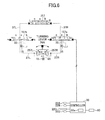
- FIG. 8 is a hydraulic circuit diagram of the hydraulic circuit according to another embodiment.
- the boom lever 26B is operated by an operator.
- the boom lever 26B converts the primary side hydraulic pressure supplied from the pilot line 25 into a secondary side hydraulic pressure in response to the operation applied to the boom lever 26 by the operator.
- the secondary side hydraulic pressure is transmitted to solenoid proportional valves 154a and 154b (switching valves) through pilot lines 27R and 27L, and also transmitted to a flow control valve 154 through pilot lines 37R and 37L.
- the operation device for operating the boom 4 is constituted by the boom lever 26B and remote control valves 254R and 254L.
- the remote control valve 254R is a valve for outputting the pilot pressure, which corresponds to an amount of operation performed on the boom lever 26B in an upward direction or a downward direction, to the flow control valve 154.
- the solenoid proportional valves 154a and 154b are arranged between the boom lever 26B and the flow control valve 154.
- the remote control valves 254R and 254L are connected to the R port of the flow control valve 154 by the pilot lines 27R and 37R via the solenoid proportional valve 154a.
- the remote control valve 254L is connected to the L port of the flow control valve 154 by the pilot lines 27L and 37L via the solenoid proportional valve 154b.
- Each of the remote control valves 257R and 257L receives a pressure of the operating oil supplied by the pilot pump 15 as a primary pressure, and outputs a secondary pressure corresponding to an operation amount of the boom lever 26B as a pilot pressure.
- the pilot pressure input to the flow control valve 154 is switched by the solenoid proportional valves 154a and 154b.
- the solenoid proportional valve 154a is a 4-port 3-position valve.
- a first port of the solenoid proportional valve 154a is connected to the R port of the flow control valve 154 through the pilot line 37R.
- a second port of the solenoid proportional valve 154a is connected to the remote control valve 254R through the pilot line 27R.
- a third port of the solenoid proportional valve 154a is connected to the pilot pump 15 through the pilot line 25.
- a fourth port of the solenoid proportional valve 154a is connected to the tank.
- the solenoid proportional valve 154b is also a 4-port 3-position valve.
- the connection relationship of first port through fourth port is basically the same as the connection relationship of the solenoid proportional valve 154a, and a description thereof will be omitted.
- the flow control valve 154 is switched to the neutral position a so as to avoid a contact between the shovel and an entering object.
- the center bypass pipe path 40R and the hydraulic lines 322A and 322B are set in the non-communicated state to stop the supply of the operating oil to the turning hydraulic motor 21.
- a time period from the deceleration of the upper turning body 3 to the stop of the upper turning body 3 becomes long.
- the solenoid proportional valves 154a and 154b are provided to shorten the time period from the deceleration to the stop of the upper turning body 3.
- the flow of the operating oil from the main pump 14R is automatically switched by switching the flow control valve 154.
- the boom lever 26B is operated in a downward direction and the attachment 125 is brought into contact with a ground. Because a larger braking force is applied to the turning hydraulic motor, the turning operation of the upper turning body 3 can be stopped more quickly.
- the secondary pressure of the operating oil discharged from the pilot pump 15 is supplied to the R port of the flow control valve 154 (refer to FIG. 5 ). If the controller 30 detects an entering object while the upper turning body 3 is turning, the controller 30 switches the solenoid proportional valve 154a based on the control signal of the controller 30. More specifically, the controller 30 switches the solenoid proportional valve 154a from the neutral position a to the left side position c. At this time, the solenoid proportional valve 154b may be maintained at the neutral position a. Thereby, the pilot line 25 is set in the communicated stated with the pilot line 37R, and the pilot line L is set in the communicated state with the pilot line 37R.
- the solenoid proportional valve 154a By switching the solenoid proportional valve 154a from the neutral position to the left side position c, the secondary pressure of the operating oil discharged from the pilot pump 15 is supplied to the R port of the flow control valve 154. Thereby, the center bypass pipe path 40R and the hydraulic line 44B are set in the communicated state with each other, and the discharge side port of the main pump 14R is set in the communicated state with the rod side port of the boom cylinder 7. If the boom lever 26B is not operated by the operator, the L port of the flow control valve 154 is at a low pressure.
- the solenoid proportional valve 154a is switched from the neutral position a to the left side position c, and the solenoid proportional valve 154b is switched from the neutral position a to the right side position b. That is, the pilot line 25 is set in the communicated state with the pilot line 37R, and the pilot line 37L is set in the communicated state with the tank port. Thereby, even if the operator is operating the boom lever 26B in the upward direction, the downward operation of the boom 4 is performed automatically. That is, by providing the solenoid proportional valves 154a and 154b, the operation of the boom 4 can be separated from the operation of the boom lever 26B by the operator.
- the flow of the operating oil from the main pump 14R can be switched to the boom down direction irrespective of or irrelevant to the operation of the boom lever 26B by the operator.
- a large braking force is applied to the turning hydraulic motor 21, which is rotating due to inertia, in a direction opposite to the rotating direction of the turning hydraulic motor 21.
- the braking distance can be shortened by generating a frictional force by the contact between the attachment 125 and the ground in a direction opposite to the turning direction of the upper turning body 3.
- the shovel is avoided from contacting with the entering object.
- the operation amount of the turning lever 26A may change due to a vibration of the shovel. In such a case, there may be a case where the turning operation of the upper turning body 3 does not stop and the turning operation is continued.
- the operation oil is supplied from the main pump 14R to the boom cylinder 7. Then, the solenoid proportional valves 154a and 154b are switched to set the main pump 14R and the rod side port of the boom cylinder 7 in the communicated state with each other. Thereby, the grounding of the attachment 125 is performed, and a large braking force is applied to the turning hydraulic motor 21 in the opposite direction to the rotating direction of the turning hydraulic motor 21.
- the solenoid proportional valves 154a and 154b are switched so as to cause the attachment 125 to be grounded to stop the upper turning body 3.
- the pilot line 25 is set in the communicated state with the pilot line 37R to supply the secondary pressure from the pilot pump 15 to the R port of the flow control valve 154.
- the low control valve 154 is switched, and a hydraulic line 44B connected to the rod side of the boom cylinder 7 is set in the communicated state with the center bypass pipe path 40R. That is, the discharge side port of the main pump 14R is set in the communicated state with the rod side port of the boom cylinder 7.
- the attachment 125 is moved downward and the grounding control is performed irrespective of the operation of the boom lever 26B by the operator depending on the circumstances.
- a large braking force can be generated to the turning hydraulic motor 21 because the flow of the operating oil can be switched by switching the solenoid proportional valves 154a and 154b irrespective of changes in the lever operation amount.
- a control to move the attachment 125 upward can be performed by setting the hydraulic line 44A connected to the head side of the boom cylinder 7 in the communicated state with the center bypass pipe path 40R. Such a control is described later.
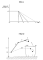
- FIG. 9 is a graph for explaining the control operation of the shovel mounted with the hydraulic circuit illustrated in FIG. 8 .
- a solid line indicates a braking characteristic in a case where a control according to the present embodiment to avoid the attachment 125 from contacting with an entering object is performed.
- a single-dashed chain line indicates a braking characteristic, as a comparison example, in a case where the reverse lever control is performed as a comparison example.
- a dashed line indicates a breaking characteristic, as a comparison example, in a case where the above-mentioned controls are not performed.
- the horizontal axis represents time T
- the vertical axis represents the angular velocity ⁇ of the turning hydraulic motor 21.
- the turning hydraulic motor 21 is continuously turning at a fixed angular velocity ⁇ 0 according to a lever operation by the operator, and, thus, the upper turning body 3 is set in a constant velocity state.
- the control signal is set in an ON state. Specifically, the solenoid proportional valve 154a is switched to the left side position c based on the control signal from the controller 30. Thereby, the flow control valve 154 is switched to the right side position b, and the operating oil from the main pump 14R is supplied to the rode side of the boom cylinder 7. Thus, the downward operation of the boom 4 is stared, and the attachment 125 including the boom 4 is grounded. According to the grounding operation, a frictional force is generated between the attachment 125 and the ground, which the frictional force turns into a braking force to stop the upper turning body 3 from turning. By generating the braking force, as indicated by the solid line in the graph of FIG.
- the angular velocity ⁇ of the turning hydraulic motor 21 decreases after time T1. Because a large frictional force is generated by grounding the attachment 125 by performing the downward operation of the boom 4, the angular velocity ⁇ of the turning hydraulic motor 21 decreases faster than the others as indicated by the solid line in the graph of FIG. 9 , and the upper turning body 3 stops at time T4, which is earlier than time T2 and time T3.
- the time at which the angular velocity ⁇ of the turning hydraulic motor 21 becomes zero is as late as time T3 (refer to the dashed line in the graph of FIG. 9 ).
- the time at which the angular velocity ⁇ of the turning hydraulic motor 21 becomes zero is as early as time T4 (refer to the solid line in the graph of FIG. 9 ).
- the braking force which is generated by grounding the attachment 125 at a high speed by performing the downward operation of the boom 4, is larger than the braking force generated in the embodiment illustrated in FIG. 5 in which the flow of the operating oil in the turning hydraulic motor 21 is switched to generate a braking force in an opposite direction to the turning direction.
- the time at which the angular velocity ⁇ of the turning hydraulic motor 21 becomes zero is as early as time T4 (refer to the solid line in the graph of FIG. 9 ) as compared to the embodiment illustrated in FIG. 5 (refer to the dashed line extending to time T3 in the graph of FIG. 9 ).
- FIG. 10 is an illustration for explaining the control operation of turning the upper turning body 3 of the shovel according to a further embodiment.
- the secondary pressure of the operating oil discharged from the pilot pump 15 is supplied to the L port side of the flow control valve 154.
- the solenoid proportional valve 154b is switched based on the control signal of the controller 30 (refer to FIG. 8 ). More specifically, the solenoid proportional valve 154b is switched from the neutral position a to the left side position c. Then, the pilot line 25 is set in the communicated state with the pilot line 37L to supply the secondary pressure from the pilot pump 15 to the L port of the flow control valve 154.
- the flow control valve 154 is switched, and the hydraulic line 44A, which is connected to the head side of the boom cylinder 7, is set in the communicated state with the center bypass pipe path 40R. That is, the discharge side port of the main pump 14R is set in the communicated state with the head side port of the boom cylinder 7. As a result, the attachment 125 is lifted irrespective of the lever operation by the operator.
- the solenoid proportional valve 154a may be at the neutral position a.
- the solenoid proportional valve 154b By switching the solenoid proportional valve 154b from the neutral position a to the left side position c, the pilot line 25 is set in the communicated state with the pilot line 37L and the pilot line 27R is set in the communicated state with the pilot line 37R.
- the secondary pressure of the operating oil discharged from the pilot pump 15 is supplied to the L port of the flow control valve 154.
- the R port of the flow control valve 154 is at a low pressure.
- the solenoid proportional valve 154a When the boom lever 26B is operated in the downward direction by the operator, the solenoid proportional valve 154a is switched from the neutral position a to the right side positon b and the solenoid proportional valve 154b is switched from the neutral position a to the left side positon c. That is, the pilot line 25 is set in the communicated state with the pilot line 37L and the pilot line 37R is set in the communicated state with the tank port. Thereby, even when the operator is operating the boom lever 26B in the downward direction, the lifting operation of the boom 4 is performed automatically.
- the avoiding control is performed by lifting the attachment 125 irrespective of or irrelevant to the operation of the boom lever 26B by the operator according to the circumstances.
- the lifting operation of the boom 4 is performed by switching the flow control valve to the left side position, which causes the operating oil from the main pump 14R to flow to the head side of the boom cylinder 7 and causes the operating oil from the rod side to the operating oil tank.
- the control signal is turned to an ON state.
- the solenoid proportional valves 154a and 154b are switched based on the control signal from the controller 30.
- the discharge side port of the main pump 14R is set in the communicated state with the head side of the boom cylinder 7 to supply the operating oil from the main pump 14R to the boom cylinder 7.
- the operating oil from the rod side of the boom cylinder 7 is ejected to the operating oil tank, which causes the lifting operation of the boom 4.
- the attachment including the boom 4 is moved in the upward direction.
- the attachment 125 is avoided from contacting with the entering object.
- the lifting operation of the boom 4 is performed automatically according to the control signal from the controller 30.
- the operation of the attachment 125 including the boom 4 can be switched to the upward movement irrespective of the operation of the boom lever 26B by the operator. That is, by providing the solenoid proportional valves 154a and 154b, the operation of the boom 4 is separated from the operation of the boom lever 26B by the operator.
- the shovel is reliably avoided from contacting with the entering object by performing the control operation to move the attachment 125 in the upward direction.
- the attachment 125 can be avoided from contacting with the entering object automatically by switching the solenoid proportional valves 154a and 154b irrespective of the change in the operation amount of the lever.
- the controller 30 determines that an entering object enters the monitoring areas 18a, 18b and 18c. If it is determined by the controller 30 that an entering object enters the monitoring areas 18a, 18b and 18c, the operating oil is supplied from the main pump 14R to the boom cylinder 17. Then, the main pump 14R is set in the communicated state with the head side port of the boom cylinder 7 by switching the solenoid proportional valves 154a and 154b. Thereby, the lifting operation of the attachment 125 is performed, which permits the attachment 125 to avoid from contacting with the entering object.
- the solenoid proportional valves 154a and 154b are set in the communicated state so that the grounding control of the attachment 125 or the avoid control of the attachment 125 is performed. That is, the discharge side port of the pilot pump 15 is set in the communicated state with any one of the ports of the flow control valve 154. Thereby, the switching operation of the flow control valve 154 is performed.
- FIG. 11 is an illustration for explaining a turning mechanism of the shovel according to an embodiment different from that of FIG. 7 .
- the turning operation of the upper turning body 3 in the shovel according to the present embodiment is achieved by causing an inner tooth gear 61, which is fixed to the lower running body 1, to be engaged with a turning pinion 62, which is incorporated in the upper turning body 3.
- an inner race 63 is driven by the turning pinion 62 via the inner tooth gear 61 at a low speed and high-torque.
- a turning frame 3a is rotated together with an outer race about the turning center 11, which causes the upper turning body 3 to perform the turning operation.
- the inner race 63 and an outer race 64 are arranged to make concentric circles with respect to the turning center 111 of the upper turning body 3. More specifically, the turning pinion 62 is engaged with the inner tooth gear 61 formed on the inner periphery of the inner race 63, and the inner tooth gear 61 is fixed to the turning frame 3a.
- the upper turning body 3 performs a turning operation by the turning pinion 62 moving along the inner periphery of the inner race 63.
- the motion of the inner race 63 is stopped to forcibly stop (lock) the upper turning body 3.
- the upper turning body 3 is stopped urgently, which permits reliable avoiding of the shovel from contacting with the entering object even if there is a high-possibility of contact with the entering object.
- the above-mentioned control operation is referred to as the "pin insertion control”.
- FIG. 12 is a graph for explaining a control operation of the shovel equipped with the turning mechanism illustrated in FIG. 11 .
- a solid line indicates a braking characteristic of the pin insertion control in the shovel according to the present embodiment.
- a single-dashed chain line indicates, as a comparison example, a braking characteristic, when the reverse lever control is performed.
- a double-dashed chain line indicates, as a comparison example, a braking characteristic when the grounding control of the attachment is performed.
- a dashed line indicates, as a comparison example, a braking characteristic, when the above-mentioned control is not performed.
- the vertical axis represents time T
- the horizontal axis represents the angular velocity ⁇ of the turning hydraulic motor 21.
- the upper turning body 3 continuously turns at a constant angular velocity ⁇ 0, and the upper turning body 3 is in a constant speed state.
- the control signal is turned to an ON state. Specifically, the pin 60 is inserted into the inner tooth gear 61 base on the control signal from the controller 30. Because the turning pinion 62 is locked by the pin 60 being inserted into the inner tooth gear 61, the drive of the inner race 63 is stopped, and, thereby, the upper turning body 3 is stopped. As a result, if it is determined by the controller 30 that an entering object enters the monitoring areas 18a, 18b and 18c, the pin insertion control is performed irrespective of the operation of the boom lever 26B by the operator according to the circumstances. According to the present embodiment, the upper turning body 3 is stopped simultaneously with the control signal being turned to the ON state.
- the upper turning body 3 is stopped much faster than the case where the turning lever 26A is returned to the neutral position so as to cause the turning hydraulic motor 21 to generate a braking force (refer to the dashed line in the figure).
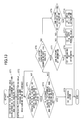
- FIG. 13 is a flowchart of a control process performed by the shovel according to the present embodiment.
- the first monitoring area 18a, second monitoring area 18b and third monitoring area 18c are determined based on the position of the attachment 125 and the angular velocities ⁇ , ⁇ ', ⁇ " of the upper turning body 3 in a controlling part 30a of the controller 30 (step ST1). Further, the controller computes the height from the swing center 112 to the tip of the bucket 6, the attachment length R, and the radiuses R and R" based on the results of measurement input from the angle sensors 22A and 22B and the stroke sensor 22C.
- the monitoring angle upper limit value ⁇ d (refer to FIG. 3 ) is set larger as the angular velocity ⁇ becomes larger. Moreover, if the angular velocity ⁇ is constant, it is desirous to set the monitoring angle upper limit ⁇ d larger as the attachment length R becomes longer. This is because the moment of inertia acted on the shovel becomes large.
- the radius R' of the second monitoring area 18b is fixed. It is desirous to set the monitoring angle upper limit value ⁇ d (refer to FIG. 3 ) larger as the angular velocity ⁇ ' becomes larger. Similarly, because the radius R" of the third monitoring area 18c is fixed, it is desirous to set the monitoring angle upper limit value ⁇ d larger as the angular velocity ⁇ " becomes larger.
- the sizes of the monitoring areas 18a, 18b and 18c are determined.
- the type of the entering object is identified by analyzing image data input from the entering object detection device 80.
- the identification is performed by changing the light-emitting color of the transmitter 222 attached to the entering object in response to the type of the entering object.
- the determining part 30a of the controller 30 determines the control operation of the upper turning body 3 or the attachment 125 based on the thus-calculated monitoring areas 18a, 18b and 18c and the type and positional relationship of the entering object.
- the controller determines whether a possibility of contact (abutment) of the entering object with the shovel is high so as to determine the control operation of the upper turning body 3 or the attachment 125 to be used.
- the controller determines which one of the monitoring areas the entering object enters. This determination is performed by the determining part 30a of the controller 30 based on the image data of the entering object detection device 80.
- an entering object enters one of the monitoring areas, for example, an alarm lamp is turned on or blinked, and sound an alarm buzzer (step ST2).
- the type of alarming may be changed for each emergency area.
- the determining part 30a determines a degree of risk (degree of emergency) of the entering object being contacted with a drive part including the upper turning body 3 and the attachment 125 (step ST3). According to the degree of risk, the controller 30 determines the avoid control to avoid the drive part from contacting with the entering object.
- the determining 30a determines a distance between the entering object and the attachment 125 or the upper turning body. 3.
- the determining part 30a determines whether a distance between the attachment 125 and the entering object and a distance between the upper turning body 3 and the entering object are larger than a predetermined distance. If it is determined in step ST 4 that each distance is larger than the predetermined distance (YES in step ST4), the controller 30 performs the "reverse lever control" (step ST5). The stop operation of the upper turning body 3 is performed by reversing the flow of the operating oil circulating through the turning hydraulic motor 21.
- step ST6 If it is determined in step ST4 that either one of the distances is not larger than the predetermined distance (NO in step ST4), it is determined whether a distance between the counter weight of the upper turning body 3 and the entering object is longer than the predetermined distance (step ST6). That is, it is determine in step ST6 whether the upper turning body 3 or the attachment 125 can avoid from contacting with the entering object by performing the above-mentioned other control operations when there is no room in the distance to cope with the "reverse lever control".
- step ST6 If it is determined in step ST6 that the distance is longer than the predetermined distance (NO in step ST6), it is determined whether the contact can be avoided by lifting the attachment 125 (step ST9). If it is determined in step ST9 that the contact can be avoided by lifting the attachment 125 (Yes in step ST9), the "avoid control of the attachment 125" is performed (step ST10).
- step ST6 determines whether the distance is not longer than the predetermined distance (YES in step ST6). If it is determined in step ST7 that the contact can be avoided by the grounding (YES in step ST7), the grounding control of the attachment 125" is performed (step ST8).
- the "pin insertion control” is performed to forcibly stop the turning operation of the upper turning body 3 (step ST11).
- the hydraulic circuits of the the turning lever and the boom lever is illustrated and explained individually as a hydraulic circuit for performing switching of the flow control valve by solenoid proportional valves.
- the present invention is not limited to such as structure.
- both the flow control valves of the hydraulic circuits of the turning lever and the boom lever may be switched by the respective solenoid proportional valves.
- both the flow control valves of the hydraulic circuits of the boom lever and the arm lever may be switched by the respective solenoid proportional valves.
- all of the flow control valves of the hydraulic circuits of the boom lever, the arm lever and the bucket lever may be switched by the respective solenoid proportional valves.
- the hydraulic circuit of the arm lever causes the operating oil to be supplied to the R port of the flow control valve 155 by switching the solenoid valve 155a to the left side position c by the controller 30.
- the flow control valve 155 is switched to the right side position b, which causes the operating oil to be supplied from the main pump 14L to the head side of the arm cylinder 8 (refer to FIG. 5 ).
- the lifting operation of the arm 5 is automatically (forcibly) performed.
- the flow control valve 155 is switched to the left side position c by switching the solenoid proportional valve 155b to the left side position c by the controller 30.
- the hydraulic circuit of the bucket lever causes the operating oil to be supplied to the R port of the flow control valve 158 by switching the solenoid valve 158a to the left side position c by the controller 30.
- the flow control valve 158 is switched to the right side position b, which causes the operating oil to be supplied from the main pump 14R to the head side of the bucket cylinder 9 (refer to FIG. 5 ).
- the opening operation of the bucket 6 is automatically (forcibly) performed.
- the flow control valve 158 is switched to the left side position c by switching the solenoid proportional valve 158b to the left side position c by the controller 30.
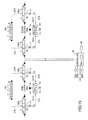
- FIGS. 14 through 16 The operation of the hydraulic circuits illustrated in FIGS. 14 through 16 are basically the same as the hydraulic circuits of the turning lever 26A and the boom lever 26B, and the descriptions thereof will be omitted.
- a braking may be applied to the upper turning body 3 by a mechanical brake 23 (refer to FIG. 5 ). Specifically, the mechanical brake 23 is released, while the upper turning body 3 is turning, by supplying the operating oil from the pilot pump 15 into the cylinder 23e. Then, the control signal is sent from the controller 30 in response to the degree of risk (urgency) of contact to switch the solenoid valve 50.
- control operations may be performed individually or some control operations may be combined. Thereby, the upper turning body 3 or the attachment 125 and the entering object are avoided from contacting with each other in response to various circumstances.
- the structure of the shovel according to the present invention is not limited to that illustrated in FIG. 2 in which the turning hydraulic motor is used as a turning motor.
- the present invention can be achieved using a turning electric motor as illustrated in FIG 17 .
- double lines denote a mechanical drive system
- bold solid lines denote high-pressure hydraulic lines
- thin dashed lines denote pilot lines
- bold dotted lines denote electric drive/control lines.
- the shovel illustrated in FIG. 17 uses an electrically operated turning mechanism 2, and is provided with a turning electric motor 210 for driving the turning mechanism 2.
- the turning electric motor 210 as an electric operation element is connected to an electricity accumulation system 120 through an inverter 20.
- a resolver 220, the mechanical brake 23 and a turning transmission 24 are connected to the rotation axis 210A of the turning electric motor 210.
- the turning electric motor 210, inverter 20, resolver 220, mechanical brake and turning transmission together constitute a load drive system.
- the electricity accumulation system 120 including an electricity accumulator is connected to a motor generator 12 via an inverter 18A.
- the electricity accumulation system 120 is constituted by a voltage up-down converter connected by the inverters 18A and 20 and a direct current line and the electricity accumulator connected to the voltage up-down converter.
- a capacitor is used as the electricity accumulator.
- a rechargeable secondary battery such as a lithium ion battery, a lithium ion capacitor or an electricity exchangeable power source of other forms may be used as the electricity accumulator.
- the engine 11 is provided with a starter motor 11a and a battery 11b for starting the starter motor 11a.
- the battery 11b is a battery generally used for a vehicle, and is, for example, a 24V lead storage battery.
- the shovel illustrated in FIG. 17 can provide the same action and effect as the shovel using the turning hydraulic motor 21.
- an electric lever which generates an electric signal and sends the electric signal from the controller to the flow control valves 154, 155, 157 and 158, may be used other than the operation levers.
- the operation amount of the electric lever is input to the controller, and, thereafter, the electric signal corresponding to the operation amount is sent to the flow control valve to control the flow control valve.
- the controller detects an entering object, the electric signal sent from the controller is switched from the electric signal corresponding to the operation amount to the electric signal generated based on previously input signal patterns.
- the flow control valve is controlled base on the previously input signal patterns.
- the present invention is not limited to the use of the xyz-coordinated system.
- the coordinate may be defined by latitude and altitude using a global reference coordinate system. This is effective for a case where a position of an entering object is measured by GPS.
Landscapes
- Engineering & Computer Science (AREA)
- General Engineering & Computer Science (AREA)
- Mining & Mineral Resources (AREA)
- Civil Engineering (AREA)
- Structural Engineering (AREA)
- Mechanical Engineering (AREA)
- Radar, Positioning & Navigation (AREA)
- Remote Sensing (AREA)
- Operation Control Of Excavators (AREA)
- Component Parts Of Construction Machinery (AREA)
Applications Claiming Priority (1)
| Application Number | Priority Date | Filing Date | Title |
|---|---|---|---|
| JP2014067213A JP6962667B2 (ja) | 2014-03-27 | 2014-03-27 | ショベル及びその制御方法 |
Publications (3)
| Publication Number | Publication Date |
|---|---|
| EP2924182A2 true EP2924182A2 (fr) | 2015-09-30 |
| EP2924182A3 EP2924182A3 (fr) | 2016-03-02 |
| EP2924182B1 EP2924182B1 (fr) | 2020-05-06 |
Family
ID=52706065
Family Applications (1)
| Application Number | Title | Priority Date | Filing Date |
|---|---|---|---|
| EP15160438.6A Active EP2924182B1 (fr) | 2014-03-27 | 2015-03-24 | Pelleteuse et son procédé de contrôle |
Country Status (5)
| Country | Link |
|---|---|
| US (2) | US10072395B2 (fr) |
| EP (1) | EP2924182B1 (fr) |
| JP (1) | JP6962667B2 (fr) |
| KR (1) | KR102301844B1 (fr) |
| CN (3) | CN104963373B (fr) |
Cited By (3)
| Publication number | Priority date | Publication date | Assignee | Title |
|---|---|---|---|---|
| CN106545041A (zh) * | 2015-11-06 | 2017-03-29 | 徐工集团工程机械股份有限公司 | 液压控制系统和挖掘机 |
| EP3399109A4 (fr) * | 2015-12-28 | 2018-12-26 | Sumitomo (S.H.I.) Construction Machinery Co., Ltd. | Excavateur |
| EP3767044A4 (fr) * | 2018-04-26 | 2021-08-18 | Kobelco Construction Machinery Co., Ltd. | Dispositif de commande de pivot pour machine de travail du type pivotant |
Families Citing this family (24)
| Publication number | Priority date | Publication date | Assignee | Title |
|---|---|---|---|---|
| WO2014051170A1 (fr) * | 2012-09-25 | 2014-04-03 | Volvo Construction Equipment Ab | Système de gradation automatique pour un engin de chantier et son procédé de commande |
| CN107208397B (zh) * | 2014-12-24 | 2020-04-07 | 沃尔沃建筑设备公司 | 建筑设备的回转控制装置及其控制方法 |
| US10344450B2 (en) * | 2015-12-01 | 2019-07-09 | The Charles Machine Works, Inc. | Object detection system and method |
| JP6468444B2 (ja) * | 2016-04-28 | 2019-02-13 | コベルコ建機株式会社 | 建設機械 |
| JP7027402B2 (ja) * | 2016-07-20 | 2022-03-01 | プリノート エル.ティー.ディー. | 回転式上部構造を有する履帯車両及び履帯車両用プロセス |
| KR102426644B1 (ko) * | 2016-12-06 | 2022-07-27 | 스미토모 겐키 가부시키가이샤 | 건설기계 |
| JP6822134B2 (ja) * | 2016-12-22 | 2021-01-27 | コベルコ建機株式会社 | 建設機械 |
| EP3680397B1 (fr) * | 2017-09-07 | 2023-08-09 | Hitachi Construction Machinery Co., Ltd. | Machine de construction |
| JP7474192B2 (ja) * | 2018-03-23 | 2024-04-24 | 住友重機械工業株式会社 | ショベル |
| CN111919003A (zh) * | 2018-03-26 | 2020-11-10 | 住友建机株式会社 | 挖土机 |
| KR102575201B1 (ko) * | 2018-03-28 | 2023-09-06 | 스미토모 겐키 가부시키가이샤 | 쇼벨 |
| CN109914517B (zh) * | 2019-03-26 | 2022-03-11 | 吉林大学 | 一种挖掘机智能回转节能控制系统 |
| CN113631776B (zh) * | 2019-03-28 | 2023-02-17 | 住友建机株式会社 | 挖土机及施工系统 |
| JP7189074B2 (ja) * | 2019-04-26 | 2022-12-13 | 日立建機株式会社 | 作業機械 |
| EP4012110B1 (fr) * | 2019-08-05 | 2024-04-17 | Sumitomo Heavy Industries, Ltd. | Excavatrice |
| JP7268579B2 (ja) * | 2019-11-01 | 2023-05-08 | コベルコ建機株式会社 | 油圧作業機及び遠隔操縦システム |
| WO2021131761A1 (fr) * | 2019-12-27 | 2021-07-01 | 日立建機株式会社 | Engin de chantier |
| JP7080947B2 (ja) * | 2020-09-30 | 2022-06-06 | 住友建機株式会社 | ショベル |
| JP7500460B2 (ja) * | 2021-02-17 | 2024-06-17 | 株式会社クボタ | 作業機 |
| JPWO2022202674A1 (fr) * | 2021-03-22 | 2022-09-29 | ||
| US11987961B2 (en) | 2021-03-29 | 2024-05-21 | Joy Global Surface Mining Inc | Virtual field-based track protection for a mining machine |
| US11939748B2 (en) | 2021-03-29 | 2024-03-26 | Joy Global Surface Mining Inc | Virtual track model for a mining machine |
| WO2022208974A1 (fr) * | 2021-03-29 | 2022-10-06 | 日立建機株式会社 | Engin de chantier |
| CN115450278B (zh) * | 2022-09-16 | 2023-09-22 | 江苏电子信息职业学院 | 一种装载机铲斗辅助铲掘控制方法 |
Family Cites Families (34)
| Publication number | Priority date | Publication date | Assignee | Title |
|---|---|---|---|---|
| JP2597385B2 (ja) * | 1988-04-22 | 1997-04-02 | ヤンマーディーゼル株式会社 | 作業機の危険領域回避装置 |
| JPH0794737B2 (ja) * | 1989-08-02 | 1995-10-11 | 株式会社小松製作所 | 油圧掘削機における直線掘削制御装置 |
| JP2700710B2 (ja) * | 1990-06-21 | 1998-01-21 | 新キャタピラー三菱株式会社 | 建設機械の警報装置 |
| JP2910355B2 (ja) | 1991-09-05 | 1999-06-23 | 油谷重工株式会社 | 建設機械の安全装置 |
| JPH05112973A (ja) | 1991-10-23 | 1993-05-07 | Nippon Telegr & Teleph Corp <Ntt> | 建設機械およびその制御方法 |
| JP2753777B2 (ja) | 1991-10-24 | 1998-05-20 | 株式会社フジタ | 建設作業車の自動制御装置 |
| JP2548978Y2 (ja) | 1992-01-30 | 1997-09-24 | 新キャタピラー三菱株式会社 | 建設機械の安全装置 |
| JP3215502B2 (ja) | 1992-05-19 | 2001-10-09 | 株式会社小松製作所 | 作業機動作範囲制限装置 |
| JPH0640066U (ja) | 1992-10-27 | 1994-05-27 | 住友建機株式会社 | 建設機械の作業安全装置 |
| JP3434514B2 (ja) * | 1993-03-23 | 2003-08-11 | 日立建機株式会社 | 油圧作業機の油圧駆動装置 |
| DE69511033T2 (de) * | 1994-04-28 | 2000-02-17 | Hitachi Construction Machinery Co., Ltd. | Baggersteuervorrichtung mit einem baggerbereich-begrenzer für baumaschinen |
| EP0990739A4 (fr) * | 1998-03-18 | 2002-11-05 | Hitachi Construction Machinery | Excavatrice a commande automatique et systeme concasseur de pierres la comportant |
| JP2002179387A (ja) * | 2000-10-03 | 2002-06-26 | Komatsu Ltd | 作業用車両の速度制御装置とその速度制御方法 |
| JP2003105807A (ja) * | 2001-09-27 | 2003-04-09 | Komatsu Ltd | 作業車両の侵入禁止領域での停止制御方法及びその制御装置 |
| JP3902085B2 (ja) | 2002-07-15 | 2007-04-04 | 日立建機株式会社 | 建設機械の旋回制御装置 |
| JP3946214B2 (ja) | 2004-09-30 | 2007-07-18 | 大林道路株式会社 | 油圧式走行装置の緊急停止装置 |
| FR2917559B1 (fr) * | 2007-06-12 | 2009-12-25 | Centre Nat Rech Scient | Capteur d'images numeriques,procede d'acquisition et de reconstruction d'images,et systeme de mise en oeuvre |
| JP4678604B2 (ja) * | 2007-08-01 | 2011-04-27 | Smc株式会社 | 真空発生ユニット |
| KR20090103088A (ko) * | 2008-03-27 | 2009-10-01 | (주)내경엔지니어링 | 굴삭기의 안전 조종 제어 방법 및 그 장치 |
| KR101551980B1 (ko) * | 2008-12-23 | 2015-09-09 | 두산인프라코어 주식회사 | 건설장비에 있어서 장애물 회피 제어 장치 |
| JP2011052383A (ja) | 2009-08-31 | 2011-03-17 | Caterpillar Sarl | 作業機械の旋回制御装置 |
| EP2631374B1 (fr) * | 2010-10-22 | 2020-09-30 | Hitachi Construction Machinery Co., Ltd. | Dispositif de contrôle périphérique de machine de travail |
| KR101768662B1 (ko) * | 2011-03-08 | 2017-08-17 | 스미토모 겐키 가부시키가이샤 | 쇼벨 및 쇼벨의 제어방법 |
| JP5665652B2 (ja) * | 2011-05-19 | 2015-02-04 | 日立建機株式会社 | 建設機械の情報管理装置 |
| JP6270029B2 (ja) * | 2011-05-26 | 2018-01-31 | 住友重機械工業株式会社 | 電動式旋回装置を備えたショベル及びその制御方法 |
| JP5653844B2 (ja) * | 2011-06-07 | 2015-01-14 | 住友建機株式会社 | ショベル |
| JP5899877B2 (ja) | 2011-06-17 | 2016-04-06 | 日本ケミコン株式会社 | コンデンサおよびその製造方法 |
| WO2013005809A1 (fr) * | 2011-07-06 | 2013-01-10 | 住友重機械工業株式会社 | Pelleteuse et procédé de commande de pelleteuse |
| EP2792798B1 (fr) | 2011-12-13 | 2018-02-21 | Volvo Construction Equipment AB | Dispositif de détection de danger omnidirectionnel pour appareil de construction |
| JP5859857B2 (ja) * | 2012-01-20 | 2016-02-16 | コベルコ建機株式会社 | 建設機械の油圧回路 |
| EP2808455B1 (fr) * | 2012-01-27 | 2018-05-30 | Doosan Infracore Co., Ltd. | Dispositif améliorant la stabilité de fonctionnement d'engins de chantier |
| JP2013189767A (ja) | 2012-03-13 | 2013-09-26 | Sumitomo Heavy Ind Ltd | 電動式旋回装置 |
| US9598836B2 (en) * | 2012-03-29 | 2017-03-21 | Harnischfeger Technologies, Inc. | Overhead view system for a shovel |
| CN102605814B (zh) * | 2012-04-24 | 2014-06-11 | 河北工业大学 | 一种挖掘机工作装置旋转机构 |
-
2014
- 2014-03-27 JP JP2014067213A patent/JP6962667B2/ja active Active
-
2015
- 2015-03-16 KR KR1020150035852A patent/KR102301844B1/ko active Active
- 2015-03-19 CN CN201510122593.3A patent/CN104963373B/zh not_active Expired - Fee Related
- 2015-03-19 US US14/662,435 patent/US10072395B2/en active Active
- 2015-03-19 CN CN202010235451.9A patent/CN111411659B/zh active Active
- 2015-03-19 CN CN202010235438.3A patent/CN111395442B/zh active Active
- 2015-03-24 EP EP15160438.6A patent/EP2924182B1/fr active Active
-
2018
- 2018-08-09 US US16/059,438 patent/US20180347151A1/en not_active Abandoned
Non-Patent Citations (1)
| Title |
|---|
| None |
Cited By (7)
| Publication number | Priority date | Publication date | Assignee | Title |
|---|---|---|---|---|
| CN106545041A (zh) * | 2015-11-06 | 2017-03-29 | 徐工集团工程机械股份有限公司 | 液压控制系统和挖掘机 |
| CN106545041B (zh) * | 2015-11-06 | 2018-10-16 | 徐工集团工程机械股份有限公司 | 液压控制系统和挖掘机 |
| EP3399109A4 (fr) * | 2015-12-28 | 2018-12-26 | Sumitomo (S.H.I.) Construction Machinery Co., Ltd. | Excavateur |
| US10781574B2 (en) | 2015-12-28 | 2020-09-22 | Sumitomo (S.H.I) Construction Machinery Co, Ltd. | Shovel |
| US11434624B2 (en) | 2015-12-28 | 2022-09-06 | Sumitomo(S.H.I) Construction Machinery Co., Ltd. | Shovel |
| EP3767044A4 (fr) * | 2018-04-26 | 2021-08-18 | Kobelco Construction Machinery Co., Ltd. | Dispositif de commande de pivot pour machine de travail du type pivotant |
| US11873620B2 (en) | 2018-04-26 | 2024-01-16 | Kobelco Construction Machinery Co., Ltd. | Turning control apparatus for turning-type working machine |
Also Published As
| Publication number | Publication date |
|---|---|
| CN104963373A (zh) | 2015-10-07 |
| JP2015190159A (ja) | 2015-11-02 |
| JP6962667B2 (ja) | 2021-11-05 |
| US10072395B2 (en) | 2018-09-11 |
| KR20150112803A (ko) | 2015-10-07 |
| EP2924182A3 (fr) | 2016-03-02 |
| CN111395442A (zh) | 2020-07-10 |
| CN111395442B (zh) | 2024-01-09 |
| US20150275483A1 (en) | 2015-10-01 |
| EP2924182B1 (fr) | 2020-05-06 |
| KR102301844B1 (ko) | 2021-09-14 |
| CN111411659B (zh) | 2022-11-15 |
| US20180347151A1 (en) | 2018-12-06 |
| CN104963373B (zh) | 2020-04-28 |
| CN111411659A (zh) | 2020-07-14 |
Similar Documents
| Publication | Publication Date | Title |
|---|---|---|
| EP2924182B1 (fr) | Pelleteuse et son procédé de contrôle | |
| JP7080947B2 (ja) | ショベル | |
| US8701818B2 (en) | Work vehicle and control method for work vehicle | |
| EP3748090A1 (fr) | Véhicule de travail | |
| CN116917586B (zh) | 作业机械以及作业机械的控制方法 | |
| CN114127370B (zh) | 作业机械以及作业机械的控制方法 | |
| JP2014218849A (ja) | 建設機械の動作制限装置 | |
| US20220282459A1 (en) | Operation Assistance System for Work Machine | |
| JP6483302B2 (ja) | ショベル | |
| EP2762645A2 (fr) | Machine mobile, système de freinage et procédé de commande de machine mobile | |
| JP2739358B2 (ja) | 作業機干渉回避装置 | |
| US20180231118A1 (en) | Work machine | |
| JP7032287B2 (ja) | ショベル | |
| CN118696158A (zh) | 周边监视系统及施工机械 | |
| JP7527168B2 (ja) | 作業機械 | |
| JP6822134B2 (ja) | 建設機械 | |
| JP7012041B2 (ja) | ホイール式油圧ショベル | |
| RU2518112C1 (ru) | Способ управления гидравлическим тормозным приводом для обеспечения автоматического торможения автомобиля | |
| JP2026043466A (ja) | 作業機械および作業機械の制御方法 | |
| WO2026048527A1 (fr) | Engin de chantier et procédé de commande d'engin de chantier | |
| US20240209590A1 (en) | Shovel | |
| JP7500297B2 (ja) | ショベル | |
| JP2024141724A (ja) | 作業機械の制御装置 | |
| US20250137237A1 (en) | System and method for controlling work machine | |
| JP2026046360A (ja) | 作業機械の自動旋回制御システム、作業機械、および作業機械の自動旋回制御方法 |
Legal Events
| Date | Code | Title | Description |
|---|---|---|---|
| PUAI | Public reference made under article 153(3) epc to a published international application that has entered the european phase |
Free format text: ORIGINAL CODE: 0009012 |
|
| 17P | Request for examination filed |
Effective date: 20150324 |
|
| AK | Designated contracting states |
Kind code of ref document: A2 Designated state(s): AL AT BE BG CH CY CZ DE DK EE ES FI FR GB GR HR HU IE IS IT LI LT LU LV MC MK MT NL NO PL PT RO RS SE SI SK SM TR |
|
| AX | Request for extension of the european patent |
Extension state: BA ME |
|
| PUAL | Search report despatched |
Free format text: ORIGINAL CODE: 0009013 |
|
| AK | Designated contracting states |
Kind code of ref document: A3 Designated state(s): AL AT BE BG CH CY CZ DE DK EE ES FI FR GB GR HR HU IE IS IT LI LT LU LV MC MK MT NL NO PL PT RO RS SE SI SK SM TR |
|
| AX | Request for extension of the european patent |
Extension state: BA ME |
|
| RIC1 | Information provided on ipc code assigned before grant |
Ipc: F16P 3/14 20060101ALI20160122BHEP Ipc: F16P 3/12 20060101ALI20160122BHEP Ipc: E02F 9/26 20060101ALI20160122BHEP Ipc: E02F 9/20 20060101AFI20160122BHEP Ipc: E02F 3/43 20060101ALI20160122BHEP Ipc: E02F 9/22 20060101ALI20160122BHEP |
|
| 17Q | First examination report despatched |
Effective date: 20160216 |
|
| RBV | Designated contracting states (corrected) |
Designated state(s): AL AT BE BG CH CY CZ DE DK EE ES FI FR GB GR HR HU IE IS IT LI LT LU LV MC MK MT NL NO PL PT RO RS SE SI SK SM TR |
|
| STAA | Information on the status of an ep patent application or granted ep patent |
Free format text: STATUS: EXAMINATION IS IN PROGRESS |
|
| REG | Reference to a national code |
Ref country code: DE Ref legal event code: R079 Ref document number: 602015051994 Country of ref document: DE Free format text: PREVIOUS MAIN CLASS: E02F0009260000 Ipc: E02F0009200000 |
|
| RIC1 | Information provided on ipc code assigned before grant |
Ipc: E02F 9/22 20060101ALI20190930BHEP Ipc: E02F 3/43 20060101ALI20190930BHEP Ipc: F16P 3/14 20060101ALI20190930BHEP Ipc: F16P 3/12 20060101ALI20190930BHEP Ipc: E02F 9/12 20060101ALI20190930BHEP Ipc: E02F 9/26 20060101ALI20190930BHEP Ipc: E02F 9/20 20060101AFI20190930BHEP |
|
| GRAP | Despatch of communication of intention to grant a patent |
Free format text: ORIGINAL CODE: EPIDOSNIGR1 |
|
| STAA | Information on the status of an ep patent application or granted ep patent |
Free format text: STATUS: GRANT OF PATENT IS INTENDED |
|
| INTG | Intention to grant announced |
Effective date: 20191108 |
|
| GRAS | Grant fee paid |
Free format text: ORIGINAL CODE: EPIDOSNIGR3 |
|
| GRAA | (expected) grant |
Free format text: ORIGINAL CODE: 0009210 |
|
| STAA | Information on the status of an ep patent application or granted ep patent |
Free format text: STATUS: THE PATENT HAS BEEN GRANTED |
|
| AK | Designated contracting states |
Kind code of ref document: B1 Designated state(s): AL AT BE BG CH CY CZ DE DK EE ES FI FR GB GR HR HU IE IS IT LI LT LU LV MC MK MT NL NO PL PT RO RS SE SI SK SM TR |
|
| REG | Reference to a national code |
Ref country code: GB Ref legal event code: FG4D |
|
| REG | Reference to a national code |
Ref country code: AT Ref legal event code: REF Ref document number: 1266920 Country of ref document: AT Kind code of ref document: T Effective date: 20200515 Ref country code: CH Ref legal event code: EP |
|
| REG | Reference to a national code |
Ref country code: IE Ref legal event code: FG4D |
|
| REG | Reference to a national code |
Ref country code: DE Ref legal event code: R096 Ref document number: 602015051994 Country of ref document: DE |
|
| REG | Reference to a national code |
Ref country code: LT Ref legal event code: MG4D |
|
| REG | Reference to a national code |
Ref country code: NL Ref legal event code: MP Effective date: 20200506 |
|
| PG25 | Lapsed in a contracting state [announced via postgrant information from national office to epo] |
Ref country code: NO Free format text: LAPSE BECAUSE OF FAILURE TO SUBMIT A TRANSLATION OF THE DESCRIPTION OR TO PAY THE FEE WITHIN THE PRESCRIBED TIME-LIMIT Effective date: 20200806 Ref country code: GR Free format text: LAPSE BECAUSE OF FAILURE TO SUBMIT A TRANSLATION OF THE DESCRIPTION OR TO PAY THE FEE WITHIN THE PRESCRIBED TIME-LIMIT Effective date: 20200807 Ref country code: SE Free format text: LAPSE BECAUSE OF FAILURE TO SUBMIT A TRANSLATION OF THE DESCRIPTION OR TO PAY THE FEE WITHIN THE PRESCRIBED TIME-LIMIT Effective date: 20200506 Ref country code: IS Free format text: LAPSE BECAUSE OF FAILURE TO SUBMIT A TRANSLATION OF THE DESCRIPTION OR TO PAY THE FEE WITHIN THE PRESCRIBED TIME-LIMIT Effective date: 20200906 Ref country code: FI Free format text: LAPSE BECAUSE OF FAILURE TO SUBMIT A TRANSLATION OF THE DESCRIPTION OR TO PAY THE FEE WITHIN THE PRESCRIBED TIME-LIMIT Effective date: 20200506 Ref country code: PT Free format text: LAPSE BECAUSE OF FAILURE TO SUBMIT A TRANSLATION OF THE DESCRIPTION OR TO PAY THE FEE WITHIN THE PRESCRIBED TIME-LIMIT Effective date: 20200907 Ref country code: LT Free format text: LAPSE BECAUSE OF FAILURE TO SUBMIT A TRANSLATION OF THE DESCRIPTION OR TO PAY THE FEE WITHIN THE PRESCRIBED TIME-LIMIT Effective date: 20200506 |
|
| PG25 | Lapsed in a contracting state [announced via postgrant information from national office to epo] |
Ref country code: LV Free format text: LAPSE BECAUSE OF FAILURE TO SUBMIT A TRANSLATION OF THE DESCRIPTION OR TO PAY THE FEE WITHIN THE PRESCRIBED TIME-LIMIT Effective date: 20200506 Ref country code: BG Free format text: LAPSE BECAUSE OF FAILURE TO SUBMIT A TRANSLATION OF THE DESCRIPTION OR TO PAY THE FEE WITHIN THE PRESCRIBED TIME-LIMIT Effective date: 20200806 Ref country code: RS Free format text: LAPSE BECAUSE OF FAILURE TO SUBMIT A TRANSLATION OF THE DESCRIPTION OR TO PAY THE FEE WITHIN THE PRESCRIBED TIME-LIMIT Effective date: 20200506 Ref country code: HR Free format text: LAPSE BECAUSE OF FAILURE TO SUBMIT A TRANSLATION OF THE DESCRIPTION OR TO PAY THE FEE WITHIN THE PRESCRIBED TIME-LIMIT Effective date: 20200506 |
|
| REG | Reference to a national code |
Ref country code: AT Ref legal event code: MK05 Ref document number: 1266920 Country of ref document: AT Kind code of ref document: T Effective date: 20200506 |
|
| PG25 | Lapsed in a contracting state [announced via postgrant information from national office to epo] |
Ref country code: NL Free format text: LAPSE BECAUSE OF FAILURE TO SUBMIT A TRANSLATION OF THE DESCRIPTION OR TO PAY THE FEE WITHIN THE PRESCRIBED TIME-LIMIT Effective date: 20200506 Ref country code: AL Free format text: LAPSE BECAUSE OF FAILURE TO SUBMIT A TRANSLATION OF THE DESCRIPTION OR TO PAY THE FEE WITHIN THE PRESCRIBED TIME-LIMIT Effective date: 20200506 |
|
| PG25 | Lapsed in a contracting state [announced via postgrant information from national office to epo] |
Ref country code: DK Free format text: LAPSE BECAUSE OF FAILURE TO SUBMIT A TRANSLATION OF THE DESCRIPTION OR TO PAY THE FEE WITHIN THE PRESCRIBED TIME-LIMIT Effective date: 20200506 Ref country code: AT Free format text: LAPSE BECAUSE OF FAILURE TO SUBMIT A TRANSLATION OF THE DESCRIPTION OR TO PAY THE FEE WITHIN THE PRESCRIBED TIME-LIMIT Effective date: 20200506 Ref country code: EE Free format text: LAPSE BECAUSE OF FAILURE TO SUBMIT A TRANSLATION OF THE DESCRIPTION OR TO PAY THE FEE WITHIN THE PRESCRIBED TIME-LIMIT Effective date: 20200506 Ref country code: SM Free format text: LAPSE BECAUSE OF FAILURE TO SUBMIT A TRANSLATION OF THE DESCRIPTION OR TO PAY THE FEE WITHIN THE PRESCRIBED TIME-LIMIT Effective date: 20200506 Ref country code: RO Free format text: LAPSE BECAUSE OF FAILURE TO SUBMIT A TRANSLATION OF THE DESCRIPTION OR TO PAY THE FEE WITHIN THE PRESCRIBED TIME-LIMIT Effective date: 20200506 Ref country code: ES Free format text: LAPSE BECAUSE OF FAILURE TO SUBMIT A TRANSLATION OF THE DESCRIPTION OR TO PAY THE FEE WITHIN THE PRESCRIBED TIME-LIMIT Effective date: 20200506 Ref country code: CZ Free format text: LAPSE BECAUSE OF FAILURE TO SUBMIT A TRANSLATION OF THE DESCRIPTION OR TO PAY THE FEE WITHIN THE PRESCRIBED TIME-LIMIT Effective date: 20200506 |
|
| REG | Reference to a national code |
Ref country code: DE Ref legal event code: R097 Ref document number: 602015051994 Country of ref document: DE |
|
| PG25 | Lapsed in a contracting state [announced via postgrant information from national office to epo] |
Ref country code: PL Free format text: LAPSE BECAUSE OF FAILURE TO SUBMIT A TRANSLATION OF THE DESCRIPTION OR TO PAY THE FEE WITHIN THE PRESCRIBED TIME-LIMIT Effective date: 20200506 Ref country code: SK Free format text: LAPSE BECAUSE OF FAILURE TO SUBMIT A TRANSLATION OF THE DESCRIPTION OR TO PAY THE FEE WITHIN THE PRESCRIBED TIME-LIMIT Effective date: 20200506 |
|
| PLBE | No opposition filed within time limit |
Free format text: ORIGINAL CODE: 0009261 |
|
| STAA | Information on the status of an ep patent application or granted ep patent |
Free format text: STATUS: NO OPPOSITION FILED WITHIN TIME LIMIT |
|
| 26N | No opposition filed |
Effective date: 20210209 |
|
| PG25 | Lapsed in a contracting state [announced via postgrant information from national office to epo] |
Ref country code: SI Free format text: LAPSE BECAUSE OF FAILURE TO SUBMIT A TRANSLATION OF THE DESCRIPTION OR TO PAY THE FEE WITHIN THE PRESCRIBED TIME-LIMIT Effective date: 20200506 |
|
| PG25 | Lapsed in a contracting state [announced via postgrant information from national office to epo] |
Ref country code: MC Free format text: LAPSE BECAUSE OF FAILURE TO SUBMIT A TRANSLATION OF THE DESCRIPTION OR TO PAY THE FEE WITHIN THE PRESCRIBED TIME-LIMIT Effective date: 20200506 |
|
| REG | Reference to a national code |
Ref country code: CH Ref legal event code: PL |
|
| REG | Reference to a national code |
Ref country code: BE Ref legal event code: MM Effective date: 20210331 |
|
| PG25 | Lapsed in a contracting state [announced via postgrant information from national office to epo] |
Ref country code: CH Free format text: LAPSE BECAUSE OF NON-PAYMENT OF DUE FEES Effective date: 20210331 Ref country code: LI Free format text: LAPSE BECAUSE OF NON-PAYMENT OF DUE FEES Effective date: 20210331 Ref country code: LU Free format text: LAPSE BECAUSE OF NON-PAYMENT OF DUE FEES Effective date: 20210324 Ref country code: IE Free format text: LAPSE BECAUSE OF NON-PAYMENT OF DUE FEES Effective date: 20210324 Ref country code: FR Free format text: LAPSE BECAUSE OF NON-PAYMENT OF DUE FEES Effective date: 20210331 |
|
| PG25 | Lapsed in a contracting state [announced via postgrant information from national office to epo] |
Ref country code: BE Free format text: LAPSE BECAUSE OF NON-PAYMENT OF DUE FEES Effective date: 20210331 |
|
| PG25 | Lapsed in a contracting state [announced via postgrant information from national office to epo] |
Ref country code: HU Free format text: LAPSE BECAUSE OF FAILURE TO SUBMIT A TRANSLATION OF THE DESCRIPTION OR TO PAY THE FEE WITHIN THE PRESCRIBED TIME-LIMIT; INVALID AB INITIO Effective date: 20150324 |
|
| PG25 | Lapsed in a contracting state [announced via postgrant information from national office to epo] |
Ref country code: CY Free format text: LAPSE BECAUSE OF FAILURE TO SUBMIT A TRANSLATION OF THE DESCRIPTION OR TO PAY THE FEE WITHIN THE PRESCRIBED TIME-LIMIT Effective date: 20200506 |
|
| PG25 | Lapsed in a contracting state [announced via postgrant information from national office to epo] |
Ref country code: MK Free format text: LAPSE BECAUSE OF FAILURE TO SUBMIT A TRANSLATION OF THE DESCRIPTION OR TO PAY THE FEE WITHIN THE PRESCRIBED TIME-LIMIT Effective date: 20200506 |
|
| PG25 | Lapsed in a contracting state [announced via postgrant information from national office to epo] |
Ref country code: MT Free format text: LAPSE BECAUSE OF FAILURE TO SUBMIT A TRANSLATION OF THE DESCRIPTION OR TO PAY THE FEE WITHIN THE PRESCRIBED TIME-LIMIT Effective date: 20200506 |
|
| PG25 | Lapsed in a contracting state [announced via postgrant information from national office to epo] |
Ref country code: TR Free format text: LAPSE BECAUSE OF FAILURE TO SUBMIT A TRANSLATION OF THE DESCRIPTION OR TO PAY THE FEE WITHIN THE PRESCRIBED TIME-LIMIT Effective date: 20200506 |
|
| PGFP | Annual fee paid to national office [announced via postgrant information from national office to epo] |
Ref country code: GB Payment date: 20260202 Year of fee payment: 12 |
|
| PGFP | Annual fee paid to national office [announced via postgrant information from national office to epo] |
Ref country code: DE Payment date: 20260128 Year of fee payment: 12 |
|
| PGFP | Annual fee paid to national office [announced via postgrant information from national office to epo] |
Ref country code: IT Payment date: 20260220 Year of fee payment: 12 |