EP2924220A1 - Dichtungselement - Google Patents
Dichtungselement Download PDFInfo
- Publication number
- EP2924220A1 EP2924220A1 EP15159357.1A EP15159357A EP2924220A1 EP 2924220 A1 EP2924220 A1 EP 2924220A1 EP 15159357 A EP15159357 A EP 15159357A EP 2924220 A1 EP2924220 A1 EP 2924220A1
- Authority
- EP
- European Patent Office
- Prior art keywords
- sealing element
- foam
- foam section
- section
- thickness
- Prior art date
- Legal status (The legal status is an assumption and is not a legal conclusion. Google has not performed a legal analysis and makes no representation as to the accuracy of the status listed.)
- Ceased
Links
Images

Classifications
-
- E—FIXED CONSTRUCTIONS
- E06—DOORS, WINDOWS, SHUTTERS, OR ROLLER BLINDS IN GENERAL; LADDERS
- E06B—FIXED OR MOVABLE CLOSURES FOR OPENINGS IN BUILDINGS, VEHICLES, FENCES OR LIKE ENCLOSURES IN GENERAL, e.g. DOORS, WINDOWS, BLINDS, GATES
- E06B1/00—Border constructions of openings in walls, floors, or ceilings; Frames to be rigidly mounted in such openings
- E06B1/62—Tightening or covering joints between the border of openings and the frame or between contiguous frames
-
- B—PERFORMING OPERATIONS; TRANSPORTING
- B32—LAYERED PRODUCTS
- B32B—LAYERED PRODUCTS, i.e. PRODUCTS BUILT-UP OF STRATA OF FLAT OR NON-FLAT, e.g. CELLULAR OR HONEYCOMB, FORM
- B32B5/00—Layered products characterised by the non- homogeneity or physical structure, i.e. comprising a fibrous, filamentary, particulate or foam layer; Layered products characterised by having a layer differing constitutionally or physically in different parts
- B32B5/18—Layered products characterised by the non- homogeneity or physical structure, i.e. comprising a fibrous, filamentary, particulate or foam layer; Layered products characterised by having a layer differing constitutionally or physically in different parts characterised by features of a layer of foamed material
-
- B—PERFORMING OPERATIONS; TRANSPORTING
- B32—LAYERED PRODUCTS
- B32B—LAYERED PRODUCTS, i.e. PRODUCTS BUILT-UP OF STRATA OF FLAT OR NON-FLAT, e.g. CELLULAR OR HONEYCOMB, FORM
- B32B5/00—Layered products characterised by the non- homogeneity or physical structure, i.e. comprising a fibrous, filamentary, particulate or foam layer; Layered products characterised by having a layer differing constitutionally or physically in different parts
- B32B5/22—Layered products characterised by the non- homogeneity or physical structure, i.e. comprising a fibrous, filamentary, particulate or foam layer; Layered products characterised by having a layer differing constitutionally or physically in different parts characterised by the presence of two or more layers which are next to each other and are fibrous, filamentary, formed of particles or foamed
- B32B5/32—Layered products characterised by the non- homogeneity or physical structure, i.e. comprising a fibrous, filamentary, particulate or foam layer; Layered products characterised by having a layer differing constitutionally or physically in different parts characterised by the presence of two or more layers which are next to each other and are fibrous, filamentary, formed of particles or foamed at least two layers being foamed and next to each other
-
- B—PERFORMING OPERATIONS; TRANSPORTING
- B32—LAYERED PRODUCTS
- B32B—LAYERED PRODUCTS, i.e. PRODUCTS BUILT-UP OF STRATA OF FLAT OR NON-FLAT, e.g. CELLULAR OR HONEYCOMB, FORM
- B32B7/00—Layered products characterised by the relation between layers; Layered products characterised by the relative orientation of features between layers, or by the relative values of a measurable parameter between layers, i.e. products comprising layers having different physical, chemical or physicochemical properties; Layered products characterised by the interconnection of layers
- B32B7/02—Physical, chemical or physicochemical properties
- B32B7/022—Mechanical properties
-
- B—PERFORMING OPERATIONS; TRANSPORTING
- B32—LAYERED PRODUCTS
- B32B—LAYERED PRODUCTS, i.e. PRODUCTS BUILT-UP OF STRATA OF FLAT OR NON-FLAT, e.g. CELLULAR OR HONEYCOMB, FORM
- B32B7/00—Layered products characterised by the relation between layers; Layered products characterised by the relative orientation of features between layers, or by the relative values of a measurable parameter between layers, i.e. products comprising layers having different physical, chemical or physicochemical properties; Layered products characterised by the interconnection of layers
- B32B7/04—Interconnection of layers
- B32B7/12—Interconnection of layers using interposed adhesives or interposed materials with bonding properties
-
- B—PERFORMING OPERATIONS; TRANSPORTING
- B32—LAYERED PRODUCTS
- B32B—LAYERED PRODUCTS, i.e. PRODUCTS BUILT-UP OF STRATA OF FLAT OR NON-FLAT, e.g. CELLULAR OR HONEYCOMB, FORM
- B32B2250/00—Layers arrangement
- B32B2250/02—2 layers
-
- B—PERFORMING OPERATIONS; TRANSPORTING
- B32—LAYERED PRODUCTS
- B32B—LAYERED PRODUCTS, i.e. PRODUCTS BUILT-UP OF STRATA OF FLAT OR NON-FLAT, e.g. CELLULAR OR HONEYCOMB, FORM
- B32B2250/00—Layers arrangement
- B32B2250/22—All layers being foamed
-
- B—PERFORMING OPERATIONS; TRANSPORTING
- B32—LAYERED PRODUCTS
- B32B—LAYERED PRODUCTS, i.e. PRODUCTS BUILT-UP OF STRATA OF FLAT OR NON-FLAT, e.g. CELLULAR OR HONEYCOMB, FORM
- B32B2260/00—Layered product comprising an impregnated, embedded, or bonded layer wherein the layer comprises an impregnation, embedding, or binder material
- B32B2260/02—Composition of the impregnated, bonded or embedded layer
-
- B—PERFORMING OPERATIONS; TRANSPORTING
- B32—LAYERED PRODUCTS
- B32B—LAYERED PRODUCTS, i.e. PRODUCTS BUILT-UP OF STRATA OF FLAT OR NON-FLAT, e.g. CELLULAR OR HONEYCOMB, FORM
- B32B2266/00—Composition of foam
- B32B2266/02—Organic
- B32B2266/0207—Materials belonging to B32B25/00
-
- B—PERFORMING OPERATIONS; TRANSPORTING
- B32—LAYERED PRODUCTS
- B32B—LAYERED PRODUCTS, i.e. PRODUCTS BUILT-UP OF STRATA OF FLAT OR NON-FLAT, e.g. CELLULAR OR HONEYCOMB, FORM
- B32B2266/00—Composition of foam
- B32B2266/02—Organic
- B32B2266/0214—Materials belonging to B32B27/00
- B32B2266/025—Polyolefin
-
- B—PERFORMING OPERATIONS; TRANSPORTING
- B32—LAYERED PRODUCTS
- B32B—LAYERED PRODUCTS, i.e. PRODUCTS BUILT-UP OF STRATA OF FLAT OR NON-FLAT, e.g. CELLULAR OR HONEYCOMB, FORM
- B32B2266/00—Composition of foam
- B32B2266/02—Organic
- B32B2266/0214—Materials belonging to B32B27/00
- B32B2266/0278—Polyurethane
-
- B—PERFORMING OPERATIONS; TRANSPORTING
- B32—LAYERED PRODUCTS
- B32B—LAYERED PRODUCTS, i.e. PRODUCTS BUILT-UP OF STRATA OF FLAT OR NON-FLAT, e.g. CELLULAR OR HONEYCOMB, FORM
- B32B2266/00—Composition of foam
- B32B2266/06—Open cell foam
-
- B—PERFORMING OPERATIONS; TRANSPORTING
- B32—LAYERED PRODUCTS
- B32B—LAYERED PRODUCTS, i.e. PRODUCTS BUILT-UP OF STRATA OF FLAT OR NON-FLAT, e.g. CELLULAR OR HONEYCOMB, FORM
- B32B2266/00—Composition of foam
- B32B2266/08—Closed cell foam
-
- B—PERFORMING OPERATIONS; TRANSPORTING
- B32—LAYERED PRODUCTS
- B32B—LAYERED PRODUCTS, i.e. PRODUCTS BUILT-UP OF STRATA OF FLAT OR NON-FLAT, e.g. CELLULAR OR HONEYCOMB, FORM
- B32B2307/00—Properties of the layers or laminate
- B32B2307/30—Properties of the layers or laminate having particular thermal properties
- B32B2307/306—Resistant to heat
-
- B—PERFORMING OPERATIONS; TRANSPORTING
- B32—LAYERED PRODUCTS
- B32B—LAYERED PRODUCTS, i.e. PRODUCTS BUILT-UP OF STRATA OF FLAT OR NON-FLAT, e.g. CELLULAR OR HONEYCOMB, FORM
- B32B2307/00—Properties of the layers or laminate
- B32B2307/30—Properties of the layers or laminate having particular thermal properties
- B32B2307/306—Resistant to heat
- B32B2307/3065—Flame resistant or retardant, fire resistant or retardant
-
- B—PERFORMING OPERATIONS; TRANSPORTING
- B32—LAYERED PRODUCTS
- B32B—LAYERED PRODUCTS, i.e. PRODUCTS BUILT-UP OF STRATA OF FLAT OR NON-FLAT, e.g. CELLULAR OR HONEYCOMB, FORM
- B32B2307/00—Properties of the layers or laminate
- B32B2307/50—Properties of the layers or laminate having particular mechanical properties
- B32B2307/54—Yield strength; Tensile strength
-
- B—PERFORMING OPERATIONS; TRANSPORTING
- B32—LAYERED PRODUCTS
- B32B—LAYERED PRODUCTS, i.e. PRODUCTS BUILT-UP OF STRATA OF FLAT OR NON-FLAT, e.g. CELLULAR OR HONEYCOMB, FORM
- B32B2307/00—Properties of the layers or laminate
- B32B2307/70—Other properties
- B32B2307/732—Dimensional properties
- B32B2307/734—Dimensional stability
- B32B2307/736—Shrinkable
-
- B—PERFORMING OPERATIONS; TRANSPORTING
- B32—LAYERED PRODUCTS
- B32B—LAYERED PRODUCTS, i.e. PRODUCTS BUILT-UP OF STRATA OF FLAT OR NON-FLAT, e.g. CELLULAR OR HONEYCOMB, FORM
- B32B2419/00—Buildings or parts thereof
-
- B—PERFORMING OPERATIONS; TRANSPORTING
- B32—LAYERED PRODUCTS
- B32B—LAYERED PRODUCTS, i.e. PRODUCTS BUILT-UP OF STRATA OF FLAT OR NON-FLAT, e.g. CELLULAR OR HONEYCOMB, FORM
- B32B2581/00—Seals; Sealing equipment; Gaskets
-
- E—FIXED CONSTRUCTIONS
- E06—DOORS, WINDOWS, SHUTTERS, OR ROLLER BLINDS IN GENERAL; LADDERS
- E06B—FIXED OR MOVABLE CLOSURES FOR OPENINGS IN BUILDINGS, VEHICLES, FENCES OR LIKE ENCLOSURES IN GENERAL, e.g. DOORS, WINDOWS, BLINDS, GATES
- E06B1/00—Border constructions of openings in walls, floors, or ceilings; Frames to be rigidly mounted in such openings
- E06B1/62—Tightening or covering joints between the border of openings and the frame or between contiguous frames
- E06B2001/626—Tightening or covering joints between the border of openings and the frame or between contiguous frames comprising expanding foam strips
Definitions
- the present invention relates to a sealing element for use in construction.
- Sealing elements are already known from the prior art.
- foam-like sealing elements are used in window construction, which are inserted between a window frame and the masonry in the compressed state to then expand and seal existing between the window frame and the masonry gap.
- the materials used are sometimes very expensive both in terms of material prices and in their production.
- the known sealing elements have proven to be disadvantageous if the outer geometry of a window frame, for example, has different recesses or uneven geometries.
- Object of the present invention is to improve sealing elements to the effect that they are less expensive to manufacture and procure and that they allow an improved sealing of the gap between masonry and window frame, even with uneven outer geometries of the window frame.
- a sealing element which has a first foam section and a second foam section, wherein the first foam section and the second foam section are joined to one another, the first foam section having a joining surface for attachment to the second foam section, which is in a first state of the sealing element extends substantially in a neutral planes, wherein the second foam portion has a higher resistance to deformation than the first foam portion.
- the sealing element of two foam sections, of which the second foam section has a higher resistance to deformation in other words, for example, a higher modulus of elasticity than the first foam section and is thus able, the first foam portion and thus the entire To stabilize the sealing element in one direction.
- foam section already resides in the preferred embodiment of the sealing element made of a foamed material.
- the second foam section may advantageously be formed from a foam material with a comparatively small pore size in relation to the first foam section in order to increase its strength.
- the sealing element is formed as a strand having a rectangular or substantially rectangular cross-section, wherein the rectangular shape is particularly preferably present in the first state of the sealing element.
- the first state is the state in which no external forces act on the sealing element and deform it.
- the first foam section has a joining surface which, in the first state, extends substantially in a neutral plane. Essentially, in this context means that smaller material irregularities and manufacturing tolerances should not be taken into account in this extension of the joint surface in the plane.
- the neutral plane should be defined as the middle plane in which the joining surface extends for the most part.
- the sealing element is designed such that it can be inserted into a gap between a window and the masonry of a building surrounding the window.
- the first foam section is particularly preferably aligned with its opposite side of the joining surface in the direction of the masonry and the second foam section is aligned with its side facing the first foam section side facing the window frame.
- the second foam portion can at least partially supported on the window frame and thus prevent the first foam portion from sinking into recesses on the window frame, or protect against strong deformation by any existing on the window frame recesses or bumps.
- the sealing element is designed such that it can be arranged in a prestressed state between the masonry and the frame of the window.
- the sealing element is under the action of a force, preferably designed as a surface load on the upper side of the first foam portion and two opposing and spaced-apart forces on the second foam section, the sealing element in a second state, the joining surface in the second state a curved portion with a Has width and wherein in the second state of the first foam portion is deformed such that the joining surface has a distance from the neutral plane, which is smaller than the width of the curved portion of the joining surface.
- a force preferably designed as a surface load on the upper side of the first foam portion and two opposing and spaced-apart forces on the second foam section
- the sealing element is deformed in such a way that the joining surface is at a distance from the neutral plane in at least one point.
- the neutral plane preferably runs through a region of the joining surface in which the force on the upper side and the force on the underside lie exactly opposite each other, in other words, they run collinearly in the opposite direction to one another.
- the neutral plane passes through a Area of the joining surface, which preferably lies at the height of the support points of the window frame.
- the sealing element is preferably supported on a masonry.
- the displacement of the joining surface out of the neutral plane results due to the elastic restoring force of the first foam section, which pushes the second foam section where it is not supported by the window frame in the direction preferably a recess on the window frame.
- the second state thus defines the installed state of the sealing element, in which state the second foam section unfolds its supporting effect. It has been found that window profiles known from the prior art often each have two outwardly projecting profile-like webs on which the sealing element comes to rest.
- the material of the second foam section preferably has a higher tensile strength than the material of the first foam section and is thus more resistant to local stress peaks, as caused by notch effect.
- the curvature of the curved portion of the joining surface is determinable in particular in a sectional view or along a sectional plane through the sealing element, which runs perpendicular to the neutral plane.
- the maximum distance of the joining surface from the neutral plane to the width of the curved section is in a ratio of 0.02 to 0.2, preferably 0.04 to 0.15 and particularly preferably about 0.08 to 0.12.
- the ratio described here is an expression of the performance of the second foam section to secure the sealing element as a whole against being deformed too much when it is pressed against a window frame. It is understood that with increasing width of the curved portion, which results from the fact that there is a greater distance between the two contact points of the sealing element, and the maximum amplitude of the curvature increases relative to the neutral plane.
- the maximum distance of the joining surface from the neutral plane is the point at which the part of the first foam section facing the second foam section is furthest from the neutral plane or, in other words, the furthest into a recess provided on a window frame. It is therefore above all preferable to prevent excessive deformation of the sealing element and in particular of the first foam section, since the further the first foam section protrudes into the recess of a window frame, the lower the contact pressure of the upper side of the first foam section relative to the masonry. However, it is preferred that the sealing element also bears against the masonry with as constant as possible or as little as possible changed contact force.
- the sealing element between masonry and window frame.
- the sealing element does not protrude too much into a recess on the window frame, remains in this recess a larger proportion of air, which is a good insulator against heat flow.
- the second foam portion makes an effective contribution to increasing the sealing of the gap between window frame and masonry and to reduce the heat transfer coefficient of this area of the structure.
- the sealing element in the first state has a free total thickness, wherein the first foam portion in the first state has a free first thickness and wherein the ratio of the free first thickness to the free total thickness at 0.6 to 0.95, preferably at 0.7 to 0.9, and more preferably from about 0.85 to 0.92.
- the ratio of the total free thickness, the thickness of the entire sealing element transversely to the neutral plane, and the free first thickness, the thickness of the first foam section transverse to the neutral plane is an expression that for a given total thickness of the sealing element of the first foam section preferably only a certain proportion of this total thickness holds. This is partly due to the fact that by increasing the proportion of the thickness of the second foam section the resistance of the entire sealing element to deformation is increased.
- the first foam portion is preferably formed of an open-cell foam material, which is impregnated in a particularly preferred embodiment and therefore particularly advantageous properties for the Overall sealing effect of the sealing element contributes.
- the present preferred ratio ranges of the free first thickness to the free total thickness are therefore an expression of this compromise on the one hand exploiting the advantageous sealing properties of the first foam section and on the other hand, the increased stability by a certain minimum thickness of the second foam section.
- the total compressed thickness of the free total thickness of the sealing element in a ratio of 0.25 to 0.6, more preferably from about 0.3 to 0.33.
- This preferred ratio is an expression of the ability of the sealing element to uniformly fill a gap between a masonry and a window frame.
- a sealing element is compressed with a total free thickness of 30mm in the first state to a total compressed thickness of 10mm in the second state and fills in this way the gap particularly well.
- the first foam section in the second state has a compressed first thickness, wherein the maximum distance of the joining surface from the neutral plane in a ratio of 0.03 to 0.5, preferably from 0.03 to 0.3 and particularly preferably from approx 0.06 to 0.08 to the difference of the free first thickness and the compressed first thickness of the first foam section.
- the ratio described here is thus an expression of how strongly the first joining surface and thus the first foam section is deformed at a certain compression of the first foam section. Compression of the first foam portion, resulting in a reduced, namely the compressed first thickness of the first foam portion, understandably results from compression of the entire seal member.
- the preferred ratio range of 0.03 to 0.5 has proven to be favorable to a certain Compression of the sealing element to allow a good sealing effect by low deformation of the joint surface and at the same time sufficient elasticity and low heat transfer coefficients of the first and second foam section.
- a ratio of 0.06 to 0.08 is achieved with a sealing element having a total thickness of about 45mm and with the width of the curved section being about 30mm to 40mm.
- the first foam section undergoes a significantly greater deformation than the second foam section.
- the reason for this is the preferably provided higher resistance of the second foam section to deformation.
- the free first thickness and the compressed first thickness are each measured at the edge region of the sealing element or, alternatively, in the regions in which the position of the neutral plane lie through the opposing forces acting on the sealing element.
- the first foam section is made of open-cell polymer foam
- the second foam section is preferably made of a foamed polyolefin.
- Polyolefin as a manufacturing material for the second foam section is particularly suitable because it is cheaper to produce and has a higher strength than open-cell polymer foam.
- the second foam section is preferably made of a closed-cell material, preferably closed-cell polyolefin foam.
- the open-cell design of the polymer foam of the first foam section allows it to be impregnated and thus to generate further advantageous sealing properties of the first foam section.
- polypropylene is particularly preferably used for the second foam section since it has a high strength. Polyethylene can also be used as an alternative to polypropylene since it is particularly inexpensive and easy to produce. For likewise increased strength values, a cellular rubber or a polyurethane foam can also be used.
- the first foam section is bonded to the second foam section of an acrylate-based or rubber-based adhesive.
- An acrylate-based adhesive is characterized in particular by a long service life and a particularly strong cohesive connection of the two foam sections. Further preferably, this adhesive is suitable for binding the preferred materials of the first and second foam sections in the same way.
- the compressive stress is preferably 1.1 to 3 times, preferably 1.1 to 2 times, and particularly preferably 1 to 1.5 times, the corresponding compressive stress of the first foam section .
- the determination of the compressive stress is a common method to determine the resistance of a foam or a polymeric material to externally applied compressive forces.
- the material of the second foam section in particular due to a higher density, the use of stronger material and / or by a closed-cell formation of the foam of a certain deformation opposes a higher compressive stress than is the case with the material of the first foam section.
- the material of the second foam section has a compressive stress of more than 15 kPa with a 10% deformation of the material, a compressive stress of> 25 kPa at a 25% deformation and a compressive stress of> 80 kPa at a 50% Deformation of the material on. It will be understood that the compressive stress which the material of the second foam portion opposes to deformation must each be in proportion to the compressive stress that opposes the material of the first foam portion to a certain deformation.
- the material of the first foam section has a relatively high resistance to deformation
- the material of the first foam section and / or the second foam section is resistant to temperatures of up to 115 ° C.
- Temperature resistance in this context means that the material of the sealing element, preferably the first and / or the second foam section, at experiences only negligible material changes at high temperatures. High temperature resistance can be achieved, for example, by using appropriate impregnations or by adding additives to the production materials of the first and second foam sections. With a temperature resistance of up to 115 ° C and in preferred special cases even 120 ° C is sufficient security against harmful changes in the material such as shrinkage or formation of porosities for the normal applications of the sealing element in construction given.
- the sealing element is also suitable for use in southern regions, in which the daily average temperature is much higher than, for example, in Central Europe.
- the first and / or the second foam section are made of a material which is flame retardant according to DIN 75200. Further preferably, the first and / or the second foam section are normal flammable according to DIN 4102 - B2 and EN 13501-1 class E. The low flammability of the material of the first and / or the second foam section leads to the sealing element preferably also in critical parts of a House is usable. In order to increase the resistance to ignition, it is particularly preferable to apply an impregnation to the sealing element.
- the second foam section reduces shrinkage of the sealing element when it is subjected to tension.
- the increased resistance to deformation of the material of the second foam section ensures that this and thus the entire sealing element is less extensively stretched. Therefore, the reduction of the width of the sealing element during installation of the sealing element by a fitter, which spans the sealing element over the corners of a window frame, for example, also reduces.
- the use of the second foam section on a sealing element in this way preferably increases the dimensional stability of the sealing element during installation, with the adaptation of a specific sealing element for a specific window frame also being maintained during installation.
- This in Fig. 1 illustrated sealing element 1 has a first foam section 2 and a second foam section 4, wherein the two foam sections 2 and 4 are preferably joined together on a first joining surface 22 of the first foam section 2.
- an acrylate adhesive is preferably provided to connect the first foam section 2 and the second foam section 4.
- the sealing element 1 has a preferably rectangular shape.
- the in Fig. 1 shown first state of the sealing element 1 is characterized in that no external forces acting on the sealing element 1 and this is thus tension-free and without deformation.
- the joining surface 22 preferably extends along a neutral plane E.
- the neutral plane E is the mean extension direction or extent surface of the joining surface 22.
- the sectional view of the joining surface 22 had, for example, a sinusoidal course, the sectional view (straight line) of the neutral plane E would lie centrally between the positive and negative amplitude values of the sectional curve of the joining surface 22.
- the sealing element 1 has a free total extension c 1 , which extends transversely to the neutral plane E.
- the first foam section has a free first extension c 2 .
- the ratio of the free first extent c 2 to the free total extent c 1 is approximately 0.6 to 0.95.
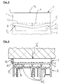
- Fig. 2 shows a sectional view of a preferred embodiment of the sealing element 1 according to the invention in the second state.
- three forces act on the sealing element 1.
- a first force F 1 which rests on the upper side 24 of the sealing element 1 and is preferably designed as a surface load, a second force F 2 and a third force F 3 , wherein the second and the third force F 2 , F 3 of the first force F 1 preferably counteract.
- the second force F 2 and the third force F 3 are spaced apart from each other and act on a significantly smaller area of the sealing element than the first force F 1 . It is understood that the sum of the second force F 2 and the third force F 3 has the same amount as the first force F 1 .
- the second force F 2 and the third force F 3 are preferably also surface forces or surface loads and preferably act on the second foam section 4 a.
- the sealing element 1 is placed in the second state, wherein the second state is characterized by a deformation of the sealing element 1.
- the first foam section 2 is compressed in such a way that it has a compressed first extension d 2 .
- the second foam section 4 is compressed in this context, this compression of the second foam section 4 is preferably significantly lower than the compression of the first foam section 2.
- the sealing element 1 in the second state a compressed total extension d 1 , wherein the ratio of the compressed first extension d 2 to the compressed total extent d 1 is preferably smaller than the ratio of the free first extent c 2 to the free total extent c 1 . Furthermore, formed by the concern of the three forces F 1 , F 2 and F 3, a curved portion b of the joining surface 22 from. Simultaneously with the joining surface 22 and the second foam portion and the lower part or the joining surface 22 and the surrounding areas of the first foam portion 2 is deformed accordingly, so that a curvature with a width b is formed, which in Fig. 2 is clearly shown.
- the neutral plane is preferably in the region of the joining surface 22, which is not curved as in the region of the width b.
- the neutral plane E is preferably in the region of the joining surface 22, at the height of which the second force F 2 and / or the third force F 3 act.
- the neutral plane E preferably be arranged at mid-height between the corresponding regions of the joining surface 22. It is particularly preferred that the first force F 1 is exerted by masonry on the sealing element 1.
- the second force F 2 and the third force F 3 result in this case preferably from the support of the sealing element 1 on a corresponding geometry of a window frame, wherein provided on the window frame projections in the manner such you in Fig. 2 or in Fig. 3 is shown act on the sealing element 1 and compress this.
- the curved portion of the joining surface 22 has a maximum distance a from the neutral plane. It is understood that in the region in which the joining surface 22 has the distance a from the neutral plane E, the first foam section 2 is less biased against the masonry acting from above on the first foam section 2 than in the regions at the right and left edges of the sealing element 1, in which the second force F 2 and the third force F 3 attack.
- This deformation of the first foam section 2 thus means that the sealing element in his, in Fig. 2 illustrated, middle region of the top 24 is pressed less strongly, for example, a masonry, whereby the sealing effect of the sealing element in this area is less than in the edge regions. It is therefore preferred that the distance a does not exceed the limit values proposed by the present invention, ie the sealing element 1 does not protrude beyond a specific value into a recess 62 or depression on a window frame 6.
- Fig. 3 shows a view of a preferred embodiment of the sealing element 1 according to the invention, in which on the underside of the sealing element 1, acting on the second foam section 4, a frame profile 6 is provided, which has a recess 62.
- the higher resistance of the material of the second foam section 4 to deformation ensures that the second foam section 4 supports the first foam section 2 and thus prevents the sealing element 1 from protruding too far into the recess 62 on the window frame 6.
- the distance a of the joining surface 22 from the neutral plane E exceeds the preferably provided limit values.
- the first foam section 2 also remains in its middle region with a sufficiently high contact pressure on the masonry arranged on the upper side of the sealing element 1.
- Fig. 4 shows a sectional view of a preferred embodiment of the sealing element 1 according to the invention in the installed state, or in the second state.
- the sealing element 1 between a masonry and a Frame profile 6 arranged.
- the frame profile 6 has a plurality of depressions 62.
- the total of five webs of the frame profile 6 each exert a force on the second foam section 4 of the sealing element 1, wherein the sum of the forces exerted by the frame profile 6 forces equal to the amount of surface load F 1 , which is transmitted from the masonry to the sealing element 1, is.
- the sealing profile 1 is deformed such that the joining surface 22 has curved portions with a width b.
Landscapes
- Engineering & Computer Science (AREA)
- Civil Engineering (AREA)
- Structural Engineering (AREA)
- Mechanical Engineering (AREA)
- Sealing Material Composition (AREA)
- Building Environments (AREA)
Abstract
Description
- Die vorliegende Erfindung betrifft ein Dichtungselement für den Einsatz am Bau.
- Dichtungselemente sind aus dem Stand der Technik bereits bekannt. So werden beispielsweise schaumstoffartig ausgebildete Dichtungselemente im Fensterbau eingesetzt, wobei diese zwischen einem Fensterrahmen und dem Mauerwerk im zusammengepressten Zustand eingefügt werden, um sich anschließend ausdehnen und einen zwischen dem Fensterrahmen und dem Mauerwerk bestehenden Spalt abzudichten. Die dabei verwendeten Materialien sind jedoch mitunter sehr kostenintensiv sowohl bezüglich der Materialpreise als auch in ihrer Herstellung. Weiterhin haben sich die bekannten Dichtungselemente als nachteilig erwiesen, wenn die Außengeometrie eines Fensterrahmens beispielsweise verschiedene Rücksprünge oder unebene Geometrien aufweist.
- Aufgabe der vorliegenden Erfindung ist es, Dichtungselemente dahingehend zu verbessern, dass sie kostengünstiger herzustellen und zu beschaffen sind und dass sie eine verbesserte Abdichtung des Spaltes zwischen Mauerwerk und Fensterrahmen auch bei ungleichmäßigen Außengeometrien der Fensterrahmen erlauben.
- Die vorliegende Aufgabe wird mit einem Dichtungselement gemäß Anspruch 1 gelöst. Weitere Vorteile und Merkmale der Erfindung ergeben sich aus den abhängigen Ansprüchen.
- Erfindungsgemäß ist ein Dichtungselement vorgesehen, welches einen ersten Schaumabschnitt und einen zweiten Schaumabschnitt aufweist, wobei der erste Schaumabschnitt und der zweite Schaumabschnitt aneinander gefügt sind, wobei der erste Schaumabschnitt eine Fügefläche zur Festlegung an dem zweiten Schaumabschnitt aufweist, welche sich in einem ersten Zustand des Dichtungselements im Wesentlichen in einer Neutralebenen erstreckt, wobei der zweite Schaumabschnitt eine höhere Widerstandsfähigkeit gegen Verformung aufweist als der erste Schaumabschnitt. Das Dichtungselement aus zwei Schaumabschnitten, von denen der zweite Schaumabschnitt eine höhere Widerstandsfähigkeit gegen Verformung, das heißt mit anderen Worten beispielsweise einen höheren E-Modul, als der erste Schaumabschnitt aufweist und auf diese Weise in de Lage ist, den ersten Schaumabschnitt und somit das gesamte Dichtungselement in einer Richtung zu stabilisieren. Dem Begriff Schaumabschnitt wohnt bereits die bevorzugte Ausbildung des Dichtungselements aus einem geschäumten Material inne. Dabei kann der zweite Schaumabschnitt mit Vorteil aus einem Schaummaterial mit vergleichsweise kleiner Porengröße gegenüber dem ersten Schaumabschnitt ausgebildet sein, um seine Festigkeit zu erhöhen. Vorzugsweise ist das Dichtungselement als Strang mit einem rechteckigen oder im Wesentlichen rechteckigen Querschnitt ausgebildet, wobei die Rechteckform insbesondere bevorzugt im ersten Zustand des Dichtungselements vorliegt. Der erste Zustand ist mit anderen Worten der Zustand, in dem keine äußeren Kräfte auf das Dichtungselement einwirken und dieses verformen. Der erste Schaumabschnitt weist eine Fügefläche auf, welche sich im ersten Zustand im Wesentlichen in einer Neutralebene erstreckt. Im Wesentlichen bedeutet in diesem Zusammenhang, dass kleinere Materialunebenheiten und Fertigungstoleranzen bei dieser Erstreckung der Fügefläche in der Ebene nicht berücksichtigt werden sollen. Für den Fall, dass die Fügefläche starke Amplituden relativ zu einer Ebene aufweist, mit anderen Worten also wellig ausgebildet ist, soll die Neutralebene als die mittlere Ebene definiert sein, in welcher sich die Fügefläche größtenteils erstreckt. Besonders bevorzugt ist das Dichtungselement derart ausgelegt, dass es in einen Spalt zwischen einem Fenster und dem Mauerwerk eines das Fenster umgebenden Gebäudes eingefügt werden kann. Dabei wird besonders bevorzugt der erste Schaumabschnitt mit seiner der Fügefläche gegenüberliegenden Seite in Richtung des Mauerwerks ausgerichtet und der zweite Schaumabschnitt mit seiner dem ersten Schaumabschnitt gegenüberliegenden Seite dem Fensterrahmen zugewandt ausgerichtet. Auf diese Weise kann der zweite Schaumabschnitt sich zumindest bereichsweise an dem Fensterrahmen abstützen und somit den ersten Schaumabschnitt vom Einsinken in Aussparungen am Fensterrahmen abhalten, beziehungsweise vor starker Verformung durch eventuell am Fensterrahmen vorhandene Rücksprünge oder Unebenheiten, schützen. Besonders bevorzugt ist dabei das Dichtungselement derart ausgelegt, dass es in einem vorgespannten Zustand zwischen dem Mauerwerk und dem Rahmen des Fensters anordenbar ist.
- Mit Vorteil ist das Dichtungselement unter Einwirken einer, vorzugsweise als Flächenlast ausgebildeten Kraft an der Oberseite des ersten Schaumabschnitts und zweier entgegenwirkender und voneinander beabstandeter Kräfte an dem zweiten Schaumabschnitt das Dichtungselement in einen zweiten Zustand versetzbar, wobei die Fügefläche im zweiten Zustand einen gekrümmten Abschnitt mit einer Breite aufweist und wobei im zweiten Zustand der erste Schaumabschnitt derart verformt ist, dass die Fügefläche einen Abstand zur Neutralebene aufweist, der kleiner ist als die Breite des gekrümmten Abschnitts der Fügefläche. Mit anderen Worten greift also an der Oberseite und an der Unterseite des Dichtungselements jeweils zumindest eine Kraft an, wobei die Kraft an der Oberseite des Dichtungselements auf den ersten Schaumabschnitt einwirkt und wobei die Kraft an der Unterseite des Dichtungselements auf den zweiten Schaumabschnitt übertragen wird. Durch diese beiden Kräfte wird das Dichtungselement derart verformt, dass die Fügefläche in zumindest einem Punkt einen Abstand zur Neutralebene aufweist. Die Neutralebene verläuft im zweiten Zustand des Dichtungselements dabei bevorzugt durch einen Bereich der Fügefläche, in welchem sich die Kraft an der Oberseite und die Kraft an der Unterseite genau gegenüberliegen, mit anderen Worten also in entgegengesetzter Richtung zueinander kollinear verlaufen. Insbesondere in dem Fall, dass die Kraft an der Oberseite durch ein Mauerwerk ausgeübt wird und somit eine auf das Dichtungselement einwirkende Flächenlast ist und die Kraft an der Unterseite beziehungsweise am zweiten Schaumabschnitt durch Auflagepunkte des Dichtungselements an einem Fensterrahmen entsteht, verläuft die Neutralebene also durch einen Bereich der Fügefläche, welcher vorzugsweise auf Höhe der Auflagepunkte des Fensterrahmens liegt. Das Dichtungselement stützt sich mit anderen Worten bevorzugt an einem Mauerwerk ab. Die Verschiebung der Fügefläche aus der Neutralebene heraus resultiert dabei aufgrund der elastischen Rückstellkraft des ersten Schaumabschnitts, welcher den zweiten Schaumabschnitt dort, wo dieser nicht durch den Fensterrahmen abgestützt ist, in Richtung vorzugsweise einer Vertiefung am Fensterrahmen schiebt. Mit anderen Worten definiert der zweite Zustand somit den eingebauten Zustand des Dichtungselements, wobei in diesem Zustand der zweite Schaumabschnitt seine abstützende Wirkung entfaltet. Es hat sich gezeigt, dass aus dem Stand der Technik bekannte Fensterprofile oft jeweils zwei nach außen ragende profilartige Stege aufweisen, an welchen das Dichtungselement zur Auflage gelangt. Es zeigt sich bei dieser und auch bei den weiteren folgenden Ausführungsformen insbesondere die vorteilhafte Eigenschaft des zweiten Schaumabschnitts, dass dieser auch dann, wenn die Geometrie des Fensterrahmens sehr scharfkantig sein sollte, wirksam verhindern kann, dass insbesondere in dem Eckenbereich des Einwirkens der Auflagekräfte des Fensterrahmens ein Anreißen des Dichtungselements verhindert werden kann. Hierfür weist das Material des zweiten Schaumabschnitts bevorzugt eine höhere Zugfestigkeit als das Material des ersten Schaumabschnitts auf und ist somit widerstandsfähiger gegenüber lokalen Spannungsspitzen, wie sie durch Kerbwirkung verursacht werden. Die Krümmung des gekrümmten Abschnitts der Fügefläche ist dabei insbesondere in einer Schnittansicht beziehungsweise entlang einer Schnittebene durch das Dichtungselement, welche senkrecht zur Neutralebene verläuft, bestimmbar.
- Vorzugsweise steht der maximale Abstand der Fügefläche von der Neutralebene zur Breite des gekrümmten Abschnitts in einem Verhältnis von 0,02 bis 0,2, vorzugsweise 0,04 bis 0,15 und besonders bevorzugt bei ca. 0,08 bis 0,12. Das hier beschriebene Verhältnis ist mit anderen Worten ein Ausdruck für die Leistungsfähigkeit des zweiten Schaumabschnitts, das Dichtungselement insgesamt bei Aufpressung auf einen Fensterrahmen gegen zu starke Verformung zu sichern. Dabei ist es verständlich, dass mit steigender Breite des gekrümmten Abschnitts, welche daraus resultiert, dass zwischen den beiden Auflagepunkten des Dichtungselements ein größerer Abstand besteht, auch die maximale Amplitude der Krümmung relativ zur Neutralebene ansteigt. Der maximale Abstand der Fügefläche von der Neutralebene ist somit mit anderen Worten der Punkt, an dem der zum zweiten Schaumabschnitt hingewandte Teil des ersten Schaumabschnitts am weitesten von der Neutralebene beabstandet ist oder mit anderen Worten am weitesten in eine an einem Fensterrahmen vorgesehene Aussparung hineinragt. Es ist dabei vor allem deswegen bevorzugt eine zu starke Verformung des Dichtungselements und insbesondere des ersten Schaumabschnitts zu verhindern, da, je weiter der erste Schaumabschnitt in die Aussparung eines Fensterrahmens hineinragt, desto geringer die Anpresskraft der Oberseite des ersten Schaumabschnitts gegenüber dem Mauerwerk wird. Es ist jedoch bevorzugt, dass das Dichtungselement auch gegenüber dem Mauerwerk mit einer möglichst konstanten, oder so gering wie möglich veränderten Anpresskraft anliegt. Auf diese Weise ist gewährleistet, dass insbesondere angesichts der in den meisten Fällen an einem Mauerwerk vorgesehenen Oberflächenunebenheiten trotzdem eine besonders gute Abdichtung durch das Dichtungselement zwischen Mauerwerk und Fensterrahmen erreicht werden kann. Indem das Dichtungselement nicht zu stark in eine Aussparung am Fensterrahmen hineinragt, verbleibt in dieser Aussparung ein größerer Anteil an Luft, welche ein guter Isolator gegen Wärmestrom ist. Somit leistet der zweite Schaumabschnitt einen effektiven Beitrag zur Erhöhung der Abdichtung des Spaltes zwischen Fensterrahmen und Mauerwerk und zur Senkung des Wärmeübertragungskoeffizienten dieses Bereiches des Bauwerks.
- Insbesondere bevorzugt weist das Dichtungselement im ersten Zustand eine freie Gesamtdicke auf, wobei der erste Schaumabschnitt im ersten Zustand eine freie erste Dicke aufweist und wobei das Verhältnis der freien ersten Dicke zur freien Gesamtdicke bei 0,6 bis 0,95, vorzugsweise bei 0,7 bis 0,9 und besonders bevorzugt bei ca. 0,85 bis 0,92 liegt. Das Verhältnis der freien Gesamtdicke, der Dicke des gesamten Dichtungselements quer zur Neutralebene also, und der freien ersten Dicke, der Dicke des ersten Schaumabschnitts quer zur Neutralebene also, ist mit anderen Worten ein Ausdruck dafür, dass bei einer bestimmten Gesamtdicke des Dichtungselements der erste Schaumabschnitt vorzugsweise nur einen bestimmten Anteil an dieser Gesamtdicke hält. Dies liegt zum einen darin begründet, dass durch eine Vergrößerung des Anteils der Dicke des zweiten Schaumabschnitts die Widerstandsfähigkeit des gesamten Dichtungselements gegenüber Verformung erhöht wird. Auf der anderen Seite ist es aber bevorzugt, den Anteil des ersten Schaumabschnitts an der freien Gesamtdicke nicht zu stark zu reduzieren, da der erste Schaumabschnitt vorzugsweise aus einem offenzelligen Schaummaterial ausgebildet ist, welches in besonders bevorzugter Ausführung getränkt ist und daher besonders vorteilhafte Eigenschaften für die Gesamtdichtungswirkung des Dichtungselements beisteuert. Die vorliegenden bevorzugten Verhältnisbereiche der freien ersten Dicke zur freien Gesamtdicke sind daher Ausdruck dieses Kompromisses aus einerseits Ausnutzung der vorteilhaften Dichtungseigenschaften des ersten Schaumabschnitts und andererseits der gesteigerten Stabilität durch eine bestimmte Mindestdicke des zweiten Schaumabschnitts.
- Weiterhin bevorzugt steht die komprimierte Gesamtdicke zur freien Gesamtdicke des Dichtungselements in einem Verhältnis von 0,25 bis 0,6, besonders bevorzugt von ca. 0,3 bis 0,33. Dieses bevorzugte Verhältnis ist ein Ausdruck für die Fähigkeit des Dichtungselements, einen Spalt zwischen einem Mauerwerk und einem Fensterrahmen gleichmäßig auszufüllen. Dabei wird beispielsweise ein Dichtungselement mit einer freien Gesamtdicke von 30mm im ersten Zustand auf eine komprimierte Gesamtdicke von 10mm im zweiten Zustand zusammengepresst und füllt auf diese Weise den Spalt besonders gut aus.
- Mit Vorteil weist der erste Schaumabschnitt im zweiten Zustand eine komprimierte erste Dicke auf, wobei der maximale Abstand der Fügefläche von der Neutralebene in einem Verhältnis von 0,03 bis 0,5, vorzugsweise von 0,03 bis 0,3 und besonders bevorzugt von ca. 0,06 bis 0,08 zur Differenz der freien ersten Dicke und der komprimierten ersten Dicke des ersten Schaumabschnitts steht. Das vorliegend beschriebene Verhältnis ist somit ein Ausdruck dafür, wie stark die erste Fügefläche und somit der erste Schaumabschnitt bei einer bestimmten Komprimierung des ersten Schaumabschnitts verformt wird. Eine Komprimierung des ersten Schaumabschnitts, welche zu einer reduzierten, nämlich der komprimierten ersten Dicke des ersten Schaumabschnitts führt, resultiert verständlicherweise aus einer Kompression des gesamten Dichtungselements. Der bevorzugte Verhältnisbereich von 0,03 bis 0,5 hat sich dabei als günstig erwiesen um bei einer bestimmten Kompression des Dichtungselements eine gute Dichtwirkung durch geringe Verformung der Fügefläche und gleichzeitig ausreichende Elastizität und niedrige Wärmeübergangskoeffizienten des ersten und des zweiten Schaumabschnitts zu ermöglichen. Mit Vorteil wird ein Verhältnis von 0,06 bis 0,08 bei einem Dichtungselement erreicht, welches eine Gesamtdicke von ca. 45mm aufweist und, wobei die Breite des gekrümmten Abschnitts bei ca. 30mm bis 40mm liegt. Es ist in diesem Zusammenhang aber ebenfalls bevorzugt, dass bei Zusammenpressen des Dichtungselements mit einer Kraft, welche im Wesentlichen senkrecht zur Neutralebene wirkt, der erste Schaumabschnitt eine deutlich größere Verformung erfährt, als der zweite Schaumabschnitt. Ursache hierfür ist die bevorzugt vorgesehen höhere Widerstandsfähigkeit des zweiten Schaumabschnitts gegenüber Verformung. Vorzugsweise wird die freie erste Dicke und die komprimierte erste Dicke jeweils am Randbereich des Dichtungselements gemessen oder alternativ in den Bereichen, in denen auch die Lage der Neutralebene durch die einander gegenüberstehenden, auf das Dichtungselement einwirkenden Kräfte liegen.
- In einer besonders bevorzugten Ausführungsform ist der erste Schaumabschnitt aus offenzelligem Polymerschaum hergestellt, wobei der zweite Schaumabschnitt vorzugsweise aus einem geschäumten Polyolefin hergestellt ist. Polyolefin als Herstellungsmaterial für den zweiten Schaumabschnitt eignet sich insbesondere daher, dass es günstiger herzustellen ist und eine höhere Festigkeit als offenzelliger Polymerschaum aufweist. Der zweite Schaumabschnitt ist dabei vorzugsweise aus einem geschlossenzelligen Material, vorzugsweise geschlossenzelligem Polyolefinschaum hergestellt. Die offenzellige Ausführung des Polymerschaums des ersten Schaumabschnitts erlaubt es, diesen zu imprägnieren und somit weitere vorteilhafte abdichtende Eigenschaften des ersten Schaumabschnitts zu generieren. Als bevorzugte Polyolefinmaterialien kommt für den zweiten Schaumabschnitt insbesondere bevorzugt Polypropylen zum Einsatz, da es eine hohe Festigkeit aufweist. Alternativ zu Polypropylen kann auch Polyethylen eingesetzt werden, da es besonders günstig und leicht herzustellen ist. Für ebenfalls gesteigerte Festigkeitswerte kann auch ein Zellkautschuk oder ein PUR-Schaum zum Einsatz gelangen.
- In einer weiterhin bevorzugten Ausführungsform ist der erste Schaumabschnitt mit dem zweiten Schaumabschnitt eines Klebers auf Acrylatbasis oder kautschukbasis verklebt. Ein Kleber auf Acrylatbasis zeichnet sich insbesondere durch eine hohe Lebensdauer und eine besonders feste stoffschlüssige Verbindung der beiden Schaumabschnitte aus. Weiterhin bevorzugt ist dieser Kleber geeignet, die bevorzugten Materialien des ersten und des zweiten Schaumabschnitts in gleicher Weise zu binden.
- Weiterhin bevorzugt ist die Druckspannung bei einer bestimmten Verformung des zweiten Schaumabschnitts ein 1,1- bis 3-faches, vorzugsweise ein 1,1- bis 2-faches und besonders bevorzugt ein 1- bis 1,5-faches der entsprechenden Druckspannung des ersten Schaumabschnitts. Die Ermittlung der Druckspannung ist ein übliches Verfahren, um die Widerstandsfähigkeit eines Schaum- oder eines Polymermaterials gegenüber von außen einwirkenden Druckkräften zu ermitteln. Dabei ist es bevorzugt, dass das Material des zweiten Schaumabschnitts insbesondere aufgrund einer höheren Dichte, der Verwendung festeren Materials und/oder durch eine geschlossenzellige Ausbildung des Schaumes einer bestimmten Verformung eine höhere Druckspannung entgegensetzt als dies beim Material des ersten Schaumabschnitts der Fall ist. Bei einer besonders bevorzugten Ausführungsform weist das Material des zweiten Schaumabschnitts eine Druckspannung von mehr als 15 kPa bei einer 10 %igen Verformung des Materials, eine Druckspannung von > 25 kPa bei einer 25 %igen Verformung und eine Druckspannung von > 80 kPa bei einer 50 %igen Verformung des Materials auf. Es ist verständlich, dass sich die Druckspannung, die das Material des zweiten Schaumabschnitts einer Verformung entgegensetzt, jeweils in einem Verhältnis zur Druckspannung, die das Material des ersten Schaumabschnitts einer bestimmten Verformung entgegensetzt, stehen muss. So ist bevorzugt, wenn das Material des ersten Schaumabschnitts eine relativ hohe Widerstandsfähigkeit gegen Verformung aufweist, auch das Material des zweiten Schaumabschnitts mit einer entsprechend gesteigerten, beziehungsweise im Vergleich zum Material des ersten Schaumabschnitts größeren, Widerstandsfähigkeit gegenüber Verformung auszulegen, damit der zweite Schaumabschnitt seine abstützende Wirkung gegenüber dem ersten Schaumabschnitt und somit dem gesamten Dichtungselement entfalten kann.
- In einer weiterhin bevorzugten Ausführungsform ist das Material des ersten Schaumabschnitts und/oder des zweiten Schaumabschnitts beständig gegen Temperaturen von bis zu 115° C. Temperaturbeständigkeit bedeutet in diesem Zusammenhang, dass das Material des Dichtungselements, vorzugsweise des ersten und/oder des zweiten Schaumabschnitts, bei hohen Temperaturen nur vernachlässigbare Materialänderungen erfährt. Eine hohe Temperaturbeständigkeit kann beispielsweise durch Einsatz entsprechender Imprägnierungen oder durch das Hinzufügen von Zusatzstoffen in die Herstellungsmaterialien des ersten sowie des zweiten Schaumabschnitts erreicht werden. Bei einer Temperaturbeständigkeit von bis zu 115° C und in bevorzugten Spezialanwendungsfällen sogar 120° C ist eine ausreichende Sicherheit gegen schädliche Veränderungen des Materials wie beispielsweise Schrumpfen oder Entstehung von Porositäten für die normalen Einsatzbereiche des Dichtungselements im Bauwesen gegeben. Insbesondere bevorzugt ist es, dass auch bei höheren Temperaturen, die am Dichtungselement anliegen, die abstützende Wirkung des zweiten Schaumabschnitts weiterhin nahezu unverändert gegeben ist. Hierdurch eignet sich das Dichtungselement auch zum Einsatz in südlicheren Gebieten, in welchen die Tagesdurchschnittstemperatur wesentlich höher ist als beispielsweise in Mitteleuropa.
- Weiterhin bevorzugt sind der erste und/oder der zweite Schaumabschnitt aus einem Material hergestellt, das schwer entflammbar nach DIN 75200 ist. Weiterhin bevorzugt sind der erste und/oder der zweite Schaumabschnitt normalentflammbar nach DIN 4102 - B2 und EN 13501-1 Klasse E. Die geringe Entflammbarkeit des Materials des ersten und/oder des zweiten Schaumabschnitts führt dazu, dass das Dichtungselement vorzugsweise auch in kritischen Teilen eines Hauses einsetzbar ist. Zur Steigerung der Widerstandsfähigkeit gegen Entflammung kann insbesondere bevorzugt eine Imprägnierung auf das Dichtungselement aufgebracht werden.
- Vorzugsweise verringert der zweite Schaumabschnitt ein Schrumpfen des Dichtungselements, wenn dieses auf Zug belastet wird. Die höhere Widerstandsfähigkeit gegen Verformung des Materials des zweiten Schaumabschnitts sorgt dafür, dass dieses und somit das gesamte Dichtungselements bei einer Zugbeanspruchung weniger stark gedehnt wird. Daher reduziert sich auch die Verringerung der Breite des Dichtungselements beim Einbau des Dichtungselements durch einen Monteur, welcher das Dichtungselement beispielsweise über die Ecken eines Fensterrahmens hinweg spannt. Es wird durch den Einsatz des zweiten Schaumabschnitts an einem Dichtungselement auf diese Weise bevorzugt die Formstabilität des Dichtungselements beim Einbau erhöht, wobei die Anpassung eines bestimmten Dichtungselements für einen bestimmten Fensterrahmen auch während des Einbaus erhalten bleibt.
- Weitere Vorteile und Merkmale der vorliegenden Erfindung ergeben sich aus der nachfolgenden Beschreibung mit Bezug auf die beigefügten Figuren. Es versteht sich dabei, dass einzelne der einzelnen Ausführungsformen im Rahmen der vorliegenden Erfindung miteinander kombiniert werden können.
- Es zeigen:
- Fig. 1
- eine Schnittansicht einer bevorzugten Ausführungsform des erfindungsgemäßen Dichtungselements im ersten Zustand,
- Fig. 2
- eine bevorzugte Ausführungsform des erfindungsgemäßen Dichtungselements im zweiten Zustand,
- Fig. 3
- eine weitere Ansicht einer bevorzugten Ausführungsform des erfindungsgemäßen Dichtungselements im zweiten Zustand, und
- Fig. 4
- eine Schnittansicht der Einbausituation einer bevorzugten Ausführungsform des erfindungsgemäßen Dichtungselements.
- Das in
Fig. 1 dargestellte Dichtungselement 1 weist einen ersten Schaumabschnitt 2 und einen zweiten Schaumabschnitt 4 auf, wobei die beiden Schaumabschnitte 2 und 4 vorzugsweise an einer ersten Fügefläche 22 des ersten Schaumabschnitts 2 zusammengefügt sind. Zur Verbindung des ersten Schaumabschnitts 2 und des zweiten Schaumabschnitts 4 ist vorzugsweise ein Acrylatkleber vorgesehen. Weiterhin geht ausFig. 1 deutlich hervor, dass das Dichtungselement 1 eine vorzugsweise rechteckige Form aufweist. Der inFig. 1 gezeigte erste Zustand des Dichtungselements 1 ist dabei dadurch gekennzeichnet, dass keine äußeren Kräfte auf das Dichtungselement 1 einwirken und dieses somit spannungsfrei und ohne Verformung vorliegt. Im ersten Zustand erstreckt sich die Fügefläche 22 vorzugsweise entlang einer Neutralebene E. Für den Fall, dass die Fügefläche 22 eine wellige oder ähnlich ausgebildete Struktur hat, ist vorgesehen, dass die Neutralebene E die mittlere Erstreckungsrichtung beziehungsweise Erstreckungsfläche der Fügefläche 22 ist. Für die inFig. 1 dargestellte Schnittansicht würde dies bedeuten, dass, wenn die Schnittansicht der Fügefläche 22 beispielsweise einen sinusförmigen Verlauf hätte, die Schnittansicht (Gerade) der Neutralebene E entsprechend mittig zwischen den positiven sowie negativen Amplitudenwerten der Schnittkurve der Fügefläche 22 liege würde. Im ersten Zustand weist das Dichtungselement 1 eine freie Gesamterstreckung c1 auf, welche sich quer zur Neutralebene E erstreckt. Weiterhin weist der erste Schaumabschnitt im ersten Zustand des Dichtungselements 1 eine freie erste Erstreckung c2 auf. Vorzugsweise ist dabei das Verhältnis der freien ersten Erstreckung c2 zur freien Gesamterstreckung c1 ungefähr 0,6 bis 0,95. -
Fig. 2 zeigt eine Schnittansicht einer bevorzugten Ausführungsform des erfindungsgemäßen Dichtungselements 1 im zweiten Zustand. Es wirken dabei in dieser Ausführungsform drei Kräfte auf das Dichtungselement 1 ein. Eine erste Kraft F1, welche auf der Oberseite 24 des Dichtungselements 1 anliegt und vorzugsweise als Flächenlast ausgelegt ist, eine zweite Kraft F2 und eine dritte Kraft F3, wobei die zweite und die dritte Kraft F2, F3 der ersten Kraft F1 vorzugsweise entgegenwirken. Weiterhin sind die zweite Kraft F2 und die dritte Kraft F3 voneinander beabstandet und wirken auf eine deutlich kleinere Fläche des Dichtungselements ein als die erste Kraft F1. Es versteht sich, dass die Summe der zweiten Kraft F2 und der dritten Kraft F3 den gleichen Betrag aufweist wie die erste Kraft F1. Die zweite Kraft F2 und die dritte Kraft F3 sind dabei vorzugsweise ebenfalls Flächenkräfte beziehungsweise Flächenlasten und wirken vorzugsweise auf den zweiten Schaumabschnitt 4 ein. Durch das Anliegen der drei Kräfte, F1, F2 und F3 wird das Dichtungselement 1 in den zweiten Zustand versetzt, wobei der zweite Zustand durch eine Verformung des Dichtungselements 1 gekennzeichnet ist. Dabei wird zum einen der erste Schaumabschnitt 2 derart komprimiert, dass er eine komprimierte erste Erstreckung d2 aufweist. Auch der zweite Schaumabschnitt 4 wird in diesem Zusammenhang komprimiert, wobei diese Kompression des zweiten Schaumabschnitts 4 bevorzugt deutlich geringer ist als die Kompression des ersten Schaumabschnitts 2. Insgesamt weist das Dichtungselement 1 im zweiten Zustand eine komprimierte Gesamterstreckung d1 auf, wobei das Verhältnis der komprimierten ersten Erstreckung d2 zur komprimierten Gesamterstreckung d1 vorzugsweise kleiner ist als das Verhältnis der freien ersten Erstreckung c2 zur freien Gesamterstreckung c1. Weiterhin bildet sich durch das Anliegen der drei Kräfte F1, F2 und F3 ein gekrümmter Abschnitt b der Fügefläche 22 aus. Gleichzeitig mit der Fügefläche 22 wird auch der zweite Schaumabschnitt sowie der untere Teil beziehungsweise die Fügefläche 22 und die umliegenden Bereiche des ersten Schaumabschnitts 2 entsprechend verformt, so dass sich eine Krümmung mit einer Breite b ausbildet, welche inFig. 2 deutlich dargestellt ist. Im zweiten Zustand liegt die Neutralebene vorzugsweise in dem Bereich der Fügefläche 22, welcher nicht, wie im Bereich der Breite b gekrümmt ausgebildet ist. Mit anderen Worten liegt die Neutralebene E vorzugsweise in dem Bereich der Fügefläche 22, auf dessen Höhe die zweite Kraft F2 und/oder die dritte Kraft F3 einwirken. Für den Fall, dass die zweite Kraft F2 und die dritte Kraft F3 verschieden groß sind und somit die Fügefläche 22 eine verschiedene Höhe relativ zur Neutralebene E in den Bereichen des Eingriffs der beiden Kräfte F2 und F3 aufweist, wird die Neutralebene E vorzugsweise auf mittlerer Höhe zwischen den entsprechenden Bereichen der Fügefläche 22 angeordnet sein. Insbesondere bevorzugt ist es, dass die erste Kraft F1 durch ein Mauerwerk auf das Dichtungselement 1 ausgeübt wird. Die zweite Kraft F2 und die dritte Kraft F3 resultieren dabei vorzugsweise aus der Auflage des Dichtungselements 1 auf einer entsprechenden Geometrie eines Fensterrahmens, wobei am Fensterrahmen vorgesehene Vorsprünge in der Weise, wie sie inFig. 2 beziehungsweise inFig. 3 dargestellt ist, auf das Dichtungselement 1 einwirken und dieses komprimieren. Vorzugsweise weist der gekrümmte Abschnitt der Fügefläche 22 einen maximalen Abstand a von der Neutralebene auf. Es versteht sich, dass in dem Bereich, in dem die Fügefläche 22 den Abstand a zur Neutralebene E aufweist, der erste Schaumabschnitt 2 weniger stark vorgespannt gegenüber dem von oben auf den ersten Schaumabschnitt 2 einwirkenden Mauerwerk ist als in den Bereichen am rechten und linken Rand des Dichtungselements 1, in denen die zweite Kraft F2 und die dritte Kraft F3 angreifen. Diese Verformung des ersten Schaumabschnitts 2 bedeutet somit, dass das Dichtungselement in seinem, inFig. 2 dargestellten, mittleren Bereich der Oberseite 24 weniger stark an beispielsweise ein Mauerwerk gepresst ist, wobei dadurch die Dichtwirkung des Dichtungselements in diesem Bereich geringer ist als in den Randbereichen. Es ist daher bevorzugt, dass der Abstand a die von der vorliegenden Erfindung vorgeschlagenen Grenzwerte nicht überschreitet, das Dichtungselement 1 also nicht über einen bestimmten Wert hinaus in eine Aussparung 62 beziehungsweise Vertiefung an einem Fensterrahmen 6 hineinragt. -
Fig. 3 zeigt eine Ansicht einer bevorzugten Ausführungsform des erfindungsgemäßen Dichtungselements 1, bei der auf der Unterseite des Dichtungselements 1, an den zweiten Schaumabschnitt 4 angreifend, ein Rahmenprofil 6 vorgesehen ist, welches eine Vertiefung 62 aufweist. Die höhere Widerstandsfähigkeit des Materials des zweiten Schaumabschnitts 4 gegenüber Verformung sorgt dabei dafür, dass der zweite Schaumabschnitt 4 den ersten Schaumabschnitt 2 abstützt und somit verhindert, dass das Dichtungselement 1 zu weit in die Aussparung 62 am Fensterrahmen 6 hineinragt. Gleichzeitig wird dabei verhindert, dass der Abstand a der Fügefläche 22 von der Neutralebene E die bevorzugt vorgesehenen Grenzwerte überschreitet. Dabei bleibt der erste Schaumabschnitt 2 auch in seinem mittleren Bereich mit einer ausreichend hohen Anpresskraft an dem an der Oberseite des Dichtungselements 1 angeordneten Mauerwerk gehalten. -
Fig. 4 zeigt eine Schnittansicht einer bevorzugten Ausführungsform des erfindungsgemäßen Dichtungselements 1 im eingebauten Zustand, bzw. im zweiten Zustand. Dabei ist das Dichtungselement 1 zwischen einem Mauerwerk und einem Rahmenprofil 6 angeordnet. Das Rahmenprofil 6 weist dabei eine Vielzahl von Vertiefungen 62 auf. Die insgesamt fünf Stege des Rahmenprofils 6 üben je ein Kraft auf den zweiten Schaumabschnitt 4 des Dichtungselements 1 aus, wobei die Summe der vom Rahmenprofil 6 ausgeübten Kräfte gleich dem Betrag der Flächenlast F1, welche vom Mauerwerk auf das Dichtungselement 1 übertragen wird, ist. Zwischen den Stegen des Rahmenprofils 6 ist das Dichtungsprofil 1 derart verformt, dass die Fügefläche 22 gekrümmte Abschnitte mit einer Breite b aufweist. -
- 1 -
- Dichtungselement
- 2 -
- erster Schaumabschnitt
- 22 -
- Fügefläche
- 24 -
- Oberseite
- 4 -
- zweiter Schaumabschnitt
- 6 -
- Rahmenprofil
- 62 -
- Vertiefung
- E -
- Neutralebene
- a -
- Abstand Fügefläche zur Neutralebene
- b -
- Breite des gekrümmten Abschnitts
- c1 -
- freie erste Dicke
- c2 -
- freie Gesamtdicke
- d1 -
- komprimierte erste Dicke
- d2 -
- komprimierte Gesamtdicke
- F1, F2, F3 -
- Kraft
Claims (13)
- Dichtungselement (1), umfassend einen ersten Schaumabschnitt (2) und einen zweiten Schaumabschnitt (4),
wobei der erste Schaumabschnitt (2) und der zweite Schaumabschnitt (4) aneinander gefügt sind,
wobei der erste Schaumabschnitt (2) eine Fügefläche (22) zur Festlegung an dem zweiten Schaumabschnitt (4) aufweist, welche sich in einem ersten Zustand des Dichtungselements (1) im Wesentlichen in einer Neutralebene (E) erstreckt,
wobei das Material des zweiten Schaumabschnitts (4) eine höhere Widerstandsfähigkeit gegen Verformung aufweist als das Material des ersten Schaumabschnitts (2). - Dichtungselement nach Ansprüche 1,
wobei unter Einwirken einer Kraft (F1) an einer Oberseite (24) des ersten Schaumabschnitts (2) und zweier entgegenwirkender und voneinander beabstandeter Kräfte (F2, F3) auf den zweiten Schaumabschnitt (4) das Dichtungselement (1) in einen zweiten Zustand versetzbar ist,
wobei im zweiten Zustand die Fügefläche (22) einen gekrümmten Abschnitt mit einer Breite (b) aufweist,
wobei im zweiten Zustand der erste Schaumabschnitt (2) derart verformt ist, dass die Fügefläche (22) einen Abstand (a) zur Neutralebene (E) aufweist der kleiner ist als die Breite (b) des gekrümmten Abschnitts. - Dichtungselement (1) nach Anspruch 2,
wobei der maximale Abstand (a) der Fügefläche (22) von der Neutralebene (E) zur Breite des ersten gekrümmten Abschnitts (b) in einem Verhältnis von 0,02 bis 0,2, vorzugsweise 0,04 bis 0,15 und besonders bevorzugt bei ca. 0,08 bis 0,12 steht. - Dichtungselement (1) nach einem der vorhergehenden Ansprüche,
wobei das Dichtungselement (1) im ersten Zustand eine freie Gesamtdicke (c1) aufweist und wobei der erste Schaumabschnitt (2) im ersten Zustand eine freie erste Dicke (c2), wobei das Verhältnis der freien ersten Dicke (c2) zur freien Gesamtdicke (c1) bei 0,6 bis 0,95, vorzugsweise bei 0,7 bis 0,9 und besonders bevorzugt bei ca. 0,85 bis 0,92 liegt. - Dichtungselement (1) nach Anspruch 4, wobei die komprimierte Gesamtdicke (d1) zur freien Gesamtdicke (c1) des Dichtungselements (1) in einem Verhältnis von 0,25 bis 0,6, besonders bevorzugt von ca. 0,3 bis 0,33, steht.
- Dichtungselement (1) nach einem der Ansprüche 2 bis 5,
wobei der erste Schaumabschnitt (2) im zweiten Zustand eine komprimierte erste Dicke (d2) aufweist, wobei der maximale Abstand (a) der Fügefläche (22) von der Neutralebene (E) in einem Verhältnis von 0,03 bis 0,5, vorzugsweise von 0,03 bis 0,3 und besonders bevorzugt von ca. 0,06 bis 0,08 zur Differenz der freien ersten Dicke (c2) und der komprimierten ersten Dicke (d2) des ersten Schaumabschnittes (2) steht. - Dichtungselement (1) nach einem der vorhergehenden Ansprüche, wobei der erste Schaumabschnitt (2) aus offenzelligem Polymerschaum hergestellt ist, und wobei der zweite Schaumabschnitt (4) aus einem geschäumten Polyolefin hergestellt ist.
- Dichtungselement (1) nach einem der vorhergehenden Ansprüche,
wobei der erste Schaumabschnitt (2) und der zweite Schaumabschnitt (4) mit einem Kleber auf Acrylat- oder Kautschukbasis miteinander verklebt sind. - Dichtungselement (1) nach einem der vorhergehenden Ansprüche,
wobei die Druckspannung bei einer bestimmten Verformung des zweiten Schaumabschnitts (4) ein 1,1- bis 3-faches, vorzugsweise ein 1,1- bis 2-faches und besonders bevorzugt ein 1- bis 1,5-faches der entsprechenden Druckspannung des ersten Schaumabschnitts (2) ist. - Dichtungselement (1) nach einem der vorhergehenden Ansprüche,
wobei das Material des ersten Schaumabschnitts (2) und/oder des zweiten Schaumabschnitts (4) beständig gegen Temperaturen von bis zu 115°C ist, insbesondere indem das Material des ersten Schaumabschnitts (2) und/oder zweiten Schaumabschnitts (4) imprägniert oder mit Zusatzstoffen versehen ist. - Dichtungselement (1) nach einem der vorhergehenden Ansprüche,
wobei der erste Schaumabschnitt (2) und/oder der zweite Schaumabschnitt (4) aus einem Material hergestellt sind, das schwer entflammbar nach DIN 75200 ist, insbesondere indem das Material des ersten Schaumabschnitts (2) und/oder zweiten Schaumabschnitts (4) imprägniert ist. - Dichtungselement (1) nach einem der vorhergehenden Ansprüche, wobei der zweite Schaumabschnitt (4) derart ausgebildet ist, ein Schrumpfen des Dichtungselements (1) zu verringern, wenn dieses auf Zug belastet wird.
- Dichtungselement (1) nach einem der vorhergehenden Ansprüche, wobei der erste Schaumabschnitt (2) und der zweite Schaumabschnitt (4) aus geschäumten Material ausgebildet sind.
Applications Claiming Priority (1)
| Application Number | Priority Date | Filing Date | Title |
|---|---|---|---|
| DE102014104098.8A DE102014104098B4 (de) | 2014-03-25 | 2014-03-25 | Dichtungselement |
Publications (1)
| Publication Number | Publication Date |
|---|---|
| EP2924220A1 true EP2924220A1 (de) | 2015-09-30 |
Family
ID=53385434
Family Applications (1)
| Application Number | Title | Priority Date | Filing Date |
|---|---|---|---|
| EP15159357.1A Ceased EP2924220A1 (de) | 2014-03-25 | 2015-03-17 | Dichtungselement |
Country Status (2)
| Country | Link |
|---|---|
| EP (1) | EP2924220A1 (de) |
| DE (1) | DE102014104098B4 (de) |
Cited By (1)
| Publication number | Priority date | Publication date | Assignee | Title |
|---|---|---|---|---|
| CN112654147A (zh) * | 2019-10-11 | 2021-04-13 | 大陆汽车有限公司 | 电路组件 |
Families Citing this family (1)
| Publication number | Priority date | Publication date | Assignee | Title |
|---|---|---|---|---|
| DE102020129429A1 (de) | 2020-11-09 | 2022-05-12 | Dr. Ing. H.C. F. Porsche Aktiengesellschaft | Dichtungsanordnung zur Abdichtung von Teilen sowie Gehäuseanordnung |
Citations (4)
| Publication number | Priority date | Publication date | Assignee | Title |
|---|---|---|---|---|
| DE4123647A1 (de) * | 1991-06-01 | 1992-12-03 | Irbit Research & Consulting Ag | Dichtband |
| DE202009010969U1 (de) * | 2009-07-16 | 2010-12-02 | Odenwald-Chemie Gmbh | Schalldämpfelement |
| EP2336442A1 (de) * | 2009-12-11 | 2011-06-22 | ISO-Chemie GmbH | Dichtband und Verfahren zur Ausrüstung eines Bauteils mit diesem Dichtband |
| EP2428632A1 (de) * | 2010-09-08 | 2012-03-14 | ISO-Chemie GmbH | Dichtband aus weichem Schaumstoff |
Family Cites Families (5)
| Publication number | Priority date | Publication date | Assignee | Title |
|---|---|---|---|---|
| DD236137A1 (de) * | 1985-04-09 | 1986-05-28 | Leuna Werke Veb | Einbaudichtung fuer fenster und tueren |
| DE8715499U1 (de) * | 1987-11-23 | 1989-03-23 | Irbit Research + Consulting Ag, Freiburg/Fribourg | Dichtungselement |
| US5000992A (en) * | 1989-06-01 | 1991-03-19 | The Dow Chemical Company | Coextruded multilayer foamed film for plastic container closures and process for manufacture |
| DE4436280A1 (de) * | 1994-10-11 | 1996-04-18 | Chemie Linz Deutschland | Dauerelastisches Dichtungselement zur im Brandfall wirksamen Abdichtung von Öffnungen in Bauteilen, insbesondere von Fugen |
| DE102005027733B3 (de) * | 2005-06-16 | 2007-01-04 | Polymer-Tec Halbzeuge Gmbh | Dichtungseinlage für eine Verschlusskappe eines Flüssigkeitsbehälters |
-
2014
- 2014-03-25 DE DE102014104098.8A patent/DE102014104098B4/de active Active
-
2015
- 2015-03-17 EP EP15159357.1A patent/EP2924220A1/de not_active Ceased
Patent Citations (4)
| Publication number | Priority date | Publication date | Assignee | Title |
|---|---|---|---|---|
| DE4123647A1 (de) * | 1991-06-01 | 1992-12-03 | Irbit Research & Consulting Ag | Dichtband |
| DE202009010969U1 (de) * | 2009-07-16 | 2010-12-02 | Odenwald-Chemie Gmbh | Schalldämpfelement |
| EP2336442A1 (de) * | 2009-12-11 | 2011-06-22 | ISO-Chemie GmbH | Dichtband und Verfahren zur Ausrüstung eines Bauteils mit diesem Dichtband |
| EP2428632A1 (de) * | 2010-09-08 | 2012-03-14 | ISO-Chemie GmbH | Dichtband aus weichem Schaumstoff |
Cited By (1)
| Publication number | Priority date | Publication date | Assignee | Title |
|---|---|---|---|---|
| CN112654147A (zh) * | 2019-10-11 | 2021-04-13 | 大陆汽车有限公司 | 电路组件 |
Also Published As
| Publication number | Publication date |
|---|---|
| DE102014104098A1 (de) | 2015-10-01 |
| DE102014104098B4 (de) | 2019-01-24 |
Similar Documents
| Publication | Publication Date | Title |
|---|---|---|
| EP1811111B2 (de) | Fensterlaibung mit einem Fensterrahmen und einem Dichtstreifen | |
| EP2801662B1 (de) | Holzpflasterstein und zugehöriger Holzflächenbelag | |
| EP2666949B1 (de) | Fenster- oder Türflügel | |
| EP2584133A1 (de) | Verfahren zur Abdichtung bei der Fenstersanierung | |
| DE102014111149A1 (de) | Dichtungselement und Verfahren zu seiner Herstellung | |
| EP2824249B1 (de) | Thermisch isolierendes Bauelement | |
| DE102014104098B4 (de) | Dichtungselement | |
| DE19543768A1 (de) | Balkonanschluß | |
| EP0250612A1 (de) | Gerüstboden für ein Schnellbaugerüst | |
| EP2893097B1 (de) | Bauelement zur fassadendämmung und verfahren zu seiner herstellung | |
| DE102014106068A1 (de) | Vorrichtung zur Verbindung zweier einander gegenüberliegender plattenförmiger Schalungselemente | |
| DE202013103694U1 (de) | Verbundplatte mit Dichtband | |
| WO2012126025A1 (de) | Vorrichtung zur überbrückung einer dehnungsfuge | |
| EP2859169B1 (de) | Dichtungsprofil | |
| EP2836662B1 (de) | Dichtsystem zwischen einem fensterrahmen und einer wand eines gebäudes | |
| EP3141673A1 (de) | Gekantetes blech | |
| EP1956174A1 (de) | Profilschiene zum Positionieren eines Befestigungselements und Verfahren zum Herstellen einer Mehrfachverglasungseinheit | |
| DE102016105124A1 (de) | Schiebeflügel für eine Schiebetüranordnung | |
| EP3045601B1 (de) | Pfosten-riegel-konstruktion | |
| EP4249782B1 (de) | Schalldämmeinlage aus einem dämmmaterial für eine rohrschelle und rohrschelle, die eine derartige schalldämmeinlage umfasst | |
| DE102017010647A1 (de) | Mauerwerk mit verbessertem Schallschutz sowie System zu dessen Herstellung | |
| DE202016106996U1 (de) | Glasklotzbrücke sowie diese umfassender Fenster- oder Türflügel | |
| EP3141412B1 (de) | Dichtungsstrang | |
| DE3134395A1 (de) | Bodenelement zur waermeisolierung eines fussbodens | |
| DE8003912U1 (de) | Waermedaemmplattensatz |
Legal Events
| Date | Code | Title | Description |
|---|---|---|---|
| PUAI | Public reference made under article 153(3) epc to a published international application that has entered the european phase |
Free format text: ORIGINAL CODE: 0009012 |
|
| AK | Designated contracting states |
Kind code of ref document: A1 Designated state(s): AL AT BE BG CH CY CZ DE DK EE ES FI FR GB GR HR HU IE IS IT LI LT LU LV MC MK MT NL NO PL PT RO RS SE SI SK SM TR |
|
| AX | Request for extension of the european patent |
Extension state: BA ME |
|
| 17P | Request for examination filed |
Effective date: 20151120 |
|
| RBV | Designated contracting states (corrected) |
Designated state(s): AL AT BE BG CH CY CZ DE DK EE ES FI FR GB GR HR HU IE IS IT LI LT LU LV MC MK MT NL NO PL PT RO RS SE SI SK SM TR |
|
| STAA | Information on the status of an ep patent application or granted ep patent |
Free format text: STATUS: EXAMINATION IS IN PROGRESS |
|
| 17Q | First examination report despatched |
Effective date: 20161212 |
|
| STAA | Information on the status of an ep patent application or granted ep patent |
Free format text: STATUS: THE APPLICATION HAS BEEN REFUSED |
|
| 18R | Application refused |
Effective date: 20180619 |