EP2924295A1 - Rotationsverdichter - Google Patents
Rotationsverdichter Download PDFInfo
- Publication number
- EP2924295A1 EP2924295A1 EP15161483.1A EP15161483A EP2924295A1 EP 2924295 A1 EP2924295 A1 EP 2924295A1 EP 15161483 A EP15161483 A EP 15161483A EP 2924295 A1 EP2924295 A1 EP 2924295A1
- Authority
- EP
- European Patent Office
- Prior art keywords
- refrigerant
- pipe
- accumulator
- opening
- sealing member
- Prior art date
- Legal status (The legal status is an assumption and is not a legal conclusion. Google has not performed a legal analysis and makes no representation as to the accuracy of the status listed.)
- Granted
Links
Images


Classifications
-
- F—MECHANICAL ENGINEERING; LIGHTING; HEATING; WEAPONS; BLASTING
- F04—POSITIVE - DISPLACEMENT MACHINES FOR LIQUIDS; PUMPS FOR LIQUIDS OR ELASTIC FLUIDS
- F04C—ROTARY-PISTON, OR OSCILLATING-PISTON, POSITIVE-DISPLACEMENT MACHINES FOR LIQUIDS; ROTARY-PISTON, OR OSCILLATING-PISTON, POSITIVE-DISPLACEMENT PUMPS
- F04C23/00—Combinations of two or more pumps, each being of rotary-piston or oscillating-piston type, specially adapted for elastic fluids; Pumping installations specially adapted for elastic fluids; Multi-stage pumps specially adapted for elastic fluids
- F04C23/008—Hermetic pumps
-
- F—MECHANICAL ENGINEERING; LIGHTING; HEATING; WEAPONS; BLASTING
- F04—POSITIVE - DISPLACEMENT MACHINES FOR LIQUIDS; PUMPS FOR LIQUIDS OR ELASTIC FLUIDS
- F04C—ROTARY-PISTON, OR OSCILLATING-PISTON, POSITIVE-DISPLACEMENT MACHINES FOR LIQUIDS; ROTARY-PISTON, OR OSCILLATING-PISTON, POSITIVE-DISPLACEMENT PUMPS
- F04C18/00—Rotary-piston pumps specially adapted for elastic fluids
- F04C18/30—Rotary-piston pumps specially adapted for elastic fluids having the characteristics covered by two or more of groups F04C18/02, F04C18/08, F04C18/22, F04C18/24, F04C18/48, or having the characteristics covered by one of these groups together with some other type of movement between co-operating members
- F04C18/34—Rotary-piston pumps specially adapted for elastic fluids having the characteristics covered by two or more of groups F04C18/02, F04C18/08, F04C18/22, F04C18/24, F04C18/48, or having the characteristics covered by one of these groups together with some other type of movement between co-operating members having the movement defined in group F04C18/08 or F04C18/22 and relative reciprocation between the co-operating members
-
- F—MECHANICAL ENGINEERING; LIGHTING; HEATING; WEAPONS; BLASTING
- F04—POSITIVE - DISPLACEMENT MACHINES FOR LIQUIDS; PUMPS FOR LIQUIDS OR ELASTIC FLUIDS
- F04C—ROTARY-PISTON, OR OSCILLATING-PISTON, POSITIVE-DISPLACEMENT MACHINES FOR LIQUIDS; ROTARY-PISTON, OR OSCILLATING-PISTON, POSITIVE-DISPLACEMENT PUMPS
- F04C29/00—Component parts, details or accessories of pumps or pumping installations, not provided for in groups F04C18/00 - F04C28/00
- F04C29/0042—Driving elements, brakes, couplings, transmissions specially adapted for pumps
- F04C29/0085—Prime movers
-
- F—MECHANICAL ENGINEERING; LIGHTING; HEATING; WEAPONS; BLASTING
- F04—POSITIVE - DISPLACEMENT MACHINES FOR LIQUIDS; PUMPS FOR LIQUIDS OR ELASTIC FLUIDS
- F04C—ROTARY-PISTON, OR OSCILLATING-PISTON, POSITIVE-DISPLACEMENT MACHINES FOR LIQUIDS; ROTARY-PISTON, OR OSCILLATING-PISTON, POSITIVE-DISPLACEMENT PUMPS
- F04C29/00—Component parts, details or accessories of pumps or pumping installations, not provided for in groups F04C18/00 - F04C28/00
- F04C29/04—Heating; Cooling; Heat insulation
- F04C29/042—Heating; Cooling; Heat insulation by injecting a fluid
-
- F—MECHANICAL ENGINEERING; LIGHTING; HEATING; WEAPONS; BLASTING
- F04—POSITIVE - DISPLACEMENT MACHINES FOR LIQUIDS; PUMPS FOR LIQUIDS OR ELASTIC FLUIDS
- F04C—ROTARY-PISTON, OR OSCILLATING-PISTON, POSITIVE-DISPLACEMENT MACHINES FOR LIQUIDS; ROTARY-PISTON, OR OSCILLATING-PISTON, POSITIVE-DISPLACEMENT PUMPS
- F04C29/00—Component parts, details or accessories of pumps or pumping installations, not provided for in groups F04C18/00 - F04C28/00
- F04C29/12—Arrangements for admission or discharge of the working fluid, e.g. constructional features of the inlet or outlet
-
- F—MECHANICAL ENGINEERING; LIGHTING; HEATING; WEAPONS; BLASTING
- F25—REFRIGERATION OR COOLING; COMBINED HEATING AND REFRIGERATION SYSTEMS; HEAT PUMP SYSTEMS; MANUFACTURE OR STORAGE OF ICE; LIQUEFACTION SOLIDIFICATION OF GASES
- F25B—REFRIGERATION MACHINES, PLANTS OR SYSTEMS; COMBINED HEATING AND REFRIGERATION SYSTEMS; HEAT PUMP SYSTEMS
- F25B39/00—Evaporators; Condensers
- F25B39/02—Evaporators
-
- F—MECHANICAL ENGINEERING; LIGHTING; HEATING; WEAPONS; BLASTING
- F25—REFRIGERATION OR COOLING; COMBINED HEATING AND REFRIGERATION SYSTEMS; HEAT PUMP SYSTEMS; MANUFACTURE OR STORAGE OF ICE; LIQUEFACTION SOLIDIFICATION OF GASES
- F25B—REFRIGERATION MACHINES, PLANTS OR SYSTEMS; COMBINED HEATING AND REFRIGERATION SYSTEMS; HEAT PUMP SYSTEMS
- F25B39/00—Evaporators; Condensers
- F25B39/04—Condensers
-
- F—MECHANICAL ENGINEERING; LIGHTING; HEATING; WEAPONS; BLASTING
- F25—REFRIGERATION OR COOLING; COMBINED HEATING AND REFRIGERATION SYSTEMS; HEAT PUMP SYSTEMS; MANUFACTURE OR STORAGE OF ICE; LIQUEFACTION SOLIDIFICATION OF GASES
- F25B—REFRIGERATION MACHINES, PLANTS OR SYSTEMS; COMBINED HEATING AND REFRIGERATION SYSTEMS; HEAT PUMP SYSTEMS
- F25B43/00—Arrangements for separating or purifying gases or liquids; Arrangements for vaporising the residuum of liquid refrigerant, e.g. by heat
- F25B43/006—Accumulators
-
- F—MECHANICAL ENGINEERING; LIGHTING; HEATING; WEAPONS; BLASTING
- F25—REFRIGERATION OR COOLING; COMBINED HEATING AND REFRIGERATION SYSTEMS; HEAT PUMP SYSTEMS; MANUFACTURE OR STORAGE OF ICE; LIQUEFACTION SOLIDIFICATION OF GASES
- F25B—REFRIGERATION MACHINES, PLANTS OR SYSTEMS; COMBINED HEATING AND REFRIGERATION SYSTEMS; HEAT PUMP SYSTEMS
- F25B43/00—Arrangements for separating or purifying gases or liquids; Arrangements for vaporising the residuum of liquid refrigerant, e.g. by heat
- F25B43/02—Arrangements for separating or purifying gases or liquids; Arrangements for vaporising the residuum of liquid refrigerant, e.g. by heat for separating lubricants from the refrigerant
-
- F—MECHANICAL ENGINEERING; LIGHTING; HEATING; WEAPONS; BLASTING
- F04—POSITIVE - DISPLACEMENT MACHINES FOR LIQUIDS; PUMPS FOR LIQUIDS OR ELASTIC FLUIDS
- F04C—ROTARY-PISTON, OR OSCILLATING-PISTON, POSITIVE-DISPLACEMENT MACHINES FOR LIQUIDS; ROTARY-PISTON, OR OSCILLATING-PISTON, POSITIVE-DISPLACEMENT PUMPS
- F04C18/00—Rotary-piston pumps specially adapted for elastic fluids
- F04C18/30—Rotary-piston pumps specially adapted for elastic fluids having the characteristics covered by two or more of groups F04C18/02, F04C18/08, F04C18/22, F04C18/24, F04C18/48, or having the characteristics covered by one of these groups together with some other type of movement between co-operating members
- F04C18/34—Rotary-piston pumps specially adapted for elastic fluids having the characteristics covered by two or more of groups F04C18/02, F04C18/08, F04C18/22, F04C18/24, F04C18/48, or having the characteristics covered by one of these groups together with some other type of movement between co-operating members having the movement defined in group F04C18/08 or F04C18/22 and relative reciprocation between the co-operating members
- F04C18/356—Rotary-piston pumps specially adapted for elastic fluids having the characteristics covered by two or more of groups F04C18/02, F04C18/08, F04C18/22, F04C18/24, F04C18/48, or having the characteristics covered by one of these groups together with some other type of movement between co-operating members having the movement defined in group F04C18/08 or F04C18/22 and relative reciprocation between the co-operating members with vanes reciprocating with respect to the outer member
-
- F—MECHANICAL ENGINEERING; LIGHTING; HEATING; WEAPONS; BLASTING
- F04—POSITIVE - DISPLACEMENT MACHINES FOR LIQUIDS; PUMPS FOR LIQUIDS OR ELASTIC FLUIDS
- F04C—ROTARY-PISTON, OR OSCILLATING-PISTON, POSITIVE-DISPLACEMENT MACHINES FOR LIQUIDS; ROTARY-PISTON, OR OSCILLATING-PISTON, POSITIVE-DISPLACEMENT PUMPS
- F04C2240/00—Components
- F04C2240/80—Other components
- F04C2240/804—Accumulators for refrigerant circuits
-
- F—MECHANICAL ENGINEERING; LIGHTING; HEATING; WEAPONS; BLASTING
- F04—POSITIVE - DISPLACEMENT MACHINES FOR LIQUIDS; PUMPS FOR LIQUIDS OR ELASTIC FLUIDS
- F04C—ROTARY-PISTON, OR OSCILLATING-PISTON, POSITIVE-DISPLACEMENT MACHINES FOR LIQUIDS; ROTARY-PISTON, OR OSCILLATING-PISTON, POSITIVE-DISPLACEMENT PUMPS
- F04C2240/00—Components
- F04C2240/80—Other components
- F04C2240/806—Pipes for fluids; Fittings therefor
Definitions
- the present invention relates to a rotary compressor provided in a refrigeration cycle apparatus. More specifically, the present invention relates to a technique for lowering a discharge temperature by injecting a refrigerant into a refrigerant compression unit during a heating operation in low ambient air temperature.
- a rotary compressor includes a refrigerant compression unit as a basic configuration.
- a rotary piston (a rotor) driven by an electric motor is housed in a cylinder.
- a single rotor type having one refrigerant compression unit and a twin rotor type having two refrigerant compression units are available as regular models of the rotary compressor.
- a refrigeration cycle apparatus that uses a refrigerant, such as an HFC refrigerant such as R32, an HFO refrigerant, or a CO 2 refrigerant, be used as a heater especially in cold regions at a low ambient air temperature.
- the refrigeration cycle apparatus is operated under an operating condition of a high compression ratio or low suction pressure in a use environment at the low ambient air temperature. Accordingly, the refrigeration cycle apparatus is frequently used in a range of a high discharge temperature.
- the suction pressure is low at the low ambient air temperature, a problem that a heating capacity tends to be insufficient due to a reduced refrigerant circulation amount arises.
- an injection pipe is connected to an L-shaped pipe portion in which a refrigerant intake pipe that extends from an accumulator to a refrigerant compression unit of a compressor is exposed.
- a liquid refrigerant is poured into the refrigerant compression unit via the refrigerant intake pipe.
- the injection pipe only needs to be connected to the refrigerant intake pipe, and thus the processing can easily be carried out.
- the injection pipe can be connected to a small compressor with a thin partitioning plate.
- the liquid refrigerant is injected before compression is initiated (when in a state where a gaseous refrigerant from an evaporator side is suctioned into the compression chamber, that is, a state where the compression chamber is communicated with the accumulator).
- the heating capacity tends to be insufficient because an effect of increasing the refrigerant circulating amount cannot be obtained significantly.
- a rotary compressor includes: a compressor body including an airtight container that has a refrigerant intake opening and a refrigerant discharge opening, a refrigerant compression unit that has a cylinder and a rotary piston housed in the cylinder and that is provided in the airtight container, and an electric motor that drives the rotary piston and is provided in the airtight container; and an accumulator configured to separate a refrigerant suctioned into the refrigerant intake opening into gas and liquid.
- the accumulator and the refrigerant intake opening are connected via a refrigerant intake pipe, a suction opening of the refrigerant intake pipe is arranged to be opened to the inside of the accumulator, an injection pipe for pouring the refrigerant into the rotary compressor is inserted into the accumulator from above, and a discharge opening of the injection pipe is drawn to face the suction opening of the refrigerant intake pipe in a refrigerant gas space of the accumulator.
- An object of the present invention is to improve a heating capacity by increasing a flow rate of a refrigerant that is suctioned into a compressor during a heating operation at a low ambient air temperature while adopting a method for supplying an injection refrigerant to the compressor via a refrigerant intake pipe.
- a rotary compressor includes: a compressor body including an airtight container that has a refrigerant intake opening and a refrigerant discharge opening, a refrigerant compression unit that has a cylinder and a rotary piston housed in the cylinder and that is provided in the airtight container, and an electric motor that drives the rotary piston and is provided in the airtight container; and an accumulator configured to separate a refrigerant suctioned into the refrigerant intake opening into gas and liquid.
- the accumulator and the refrigerant intake opening are connected via a refrigerant intake pipe, a suction opening of the refrigerant intake pipe is arranged to be opened to the inside of the accumulator, an injection pipe for pouring the refrigerant into the rotary compressor is inserted into the accumulator from above, and a discharge opening of the injection pipe is drawn to face the suction opening of the refrigerant intake pipe in a refrigerant gas space of the accumulator.
- a filter and a gas-liquid separation plate are arranged in the accumulator such that the filter is positioned on an upper side, and the injection pipe penetrates the filter and the gas-liquid separation plate and extends to the inside of the refrigerant gas space, and a penetrated portion is sealed by sealing means.
- the sealing means preferably includes a first sealing member that is formed in an annular shape toward the filter around a through hole of the gas-liquid separation plate, a cylindrical second sealing member that is fitted to an inside of the first sealing member with a clearance narrower than a thickness of the filter and that is fixed to a side of the injection pipe, and a peripheral edge portion of a through hole of the filter that is interposed between the first sealing member and the second sealing member.
- the second sealing member may be pressed into the first sealing member along with the peripheral edge portion of the through hole of the filter.
- the injection pipe includes a first throttle portion with a reduced diameter at a pipe end on the discharge opening side.
- the refrigerant intake pipe includes a second throttle portion with a reduced diameter in a portion adjacent to the suction opening.
- the injection pipe preferably enters the inside of the second throttle portion of the refrigerant intake pipe.
- the injection pipe is drawn from an upper portion of the accumulator and faces the suction opening of the refrigerant intake pipe in the refrigerant gas space.
- a throttle portion is formed in the injection pipe and/or the refrigerant intake pipe. Accordingly, static pressure around the throttle portion is lowered by high-speed injection of a refrigerant flow from the injection pipe.
- the flow rate of the refrigerant supplied to the compressor is increased by an ejector effect that a gaseous refrigerant in the accumulator is suctioned into the refrigerant intake pipe, and the heating capacity is improved by the increase.
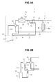
- a rotary compressor 10 includes a compressor body 11 and an accumulator 12 attached to the compressor body 11 as a basic configuration.
- the rotary compressor 10 is incorporated in a refrigerant circuit RC illustrated in Figs. 2A and B .
- the compressor body 11 includes an airtight container 110.
- the airtight container 110 has a cylindrical container body 111, and an upper lid 112a and a lower lid 112b that cover the container body 111.
- a refrigerant compression unit 115 and an electric motor 113 are housed in the airtight container 110.
- the refrigerant compression unit 115 includes a first refrigerant compression unit 115a and a second refrigerant compression unit 115b that are two refrigerant compression units vertically arranged in two stages.
- Each of the first refrigerant compression unit 115a and the second refrigerant compression unit 115b includes a cylinder 116 and a rotary piston 117 as a rotor that is housed in the cylinder 116.
- the rotary piston 117 on the first refrigerant compression unit 115a side and the rotary piston 117 on the second refrigerant compression unit 115b side are eccentrically fixed to a rotary drive shaft 113a of the electric motor 113 and rotatably driven with a phase of 180°.
- a refrigerant is suctioned into the first refrigerant compression unit 115a and the second refrigerant compression unit 115b from refrigerant intake openings 119a and 119b that are provided in a lower portion of the container body 111.
- a compressed refrigerant generated by the first refrigerant compression unit 115a is discharged into the airtight container 110 via an upper muffler 118a.
- a compressed refrigerant generated by the second refrigerant compression unit 115b is discharged into the airtight container 110 via a lower muffler 118b.
- Each compressed refrigerant is supplied to the refrigerant circuit RC from a refrigerant discharge pipe 114 that is provided in the upper lid 112a.
- refrigerant compression unit 115 in the case where there is no need to distinguish the first refrigerant compression unit 115a from the second refrigerant compression unit 115b, these are collectively referred to as the refrigerant compression unit 115.
- refrigerant intake openings 119a in the case where there is no need to distinguish the refrigerant intake openings 119a from the refrigerant intake openings 119b, these are collectively referred to as a refrigerant intake opening 119.
- the accumulator 12 includes an airtight container 120. Similar to the above-described airtight container 110, the airtight container 120 includes a cylindrical container body 121, and an upper lid 122a and a lower lid 122b that cover the container body 121. This airtight container 120 is arranged with an axis thereof being substantially perpendicular, that is, placed vertically, and is attached to a side of the compressor body 11 via fastening and fixing means such as a band, for example.
- a refrigerant return pipe 1C of the refrigerant circuit RC, which will be described below, and an injection pipe 50 (50a, 50b) are drawn into the accumulator 12 from the upper lid 122a.
- a refrigerant intake pipe 124 (124a, 124b) that is connected to each cylinder 116 in the refrigerant compression unit 115 (115a, 115b) is drawn from the lower lid 112b.
- two refrigerant compression units 115a and 115b are provided as the refrigerant compression unit 115, and each of them is actuated independently. Accordingly, the two refrigerant intake pipes 124a and 124b are used to respectively correspond to the refrigerant compression units 115a and 115b. In the case of two-stage compression, or in the case where one refrigerant compression unit 115 is provided, one refrigerant intake pipe 124 to be drawn is provided. In the case where there is no need to distinguish the two refrigerant intake pipes 124a and 124b from each other, these are collectively referred to as the refrigerant intake pipe 124.
- This refrigerant circuit RC is a circuit for an air conditioner of heat pump type that includes an outdoor unit 1 and an indoor unit 2.
- the outdoor unit 1 and the indoor unit 2 are connected by a liquid-side refrigerant pipe 1A and a gas-side refrigerant pipe 1B.
- one indoor unit 2 is provided.
- plural indoor units 2 may be connected in parallel between the liquid-side refrigerant pipe 1A and the gas-side refrigerant pipe 1B.
- the outdoor unit 1 is provided with the rotary compressor 10 having the above configuration, a four-way valve 20, an outdoor heat exchanger 30, an outdoor blowing fan 30a, an outdoor expansion valve 31, and the injection pipe 50.
- the indoor unit 2 is provided with an indoor heat exchanger 40, an indoor blowing fan 40a, and an indoor expansion valve 41.
- the four-way valve 20 is switched as illustrated by chain lines in Fig. 2A .
- the outdoor expansion valve 31 and the indoor expansion valve 41 are adjusted at specified opening degrees by a controller, which is not illustrated.
- a gaseous refrigerant at a high temperature and high pressure that is generated in the compressor body 11 and discharged from the refrigerant discharge pipe 114 is delivered to the indoor heat exchanger 40 via the four-way valve 20 and the gas-side refrigerant pipe 1B.
- This gaseous refrigerant at the high temperature and the high pressure is cooled through heat exchange with indoor air, and is decompressed at the indoor expansion valve 41.
- the refrigerant is returned to the outdoor unit 1 side via the liquid-side refrigerant pipe 1A, and is decompressed at the outdoor expansion valve 31. In this way, the refrigerant turns into a gas-liquid two-phase refrigerant at low pressure.
- This gas-liquid two-phase refrigerant is heated and evaporated through heat exchange with outdoor air in the outdoor heat exchanger 30 and turns into a low-pressure refrigerant.
- This low-pressure refrigerant enters the accumulator 12 from the refrigerant return pipe 1C through the four-way valve 20 and undergoes gas-liquid separation.
- the gaseous refrigerant after the gas-liquid separation is supplied to the refrigerant compression unit 115 via the refrigerant intake pipe 124.
- the indoor heat exchanger 40 acts as a condenser
- the outdoor heat exchanger 30 acts as an evaporator.
- the four-way valve 20 is switched as illustrated by solid lines in Fig. 2A .
- the outdoor expansion valve 31 is fully opened, and the indoor expansion valve 41 is adjusted at a specified opening degree by the controller, which is not illustrated.
- the gaseous refrigerant at a high temperature and high pressure that is generated in the compressor body 11 and discharged from the refrigerant discharge pipe 114 is delivered to the outdoor heat exchanger 30 via the four-way valve 20.
- This gaseous refrigerant at the high temperature and the high pressure is cooled through heat exchange with outdoor air and turns into a liquefied refrigerant at high pressure.
- This liquefied refrigerant reaches the indoor unit 2 via the liquid-side refrigerant pipe 1A, and is decompressed at the indoor expansion valve 41. In this way, the refrigerant turns into a gas-liquid two-phase refrigerant.
- This gas-liquid two-phase refrigerant is evaporated through heat exchange with indoor air in the indoor heat exchanger 40 and turns into a gaseous refrigerant at low pressure.
- This gaseous refrigerant is returned to the outdoor unit 1 side via the gas-side refrigerant pipe 1B, enters the accumulator 12 from the refrigerant return pipe 1C through the four-way valve 20, and undergoes gas-liquid separation.
- the gaseous refrigerant after the gas-liquid separation is supplied to the refrigerant compression unit 115 via the refrigerant intake pipe 124.
- the indoor heat exchanger 40 acts as an evaporator
- the outdoor heat exchanger 30 acts as a condenser.
- the injection pipe 50 is branched from the liquid-side refrigerant pipe 1A at a position of the liquid-side refrigerant pipe 1A that is on an upstream side of the outdoor expansion valve 31 during the heating operation and on a downstream side the outdoor expansion valve 31 during the cooling operation.
- the injection pipe 50 runs through a double-pipe heat exchanger 32 for injection in which heat exchange between the refrigerant in the injection pipe 50 and the refrigerant in the liquid-side refrigerant pipe 1A is carried out, and reaches the accumulator 12.
- the injection pipe 50 is provided with a solenoid valve 53 for injection, an opening degree of which can be adjusted, and a switching valve 52 for an injection refrigerant.
- the injection pipe 50 may be drawn from a gas-liquid separator 21 that is provided in the refrigerant discharge pipe 114 arranged between the compressor body 11 and the four-way valve 20.
- the accumulator 12 is provided with a filter 126 and a gas-liquid separation plate 127.
- the filter 126 is formed of a wire net or the like, for example, and removes foreign substances contained in the refrigerant.
- the filter 126 is arranged on an upper side, and the gas-liquid separation plate 127 is arranged on a lower side thereof.
- the refrigerant supplied from the refrigerant return pipe 1C undergoes the gas-liquid separation in the gas-liquid separation plate 127.
- a liquid refrigerant is reserved in a state of containing refrigerator oil in a lower section of the accumulator 12.
- the gaseous refrigerant is reserved in an upper section thereof.
- a portion in which the liquid refrigerant is reserved is referred to as a liquid refrigerant reservoir 120b, and a portion in which the gaseous refrigerant is reserved is referred to as a refrigerant gas space 120a as a matter of convenience.
- the refrigerant intake pipes 124a and 124b penetrate the lower lid 122b, are erected substantially perpendicularly, and extend to the refrigerant gas space 120a.
- respective suction openings 129a and 129b of the refrigerant intake pipes 124a and 124b are opened.
- Refrigerator oil return holes 125 with small diameters are perforated in portions of the refrigerant intake pipes 124a and 124b that are soaked in the liquid refrigerant reservoir 120b. It should be noted that, in the case where there is no need to distinguish the suction openings 129a and 129b from each other, these are collectively referred to as a suction opening 129.
- the injection pipes 50a and 50b are drawn from the upper lid 122a in the accumulator 12 such that the injection pipes 50a and 50b penetrate the filter 126 and the gas-liquid separation plate 127 and that discharge openings 51a and 51b of the injection pipes 50a and 50b respectively face the suction openings 129a and 129b of the refrigerant intake pipe 124 in the refrigerant gas space 120a.
- two refrigerant intake pipes 124a and 124b are provided.
- the injection pipe 50 is branched into two at a specified position, which is not illustrated, and has the injection pipes 50a and 50b.
- These injection pipes 50a and 50b are drawn into the accumulator 12. It should be noted that, in the case where there is no need to distinguish the injection pipes 50a and 50b from each other, these are collectively referred to as the injection pipe 50. Similarly, in the case where there is no need to distinguish the discharge openings 51a and 51b from each other, these are collectively referred to as a discharge opening 51.
- the pressure of the refrigerant that has undergone the heat exchange with indoor air in the indoor heat exchanger 40 is lowered to a specified pressure at the indoor expansion valve 41. Then, the refrigerant is returned to the outdoor unit 1 side via the liquid-side refrigerant pipe 1A.
- the switching valve 52 By turning on (i.e., opening) the switching valve 52, some of the refrigerant in the liquid-side refrigerant pipe 1A flows through the injection pipe 50, is decompressed at the solenoid valve 53 for injection, and passes through the double-pipe heat exchanger 32 for injection. In this way, the heat exchange between the refrigerant in the injection pipe 50 and the refrigerant in the liquid-side refrigerant pipe 1A is carried out. Thereafter, the refrigerant in the injection pipe 50 is injected at high speed from the discharge opening 51 of the injection pipe 50 into the accumulator 12.
- the injection refrigerant is injected at high speed from the discharge opening 51 of the injection pipe 50 toward the suction opening 129 of the refrigerant intake pipe 124, as described above. Accordingly, static pressure around the suction opening of the refrigerant intake pipe 124 is lowered. As a result, the gaseous refrigerant in the accumulator 12 is drawn into the refrigerant intake pipe 124.
- the injection refrigerant may be a gaseous refrigerant, it is preferably a liquid refrigerant. Since the inside of the compression chamber is cooled by injection of the liquid refrigerant, an increase in a discharge temperature can be suppressed.
- the discharge opening 51 of the injection pipe 50 and the suction opening 129 of the refrigerant intake pipe 124 may face each other with an appropriate distance under a condition that the ejector effect can be obtained.
- a pipe end on the discharge opening 51 side of the injection pipe 50 may be inserted into the refrigerant intake pipe 124.
- a throttle portion (a first throttle portion) 141 with a reduced diameter at the pipe end on the discharge opening 51 side of the injection pipe 50 so as to form the pipe end on the discharge opening 51 side in a nozzle shape.
- a throttle portion (a second throttle portion) 142 with a reduced diameter may be provided in a part of the refrigerant intake pipe 124.
- a flow velocity of the refrigerant is increased in the throttle portion 142, and thus, the static pressure around the suction opening of the refrigerant intake pipe 124 can be further lowered.
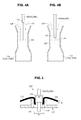
- the injection pipe 50 penetrates the filter 126 and the gas-liquid separation plate 127 and is drawn into the refrigerant gas space 120a. If a clearance is generated in this penetrated portion, foreign substances may enter the reservoir of the accumulator 12.
- This sealing means 130 includes a first sealing member 131, a cylindrical second sealing member 132, and a peripheral edge portion 133 of a through hole of the filter 126.
- the first sealing member 131 is formed in an annular shape toward the filter 126 side around a through hole of the gas-liquid separation plate 127.
- the second sealing member 132 is fixed to the injection pipe 50 side.
- the peripheral edge portion 133 of the through hole of the filter 126 is interposed between the first sealing member 131 and the second sealing member 132.
- the first sealing member 131 may be a cylindrical body that is brazed to the gas-liquid separation plate 127 and formed of a copper material, for example. However, in terms of easiness of processing, the first sealing member 131 is preferably an annular raised piece that is integrally formed with the gas-liquid separation plate 127 by burring.
- the second sealing member 132 may be a cylindrical body that is brazed to the injection pipe 50 and formed of the copper material, for example.
- an inner diameter of the first sealing member 131 is denoted by ⁇ 1
- an outer diameter of the second sealing member 132 is denoted by ⁇ 2
- a thickness of the filter is denoted by T
- the inner diameter ⁇ 1 of the first sealing member 131 and the outer diameter ⁇ 2 of the second sealing member 132 are defined as ( ⁇ 1 - ⁇ 2) ⁇ T.
- the second sealing member 132 is pressed into the first sealing member 131 such that the peripheral edge portion 133 of the through hole of the filter 126 is interposed between the first sealing member 131 and the second sealing member 132.
- the clearance in the penetrated portion of the injection pipe 50 can be sealed.
Landscapes
- Engineering & Computer Science (AREA)
- Mechanical Engineering (AREA)
- General Engineering & Computer Science (AREA)
- Physics & Mathematics (AREA)
- Thermal Sciences (AREA)
- Chemical & Material Sciences (AREA)
- Analytical Chemistry (AREA)
- Power Engineering (AREA)
- Applications Or Details Of Rotary Compressors (AREA)
Applications Claiming Priority (1)
| Application Number | Priority Date | Filing Date | Title |
|---|---|---|---|
| JP2014067535A JP6164427B2 (ja) | 2014-03-28 | 2014-03-28 | ロータリ圧縮機 |
Publications (2)
| Publication Number | Publication Date |
|---|---|
| EP2924295A1 true EP2924295A1 (de) | 2015-09-30 |
| EP2924295B1 EP2924295B1 (de) | 2018-05-02 |
Family
ID=52784970
Family Applications (1)
| Application Number | Title | Priority Date | Filing Date |
|---|---|---|---|
| EP15161483.1A Not-in-force EP2924295B1 (de) | 2014-03-28 | 2015-03-27 | Kühlkreislauf |
Country Status (5)
| Country | Link |
|---|---|
| US (1) | US9664191B2 (de) |
| EP (1) | EP2924295B1 (de) |
| JP (1) | JP6164427B2 (de) |
| CN (1) | CN104948461B (de) |
| AU (1) | AU2015201553B2 (de) |
Families Citing this family (10)
| Publication number | Priority date | Publication date | Assignee | Title |
|---|---|---|---|---|
| US9976785B2 (en) * | 2014-05-15 | 2018-05-22 | Lennox Industries Inc. | Liquid line charge compensator |
| US10330358B2 (en) | 2014-05-15 | 2019-06-25 | Lennox Industries Inc. | System for refrigerant pressure relief in HVAC systems |
| WO2016013077A1 (ja) * | 2014-07-23 | 2016-01-28 | 三菱電機株式会社 | 冷凍サイクル装置 |
| CN105674435B (zh) * | 2016-01-25 | 2018-11-02 | 珠海格力电器股份有限公司 | 一种空调室外机的冷媒灌注方法 |
| CN109477475B (zh) * | 2016-07-14 | 2022-06-17 | 大金工业株式会社 | 具有消声功能的压缩机 |
| JP6704526B2 (ja) * | 2017-07-25 | 2020-06-03 | 三菱電機株式会社 | 冷凍サイクル装置 |
| WO2019142408A1 (ja) * | 2018-01-18 | 2019-07-25 | 東芝キヤリア株式会社 | 圧縮機および冷凍サイクル装置 |
| US10663199B2 (en) | 2018-04-19 | 2020-05-26 | Lennox Industries Inc. | Method and apparatus for common manifold charge compensator |
| US10830514B2 (en) | 2018-06-21 | 2020-11-10 | Lennox Industries Inc. | Method and apparatus for charge compensator reheat valve |
| JP7215530B1 (ja) * | 2021-07-26 | 2023-01-31 | 株式会社富士通ゼネラル | 密閉型圧縮機 |
Citations (4)
| Publication number | Priority date | Publication date | Assignee | Title |
|---|---|---|---|---|
| EP0935106A2 (de) * | 1998-02-06 | 1999-08-11 | SANYO ELECTRIC Co., Ltd. | Kältevorrichtung mit mehrstufiger Verdichtung und die Vorrichtung verwendender Kühlschrank |
| WO2003060324A1 (en) * | 2001-12-28 | 2003-07-24 | Lg Electronics Inc. | Compressor having vibration reducing structure |
| EP2042740A2 (de) * | 2007-09-25 | 2009-04-01 | Fujitsu General Limited | Zweistufiger Rotationsverdichter |
| JP2013245837A (ja) | 2012-05-23 | 2013-12-09 | Daikin Industries Ltd | 冷凍装置 |
Family Cites Families (15)
| Publication number | Priority date | Publication date | Assignee | Title |
|---|---|---|---|---|
| US3167930A (en) * | 1962-11-19 | 1965-02-02 | Freightliner Corp | Refrigeration system |
| US4215555A (en) * | 1978-10-02 | 1980-08-05 | Carrier Corporation | Hot gas defrost system |
| JPS57129286A (en) * | 1981-02-02 | 1982-08-11 | Hitachi Ltd | Rotary compressor |
| JPS58148290A (ja) * | 1982-02-26 | 1983-09-03 | Hitachi Ltd | スクロ−ル圧縮機を用いた冷凍装置 |
| JPS5925065U (ja) * | 1982-08-07 | 1984-02-16 | 松下冷機株式会社 | ヒ−トポンプ式空気調和機 |
| JPH065567Y2 (ja) * | 1986-05-09 | 1994-02-09 | 三洋電機株式会社 | 冷凍装置 |
| EP0882780A4 (de) * | 1995-12-28 | 2000-08-16 | Daikin Ind Ltd | Kältemaschinenöl und kältemaschine zur verwendung desselben |
| JPH1137578A (ja) * | 1997-07-16 | 1999-02-12 | Toshiba Corp | 空気調和装置 |
| JP2000337261A (ja) * | 1999-05-26 | 2000-12-05 | Funai Electric Co Ltd | 圧縮機 |
| JP2001330343A (ja) * | 2000-05-19 | 2001-11-30 | Fujitsu General Ltd | 圧縮機用アキュムレータ |
| KR100531902B1 (ko) * | 2003-06-12 | 2005-11-29 | 엘지전자 주식회사 | 로터리 압축기의 어큐뮬레이터 |
| CN1862021A (zh) * | 2005-05-09 | 2006-11-15 | 乐金电子(天津)电器有限公司 | 旋转式双气缸压缩机气液分离器的结构 |
| CN2856497Y (zh) * | 2005-07-12 | 2007-01-10 | 乐金电子(天津)电器有限公司 | 压缩机的储液罐的连接结构 |
| KR100747496B1 (ko) * | 2006-11-27 | 2007-08-08 | 삼성전자주식회사 | 로터리 압축기 및 그 제어방법 그리고 이를 이용한공기조화기 |
| JP2013096602A (ja) * | 2011-10-28 | 2013-05-20 | Panasonic Corp | 冷凍サイクル装置 |
-
2014
- 2014-03-28 JP JP2014067535A patent/JP6164427B2/ja active Active
-
2015
- 2015-03-25 AU AU2015201553A patent/AU2015201553B2/en not_active Ceased
- 2015-03-26 US US14/669,774 patent/US9664191B2/en not_active Expired - Fee Related
- 2015-03-27 CN CN201510142436.9A patent/CN104948461B/zh not_active Expired - Fee Related
- 2015-03-27 EP EP15161483.1A patent/EP2924295B1/de not_active Not-in-force
Patent Citations (4)
| Publication number | Priority date | Publication date | Assignee | Title |
|---|---|---|---|---|
| EP0935106A2 (de) * | 1998-02-06 | 1999-08-11 | SANYO ELECTRIC Co., Ltd. | Kältevorrichtung mit mehrstufiger Verdichtung und die Vorrichtung verwendender Kühlschrank |
| WO2003060324A1 (en) * | 2001-12-28 | 2003-07-24 | Lg Electronics Inc. | Compressor having vibration reducing structure |
| EP2042740A2 (de) * | 2007-09-25 | 2009-04-01 | Fujitsu General Limited | Zweistufiger Rotationsverdichter |
| JP2013245837A (ja) | 2012-05-23 | 2013-12-09 | Daikin Industries Ltd | 冷凍装置 |
Also Published As
| Publication number | Publication date |
|---|---|
| US20150275895A1 (en) | 2015-10-01 |
| US9664191B2 (en) | 2017-05-30 |
| EP2924295B1 (de) | 2018-05-02 |
| AU2015201553B2 (en) | 2018-11-08 |
| AU2015201553A1 (en) | 2015-10-15 |
| JP6164427B2 (ja) | 2017-07-19 |
| CN104948461A (zh) | 2015-09-30 |
| CN104948461B (zh) | 2018-12-11 |
| JP2015190668A (ja) | 2015-11-02 |
Similar Documents
| Publication | Publication Date | Title |
|---|---|---|
| EP2924295B1 (de) | Kühlkreislauf | |
| TWI656310B (zh) | 高壓壓縮機及具有該高壓壓縮機的冷凍機 | |
| KR101280155B1 (ko) | 히트 펌프 장치, 2단 압축기 및 히트 펌프 장치의 운전 방법 | |
| KR101208141B1 (ko) | 스크롤 압축기 | |
| JP4183021B1 (ja) | 圧縮機および冷凍装置 | |
| CN102022332A (zh) | 能力控制式双缸旋转压缩机及其控制方法 | |
| KR101275921B1 (ko) | 밀폐형 압축기 | |
| WO2014083901A1 (ja) | 圧縮機、冷凍サイクル装置およびヒートポンプ給湯装置 | |
| KR20120007337A (ko) | 압축기 | |
| KR101212642B1 (ko) | 압축기 용량 제어 조작 기구, 및 그것을 구비한 공기 조화 장치 | |
| CN101344091A (zh) | 旋转式压缩机的冷媒充注装置及其控制方法 | |
| KR102103362B1 (ko) | 스크롤 압축기 및 이를 포함하는 공기조화기 | |
| CN101344089B (zh) | 多汽缸旋转压缩机 | |
| JP5515289B2 (ja) | 冷凍装置 | |
| JP2006283592A (ja) | 流体機械 | |
| JP2010236726A (ja) | ヒートポンプ装置 | |
| EP3492748B1 (de) | Kompressor sowie kältevorrichtung mit kühl- und heizfunktion und kältevorrichtung nur mit kühlfunktion damit | |
| KR100504923B1 (ko) | 히트펌프용 어큐뮬레이터의 유체혼합장치 | |
| JP5835299B2 (ja) | 冷凍装置 | |
| KR100767683B1 (ko) | 공기조화기 | |
| JP5892261B2 (ja) | 冷凍サイクル装置およびヒートポンプ給湯装置 | |
| JPH11337197A (ja) | 冷凍サイクル装置 | |
| JP2003004342A (ja) | 空気調和機の冷凍サイクル | |
| JPH0122555B2 (de) |
Legal Events
| Date | Code | Title | Description |
|---|---|---|---|
| PUAI | Public reference made under article 153(3) epc to a published international application that has entered the european phase |
Free format text: ORIGINAL CODE: 0009012 |
|
| AK | Designated contracting states |
Kind code of ref document: A1 Designated state(s): AL AT BE BG CH CY CZ DE DK EE ES FI FR GB GR HR HU IE IS IT LI LT LU LV MC MK MT NL NO PL PT RO RS SE SI SK SM TR |
|
| AX | Request for extension of the european patent |
Extension state: BA ME |
|
| 17P | Request for examination filed |
Effective date: 20160329 |
|
| RBV | Designated contracting states (corrected) |
Designated state(s): AL AT BE BG CH CY CZ DE DK EE ES FI FR GB GR HR HU IE IS IT LI LT LU LV MC MK MT NL NO PL PT RO RS SE SI SK SM TR |
|
| STAA | Information on the status of an ep patent application or granted ep patent |
Free format text: STATUS: EXAMINATION IS IN PROGRESS |
|
| 17Q | First examination report despatched |
Effective date: 20170418 |
|
| GRAP | Despatch of communication of intention to grant a patent |
Free format text: ORIGINAL CODE: EPIDOSNIGR1 |
|
| STAA | Information on the status of an ep patent application or granted ep patent |
Free format text: STATUS: GRANT OF PATENT IS INTENDED |
|
| RAP1 | Party data changed (applicant data changed or rights of an application transferred) |
Owner name: FUJITSU GENERAL LIMITED |
|
| INTG | Intention to grant announced |
Effective date: 20171010 |
|
| GRAS | Grant fee paid |
Free format text: ORIGINAL CODE: EPIDOSNIGR3 |
|
| GRAJ | Information related to disapproval of communication of intention to grant by the applicant or resumption of examination proceedings by the epo deleted |
Free format text: ORIGINAL CODE: EPIDOSDIGR1 |
|
| GRAL | Information related to payment of fee for publishing/printing deleted |
Free format text: ORIGINAL CODE: EPIDOSDIGR3 |
|
| STAA | Information on the status of an ep patent application or granted ep patent |
Free format text: STATUS: EXAMINATION IS IN PROGRESS |
|
| GRAR | Information related to intention to grant a patent recorded |
Free format text: ORIGINAL CODE: EPIDOSNIGR71 |
|
| STAA | Information on the status of an ep patent application or granted ep patent |
Free format text: STATUS: GRANT OF PATENT IS INTENDED |
|
| INTC | Intention to grant announced (deleted) | ||
| GRAA | (expected) grant |
Free format text: ORIGINAL CODE: 0009210 |
|
| STAA | Information on the status of an ep patent application or granted ep patent |
Free format text: STATUS: THE PATENT HAS BEEN GRANTED |
|
| INTG | Intention to grant announced |
Effective date: 20180321 |
|
| AK | Designated contracting states |
Kind code of ref document: B1 Designated state(s): AL AT BE BG CH CY CZ DE DK EE ES FI FR GB GR HR HU IE IS IT LI LT LU LV MC MK MT NL NO PL PT RO RS SE SI SK SM TR |
|
| REG | Reference to a national code |
Ref country code: GB Ref legal event code: FG4D |
|
| REG | Reference to a national code |
Ref country code: CH Ref legal event code: EP Ref country code: AT Ref legal event code: REF Ref document number: 995560 Country of ref document: AT Kind code of ref document: T Effective date: 20180515 |
|
| REG | Reference to a national code |
Ref country code: DE Ref legal event code: R096 Ref document number: 602015010582 Country of ref document: DE Ref country code: IE Ref legal event code: FG4D |
|
| REG | Reference to a national code |
Ref country code: NL Ref legal event code: MP Effective date: 20180502 |
|
| REG | Reference to a national code |
Ref country code: LT Ref legal event code: MG4D |
|
| PG25 | Lapsed in a contracting state [announced via postgrant information from national office to epo] |
Ref country code: SE Free format text: LAPSE BECAUSE OF FAILURE TO SUBMIT A TRANSLATION OF THE DESCRIPTION OR TO PAY THE FEE WITHIN THE PRESCRIBED TIME-LIMIT Effective date: 20180502 Ref country code: BG Free format text: LAPSE BECAUSE OF FAILURE TO SUBMIT A TRANSLATION OF THE DESCRIPTION OR TO PAY THE FEE WITHIN THE PRESCRIBED TIME-LIMIT Effective date: 20180802 Ref country code: FI Free format text: LAPSE BECAUSE OF FAILURE TO SUBMIT A TRANSLATION OF THE DESCRIPTION OR TO PAY THE FEE WITHIN THE PRESCRIBED TIME-LIMIT Effective date: 20180502 Ref country code: LT Free format text: LAPSE BECAUSE OF FAILURE TO SUBMIT A TRANSLATION OF THE DESCRIPTION OR TO PAY THE FEE WITHIN THE PRESCRIBED TIME-LIMIT Effective date: 20180502 Ref country code: NO Free format text: LAPSE BECAUSE OF FAILURE TO SUBMIT A TRANSLATION OF THE DESCRIPTION OR TO PAY THE FEE WITHIN THE PRESCRIBED TIME-LIMIT Effective date: 20180802 Ref country code: ES Free format text: LAPSE BECAUSE OF FAILURE TO SUBMIT A TRANSLATION OF THE DESCRIPTION OR TO PAY THE FEE WITHIN THE PRESCRIBED TIME-LIMIT Effective date: 20180502 |
|
| PG25 | Lapsed in a contracting state [announced via postgrant information from national office to epo] |
Ref country code: HR Free format text: LAPSE BECAUSE OF FAILURE TO SUBMIT A TRANSLATION OF THE DESCRIPTION OR TO PAY THE FEE WITHIN THE PRESCRIBED TIME-LIMIT Effective date: 20180502 Ref country code: GR Free format text: LAPSE BECAUSE OF FAILURE TO SUBMIT A TRANSLATION OF THE DESCRIPTION OR TO PAY THE FEE WITHIN THE PRESCRIBED TIME-LIMIT Effective date: 20180803 Ref country code: NL Free format text: LAPSE BECAUSE OF FAILURE TO SUBMIT A TRANSLATION OF THE DESCRIPTION OR TO PAY THE FEE WITHIN THE PRESCRIBED TIME-LIMIT Effective date: 20180502 Ref country code: LV Free format text: LAPSE BECAUSE OF FAILURE TO SUBMIT A TRANSLATION OF THE DESCRIPTION OR TO PAY THE FEE WITHIN THE PRESCRIBED TIME-LIMIT Effective date: 20180502 Ref country code: RS Free format text: LAPSE BECAUSE OF FAILURE TO SUBMIT A TRANSLATION OF THE DESCRIPTION OR TO PAY THE FEE WITHIN THE PRESCRIBED TIME-LIMIT Effective date: 20180502 |
|
| REG | Reference to a national code |
Ref country code: AT Ref legal event code: MK05 Ref document number: 995560 Country of ref document: AT Kind code of ref document: T Effective date: 20180502 |
|
| PG25 | Lapsed in a contracting state [announced via postgrant information from national office to epo] |
Ref country code: RO Free format text: LAPSE BECAUSE OF FAILURE TO SUBMIT A TRANSLATION OF THE DESCRIPTION OR TO PAY THE FEE WITHIN THE PRESCRIBED TIME-LIMIT Effective date: 20180502 Ref country code: SK Free format text: LAPSE BECAUSE OF FAILURE TO SUBMIT A TRANSLATION OF THE DESCRIPTION OR TO PAY THE FEE WITHIN THE PRESCRIBED TIME-LIMIT Effective date: 20180502 Ref country code: CZ Free format text: LAPSE BECAUSE OF FAILURE TO SUBMIT A TRANSLATION OF THE DESCRIPTION OR TO PAY THE FEE WITHIN THE PRESCRIBED TIME-LIMIT Effective date: 20180502 Ref country code: EE Free format text: LAPSE BECAUSE OF FAILURE TO SUBMIT A TRANSLATION OF THE DESCRIPTION OR TO PAY THE FEE WITHIN THE PRESCRIBED TIME-LIMIT Effective date: 20180502 Ref country code: AT Free format text: LAPSE BECAUSE OF FAILURE TO SUBMIT A TRANSLATION OF THE DESCRIPTION OR TO PAY THE FEE WITHIN THE PRESCRIBED TIME-LIMIT Effective date: 20180502 Ref country code: DK Free format text: LAPSE BECAUSE OF FAILURE TO SUBMIT A TRANSLATION OF THE DESCRIPTION OR TO PAY THE FEE WITHIN THE PRESCRIBED TIME-LIMIT Effective date: 20180502 Ref country code: PL Free format text: LAPSE BECAUSE OF FAILURE TO SUBMIT A TRANSLATION OF THE DESCRIPTION OR TO PAY THE FEE WITHIN THE PRESCRIBED TIME-LIMIT Effective date: 20180502 |
|
| REG | Reference to a national code |
Ref country code: DE Ref legal event code: R097 Ref document number: 602015010582 Country of ref document: DE |
|
| PG25 | Lapsed in a contracting state [announced via postgrant information from national office to epo] |
Ref country code: IT Free format text: LAPSE BECAUSE OF FAILURE TO SUBMIT A TRANSLATION OF THE DESCRIPTION OR TO PAY THE FEE WITHIN THE PRESCRIBED TIME-LIMIT Effective date: 20180502 Ref country code: SM Free format text: LAPSE BECAUSE OF FAILURE TO SUBMIT A TRANSLATION OF THE DESCRIPTION OR TO PAY THE FEE WITHIN THE PRESCRIBED TIME-LIMIT Effective date: 20180502 |
|
| PLBE | No opposition filed within time limit |
Free format text: ORIGINAL CODE: 0009261 |
|
| STAA | Information on the status of an ep patent application or granted ep patent |
Free format text: STATUS: NO OPPOSITION FILED WITHIN TIME LIMIT |
|
| 26N | No opposition filed |
Effective date: 20190205 |
|
| PG25 | Lapsed in a contracting state [announced via postgrant information from national office to epo] |
Ref country code: SI Free format text: LAPSE BECAUSE OF FAILURE TO SUBMIT A TRANSLATION OF THE DESCRIPTION OR TO PAY THE FEE WITHIN THE PRESCRIBED TIME-LIMIT Effective date: 20180502 |
|
| PG25 | Lapsed in a contracting state [announced via postgrant information from national office to epo] |
Ref country code: MC Free format text: LAPSE BECAUSE OF FAILURE TO SUBMIT A TRANSLATION OF THE DESCRIPTION OR TO PAY THE FEE WITHIN THE PRESCRIBED TIME-LIMIT Effective date: 20180502 |
|
| REG | Reference to a national code |
Ref country code: CH Ref legal event code: PL |
|
| PG25 | Lapsed in a contracting state [announced via postgrant information from national office to epo] |
Ref country code: LU Free format text: LAPSE BECAUSE OF NON-PAYMENT OF DUE FEES Effective date: 20190327 Ref country code: AL Free format text: LAPSE BECAUSE OF FAILURE TO SUBMIT A TRANSLATION OF THE DESCRIPTION OR TO PAY THE FEE WITHIN THE PRESCRIBED TIME-LIMIT Effective date: 20180502 |
|
| REG | Reference to a national code |
Ref country code: BE Ref legal event code: MM Effective date: 20190331 |
|
| PG25 | Lapsed in a contracting state [announced via postgrant information from national office to epo] |
Ref country code: LI Free format text: LAPSE BECAUSE OF NON-PAYMENT OF DUE FEES Effective date: 20190331 Ref country code: IE Free format text: LAPSE BECAUSE OF NON-PAYMENT OF DUE FEES Effective date: 20190327 Ref country code: CH Free format text: LAPSE BECAUSE OF NON-PAYMENT OF DUE FEES Effective date: 20190331 |
|
| PG25 | Lapsed in a contracting state [announced via postgrant information from national office to epo] |
Ref country code: BE Free format text: LAPSE BECAUSE OF NON-PAYMENT OF DUE FEES Effective date: 20190331 |
|
| PG25 | Lapsed in a contracting state [announced via postgrant information from national office to epo] |
Ref country code: TR Free format text: LAPSE BECAUSE OF FAILURE TO SUBMIT A TRANSLATION OF THE DESCRIPTION OR TO PAY THE FEE WITHIN THE PRESCRIBED TIME-LIMIT Effective date: 20180502 |
|
| PG25 | Lapsed in a contracting state [announced via postgrant information from national office to epo] |
Ref country code: MT Free format text: LAPSE BECAUSE OF NON-PAYMENT OF DUE FEES Effective date: 20190327 Ref country code: PT Free format text: LAPSE BECAUSE OF FAILURE TO SUBMIT A TRANSLATION OF THE DESCRIPTION OR TO PAY THE FEE WITHIN THE PRESCRIBED TIME-LIMIT Effective date: 20180903 |
|
| PG25 | Lapsed in a contracting state [announced via postgrant information from national office to epo] |
Ref country code: CY Free format text: LAPSE BECAUSE OF FAILURE TO SUBMIT A TRANSLATION OF THE DESCRIPTION OR TO PAY THE FEE WITHIN THE PRESCRIBED TIME-LIMIT Effective date: 20180502 |
|
| PG25 | Lapsed in a contracting state [announced via postgrant information from national office to epo] |
Ref country code: IS Free format text: LAPSE BECAUSE OF FAILURE TO SUBMIT A TRANSLATION OF THE DESCRIPTION OR TO PAY THE FEE WITHIN THE PRESCRIBED TIME-LIMIT Effective date: 20180902 |
|
| PG25 | Lapsed in a contracting state [announced via postgrant information from national office to epo] |
Ref country code: HU Free format text: LAPSE BECAUSE OF FAILURE TO SUBMIT A TRANSLATION OF THE DESCRIPTION OR TO PAY THE FEE WITHIN THE PRESCRIBED TIME-LIMIT; INVALID AB INITIO Effective date: 20150327 |
|
| PGFP | Annual fee paid to national office [announced via postgrant information from national office to epo] |
Ref country code: GB Payment date: 20220203 Year of fee payment: 8 Ref country code: DE Payment date: 20220203 Year of fee payment: 8 |
|
| PGFP | Annual fee paid to national office [announced via postgrant information from national office to epo] |
Ref country code: FR Payment date: 20220209 Year of fee payment: 8 |
|
| PG25 | Lapsed in a contracting state [announced via postgrant information from national office to epo] |
Ref country code: MK Free format text: LAPSE BECAUSE OF FAILURE TO SUBMIT A TRANSLATION OF THE DESCRIPTION OR TO PAY THE FEE WITHIN THE PRESCRIBED TIME-LIMIT Effective date: 20180502 |
|
| REG | Reference to a national code |
Ref country code: DE Ref legal event code: R119 Ref document number: 602015010582 Country of ref document: DE |
|
| GBPC | Gb: european patent ceased through non-payment of renewal fee |
Effective date: 20230327 |
|
| PG25 | Lapsed in a contracting state [announced via postgrant information from national office to epo] |
Ref country code: GB Free format text: LAPSE BECAUSE OF NON-PAYMENT OF DUE FEES Effective date: 20230327 |
|
| PG25 | Lapsed in a contracting state [announced via postgrant information from national office to epo] |
Ref country code: GB Free format text: LAPSE BECAUSE OF NON-PAYMENT OF DUE FEES Effective date: 20230327 Ref country code: FR Free format text: LAPSE BECAUSE OF NON-PAYMENT OF DUE FEES Effective date: 20230331 Ref country code: DE Free format text: LAPSE BECAUSE OF NON-PAYMENT OF DUE FEES Effective date: 20231003 |