EP2924571B1 - Cloud-manifest-konfigurationsverwaltungssystem - Google Patents
Cloud-manifest-konfigurationsverwaltungssystem Download PDFInfo
- Publication number
- EP2924571B1 EP2924571B1 EP15160944.3A EP15160944A EP2924571B1 EP 2924571 B1 EP2924571 B1 EP 2924571B1 EP 15160944 A EP15160944 A EP 15160944A EP 2924571 B1 EP2924571 B1 EP 2924571B1
- Authority
- EP
- European Patent Office
- Prior art keywords
- data
- manifest
- industrial
- cloud
- cloud platform
- Prior art date
- Legal status (The legal status is an assumption and is not a legal conclusion. Google has not performed a legal analysis and makes no representation as to the accuracy of the status listed.)
- Active
Links
Images









Classifications
-
- G—PHYSICS
- G05—CONTROLLING; REGULATING
- G05B—CONTROL OR REGULATING SYSTEMS IN GENERAL; FUNCTIONAL ELEMENTS OF SUCH SYSTEMS; MONITORING OR TESTING ARRANGEMENTS FOR SUCH SYSTEMS OR ELEMENTS
- G05B19/00—Program-control systems
- G05B19/02—Program-control systems electric
- G05B19/418—Total factory control, i.e. centrally controlling a plurality of machines, e.g. direct or distributed numerical control [DNC], flexible manufacturing systems [FMS], integrated manufacturing systems [IMS] or computer integrated manufacturing [CIM]
- G05B19/41865—Total factory control, i.e. centrally controlling a plurality of machines, e.g. direct or distributed numerical control [DNC], flexible manufacturing systems [FMS], integrated manufacturing systems [IMS] or computer integrated manufacturing [CIM] characterised by job scheduling, process planning, material flow
-
- H—ELECTRICITY
- H04—ELECTRIC COMMUNICATION TECHNIQUE
- H04L—TRANSMISSION OF DIGITAL INFORMATION, e.g. TELEGRAPHIC COMMUNICATION
- H04L67/00—Network arrangements or protocols for supporting network services or applications
- H04L67/01—Protocols
- H04L67/02—Protocols based on web technology, e.g. hypertext transfer protocol [HTTP]
-
- G—PHYSICS
- G06—COMPUTING OR CALCULATING; COUNTING
- G06F—ELECTRIC DIGITAL DATA PROCESSING
- G06F9/00—Arrangements for program control, e.g. control units
- G06F9/06—Arrangements for program control, e.g. control units using stored programs, i.e. using an internal store of processing equipment to receive or retain programs
- G06F9/46—Multiprogramming arrangements
- G06F9/50—Allocation of resources, e.g. of the central processing unit [CPU]
- G06F9/5061—Partitioning or combining of resources
- G06F9/5072—Grid computing
-
- G—PHYSICS
- G05—CONTROLLING; REGULATING
- G05B—CONTROL OR REGULATING SYSTEMS IN GENERAL; FUNCTIONAL ELEMENTS OF SUCH SYSTEMS; MONITORING OR TESTING ARRANGEMENTS FOR SUCH SYSTEMS OR ELEMENTS
- G05B19/00—Program-control systems
- G05B19/02—Program-control systems electric
- G05B19/18—Numerical control [NC], i.e. automatically operating machines, in particular machine tools, e.g. in a manufacturing environment, so as to execute positioning, movement or co-ordinated operations by means of program data in numerical form
-
- G—PHYSICS
- G05—CONTROLLING; REGULATING
- G05B—CONTROL OR REGULATING SYSTEMS IN GENERAL; FUNCTIONAL ELEMENTS OF SUCH SYSTEMS; MONITORING OR TESTING ARRANGEMENTS FOR SUCH SYSTEMS OR ELEMENTS
- G05B19/00—Program-control systems
- G05B19/02—Program-control systems electric
- G05B19/418—Total factory control, i.e. centrally controlling a plurality of machines, e.g. direct or distributed numerical control [DNC], flexible manufacturing systems [FMS], integrated manufacturing systems [IMS] or computer integrated manufacturing [CIM]
- G05B19/4185—Total factory control, i.e. centrally controlling a plurality of machines, e.g. direct or distributed numerical control [DNC], flexible manufacturing systems [FMS], integrated manufacturing systems [IMS] or computer integrated manufacturing [CIM] characterised by the network communication
-
- G—PHYSICS
- G06—COMPUTING OR CALCULATING; COUNTING
- G06F—ELECTRIC DIGITAL DATA PROCESSING
- G06F9/00—Arrangements for program control, e.g. control units
- G06F9/06—Arrangements for program control, e.g. control units using stored programs, i.e. using an internal store of processing equipment to receive or retain programs
- G06F9/46—Multiprogramming arrangements
- G06F9/54—Interprogram communication
-
- H—ELECTRICITY
- H04—ELECTRIC COMMUNICATION TECHNIQUE
- H04L—TRANSMISSION OF DIGITAL INFORMATION, e.g. TELEGRAPHIC COMMUNICATION
- H04L47/00—Traffic control in data switching networks
- H04L47/50—Queue scheduling
-
- Y—GENERAL TAGGING OF NEW TECHNOLOGICAL DEVELOPMENTS; GENERAL TAGGING OF CROSS-SECTIONAL TECHNOLOGIES SPANNING OVER SEVERAL SECTIONS OF THE IPC; TECHNICAL SUBJECTS COVERED BY FORMER USPC CROSS-REFERENCE ART COLLECTIONS [XRACs] AND DIGESTS
- Y02—TECHNOLOGIES OR APPLICATIONS FOR MITIGATION OR ADAPTATION AGAINST CLIMATE CHANGE
- Y02P—CLIMATE CHANGE MITIGATION TECHNOLOGIES IN THE PRODUCTION OR PROCESSING OF GOODS
- Y02P90/00—Enabling technologies with a potential contribution to greenhouse gas [GHG] emissions mitigation
- Y02P90/02—Total factory control, e.g. smart factories, flexible manufacturing systems [FMS] or integrated manufacturing systems [IMS]
-
- Y—GENERAL TAGGING OF NEW TECHNOLOGICAL DEVELOPMENTS; GENERAL TAGGING OF CROSS-SECTIONAL TECHNOLOGIES SPANNING OVER SEVERAL SECTIONS OF THE IPC; TECHNICAL SUBJECTS COVERED BY FORMER USPC CROSS-REFERENCE ART COLLECTIONS [XRACs] AND DIGESTS
- Y02—TECHNOLOGIES OR APPLICATIONS FOR MITIGATION OR ADAPTATION AGAINST CLIMATE CHANGE
- Y02P—CLIMATE CHANGE MITIGATION TECHNOLOGIES IN THE PRODUCTION OR PROCESSING OF GOODS
- Y02P90/00—Enabling technologies with a potential contribution to greenhouse gas [GHG] emissions mitigation
- Y02P90/80—Management or planning
Definitions
- the subject matter disclosed herein relates generally to industrial data collection, and, more particularly, to an on-premise cloud agent that facilitates collection and upload of industrial data to a cloud-based storage and processing infrastructure.
- EP 2 704 401 A1 relates to deployment of cloud data storage farms for storing alarm, historical, and life automation data using an agent-based communication channel.
- a cloud-based infrastructure can facilitate gathering, transmitting, and remotely storing control and automation data and relating information.
- the infrastructure can collect the industrial data from data collectors in an industrial enterprise.
- a system for processing industrial data in a cloud platform comprising a queue management component configured to receive, at a cloud platform, a data packet from a cloud agent device residing at an industrial facility and assign industrial data contained in the data packet to a priority queue in the cloud platform, a manifest assembly repository configured to maintain a set of manifest assemblies that respectively define operations to be performed on industrial data received at the cloud platform, and a worker role component configured to identify a manifest assembly, of the set of manifest assemblies, based on header information contained in the data packet, and to process the industrial data in the priority queue in accordance with the manifest assembly.
- one or more embodiments provide a method for collecting and managing data in a cloud platform, comprising receiving, at a cloud platform by a system comprising at least one processor, a data packet from a data collection device located at an industrial plant, wherein the data packet comprises a data file containing industrial data and a header; assigning the industrial data to a priority queue on the cloud platform; identifying a manifest assembly, of a plurality of manifest assemblies stored in a manifest repository of the cloud platform, based on information read from the header; and processing the industrial data in the priority queue in accordance with the manifest assembly.
- a non-transitory computer-readable medium having stored thereon instructions that, in response to execution, cause a system to perform operations, the operations, comprising receiving, at a cloud platform, a data packet from a cloud agent device residing at an industrial site, wherein the data packet comprises a data file containing industrial data and header information; assigning the industrial data to a priority queue on the cloud platform; selecting, based on the header information, a manifest assembly from a plurality of manifest assemblies stored in a manifest repository of the cloud platform; and processing the industrial data in the priority queue according to processing instructions specified by the manifest assembly.
- the terms "component,” “system,” “platform,” “layer,” “controller,” “terminal,” “station,” “node,” “interface” are intended to refer to a computer-related entity or an entity related to, or that is part of, an operational apparatus with one or more specific functionalities, wherein such entities can be either hardware, a combination of hardware and software, software, or software in execution.
- a component can be, but is not limited to being, a process running on a processor, a processor, a hard disk drive, multiple storage drives (of optical or magnetic storage medium) including affixed (e.g., screwed or bolted) or removable affixed solid-state storage drives; an object; an executable; a thread of execution; a computer-executable program, and/or a computer.
- affixed e.g., screwed or bolted
- the components may communicate via local and/or remote processes such as in accordance with a signal having one or more data packets (e.g., data from one component interacting with another component in a local system, distributed system, and/or across a network such as the Internet with other systems via the signal).
- a component can be an apparatus with specific functionality provided by mechanical parts operated by electric or electronic circuitry which is operated by a software or a firmware application executed by a processor, wherein the processor can be internal or external to the apparatus and executes at least a part of the software or firmware application.
- a component can be an apparatus that provides specific functionality through electronic components without mechanical parts, the electronic components can include a processor therein to execute software or firmware that provides at least in part the functionality of the electronic components.
- interface(s) can include input/output (I/O) components as well as associated processor, application, or Application Programming Interface (API) components. While the foregoing examples are directed to aspects of a component, the exemplified aspects or features also apply to a system, platform, interface, layer, controller, terminal, and the like.
- I/O input/output
- API Application Programming Interface
- the terms "to infer” and “inference” refer generally to the process of reasoning about or inferring states of the system, environment, and/or user from a set of observations as captured via events and/or data. Inference can be employed to identify a specific context or action, or can generate a probability distribution over states, for example. The inference can be probabilistic-that is, the computation of a probability distribution over states of interest based on a consideration of data and events. Inference can also refer to techniques employed for composing higher-level events from a set of events and/or data. Such inference results in the construction of new events or actions from a set of observed events and/or stored event data, whether or not the events are correlated in close temporal proximity, and whether the events and data come from one or several event and data sources.
- the term "or” is intended to mean an inclusive “or” rather than an exclusive “or.” That is, unless specified otherwise, or clear from the context, the phrase “X employs A or B” is intended to mean any of the natural inclusive permutations. That is, the phrase “X employs A or B” is satisfied by any of the following instances: X employs A; X employs B; or X employs both A and B.
- the articles “a” and “an” as used in this application and the appended claims should generally be construed to mean “one or more” unless specified otherwise or clear from the context to be directed to a singular form.
- a “set” in the subject disclosure includes one or more elements or entities.
- a set of controllers includes one or more controllers; a set of data resources includes one or more data resources; etc.
- group refers to a collection of one or more entities; e.g., a group of nodes refers to one or more nodes.
- Industrial controllers and their associated I/O devices are central to the operation of modern automation systems. These controllers interact with field devices on the plant floor to control automated processes relating to such objectives as product manufacture, material handling, batch processing, supervisory control, and other such applications. Industrial controllers store and execute user-defined control programs to effect decision-making in connection with the controlled process. Such programs can include, but are not limited to, ladder logic, sequential function charts, function block diagrams, structured text, or other such programming structures.
- one or more embodiments of the present disclosure provide a cloud computing platform architecture that facilitates remote collection, storage, and processing of industrial data.
- the platform uses an agent-based architecture to gather industrial data from data sources at all levels of an industrial enterprise, including but not limited to industrial devices (e.g., controllers, drives, telemetry devices, etc.), data historians, data tables, business-level systems (e.g. enterprise resource planning systems, manufacturing execution systems, accounting systems, etc.), and other such data source.
- the cloud-based infrastructure can intelligently sort and organize the acquired data into priority message queues.
- Worker roles executing on the cloud platform determine how the queued data is to be processed based on manifests (e.g., system manifests, tag manifests, and metric manifests) stored in a customer-specific manifest assembly.
- manifests e.g., system manifests, tag manifests, and metric manifests
- Manifests define and implement customer-specific capabilities, applications, and preferences for processing collected data in the cloud.
- FIG. 1 illustrates a high-level overview of an industrial enterprise that leverages cloud-based services.
- the enterprise comprises one or more industrial facilities 104, each having a number of industrial devices 108 and 110 in use.
- the industrial devices 108 and 110 can make up one or more automation systems operating within the respective facilities 104.
- Exemplary automation systems can include, but are not limited to, batch control systems (e.g., mixing systems), continuous control systems (e.g., PID control systems), or discrete control systems.
- Industrial devices 108 and 110 can include such devices as industrial controllers (e.g., programmable logic controllers or other types of programmable automation controllers); field devices such as sensors and meters; motor drives; operator interfaces (e.g., human-machine interfaces, industrial monitors, graphic terminals, message displays, etc.); industrial robots, barcode markers and readers; vision system devices (e.g., vision cameras); smart welders; or other such industrial devices.
- industrial controllers e.g., programmable logic controllers or other types of programmable automation controllers
- field devices such as sensors and meters
- motor drives e.g., motor drives
- operator interfaces e.g., human-machine interfaces, industrial monitors, graphic terminals, message displays, etc.
- industrial robots, barcode markers and readers e.g., barcode markers and readers
- vision system devices e.g., vision cameras
- smart welders e.g., smart welders
- Exemplary automation systems can include one or more industrial controllers that facilitate monitoring and control of their respective processes.
- the controllers exchange data with the field devices using native hardwired I/O or via a plant network such as Ethernet/IP, Data Highway Plus, ControlNet, Devicenet, or the like.
- a given controller typically receives any combination of digital or analog signals from the field devices indicating a current state of the devices and their associated processes (e.g., temperature, position, part presence or absence, fluid level, etc..), and executes a user-defined control program that performs automated decision-making for the controlled processes based on the received signals.
- the controller then outputs appropriate digital and/or analog control signaling to the field devices in accordance with the decisions made by the control program.
- These outputs can include device actuation signals, temperature or position control signals, operational commands to a machining or material handling robot, mixer control signals, motion control signals, and the like.
- the control program can comprise any suitable type of code used to process input signals read into the controller and to control output signals generated by the controller, including but not limited to ladder logic, sequential function charts, function block diagrams, structured text, or other such platforms.
- FIG. 1 depicts the exemplary overview illustrated in FIG. 1 depicts the industrial devices 108 and 110 as residing in fixed-location industrial facilities 104, the industrial devices 108 and 110 may also be part of a mobile control application, such as a system contained in a truck or other service vehicle.
- a mobile control application such as a system contained in a truck or other service vehicle.
- on-premise cloud agents 106 can collect data from industrial devices 108 and 110 - or from other data sources, including but not limited to data historians, business-level systems, etc. - and send this data to cloud platform 102 for processing and storage.
- Cloud platform 102 can be any infrastructure that allows cloud services 112 to be accessed and utilized by cloud-capable devices.
- Cloud platform 102 can be a public cloud accessible via the Internet by devices having Internet connectivity and appropriate authorizations to utilize the services 112.
- cloud platform 102 can be provided by a cloud provider as a platform-as-a-service (PaaS), and the services 112 (such as the manifest system described herein) can reside and execute on the cloud platform 102 as a cloud-based service.
- PaaS platform-as-a-service
- cloud platform 102 can be a private or semi-private cloud operated internally by the enterprise, or a shared or corporate cloud environment.
- An exemplary private cloud can comprise a set of servers hosting the cloud services 112 and residing on a corporate network protected by a firewall.
- Cloud services 112 can include, but are not limited to, data storage, data analysis, control applications (e.g., applications that can generate and deliver control instructions to industrial devices 108 and 110 based on analysis of real-time system data or other factors), visualization applications such as the cloud-based operator interface system described herein, reporting applications, Enterprise Resource Planning (ERP) applications, notification services, or other such applications.
- Cloud platform 102 may also include one or more object models to facilitate data ingestion and processing in the cloud. If cloud platform 102 is a web-based cloud, cloud agents 106 at the respective industrial facilities 104 may interact with cloud services 112 directly or via the Internet.
- the industrial devices 108 and 110 connect to the on-premise cloud agents 106 through a physical or wireless local area network or radio link.
- the industrial devices 108 and 110 may access the cloud platform 102 directly using integrated cloud agents. Cloud agents and their associated data collection and processing services are discussed in more detail below.
- Ingestion of industrial device data in the cloud platform 102 through the use of cloud agents 106 can offer a number of advantages particular to industrial automation.
- cloud-based storage offered by the cloud platform 102 can be easily scaled to accommodate the large quantities of data generated daily by an industrial enterprise.
- multiple industrial facilities at different geographical locations can migrate their respective automation data to the cloud for aggregation, collation, collective analysis, visualization, and enterprise-level reporting without the need to establish a private network between the facilities.
- Cloud agents 106 can be configured to automatically detect and communicate with the cloud platform 102 upon installation at any facility, simplifying integration with existing cloud-based data storage, analysis, or reporting applications used by the enterprise.
- cloud-based diagnostic applications can monitor the health of respective automation systems or their associated industrial devices across an entire plant, or across multiple industrial facilities that make up an enterprise.
- Cloud-based lot control applications can be used to track a unit of product through its stages of production and collect production data for each unit as it passes through each stage (e.g., barcode identifier, production statistics for each stage of production, quality test data, abnormal flags, etc.).
- cloud based control applications can perform remote decision-making for a controlled industrial system based on data collected in the cloud from the industrial system, and issue control commands to the system via the cloud agent.
- These industrial cloud-computing applications are only intended to be exemplary, and the systems and methods described herein are not limited to these particular applications.
- the cloud platform 102 can allow software vendors to provide software as a service, removing the burden of software maintenance, upgrading, and backup from their customers.
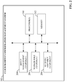
- FIG. 2 is a block diagram of an example cloud manifest configuration management system 202 according to one or more embodiments of this disclosure.
- Aspects of the systems, apparatuses, or processes explained in this disclosure can constitute machine-executable components embodied within machine(s), e.g., embodied in one or more computer-readable mediums (or media) associated with one or more machines. Such components, when executed by one or more machines, e.g., computer(s), computing device(s), automation device(s), virtual machine(s), etc., can cause the machine(s) to perform the operations described.
- Cloud manifest configuration management system 202 can include a queue management component 204, a worker role component 206, a manifest assembly component 208, one or more processors 210, and memory 212.
- one or more of the queue management component 204, worker role component 206, manifest assembly component 208, the one or more processors 210, and memory 212 can be electrically and/or communicatively coupled to one another to perform one or more of the functions of the cloud manifest configuration management system 202.
- components 204, 206, and 208 can comprise software instructions stored on memory 212 and executed by processor(s) 210.
- Cloud manifest configuration management system 202 may also interact with other hardware and/or software components not depicted in FIG. 2 .
- processor(s) 210 may interact with one or more external user interface devices, such as a keyboard, a mouse, a display monitor, a touchscreen, or other such interface devices.
- Queue management component 204 can be configured to receive compressed data packets from one or more cloud agents residing at an industrial facility and organize the industrial data contained in the packets into priority queues that respectively define how the data packets are to be processed by cloud processing services.
- the worker role component 206 can be configured to determine how the data in the respective queues is to be processed based on manifests stored in a customer-specific manifest assembly.
- Manifest assembly component 208 can be configured to create, update, and manage manifests within customer-specific manifest assemblies on the cloud platform.
- the manifests define and implement customer-specific capabilities, applications, and preferences for processing collected data in the cloud, and can be uploaded by a user at the plant facility through a cloud agent.
- the one or more processors 210 can perform one or more of the functions described herein with reference to the systems and/or methods disclosed.
- Memory 212 can be a computer-readable storage medium storing computer-executable instructions and/or information for performing the functions described herein with reference to the systems and/or methods disclosed.
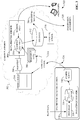
- FIG. 3 is an overview of a system that leverages an agent-based cloud infrastructure to provide data collection and processing services to customer manufacturing sites.
- This system can provide remote collection and monitoring services in connection with alarm and event notification for critical industrial assets, historical data collection, remote system access, system optimization, remote closed-loop control, and other such applications.
- the cloud-based infrastructure enables remote monitoring and reporting of on-premise assets by implementing six general areas of functionality - data ingestion into the cloud, data priority, object modeling, data processing, data analytics, and reporting.
- a data concentrator 328 collects plant data from one or more industrial assets (e.g., data generated by one or more industrial controllers, such as industrial devices 108 or 110) at a plant facility.
- industrial assets can include industrial controllers that monitor and control industrial I/O devices, data servers and historians, motor drives, remote I/O interfaces that remotely interface groups of I/O devices to one or more of the industrial controllers, boilers or other industrial machines, or other such assets.
- data concentrator 328 can monitor one or more controller tags defined in a tag archive and store data in local data storage 336 (e.g., a local structured query language, or SQL, server) associated with a historian 338.
- the collected data can include historical data (e.g., alarm history, status history, trend data, etc.), live data values read from the industrial assets, alarm data generated by the industrial assets, or other types of data.
- An on-premise cloud agent 340 is configured to collect the live or historical data from the industrial assets, either directly or by accessing data storage 336 associated with data concentrator 228.
- Cloud agent 340 can execute on any suitable hardware platform (e.g., a server, a LINUX box, etc.), and acts as a generic gateway that collects data items from the various industrial assets on the plant network and packages the collected data according to a generic, uniform data packaging schema used to move the on-premise data to a cloud platform 302.
- Cloud agent 340 provides a software mechanism to dynamically link on-premise-to-cloud gateways.
- Cloud agent 340 provides an expandable data type schema that allows new data types to be added without the need to redeploy the monitoring system to the cloud.
- the cloud agent 340 can intelligently sort and organize the data based on defined criteria, including but not limited to time of occurrence and/or user-defined priorities.
- Cloud agent 340 can be, for example, a service (e.g., a Windows service) that periodically collects and transmits serialized and compressed data into the cloud domain using standard web services over HTTPS/SSL.
- a service e.g., a Windows service
- FIG. 3 depicts data concentrator 328 as the data source for cloud agent 340. This configuration can be useful if there are a large number of data points to monitor, since the data concentrator can 328 can link multiple industrial devices or other data sources to a single cloud agent 340. However, some embodiments of cloud agent 340 can collect data directly from the industrial assets themselves; e.g., through a common industrial protocol link, or through middleware applications such as OPC clients.
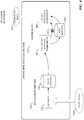
- Cloud agent functionality is illustrated in more detail with reference to FIG. 4 .
- On-premise data collection is enabled by a collection of services that function as a virtual support engineer for processing data.
- Data concentrator 328 and cloud agent 340 respectively implement two main functions associated with data collection - data concentration using a historian 338 and associated data storage 336 (e.g., an SQL server), and cloud data enablement using cloud agent services executed by cloud agent 340.
- plant data 410 is collected by data concentrator 328 at the plant facility.
- plant data 410 may comprise stamping press time series sensor data, made up of thousands of data points updated at a rate of less than a second.
- Collection services component 402 of cloud agent 340 implements collection services that collect device data, either from data concentrator's associated data storage (e.g., via an SQL query) or directly from the devices themselves via a common industrial protocol (CIP) link or other suitable communication protocol. For example, to obtain data from data concentrator 328, collection services component 402 may periodically run a data extraction query (e.g., an SQL query) to extract data from data storage 336 associated with data concentrator 328. Collection services component 402 can then compress the data and store the data in a compressed data file 412.
- a data extraction query e.g., an SQL query
- Queue processing services executed by queue processing component 404 can then read the compressed data file 412 and reference a message queuing database 414, which maintains and manage customer-specific data collection configuration information, as well as information relating to the customer's subscription to the cloud platform and associated cloud services. Based on configuration information in the message queuing database 414, queue processing component 404 packages the compressed data file 412 into a data packet and pushes the data packet to the cloud platform.
- the cloud agent 340 can support injecting data packets as torrential data 416.
- Message queuing database 414 can include site-specific information identifying the data items to be collected (e.g., data tag identifiers), user-defined processing priorities for the data tags, firewall settings that allow cloud agent 340 to communicate with the cloud platform through a plant firewall, and other such configuration information.
- Configuration information in message queuing database 414 instructs cloud agent 340 how to communicate with the identified data tags and with the remote data collection services on the cloud platform.
- cloud agent 340 can also perform local analytics on the data prior to moving the data to the cloud platform. This can comprise substantially any type of pre-processing or data refinement that may facilitate efficient transfer of the data to the cloud, prepare the data for enhanced analysis in the cloud, reduce the amount of cloud storage required to store the data, or other such benefits.
- cloud agent 340 may be configured to compress the collected data using any suitable data compression algorithm prior to migrating the data to the cloud platform. This can include detection and deletion of redundant data bits, truncation of precision bits, or other suitable compression operations.
- cloud agent 340 may be configured to aggregate data by combining related data from multiple sources.
- cloud agent 340 may also encrypt sensitive data prior to upload to the cloud.
- cloud agent 340 may filter the data according to any specified filtering criterion (e.g., filtering criteria defined in a filtering profile stored on the cloud agent). For example, defined filtering criteria may specify that pressure values exceeding a defined setpoint are to be filtered out prior to uploading the pressure values to the cloud.
- cloud agent 340 may also transform a specified subset of the industrial data from a first format to a second format in accordance with a requirement of a cloud-based analysis application.
- a cloud-based reporting application may require measured values in ASCII format.
- cloud agent 340 can convert a selected subset of the gathered data from floating point format to ASCII prior to pushing the data to the cloud platform for storage and processing. Converting the raw data at the industrial device before uploading to the cloud, rather than requiring this transformation to be performed on the cloud, can reduce the amount of processing load on the cloud side.
- Cloud agent 340 may also associate metadata with selected subsets of the data prior to migration to the cloud, thereby contextualizing the data within the industrial environment. For example, cloud agent 340 can tag selected subsets of the data with a time indicator specifying a time at which the data was generated, a quality indicator, a production area indicator specifying a production area within the industrial enterprise from which the data was collected, a machine or process state indicator specifying a state of a machine or process at the time the data was generated, a personnel identifier specifying an employee on duty at the time the data was generated, or other such contextual metadata. In this way, cloud agent 340 can perform layered processing of the collected data to generate meta-level knowledge that can subsequently be leveraged by cloud-based analysis tools to facilitate enhanced analysis of the data in view of a larger plant context.
- cloud agent 340 can support HTTPS/SSL, certificate authority enabled transmission, and/or unique identity using MAC addresses. Cloud agent 340 can also support store-and-forward capability to ensure data is not lost if the agent becomes disconnected from the cloud.
- cloud agent 340 sends compressed data packet 324 to the cloud-based data collection and monitoring system on cloud platform 302 via a cloud storage fabric 316.
- the data packet 324 conveys parameters and data (compressed and serialized) used by the cloud-side services to reconstruct the domain data structure in the cloud using auxiliary tenant-level manifests.
- the cloud services direct remote storage of the received data into preconditioned transient blobs 310.
- the cloud platform 302 can use agent reasoning and collective bargain features to determine a data storage locale.
- users at the plant facility can dynamically configure one or more priority queues 304 that respectively define how the data packets are processed in the cloud platform 302. For example, separate queues may be defined for alarms, live data, and historical data, allowing data to be organized according to these data types.
- the historical data queue can relate to time-series records, which can be accessed through an application programming interface (API) (e.g., an SQL API or other suitable API).
- API application programming interface
- the alarms queue can relate to abnormal situations, where the alarm data can also be accessed through the API.
- This alarms queue can comprise multiple queues associated with different alarm priorities, to allow for individual processing for different alarms having different levels of criticality.
- servers, controllers, switches, etc. can be monitored using a number of protocols, and at a certain point (e.g., at the end of a monitoring cycle) alarms can be queued and cloud agent 340 can send the alarms to the cloud.
- Alarms can be reactive (e.g., alarms that trigger when a motor fails, when a CPU crashes, when an interlock is tripped, etc.) or proactive (e.g., a monitoring system may track consumables on a machine and generate an alarm when time to reorder, monitor cycle counts on a machine and generate an alarm when to schedule preventative maintenance, generate an alarm when temperatures fall outside defined bandwidths, send a notification when a computer's memory is 80% full, etc.).
- the live data queue can relate to substantially real-time monitored data, such as current temperatures, current pressures, etc.
- the live data values can also be accessed through the API (e.g., a SQL API).
- the queues described above are not intended to be limiting, and it is to be appreciated that other types of priority queues can be defined according to the needs of the end user. For example, queues may be defined for specific devices or device types (e.g., motor drives) for uploading of device parameter and/or performance data.
- cloud agent 340 can allow the user to define these priority queues 304 from the on-site location and to define how data in each queue is handled. For example, the user can define, for each queue, an upload frequency, a priority level (e.g., which data queues should take processing priority over other data queues), identities of cloud partitions or databases in which data from the respective queues should be stored, and other such information.
- the live data queue may be defined to process live data values that are to be used by a remote operator interface application to view substantially real-time data from the plant facility, while historical data queue may be used to process historian data for archival storage in a historical database on cloud storage. Accordingly, the live data queue may be assigned a higher priority relative to the historical data queue, since data in the live data queue is more time-critical than data in the historical queue.
- users can assign priorities to respective data tags or tag groups at the customer site. These priority assignments can be stored in the message queuing database 414 of the cloud agent 340. Accordingly, when queue processing component 404 packages the collected data to be moved to the cloud platform, the collected data items can be packaged into data packets according to priority (as defined in message queuing database 414), and the respective data packet headers populated with the appropriate priority level. If access to the cloud is unavailable, data will continue to be collected by collection services component 402 and stored locally on the cloud agent in local storage associated with collections services. When communication to the cloud is restored, the stored data will be forwarded to cloud storage. Queue processing services can also encrypt and send storage account keys to the cloud platform for user verification.
- Message queuing services implemented by queue processing component 404 of cloud agent 340 encapsulates or packages the compressed data file by adding customer-specific header information to yield a compressed data packed (e.g., compressed data packet 324 of FIG. 3 ).
- the queue processing component 404 can access a message queuing database (e.g., message queuing database 414 of FIG. 4 ), which stores customer site configuration information and manages the customer's subscription to the cloud platform services.
- the message queuing database may include such information as a customer identifier associated with the customer entity associated with the industrial enterprise, a site identifier associated with a particular plant facility from which the data was collected, a priority to be assigned to the data (which may be dependent on the type of information being sent; e.g., alarm data, historical data, live operational data, etc.), information required to facilitate connection to the customer's particular cloud fabric, or other such information.
- the information included in the header is based on this customer-specific information maintained in the message queuing database.
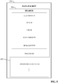
- An example compressed data packet is illustrated in FIG. 5 . As shown, the cloud agent's message queuing services add a header 504 to compressed data file 412 to yield the compressed data packet 324.
- header 504 contains customer-specific data read from message queuing database 414.
- header 504 can include a unique customer identifier, a site identifier representing a particular plant facility, a virtual support engineer identifier, a data priority for the data in the compressed data file 412, a message type, and a process identifier that specifies a particular manifest application on the cloud platform that should be used to process the data on the cloud side.
- Packaging the data in this way can allow data from diverse data sources to be packaged together using a uniform, generic data packaging schema so that the data can be moved to the cloud infrastructure
- cloud agent 340 When cloud agent 340 sends a data packet to the cloud-based remote processing service, the service reads the packet's header information to determine a priority assigned to the data (e.g., as defined in a data priority field of the data packet) and sends the data packet (or the compressed data therein) to a selected one of the user defined priority queues 304 based on the priority.
- a data process service 308 processes data in the respective priority queues 304 according to the predefined processing definitions.
- the data processing service includes a worker role 332 that determines how the queued data is to be processed based on manifests (e.g., system manifests, tag manifests, and metric manifests) stored in a customer-specific manifest assembly 334.
- manifests e.g., system manifests, tag manifests, and metric manifests
- the user can interact with cloud agent 340 to configure a new manifest for the new queue, the manifest defining such aspects as processing priority for the data, upload frequency for the data, where the data is to be routed or stored within cloud storage, and other such information.
- Cloud agent 340 can then upload the new manifest 306 together with the data (or independently of the data).
- the new manifest 306 is then added to the customer's manifest assembly 334 with the other manifests defined for the customer, so that worker role 332 can leverage the new manifest 306 to determine how data in the new queue is to be processed.
- This new manifest 306 need only be uploaded to the cloud-based remote monitoring service once.
- the manifest may define where the data is to be stored within cloud storage (e.g., in a historical database, and Alarms and Live Data database, big data storage 312, etc.), and whether processing of the new data queue is to take priority over other data queues.
- the manifest assembly 334 may only accept a new manifest if the manifest is accompanied by a unique key associated with the client.
- reporting services 314 can deliver data in cloud storage (e.g., from the big data storage 312) to the client devices 322 in a defined format.
- reporting services 314 can leverage collected data stored in the cloud repository to provide remote operator interfaces to client devices 322 over the Internet.
- An analytic engine 318 executing on the cloud platform 302 can also perform various types of analysis on the data stored in big data storage 312 and provide results to client devices 322.
- FIG. 6 is a block diagram illustrating an example agent architecture for collection of data from on-premise industrial devices according to one or more embodiments.
- data is collected from a number of devices and applications 602 at the customer site, including an alarm database 602a, data historian 602b, motor drives 602c and 602d, live data server 602e, and a customer database 602f.
- these data sources comprise a diverse, heterogeneous collection of devices and applications, collection and pre-processing of data from these sources can be carried out by generic services 604 (e.g., service libraries).
- Generic services 604 can include utilities for identifying the data locations (e.g., devices, applications, tags, registers, etc.) from which data is to be retrieved, utilities for compressing or otherwise pre-processing the data, and providing the data to the message queuing layers 606 of the cloud agents.
- the workload services 608 of the cloud agents can also utilize generic services 610 to encapsulate and send the data to the cloud fabric.
- the message queuing layers 606 and workload services 608 make up the backbone of the decoupled agent architecture.
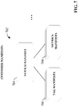
- FIG. 7 is a conceptual diagram of an example manifest assembly 702.
- a system manifest 704 resides in the manifest assembly 334.
- System manifest 704 can correspond to a particular data collection device (e.g., an on-premise data collector including a cloud agent), and can include links to customer-specific and application-specific tag manifests 706 and metrics manifests 708 that define actions that can be performed on the data received from that data source.
- a compressed data packet e.g., compressed data packet 324 of FIG. 5
- data process service 308 uses information packaged in the header 504 of the packet to identify the appropriate manifest assembly (system manifest 704, tag manifest 706, and metrics manifest 708) for processing the data contained in the compressed data file 412.
- a worker role e.g., worker role 332 of FIG.3 ) fetches and loads the identified manifest assembly, which is then executed on the received data.
- the metrics manifest 708 identifies one or more generic procedures that can be retrieved and executed on the data, as well as application-specific ranges, coefficients, and thresholds that may be passed to the retrieved procedures as parameters.
- the tag manifest 706 identifies tag names used to map the data items in the compressed data file to variables or tags defined in the retrieved generic procedures.
- FIG. 8 illustrates an example hierarchical architecture 800 for the manifest assembly according to one or more embodiments.
- An example system manifest 816 maintained on the cloud platform in a manifest repository can be organized into multiple hierarchical levels.
- Each individual customer entity that will access the manifest repository for processing of on-premise data can be defined under a customer identifier level 804. Since each customer entity may operate multiple plant facilities or sites, one or more site identifier nodes are defined for each customer identifier node on a site identifier level 806.
- site identifier nodes are defined for each customer identifier node on a site identifier level 806.
- VSE virtual support engineer
- a message type level 812 and a process identifier level 814 are defined under the VSE identifier level 808.
- hierarchical levels of the example manifest depicted in FIG. 8 correspond to data fields included in header 504 of compressed data packet 324 (see FIG. 5 ).
- data process service 308 on the cloud platform leverages the information contained in the header to navigate the manifest's hierarchical architecture 800 to identify the manifest assembly (system manifest, metrics manifest, and tag manifest) to be executed on the data contained in compressed data file 412.
- FIG. 9 a block diagram of an example customer hierarchy 900 is illustrated.
- a customer 902 operates three geographically diverse facilities or sites 904.
- a number of on-premise data collectors 906 e.g., devices executing cloud agents that collect data from one or more data sources, as illustrated in FIGs. 3 and 4 ) are deployed at the various customer sites 904 and collect data from one or more industrial devices 908 or other data sources at the plant facility.
- Customer hierarchy 900 is used by the cloud architecture to model and organize customer site information.
- cloud agents associated with the on-premise data collectors 906 compress data collected from the industrial devices 908 to yield a compressed data file, and package the compressed data file with header information, as illustrated in FIG. 5 .
- the customer ID, site ID, and VSE ID fields of header 504 correspond to the customer, site, and on-premise data collector levels, respectively, of customer hierarchy 900.
- the worker role 332 executing on the cloud platform identifies and invokes a particular system manifest within a manifest repository based on the customer ID, site ID, and VSE ID values in the header.
- the worker role 332 determines the particular metrics manifest and tag manifest associated with the system-level manifest to be used to process the data received in the packet.
- the metrics manifest 802 defines one or more metrics or actions (identified by the process identifier field of the compressed data packet header 504) that can be carried out on the data.
- the metrics manifest 802 also defines the coefficients, thresholds, and ranges to be used for each identified metric.
- Each metric (process) corresponds to a generic procedure stored on the cloud platform in association with the manifest assembly 334.
- the metrics manifest 802 defines which of the available generic procedures are to be used to process the data received in the packet.
- Worker role 332 uses the customer identifier, site identifier, and VSE identifier fields of header 504 to navigate the corresponding levels of the system manifest and select a particular tag manifest 810 for processing of the data.
- the tag manifest 810 defines tag names used to map data items in the compressed data file 412 (or in customer data storage) to the one or more metrics (processes) that will operate on the data, as defined by the metrics manifest.
- the tag manifest 810 also identifies which process identifiers have ownership over each tag name. The particular process that will be executed on the data is identified by the message type and process identifier fields of the header 504.
- the system manifest may define multiple message types (e.g., alarms, historical data, live data, etc.), and, for each defined message type, define one or more namespaces corresponding to a given process identifier.
- the namespaces identify corresponding applications stored in association with the manifest assembly that can be loaded by worker role 332 and executed on the data contained in the encapsulated data file.
- These applications may specify a final destination for the data (e.g., big data storage on the cloud, one or more specified client devices, a visualization application, etc.), or may comprise algorithms or computational procedures to be carried out on the data to yield a desired result (e.g., a net power calculation, an efficiency calculation, a power guarantee calculation, etc.).
- the worker role in the cloud platform will load the appropriate manifest assembly for processing a received data packet based on the customer from which the data was received, as well as other data attributes - such as the customer facility or site, a device from which the data was received, the type of data (e.g., alarm data, historian data, live data from industrial devices, etc.), a specified process or metric, etc. - identified by the header of the compressed data packet.
- the cloud agent effectively applies a customer-specific model to the data that describes the data's context within the plant hierarchy, as well as the data's relationship to other data items across the enterprise. This information can then be leveraged on the cloud side to appropriately handle and process the data based on the data's role in the larger enterprise as well as user-defined processing and storage preferences.
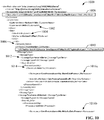
- FIG. 10 illustrates an example system manifest 1000.
- the system manifest 1000 conforms to a hierarchical structure wherein levels of the hierarchy can be navigated based on data provided in the data packet header 504.
- the system manifest can include links to one or more available tag manifests and metrics manifests that can be selectively invoked to process data received from the cloud agents on the plant floor.
- the system manifest includes hierarchical levels for customer ID 1002, site ID 1004, and VSE ID 1006. Multiple customers, sites, and VSEs can be defined within each of the respective levels, and a particular tag manifest and metrics manifest can be associated with a given customer, site, and VSE.
- a particular metrics manifest 1008 and tag manifest 1010 is associated with a customer ID 1002, site ID 1004, and VSE ID 1006. Additional hierarchical levels for message type 1012 and process ID 1014 are used by the worker role to identify the respective namespaces 1016 and associated assembly files that define how the data is to be processed by the cloud-based data process services.
- Alarm data is associated with the namespace CoreProcessAssembly.AlarmDataProcess (assembly file name CoreProcessAssembly.dll), while Historical data is associated with the namespace CoreProcessAssembly.HistoricalDataProcess.
- FIG. 11 illustrates an example tag manifest 1100, which identifies the data to be operated on by the identified metrics.
- the data is identified using tag names 1102 that specify the data to be extracted from one or both of the compressed data packet or cloud-based customer storage.
- the tag manifest 1100 also defines one or more application IDs 1108 representing applications that can be invoked and executed on the data.
- the application IDs 1108 are respectively defined in terms of one or more process IDs 1104 corresponding to stored generic procedures that will be executed on the data when the corresponding application ID is invoked.
- FIG. 11 illustrates an example tag manifest 1100, which identifies the data to be operated on by the identified metrics.
- the data is identified using tag names 1102 that specify the data to be extracted from one or both of the compressed data packet or cloud-based customer storage.
- the tag manifest 1100 also defines one or more application IDs 1108 representing applications that can be invoked and executed on the data.
- the application IDs 1108 are respectively defined in terms of one or more process IDs 1104 corresponding to
- application ID 1.1 (named “TurboExpander1”) comprises three processes - process ID 1 ("NetPower”), process ID 2 (“CycleEfficiency”), and process ID 3 (“PowerGuarantee”). These processes - which correspond to universal, generic procedure code stored on the cloud platform - will be applied to the data corresponding to the tag names 1102 when the TurboExpander1 application is invoked.
- Controller IDs 1106 representing controllers from which some or all of the data was retrieved are also defined in the tag manifest 1100.
- each tag name definition also specifies which of the process IDs 1104 and controller ID 1106 own the data corresponding to the tag.
- FIG. 12 illustrates an example metrics manifest 1200, which defines the coefficients, thresholds, and ranges to be used for each of the processes (metrics) specified in by the process IDs 1104 in the tag manifest 1100.
- a metric ID 1202 (corresponding to the process IDs defined in the tag manifest 1100)
- a set of coefficients 1204 and thresholds 1206 are defined.
- the metrics manifest 1200 defines a coefficient name, a unit, and a value.
- the metrics manifest 1200 defines a value and a unit.
- each metric (process) defined in the manifest assembly corresponds to a generic procedure stored in generic procedure storage on the cloud platform.
- FIG. 13 is a block diagram illustrating retrieval and application of generic procedures by the cloud-based data process services based on customer-specific and application-specific manifest assemblies.
- System manifest 1304 has links to application-specific tag manifests 1306 and metrics manifests 1308.
- the header information in the compressed data packet informs the worker role which particular tag manifest 1314 and metrics manifest 1310 are to be invoked to process the data contained in the compressed data file of the packet.
- the tag manifest 1314 identifies the tag names corresponding to the data items to be extracted from customer-specific cloud storage 1318 for processing, where the data maintained in cloud storage 1318 is provided by the compressed data packets received by the on-premise cloud agents.
- the metrics manifest 1310 identifies the ranges, coefficients, and thresholds that are to be used as parameters for execution of the procedures on the identified data tags.
- the selected metrics manifest 1310 and tag manifest 1314 are associated with the Turbo_Expander_1 namespace 1312, which is selected by the worker role based on one or more fields in the data packet header 504.
- the customer ID, site ID, and VSE ID fields of the header may be used to identify the system manifest 1304 and the associated metrics manifest 1310 and tag manifest 1314 1304 to be invoked.
- the particular application defined by the tag manifest 1314 to be applied to the data may be specified by the message type and process ID fields of the header 504.
- the Turbo_Expander_1 namespace 1312 (corresponding to the TurboExpander1 application ID define in the tag manifest 1100) comprises three processes - NetPower, CycleEfficiency, and PowerGuarantee. These processes correspond to generic procedures maintained in generic procedure storage 1302.
- Generic procedure storage 1302 stores universal, generic procedures or code that can be fetched by the worker role as needed based on the particular process specified by the identified manifest assembly.
- the worker role examines tag manifest 1314 to determine the processes corresponding to the Turbo_expander_1 namespace 1312, and retrieves the corresponding generic procedures from generic procedure storage 1302.
- the tag manifest 1314 also defines the tag names corresponding to the customer data stored in customer-specific cloud storage 1318 to which the retrieved procedures are to be applied. Accordingly, this data is extracted from cloud storage 1318.
- the retrieved procedures are then executed on the retrieved customer data, using the ranges, coefficients, and thresholds defined by the metrics manifest 1310 as operational parameters.
- any type of procedure can be defined in generic procedure storage 1302 and applied to the data tags.
- the net power, cycle efficiency, and power guarantee procedures can be configured to derive calculated values (e.g., net power values, efficiency values, etc.) by applying algorithms to the data corresponding to the identified data tags.
- Other types of procedures may instruct that the data be sent to a particular destination (e.g., a client device, a permanent cloud storage location, big data storage, etc.), or that the data be sent to a different remote cloud platform.
- Other types of generic operations e.g., interpolation
- the generic procedures in generic procedure storage 1302 yield a prebuilt library of generic functions that can reused across tenants.
- FIGs. 14-16 are flowcharts illustrating three different example implementations for performing data processing in the cloud platform in accordance with a given manifest assembly.
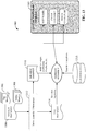
- FIG. 14 is a flowchart illustrating the use of a manifest assembly to execute near real-time stream processing in the cloud platform.
- worker role 332 fetches an assembly object 1402 corresponding to the manifest assembly identified by the data packet's header.
- the data file contained in the compressed data packet is extracted and transformed into one or more transient blobs 310 by the cloud processing services.
- the assembly object 1402 transfers data from the transient blobs 310 to cloud memory 1406.
- the assembly object 1402 extracts the tag list from the tag manifest 1404 identified by the header.
- the data identified by the tag list is then extracted from cloud memory 1406, and stream processing is executed on the extracted data in accordance with the parameters (ranges, thresholds, etc.) defined in the metrics manifest 1408.
- the process depicted in FIG. 14 facilitates near real-time processing of plant floor data as it is received at the cloud platform.
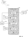
- FIG. 15 is a flowchart illustrating the use of a manifest assembly to execute big data processing in the cloud platform.
- worker role 332 fetches assembly object 1502 in response to receipt of a data packet, and the worker role 332 transfers data from a transient blob to cloud memory.
- the assembly object 1502 reads a tag list from tag manifest 1504, which may identify data items stored in big data storage 312 (see FIG. 3 ).
- the assembly object 1502 then invokes processing of the identified data in big data storage based on parameters read from metrics manifest 1506.
- the processing may comprise parallel processing of the data stored in big data storage as well as data extracted from transient blobs 1508.
- FIG. 16 is a flowchart illustrating the use of a manifest assembly to execute analytics based on structured data.
- worker role 332 fetches an assembly object 1602 corresponding to a manifest assembly identified by a received data packet.
- Data from one or more transient blobs 1604 representing the data file extracted from the data packet is transferred from the blobs to a SQL database 1608 or other type of relational database.
- the assembly object 1602 then extracts a tag list from tag manifest 1606 identifying the tag names on which metrics are to be executed.
- the data identified by the tag names are then extracted from the SQL database 1608, together with time stamp information associated with the data. Metrics are then executed on the extracted data based on parameters defined by the metric manifest 1610.
- the implementation depicted in FIG. 16 facilitates time-series processing of data stored in SQL database 1608.
- embodiments described herein are not limited to the processing types depicted in FIGs. 14-16 .
- the same cloud application can include a combination of different types of processing implementations.
- the same cloud application could support any combination of real-time processing, big data processing, continuous cycle processing, user-triggered processing (e.g., processing triggered by user input entered via a remote dashboard or other type of interface), etc.
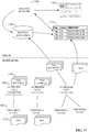
- FIG. 17 illustrates delivery of tag manifest data to the cloud platform according to one or more embodiments.
- on-premise data collectors 906 collect data from industrial devices 908 (e.g., in the form of .dat files).
- the on-premise data collectors 906 also maintain tag manifest data 1702 identifying the data tags available in the respective devices 908.
- the tag manifest data 1702 can also define how the data collected from their associated devices is to be processed.
- the tag manifest data 1702 may also describe hierarchical relationships between the data based at least in part on a hierarchical object model definition.
- the on-premise data collectors 906 send the tag manifest data 1702 to the manifest repository 1706 on the cloud platform.
- Data processing services executing on the cloud platform will only update the portions of the customer's manifest required to implement the change. For example, if the new data tags are to be processed using an existing priority queue, the cloud platform services may only update the portion of the manifest required to add the new data tags to the specified queue. If a new priority queue is defined in the uploaded tag manifest data 1702, the cloud platform services will update the appropriate portions of the customer's manifest to create the new queue and associate the new data tags with the queue.
- the tag manifest data 1702 facilitates generation of a customer-specific object model in the cloud platform, which can be used to simplify data processing at the cloud level, and to facilitate suitable processing and meaningful reporting of the data.
- the tag manifest may define a hierarchical structure of the customer's enterprise from the plant level down to the tag level.
- the tag manifest may include information defining control system identifiers, controller identifiers, network identifiers, application identifiers, functional descriptions of the customer's various industrial assets, tag names, and hierarchical relationships between these various entities.
- An analytics manager 1704 can leverage the manifest data maintained in the manifest repository 1706 to generate trend displays 1708 for the collected data, or to render time-stamped data 1710 organized according to plant, line, workcell, machine, or any other suitable organization criterion.
- FIGs 18-21 illustrate various methodologies in accordance with one or more embodiments of the subject application. While, for purposes of simplicity of explanation, the one or more methodologies shown herein are shown and described as a series of acts, it is to be understood and appreciated that the subject innovation is not limited by the order of acts, as some acts may, in accordance therewith, occur in a different order and/or concurrently with other acts from that shown and described herein. For example, those skilled in the art will understand and appreciate that a methodology could alternatively be represented as a series of interrelated states or events, such as in a state diagram. Moreover, not all illustrated acts may be required to implement a methodology in accordance with the innovation.
- interaction diagram(s) may represent methodologies, or methods, in accordance with the subject disclosure when disparate entities enact disparate portions of the methodologies.
- two or more of the disclosed example methods can be implemented in combination with each other, to accomplish one or more features or advantages described herein.
- FIG. 18 illustrates an example methodology 1800 for creating priority queues and associated manifest assemblies in a cloud platform for cloud-side processing of industrial data.
- an instruction is received at a cloud platform to create a priority queue for receipt and processing of industrial data.
- the instruction can be received, for example, from a cloud agent residing in an industrial facility, via a configuration dashboard or other type of user interface that allows a system administrator to configure priority queues for processing of respective different types of industrial data, or from other priority queue configuration means.
- the priority queue is created in the cloud platform in accordance with one or more processing properties specified by the instruction.
- the priority queue can be one of multiple priority queues defined for a specific customer entity in the cloud platform, where the priority queues define how data packets received from on-premise data collection systems residing at a customer facility are to be processed by cloud processing services executing in the cloud platform.
- Each priority queue can be associated with a different data type (e.g., live data, historical data, alarm data, etc.) or customer-specific application.
- the instruction may define a data type to be assigned to the priority queue; an upload frequency associated with the priority queue; a priority level of the priority queue relative to other defined queues; an identity of a cloud partition, remote cloud, or database to which data in the queue is to be sent for storage; or other such information.
- the priority queue is associated with a manifest assembly that defines one or more operations to be performed on data assigned to the priority queue.
- the manifest assembly can reside in a manifest repository on the cloud platform, and defines one or more procedures to be executed on industrial data assigned to the queue (e.g., placement of the data in a particular storage location, calculation of one or more metrics based on the data, rendering of a data at a remote device, generation of a remote notification when the data satisfies a criterion, etc.).
- the manifest assembly can also identify ranges and thresholds to be used as parameters for the specified procedures, and data tags for mapping data assigned to the priority queue to corresponding variables of the procedures.
- data packets received from on-premise data collection components at a plant facility can be placed in the priority queue based on a determination of that the data packet corresponds to the data type defined for the priority queue, and the data packet can be processed in accordance with the associated manifest assembly.
- FIG. 19 illustrates an example methodology 1900 for receiving and processing industrial data in a cloud platform.
- a data packet is received at a cloud platform from a cloud agent residing at an industrial facility.
- the data packet can comprise industrial data collected from one or more industrial devices at the facility and header information.
- the header information can include data fields corresponding one or more of a customer identifier, a site identifier a device or virtual support engineer identifier, a processing priority of the industrial data contained in the packet, a message type of the data, a process identifier of a process to be performed on the data, or other such information.
- the industrial data contained in the data packet is assigned to a customer-specific priority queue in the cloud platform, where the priority queue is selected from multiple available priority queues based on the header information.
- the priority queue may correspond to the particular message type or process identifier specified in the header information. Accordingly, data processing services executing in the cloud platform can read the header information to determine the message type or process identifier, and assign the industrial data contained in the data packet to the appropriate queue based on this information.
- a manifest assembly for processing of the industrial data is identified based on at least one of the header information or processing properties associated with the priority queue. For example, a customer's system manifest may be organized into multiple hierarchical levels that correspond to data fields of the header information (see, e.g., FIG. 8 ), and a particular tag manifest and metrics manifest associated with the system manifest can be identified by navigating the hierarchical structure based on the data field values of the header information.
- the industrial data is processed in accordance with the manifest assembly (e.g., tag manifest and metrics manifest) identified at step 1906 and one or more processing properties of the priority queue (e.g., a processing frequency for the queue, a storage destination defined by the queue, etc.).
- FIG. 20 illustrates an example methodology 2000 for selection of a manifest assembly for processing of received industrial data.
- a data packet is received at a cloud platform from a cloud agent or other on-premise data collection system.
- the data packet can comprise industrial data collected from one or more industrial devices and header information.
- a system manifest to be used for processing of the industrial data is identified based on a customer identifier, a site identifier, and a device identifier (or virtual support engineer identifier) contained in the header information.
- the cloud platform may maintain a manifest repository storing system manifests for multiple customers and/or customer facilities.
- a worker role can read the customer identifier, site identifier, and device identifier contained in the data packet's header and retrieve the appropriate system manifest corresponding to this header information.
- a metrics manifest associated with the system manifest is identified based on the header information.
- the metrics manifest identifies one or more procedures to be performed on the industrial data contained in the data packet, and application-specific ranges, coefficients, and thresholds to be passed to the one or more procedures as parameters to facilitate processing of the data.
- the system manifest may be linked to multiple metrics manifests associated with the customer, and the worker role can select the appropriate metrics manifest based on the header information.
- a tag manifest associated with the system manifest is identified based on the header information.
- the tag manifest can be one of multiple metrics manifests linked to the system manifest, where the particular tag manifest for processing of the data packet is selected based on the data packet's header information.
- the tag manifest defines tag names that map items of the industrial data contained in the packet (and/or customer data stored in cloud-based storage) to variables defined in the one or more selected procedures.
- the industrial data contained in the data packet is processed in accordance with the system manifest, the metrics manifest, and the tag manifest.
- This may include, for example, fetching one or more stored generic procedures identified by the manifest assembly, extracting industrial data items identify by the tag manifest from the data packet and/or cloud storage, and processing the industrial data with the retrieved procedures using the ranges, thresholds, and coefficients defined by the metrics manifest as parameters.
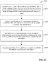
- FIG. 21 illustrates an example methodology 2100 for remotely updating a customer's manifest assembly on a cloud platform.
- tag manifest data is received at a cloud platform from an industrial device.
- the industrial device may be, for example, a new device that has been recently added to a customer's industrial automation system.
- the tag manifest data identifies data tags available in the industrial device and defines a type of processing to be performed on the data tags.
- a portion of the customer's manifest assembly is updated in the cloud platform to add the data tags identified by the tag manifest data to one or more existing tag manifests stored in a manifest repository.
- data packets are received from a cloud agent or other on-premise data collection system.
- the data packets contain industrial data corresponding to the data tags, as well as header information identifying the particular manifest assembly to be used for processing of the industrial data.
- the data packets are processed in accordance with the updated manifest assembly.
- Embodiments, systems, and components described herein, as well as industrial control systems and industrial automation environments in which various aspects set forth in the subject specification can be carried out can include computer or network components such as servers, clients, programmable logic controllers (PLCs), automation controllers, communications modules, mobile computers, wireless components, control components and so forth which are capable of interacting across a network.
- Computers and servers include one or more processors-electronic integrated circuits that perform logic operations employing electric signals-configured to execute instructions stored in media such as random access memory (RAM), read only memory (ROM), a hard drives, as well as removable memory devices, which can include memory sticks, memory cards, flash drives, external hard drives, and so on.
- the term PLC or automation controller as used herein can include functionality that can be shared across multiple components, systems, and/or networks.
- one or more PLCs or automation controllers can communicate and cooperate with various network devices across the network. This can include substantially any type of control, communications module, computer, Input/Output (I/O) device, sensor, actuator, and human machine interface (HMI) that communicate via the network, which includes control, automation, and/or public networks.
- the PLC or automation controller can also communicate to and control various other devices such as standard or safety-rated I/O modules including analog, digital, programmed/intelligent I/O modules, other programmable controllers, communications modules, sensors, actuators, output devices, and the like.
- the network can include public networks such as the internet, intranets, and automation networks such as control and information protocol (CIP) networks including DeviceNet, ControlNet, and Ethernet/IP. Other networks include Ethernet, DH/DH+, Remote I/O, Fieldbus, Modbus, Profibus, CAN, wireless networks, serial protocols, and so forth.
- the network devices can include various possibilities (hardware and/or software components). These include components such as switches with virtual local area network (VLAN) capability, LANs, WANs, proxies, gateways, routers, firewalls, virtual private network (VPN) devices, servers, clients, computers, configuration tools, monitoring tools, and/or other devices.
- VLAN virtual local area network
- WANs wide area network
- proxies gateways
- routers virtual private network
- VPN virtual private network
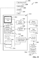
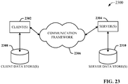
- FIGs. 22 and 23 are intended to provide a brief, general description of a suitable environment in which the various aspects of the disclosed subject matter may be implemented.
- an example environment 2210 for implementing various aspects of the aforementioned subject matter includes a computer 2212.
- the computer 2212 includes a processing unit 2214, a system memory 2216, and a system bus 2218.
- the system bus 2218 couples system components including, but not limited to, the system memory 2216 to the processing unit 2214.
- the processing unit 2214 can be any of various available processors. Multi-core microprocessors and other multiprocessor architectures also can be employed as the processing unit 2214.
- the system bus 2218 can be any of several types of bus structure(s) including the memory bus or memory controller, a peripheral bus or external bus, and/or a local bus using any variety of available bus architectures including, but not limited to, 8-bit bus, Industrial Standard Architecture (ISA), Micro-Channel Architecture (MSA), Extended ISA (EISA), Intelligent Drive Electronics (IDE), VESA Local Bus (VLB), Peripheral Component Interconnect (PCI), Universal Serial Bus (USB), Advanced Graphics Port (AGP), Personal Computer Memory Card International Association bus (PCMCIA), and Small Computer Systems Interface (SCSI).
- ISA Industrial Standard Architecture
- MSA Micro-Channel Architecture
- EISA Extended ISA
- IDE Intelligent Drive Electronics
- VLB VESA Local Bus
- PCI Peripheral Component Interconnect
- USB Universal Serial Bus
- AGP Advanced Graphics Port
- PCMCIA Personal Computer Memory Card International Association bus
- SCSI Small Computer Systems Interface
- the system memory 2216 includes volatile memory 2220 and nonvolatile memory 2222.
- the basic input/output system (BIOS) containing the basic routines to transfer information between elements within the computer 2212, such as during start-up, is stored in nonvolatile memory 2222.
- nonvolatile memory 2222 can include read only memory (ROM), programmable ROM (PROM), electrically programmable ROM (EPROM), electrically erasable PROM (EEPROM), or flash memory.
- Volatile memory 2220 includes random access memory (RAM), which acts as external cache memory.
- RAM is available in many forms such as synchronous RAM (SRAM), dynamic RAM (DRAM), synchronous DRAM (SDRAM), double data rate SDRAM (DDR SDRAM), enhanced SDRAM (ESDRAM), Synchlink DRAM (SLDRAM), and direct Rambus RAM (DRRAM).
- SRAM synchronous RAM
- DRAM dynamic RAM
- SDRAM synchronous DRAM
- DDR SDRAM double data rate SDRAM
- ESDRAM enhanced SDRAM
- SLDRAM Synchlink DRAM
- DRRAM direct Rambus RAM
- Disk storage 2224 includes, but is not limited to, devices like a magnetic disk drive, floppy disk drive, tape drive, Jaz drive, Zip drive, LS-100 drive, flash memory card, or memory stick.
- disk storage 2224 can include storage media separately or in combination with other storage media including, but not limited to, an optical disk drive such as a compact disk ROM device (CD-ROM), CD recordable drive (CD-R Drive), CD rewritable drive (CD-RW Drive) or a digital versatile disk ROM drive (DVD-ROM).
- an optical disk drive such as a compact disk ROM device (CD-ROM), CD recordable drive (CD-R Drive), CD rewritable drive (CD-RW Drive) or a digital versatile disk ROM drive (DVD-ROM).
- a removable or non-removable interface is typically used such as interface 2226.
- FIG. 22 describes software that acts as an intermediary between users and the basic computer resources described in suitable operating environment 2210.
- Such software includes an operating system 2228.
- Operating system 2228 which can be stored on disk storage 2224, acts to control and allocate resources of the computer 2212.
- System applications 2230 take advantage of the management of resources by operating system 2228 through program modules 2232 and program data 2234 stored either in system memory 2216 or on disk storage 2224. It is to be appreciated that one or more embodiments of the subject disclosure can be implemented with various operating systems or combinations of operating systems.
- Input devices 2236 include, but are not limited to, a pointing device such as a mouse, trackball, stylus, touch pad, keyboard, microphone, joystick, game pad, satellite dish, scanner, TV tuner card, digital camera, digital video camera, web camera, and the like. These and other input devices connect to the processing unit 2214 through the system bus 2218 via interface port(s) 2238.
- Interface port(s) 2238 include, for example, a serial port, a parallel port, a game port, and a universal serial bus (USB).
- Output device(s) 2240 use some of the same type of ports as input device(s) 2236.
- a USB port may be used to provide input to computer 2212, and to output information from computer 2212 to an output device 2240.
- Output adapters 2242 are provided to illustrate that there are some output devices 2240 like monitors, speakers, and printers, among other output devices 2240, which require special adapters.
- the output adapters 2242 include, by way of illustration and not limitation, video and sound cards that provide a means of connection between the output device 2240 and the system bus 2218. It should be noted that other devices and/or systems of devices provide both input and output capabilities such as remote computer(s) 2244.
- Computer 2212 can operate in a networked environment using logical connections to one or more remote computers, such as remote computer(s) 2244.
- the remote computer(s) 2244 can be a personal computer, a server, a router, a network PC, a workstation, a microprocessor based appliance, a peer device or other common network node and the like, and typically includes many or all of the elements described relative to computer 2212. For purposes of brevity, only a memory storage device 2246 is illustrated with remote computer(s) 2244.
- Remote computer(s) 2244 is logically connected to computer 2212 through a network interface 2248 and then physically connected via communication connection 2250.
- Network interface 2248 encompasses communication networks such as local-area networks (LAN) and wide-area networks (WAN).
- LAN technologies include Fiber Distributed Data Interface (FDDI), Copper Distributed Data Interface (CDDI), Ethernet/IEEE 802.3, Token Ring/IEEE 802.5 and the like.
- WAN technologies include, but are not limited to, point-to-point links, circuit switching networks like Integrated Services Digital Networks (ISDN) and variations thereon, packet switching networks, and Digital Subscriber Lines (DSL).
- ISDN Integrated Services Digital Networks
- DSL Digital Subscriber Lines
- Communication connection(s) 2250 refers to the hardware/software employed to connect the network interface 2248 to the system bus 2218. While communication connection 2250 is shown for illustrative clarity inside computer 2212, it can also be external to computer 2212.
- the hardware/software necessary for connection to the network interface 2248 includes, for exemplary purposes only, internal and external technologies such as, modems including regular telephone grade modems, cable modems and DSL modems, ISDN adapters, and Ethernet cards.
- FIG. 23 is a schematic block diagram of a sample computing environment 2300 with which the disclosed subject matter can interact.
- the sample computing environment 2300 includes one or more client(s) 2302.
- the client(s) 2302 can be hardware and/or software (e.g., threads, processes, computing devices).
- the sample computing environment 2300 also includes one or more server(s) 2304.
- the server(s) 2304 can also be hardware and/or software (e.g., threads, processes, computing devices).
- the servers 2304 can house threads to perform transformations by employing one or more embodiments as described herein, for example.
- One possible communication between a client 2302 and servers 2304 can be in the form of a data packet adapted to be transmitted between two or more computer processes.
- the sample computing environment 2300 includes a communication framework 2306 that can be employed to facilitate communications between the client(s) 2302 and the server(s) 2304.
- the client(s) 2302 are operably connected to one or more client data store(s) 2308 that can be employed to store information local to the client(s) 2302.
- the server(s) 2304 are operably connected to one or more server data store(s) 2310 that can be employed to store information local to the servers 2304.
- the terms (including a reference to a "means") used to describe such components are intended to correspond, unless otherwise indicated, to any component which performs the specified function of the described component (e.g., a functional equivalent), even though not structurally equivalent to the disclosed structure, which performs the function in the herein illustrated exemplary aspects of the disclosed subject matter.
- the disclosed subject matter includes a system as well as a computer-readable medium having computer-executable instructions for performing the acts and/or events of the various methods of the disclosed subject matter.
- exemplary is used to mean serving as an example, instance, or illustration. Any aspect or design described herein as "exemplary” is not necessarily to be construed as preferred or advantageous over other aspects or designs. Rather, use of the word exemplary is intended to present concepts in a concrete fashion.
- Computer readable media can include but are not limited to magnetic storage devices (e.g., hard disk, floppy disk, magnetic strips...), optical disks [e.g., compact disk (CD), digital versatile disk (DVD)...], smart cards, and flash memory devices (e.g., card, stick, key drive).
- magnetic storage devices e.g., hard disk, floppy disk, magnetic strips
- optical disks e.g., compact disk (CD), digital versatile disk (DVD)...
- smart cards e.g., card, stick, key drive
Landscapes
- Engineering & Computer Science (AREA)
- Physics & Mathematics (AREA)
- General Physics & Mathematics (AREA)
- Software Systems (AREA)
- Theoretical Computer Science (AREA)
- General Engineering & Computer Science (AREA)
- Manufacturing & Machinery (AREA)
- Automation & Control Theory (AREA)
- Quality & Reliability (AREA)
- Signal Processing (AREA)
- Computer Networks & Wireless Communication (AREA)
- Mathematical Physics (AREA)
- Human Computer Interaction (AREA)
- Testing And Monitoring For Control Systems (AREA)
- Management, Administration, Business Operations System, And Electronic Commerce (AREA)
- Debugging And Monitoring (AREA)
Claims (14)
- System (202) zum Verarbeiten industrieller Daten (410, 412) in einer Cloud-Plattform (102, 302), umfassend:einen Speicher (212), der computerausführbare Komponenten speichert;einen Prozessor (210), der operativ mit dem Speicher verbunden ist, der die computerausführbaren Komponenten ausführt, wobei die computerausführbaren Komponenten umfassen:eine Warteschlangenverwaltungskomponente (204), die dazu eingerichtet ist, auf einer Cloud-Plattform, ein Datenpaket (324) von einer Cloud-Agenten-Vorrichtung (340), die sich in einer Industrieanlage (1041, 104N) befindet, zu empfangen (1902) und Industriedaten, die in dem Datenpaket enthalten sind, einer Prioritätswarteschlange (304) in der Cloud-Plattform zuzuweisen (1904);ein Verzeichnis-Zusammenstellungs-Archiv (208, 1706), das dazu eingerichtet ist, einen Satz von Verzeichniszusammenstellungen zu verwalten, die jeweils Operationen definieren, die auf industriellen Daten ausgeführt werden sollen, die auf der Cloud-Plattform empfangen werden; undeine Worker-Rolle-Komponente (206, 332), die eingerichtet ist zum:Identifizieren (1906) einer Verzeichniszusammenstellung (334, 702, 1402, 1502, 1602) aus dem Satz von Verzeichniszusammenstellungen basierend auf einer Header-Information (504), die in dem Datenpaket enthalten ist, undVerarbeiten (1908) der industriellen Daten in der Prioritätswarteschlange gemäß der Verzeichniszusammenstellung,wobei die Verzeichniszusammenstellung ein Systemverzeichnis (704, 816, 1000, 1304) umfasst, wobei das Systemverzeichnis Verknüpfungen zu einem oder mehreren Tag-Verzeichnissen (706, 810, 1100, 1306, 1404, 1504, 1606, 1702) und einem oder mehreren Metrik-Verzeichnissen (708, 802, 1200, 1308, 1408, 1506, 1610) enthält,wobei das eine oder die mehreren Tag-Verzeichnis Tag-Namen definieren, die Datenelementen der industriellen Daten entsprechen, die mittels einer oder mehrerer Prozeduren verarbeitet werden sollen, undwobei das eine oder die mehreren Metrik-Verzeichnisse:die eine oder die mehreren Prozeduren zum Abrufen durch die Worker-Rolle von einem Prozedurspeicher (1302) und zur Ausführung durch die Worker-Rolle auf den industriellen Daten identifizieren, wobei mindestens eine der einen oder mehreren Prozeduren dazu eingerichtet ist, einen oder mehrere errechnete Werte basierend auf den Datenelementen der industriellen Daten abzuleiten, undeinen oder mehrere aus einem Koeffizienten, einem Bereich oder einem Schwellenwert definieren, der als Parameter für die eine oder die mehreren Prozeduren verwendet werden soll.
- System (202) nach Anspruch 1, wobei die Header-Information (504) mindestens eines aus einem Kundenkennungsfeld, einem Standortkennungsfeld, einem virtuellen Unterstützungsingenieur-, VSE, Kennungsfeld, einem Datenprioritätsfeld, einem Nachrichtentypfeld oder einem Prozesskennungsfeld umfasst.
- System (202) nach Anspruch 2, wobei das Systemverzeichnis (704, 816, 1000, 1304) einer Kundenkennung (804), einer Standortkennung (806) und einer VSE-Kennung (808) zugeordnet ist und wobei die Worker-Rolle (206, 332) dazu eingerichtet ist, Verzeichniszusammenstellung basierend auf jeweiligen Werten des Kundenkennungsfelds, des Standortkennungsfelds und des VSE-Kennungsfeld zu identifizieren.
- System (202) nach Anspruch 3, wobei die Worker-Rolle (206, 332) ferner dazu eingerichtet ist, die eine oder mehreren Prozeduren aus einem Cloud-Speicher zum Verarbeiten der industriellen Daten (410, 412) abzurufen basierend auf Informationen in dem Systemverzeichnis.
- System (202) nach Anspruch 4, wobei die Worker-Rolle (206, 332) dazu eingerichtet ist, ein Tag-Verzeichnis des einen oder der mehreren Tag-Verzeichnisse entsprechend der Header-Information (504) des Datenpakets (324) auszuwählen; oder
wobei die Worker-Rolle ferner dazu eingerichtet ist, die den Tag-Namen entsprechenden Datenelemente aus mindestens einem von einem Cloud-Speicher oder dem Datenpaket zu extrahieren und die Datenelemente an die eine oder mehreren Prozeduren zur Verarbeitung weiterzuleiten. - System (202) nach Anspruch 4, wobei die eine oder die mehreren Prozeduren ein Speicherziel für die industriellen Daten (410, 412) definieren oder einen Prozess zum Bestimmen einer Metrik basierend auf den industriellen Daten definieren oder beides, und / oder
wobei das Speicherziel eine rechnerferne Cloud-Plattform ist und die eine oder mehreren Prozeduren bewirken, dass die Worker-Rolle die industriellen Daten von einem Übergangs-Blob-Speicher (310) auf der Cloud-Plattform (102, 302) abruft und die industriellen Daten an einen rechnerfernen Speicherort auf einer anderen Cloud-Plattform sendet. - System (202) nach Anspruch 2, wobei die Verzeichniszusammenstellung (334, 702, 1402, 1502, 1602) und die Header-Information (504) einer gemeinsamen hierarchischen Architektur (800) entsprechen.
- System (202) nach Anspruch 2, wobei die Warteschlangenverwaltungskomponente (204) ferner dazu eingerichtet ist, die Prioritätswarteschlange (304) zum Zuordnen der Industriedaten (410, 412) auszuwählen basierend auf Werten, die in einem oder mehreren von dem Kundenkennungsfeld, dem Standortkennungsfeld, dem VSE-Kennungsfeld, dem Datenprioritätsfeld, dem Nachrichtentypfeld oder dem Prozesskennungsfeld enthalten sind; oder
wobei die Warteschlangenverwaltungskomponente dazu eingerichtet ist, die Prioritätswarteschlange aus einem Satz von Prioritätswarteschlangen auswählt, die jeweiligen unterschiedlichen Verarbeitungsprioritätsstufen zugeordnet sind. - Verfahren (1900) zum Sammeln und Verwalten von Daten in einer Cloud-Plattform (102, 302), umfassend:Empfangen (1902) eines Datenpakets (324) von einer Datensammelvorrichtung, die sich in einer Industrieanlage (1041, 104N) befindet, durch ein System (202) mit mindestens einem Prozessor (210) auf einer Cloud-Plattform, wobei das Datenpaket eine Datei umfasst, die industrielle Daten (410, 412) und einen Header (504) enthält;Zuweisen (1904) der industriellen Daten zu einer Prioritätswarteschlange (304) auf der Cloud-Plattform;Identifizieren (1906) einer Verzeichniszusammenstellung (334, 702, 1402, 1502, 1602) einer Vielzahl von Verzeichniszusammenstellungen, die in einem Verzeichnisarchiv (208, 1706) der Cloud-Plattform gespeichert sind, basierend auf einer aus dem Header gelesenen Information; undVerarbeiten (1908) der industriellen Daten in der Prioritätswarteschlange gemäß der Verzeichniszusammenstellung,wobei die Verzeichniszusammenstellung eine Systemverzeichnis (704, 816, 1000, 1304) umfasst, wobei das Systemverzeichnis Verknüpfungen zu einem oder mehreren Tag-Verzeichnissen (706, 810, 1100, 1306, 1404, 1504, 1606, 1702) und einem oder mehreren Metrik-Verzeichnissen (708, 802, 1200, 1308, 1408, 1506, 1610) enthält,wobei das eine oder die mehreren Tag-Verzeichnisse Tag-Namen definieren, die Datenelementen der industriellen Daten entsprechen, die mittels einer oder mehreren Prozeduren zu verarbeiten werden sollen, undwobei das eine oder die mehreren Metrik-Verzeichnisse:die eine oder die mehreren Prozeduren zum Abrufen durch die Worker-Rolle von einem Prozedurspeicher (1302) und zur Ausführung durch die Worker-Rolle auf den industriellen Daten identifizieren, wobei mindestens eine der einen oder mehreren Prozeduren dazu eingerichtet ist, einen oder mehrere errechnete Werte basierend auf den Datenelementen der industriellen Daten abzuleiten, undeinen oder mehrere aus einem Koeffizienten, einem Bereich oder einem Schwellenwert definieren, der als Parameter für die eine oder die mehreren Prozeduren verwendet werden soll.
- Verfahren (1900) nach Anspruch 9, wobei das Identifizieren (1906) der Verzeichniszusammenstellung (334, 702, 1402, 1502, 1602) umfasst, Identifizieren der Verzeichniszusammenstellung basierend auf Werten von einem oder mehreren Datenfeldern des Headers und wobei die Datenfelder mindestens eines aus einem Kundenkennungsfeld, einem Standortkennungsfeld, einem virtuellen Unterstützungsingenieur-, VSE, Kennungsfeld, einem Datenprioritätsfeld, einem Nachrichtentypfeld oder einem Prozesskennungsfeld umfassen.
- Verfahren (1900) nach einem der Ansprüche 9 bis 10, wobei die Verarbeitung (1908) umfasst:
Abrufen der einen oder mehrerern Prozeduren von einem Prozedurdatenspeicher (1302) der Cloud-Plattform (102, 302). - Verfahren nach einem der Ansprüche 9 bis 11, wobei das Verarbeiten umfasst, Senden der industriellen Daten (410, 412) zu einem durch die Verzeichniszusammenstellung (334, 702, 1402, 1502, 1602) definierten Speicherziel, wobei das Ziel mindestens eines aus einer Define-Cloud-Speicher-Partitionierung, eines Remote-Datenspeichers oder einer Remote-Cloud-Plattform umfasst; oder
wobei die Verarbeitung umfasst, Erzeugen einer Metrik, die sich auf ein industrielles System basierend auf den industriellen Daten bezieht. - Nicht-flüchtiges computerlesbares Medium, auf dem Anweisungen gespeichert sind, die als Antwort auf die Ausführung ein System (202) veranlassen, das einen Prozessor (210) zum Ausführen von Operationen umfasst, wobei die Operationen umfassen:Empfangen, auf einer Cloud-Plattform (102, 302), eines Datenpakets (324) von einer Cloud-Agenten-Vorrichtung (340), die sich auf einer Industrieanlage (1041, 104N) befindet, wobei das Datenpaket eine Datei mit industriellen Daten (410 412) und Header-Information (504) umfasst;Auswählen einer Prioritätswarteschlange (304) einer Vielzahl von Prioritätswarteschlangen auf der Cloud-Plattform basierend auf der Header-Information;Zuweisen der industriellen Daten zu der Prioritätswarteschlange;Auswählen einer Verzeichniszusammenstellung (334, 702, 1402, 1502, 1602) aus einer Vielzahl von Verzeichniszusammenstellungen, die in einem Verzeichnis-Archiv (208, 1706) der Cloud-Plattform gespeichert sind, basierend auf der Header-Information; undVerarbeiten der industriellen Daten in der Prioritätswarteschlange gemäß Verarbeitungsanweisungen, die durch die Verzeichniszusammenstellung spezifiziert sind,wobei die Verzeichniszusammenstellung eine Systemverzeichnis (704, 816, 1000, 1304) umfasst, wobei das Systemverzeichnis Verknüpfungen zu einem oder mehreren Tag-Verzeichnissen (706, 810, 1100, 1306, 1404, 1504, 1606, 1702) und einem oder mehreren Metrik-Verzeichnissen (708, 802, 1200, 1308, 1408, 1506, 1610) enthält,wobei das eine oder die mehreren Tag-Verzeichnisse Tag-Namen definieren, die Datenelementen der industriellen Daten entsprechen, die mittels einer oder mehreren Prozeduren zu verarbeiten werden sollen, undwobei das eine oder die mehreren Metrik-Verzeichnisse:die eine oder die mehreren Prozeduren zum Abrufen durch die Worker-Rolle von einem Prozedurspeicher (1302) und zur Ausführung durch die Worker-Rolle auf den industriellen Daten identifizieren, wobei mindestens eine der einen oder mehreren Prozeduren dazu eingerichtet ist, einen oder mehrere errechnete Werte basierend auf den Datenelementen der industriellen Daten abzuleiten, undeinen oder mehrere aus einem Koeffizienten, einem Bereich oder einem Schwellenwert definieren, der als Parameter für die eine oder die mehreren Prozeduren verwendet werden soll.
- Nicht-flüchtiges computerlesbares Medium nach Anspruch 13, wobei das Auswählen der Verzeichniszusammenstellung umfasst:Auswählen des Systemverzeichnisses (704, 816, 1000, 1304) basierend auf einem oder mehreren einer Kundenkennung (804), einer Standortkennung (806) oder einer virtuellen Unterstützungsingenieurs-, VSE, Kennung (808), die in der Header-Information enthalten sind (504), wobei das Systemverzeichnis eine oder mehrere Prozeduren definiert, die auf die Industriedaten (410, 412) angewendet werden sollen;Navigieren einer hierarchischen Struktur (800) des Systemverzeichnisses basierend auf der Header-Information, um das Tag-Verzeichnis (706, 810, 1100, 1306, 1404, 1504, 1606, 1702) zu identifizieren; undNavigieren der hierarchischen Struktur basierend auf der Header-Information, um das Metrik-Verzeichnis (708, 802, 1200, 1308, 1408, 1506, 1610) zu identifizieren.
Applications Claiming Priority (2)
| Application Number | Priority Date | Filing Date | Title |
|---|---|---|---|
| US201461970798P | 2014-03-26 | 2014-03-26 | |
| US14/525,144 US9843617B2 (en) | 2014-03-26 | 2014-10-27 | Cloud manifest configuration management system |
Publications (3)
| Publication Number | Publication Date |
|---|---|
| EP2924571A2 EP2924571A2 (de) | 2015-09-30 |
| EP2924571A3 EP2924571A3 (de) | 2016-08-10 |
| EP2924571B1 true EP2924571B1 (de) | 2019-01-16 |
Family
ID=52823463
Family Applications (1)
| Application Number | Title | Priority Date | Filing Date |
|---|---|---|---|
| EP15160944.3A Active EP2924571B1 (de) | 2014-03-26 | 2015-03-26 | Cloud-manifest-konfigurationsverwaltungssystem |
Country Status (3)
| Country | Link |
|---|---|
| US (1) | US9843617B2 (de) |
| EP (1) | EP2924571B1 (de) |
| CN (1) | CN104950837B (de) |
Cited By (1)
| Publication number | Priority date | Publication date | Assignee | Title |
|---|---|---|---|---|
| EP3460597A1 (de) * | 2017-09-21 | 2019-03-27 | Siemens Aktiengesellschaft | Erstellen einer konfiguration zur einrichtung einer konfigurationsspezifischen web-basierten applikation und generieren einer solchen konfigurationsspezifischen web-basierten applikation |
Families Citing this family (64)
| Publication number | Priority date | Publication date | Assignee | Title |
|---|---|---|---|---|
| US9647906B2 (en) * | 2012-11-02 | 2017-05-09 | Rockwell Automation Technologies, Inc. | Cloud based drive monitoring solution |
| JP6366247B2 (ja) * | 2013-10-08 | 2018-08-01 | キヤノン株式会社 | 管理サーバシステム、およびその制御方法 |
| US9838476B2 (en) | 2014-03-26 | 2017-12-05 | Rockwell Automation Technologies, Inc. | On-premise data collection and ingestion using industrial cloud agents |
| US9614963B2 (en) | 2014-03-26 | 2017-04-04 | Rockwell Automation Technologies, Inc. | Cloud-based global alarm annunciation system for industrial systems |
| US9900391B2 (en) * | 2014-08-05 | 2018-02-20 | Microsoft Technology Licensing, Llc | Automated orchestration of infrastructure service blocks in hosted services |
| US9577972B1 (en) * | 2014-09-09 | 2017-02-21 | Amazon Technologies, Inc. | Message inspection in a distributed strict queue |
| US10216744B2 (en) * | 2015-05-01 | 2019-02-26 | Microsoft Technology Licensing, Llc | Data migration to a cloud computing system |
| EP3125056B1 (de) * | 2015-07-30 | 2021-04-07 | Siemens Aktiengesellschaft | System und verfahren zur steuerung und/oder analytik eines industriellen prozesses |
| US10375072B2 (en) * | 2015-11-09 | 2019-08-06 | Microsoft Technology Licensing, Llc | Dashboard as remote computing services |
| US10078537B1 (en) * | 2016-06-29 | 2018-09-18 | EMC IP Holding Company LLC | Analytics platform and associated controller for automated deployment of analytics workspaces |
| US10432697B2 (en) * | 2016-07-26 | 2019-10-01 | Salesforce.Com, Inc. | Method and system for re-deploying metadata and associated data from a source organization to a destination organization |
| JP6392817B2 (ja) * | 2016-08-04 | 2018-09-19 | ファナック株式会社 | シミュレーション装置 |
| US10764255B2 (en) | 2016-09-21 | 2020-09-01 | Rockwell Automation Technologies, Inc. | Secure command execution from a cloud monitoring system to a remote cloud agent |
| US10530748B2 (en) | 2016-10-24 | 2020-01-07 | Fisher-Rosemount Systems, Inc. | Publishing data across a data diode for secured process control communications |
| US10619760B2 (en) | 2016-10-24 | 2020-04-14 | Fisher Controls International Llc | Time-series analytics for control valve health assessment |
| US10270745B2 (en) | 2016-10-24 | 2019-04-23 | Fisher-Rosemount Systems, Inc. | Securely transporting data across a data diode for secured process control communications |
| US10257163B2 (en) | 2016-10-24 | 2019-04-09 | Fisher-Rosemount Systems, Inc. | Secured process control communications |
| US10877465B2 (en) | 2016-10-24 | 2020-12-29 | Fisher-Rosemount Systems, Inc. | Process device condition and performance monitoring |
| CN107018170B (zh) * | 2016-10-27 | 2020-09-08 | 阿里巴巴集团控股有限公司 | 一种数据同步方法和设备 |
| CN110036385B (zh) * | 2016-12-02 | 2023-08-08 | 开利公司 | 混合模式云内部部署(on-premise)安全通信 |
| US10528700B2 (en) | 2017-04-17 | 2020-01-07 | Rockwell Automation Technologies, Inc. | Industrial automation information contextualization method and system |
| JP6585656B2 (ja) * | 2017-05-10 | 2019-10-02 | 株式会社ソニー・インタラクティブエンタテインメント | 製造ライン用コンピュータシステム及びそのネットワーク設定方法 |
| US10620612B2 (en) | 2017-06-08 | 2020-04-14 | Rockwell Automation Technologies, Inc. | Predictive maintenance and process supervision using a scalable industrial analytics platform |
| WO2018234741A1 (en) * | 2017-06-23 | 2018-12-27 | Qio Technologies Ltd | Systems and methods for distributed systemic anticipatory industrial asset intelligence |
| US10419437B2 (en) * | 2017-06-30 | 2019-09-17 | Futurewei Technologies, Inc. | Quasi-agentless cloud resource management |
| US11327473B2 (en) * | 2017-07-11 | 2022-05-10 | Rockwell Automation Technologies, Inc. | Dynamically reconfigurable data collection agent for fracking pump asset |
| US10482063B2 (en) * | 2017-08-14 | 2019-11-19 | Rockwell Automation Technologies, Inc. | Modular control manifest generator for cloud automation |
| US10416660B2 (en) | 2017-08-31 | 2019-09-17 | Rockwell Automation Technologies, Inc. | Discrete manufacturing hybrid cloud solution architecture |
| US11095502B2 (en) * | 2017-11-03 | 2021-08-17 | Otis Elevator Company | Adhoc protocol for commissioning connected devices in the field |
| US11200258B2 (en) | 2017-12-20 | 2021-12-14 | Acer Cloud Technology (Us), Inc. | Systems and methods for fast and effective grouping of stream of information into cloud storage files |
| WO2019126265A1 (en) * | 2017-12-22 | 2019-06-27 | Scripps Networks Interactive, Inc. | Cloud hybrid application storage management (chasm) system |
| EP3528186A1 (de) * | 2018-02-19 | 2019-08-21 | Siemens Aktiengesellschaft | Verfahren und system zur bereitstellung von zugriff auf zeitreihendaten in einer cloud-computerumgebung |
| CN108900482B (zh) * | 2018-06-13 | 2021-04-16 | 平安科技(深圳)有限公司 | 脚本的执行方法、服务器管理系统及存储介质 |
| WO2020000362A1 (zh) * | 2018-06-29 | 2020-01-02 | 罗伯特·博世有限公司 | 用于监测和识别电驱动系统中的传感器故障的方法 |
| US11144042B2 (en) | 2018-07-09 | 2021-10-12 | Rockwell Automation Technologies, Inc. | Industrial automation information contextualization method and system |
| JP7458377B2 (ja) * | 2018-08-27 | 2024-03-29 | コンヴィーダ ワイヤレス, エルエルシー | フォグベースのデータ処理を有効にするためのデータサンプルテンプレート(Data Sample Template:DST)管理 |
| TWI673613B (zh) * | 2018-10-17 | 2019-10-01 | 財團法人工業技術研究院 | 伺服器及其資源調控方法 |
| JP7044033B2 (ja) * | 2018-11-06 | 2022-03-30 | 日本電信電話株式会社 | アクセス制御方法、アクセス制御装置、およびデータ処理装置 |
| CN111210045B (zh) * | 2018-11-22 | 2023-07-04 | 中国移动通信集团湖南有限公司 | 一种停机指令发送优化方法 |
| WO2020133250A1 (zh) * | 2018-12-28 | 2020-07-02 | 西门子股份公司 | 数据分析的方法、装置和系统 |
| US11403541B2 (en) | 2019-02-14 | 2022-08-02 | Rockwell Automation Technologies, Inc. | AI extensions and intelligent model validation for an industrial digital twin |
| US11086298B2 (en) * | 2019-04-15 | 2021-08-10 | Rockwell Automation Technologies, Inc. | Smart gateway platform for industrial internet of things |
| CN110191160B (zh) * | 2019-05-10 | 2025-02-07 | 深圳前海微众银行股份有限公司 | 一种并发控制方法和装置 |
| CN110286926B (zh) * | 2019-06-20 | 2021-05-11 | 西北工业大学 | 一种工业机器更新方法及装置 |
| EP3996345B1 (de) * | 2019-08-06 | 2025-09-24 | Siemens Aktiengesellschaft | Verfahren zur konfiguration einer prioritätsebene, cloud-plattform, system, rechenvorrichtung und medium |
| WO2021048818A1 (zh) * | 2019-09-13 | 2021-03-18 | 張奉前 | 工业物联网代理装置 |
| US11435726B2 (en) | 2019-09-30 | 2022-09-06 | Rockwell Automation Technologies, Inc. | Contextualization of industrial data at the device level |
| US11841699B2 (en) | 2019-09-30 | 2023-12-12 | Rockwell Automation Technologies, Inc. | Artificial intelligence channel for industrial automation |
| US11386051B2 (en) * | 2019-11-27 | 2022-07-12 | Sap Se | Automatic intelligent hybrid business intelligence platform service |
| US11249462B2 (en) | 2020-01-06 | 2022-02-15 | Rockwell Automation Technologies, Inc. | Industrial data services platform |
| US11300950B2 (en) * | 2020-02-03 | 2022-04-12 | Rockwell Automation Technologies, Inc. | Systems and methods for automatic configuration of intelligent electronic devices |
| CN111678547A (zh) * | 2020-05-28 | 2020-09-18 | 江苏昊晟塑业科技有限公司 | 一种仪表电信号采集传输的方法 |
| US11726459B2 (en) | 2020-06-18 | 2023-08-15 | Rockwell Automation Technologies, Inc. | Industrial automation control program generation from computer-aided design |
| US11330068B2 (en) | 2020-07-24 | 2022-05-10 | Alibaba Group Holding Limited | Methods and systems for recording user operations on a cloud management platform |
| CN111984830A (zh) * | 2020-07-29 | 2020-11-24 | 中国石油集团工程股份有限公司 | 一种管理运维平台及数据处理方法 |
| US11824650B2 (en) * | 2020-09-10 | 2023-11-21 | Fisher-Rosemount Systems, Inc. | Publish-subscribe communication architecture for highly-versatile field devices in control and automation systems |
| US11956232B2 (en) * | 2021-03-19 | 2024-04-09 | Okta, Inc. | Integration packaging for a multi-tenant computing environment |
| US11853100B2 (en) * | 2021-04-12 | 2023-12-26 | EMC IP Holding Company LLC | Automated delivery of cloud native application updates using one or more user-connection gateways |
| CN114755993B (zh) * | 2022-06-13 | 2022-11-22 | 深圳市玄羽科技有限公司 | 应用于工业互联网的协同控制方法、系统及相关设备 |
| US20240378087A1 (en) * | 2023-05-11 | 2024-11-14 | Google Llc | On-Demand Intercloud Data Storage Transfer |
| US20250004454A1 (en) * | 2023-06-29 | 2025-01-02 | Rockwell Automation Technologies, Inc. | Industrial control program component exploration and playback |
| US12591218B2 (en) | 2023-07-11 | 2026-03-31 | Rockwell Automation Technologies, Inc. | Industrial digital twin model environment |
| US20250119319A1 (en) * | 2023-10-04 | 2025-04-10 | Honeywell International Inc. | Application aware modbus gateway |
| CN120871762B (zh) * | 2025-06-09 | 2026-03-20 | 华电邹县发电有限公司 | 一种发电厂dcs数据采集接口自动化配置方法及系统 |
Family Cites Families (78)
| Publication number | Priority date | Publication date | Assignee | Title |
|---|---|---|---|---|
| US5793843A (en) | 1989-10-31 | 1998-08-11 | Intelligence Technology Corporation | Method and apparatus for transmission of data and voice |
| USRE39989E1 (en) | 1989-10-31 | 2008-01-01 | Morris Walker C | Method and apparatus for transmission of analog and digital |
| US5519605A (en) | 1994-10-24 | 1996-05-21 | Olin Corporation | Model predictive control apparatus and method |
| US7149590B2 (en) | 1996-05-06 | 2006-12-12 | Pavilion Technologies, Inc. | Kiln control and upset recovery using a model predictive control in series with forward chaining |
| US6675226B1 (en) | 1998-11-17 | 2004-01-06 | Rockwell Automation Technologies, Inc. | Network interface for industrial controller providing application programmer interface |
| US6640241B1 (en) | 1999-07-19 | 2003-10-28 | Groove Networks, Inc. | Method and apparatus for activity-based collaboration by a computer system equipped with a communications manager |
| US6850808B2 (en) | 1999-09-24 | 2005-02-01 | Rockwell Software Inc. | Method and system for developing a software program using compound templates |
| US6609034B1 (en) | 2000-03-29 | 2003-08-19 | Epicenter, Incorporated | System and method for remotely controlling and monitoring a plurality of computer systems |
| US7133908B1 (en) | 2000-11-24 | 2006-11-07 | Xerox Corporation | Metrics and status presentation system and method using persistent template-driven web objects |
| US6975913B2 (en) | 2001-07-13 | 2005-12-13 | Siemens Aktiengesellschaft | Database system and method for industrial automation services |
| US6842660B2 (en) | 2001-10-31 | 2005-01-11 | Brooks Automation, Inc. | Device and method for communicating data in a process control system |
| US20030212818A1 (en) * | 2002-05-08 | 2003-11-13 | Johannes Klein | Content based message dispatch |
| US9565275B2 (en) | 2012-02-09 | 2017-02-07 | Rockwell Automation Technologies, Inc. | Transformation of industrial data into useful cloud information |
| US7159209B1 (en) * | 2002-08-19 | 2007-01-02 | Sprint Communications Company L.P. | Inter-application validation tool for use in enterprise architecture modeling |
| US7317969B2 (en) | 2002-09-30 | 2008-01-08 | Ctb Ip, Inc. | Method and system for managing and operating a plurality of farm houses |
| US7339948B2 (en) | 2003-01-22 | 2008-03-04 | Rockwell Automation Technologies, Inc. | Industrial controller providing deterministic communication on ethernet |
| US7149919B2 (en) | 2003-05-15 | 2006-12-12 | Hewlett-Packard Development Company, L.P. | Disaster recovery system with cascaded resynchronization |
| US20050038579A1 (en) | 2003-08-15 | 2005-02-17 | Lewis Michael W. | Interactive maintenance management alarm handling |
| US20050193285A1 (en) * | 2004-02-11 | 2005-09-01 | Eung-Sun Jeon | Method and system for processing fault information in NMS |
| US7676287B2 (en) | 2004-03-03 | 2010-03-09 | Fisher-Rosemount Systems, Inc. | Configuration system and method for abnormal situation prevention in a process plant |
| US7319857B2 (en) | 2004-09-13 | 2008-01-15 | Tekelec | Methods, systems, and computer program products for delivering messaging service messages |
| US7693585B2 (en) | 2004-09-30 | 2010-04-06 | Rockwell Automation Technologies, Inc. | Enabling object oriented capabilities in automation systems |
| US8942834B2 (en) | 2005-06-27 | 2015-01-27 | Rockwell Automation Technologies, Inc. | Method and apparatus for communicating transactions between an industrial controller and a programming interface |
| US20070019641A1 (en) | 2005-07-22 | 2007-01-25 | Rockwell Automation Technologies, Inc. | Execution of industrial automation applications on communication infrastructure devices |
| US20070067458A1 (en) | 2005-09-20 | 2007-03-22 | Rockwell Software, Inc. | Proxy server for integration of industrial automation data over multiple networks |
| US8688780B2 (en) | 2005-09-30 | 2014-04-01 | Rockwell Automation Technologies, Inc. | Peer-to-peer exchange of data resources in a control system |
| CN100399335C (zh) | 2005-11-15 | 2008-07-02 | 李利鹏 | 把源文档转换成目标网页文件的方法 |
| US20080168092A1 (en) | 2007-01-10 | 2008-07-10 | General Electric Company | Systems and methods for turbine control simulation |
| US20090037024A1 (en) | 2007-03-29 | 2009-02-05 | Irobot Corporation | Robot Operator Control Unit Configuration System and Method |
| US8514872B2 (en) | 2007-06-19 | 2013-08-20 | Virtual Hold Technology, Llc | Accessory queue management system and method for interacting with a queuing system |
| US8516521B2 (en) * | 2008-01-14 | 2013-08-20 | Verizon Patent And Licensing Inc. | Interactive learning |
| CN103293953B (zh) | 2008-01-31 | 2017-10-31 | 费希尔-罗斯蒙特系统公司 | 具有用来补偿模型失配的调节的鲁棒的自适应模型预测控制器 |
| US8577655B2 (en) | 2008-06-26 | 2013-11-05 | Siemens Product Lifecycle Management Software Inc. | System and method for constructing virtual NC controllers for machine tool simulation |
| EP2228965A1 (de) | 2009-03-12 | 2010-09-15 | Alcatel Lucent | Gateway und Verfahren zum Anschließen eines IP-Netzwerks an ein Sensornetzwerk |
| US8046444B2 (en) | 2009-03-30 | 2011-10-25 | Rockwell Automation Technologies, Inc. | Universal network adapter for industrial control networks |
| US8204717B2 (en) * | 2009-04-01 | 2012-06-19 | Honeywell International Inc. | Cloud computing as a basis for equipment health monitoring service |
| US7970830B2 (en) | 2009-04-01 | 2011-06-28 | Honeywell International Inc. | Cloud computing for an industrial automation and manufacturing system |
| US9412137B2 (en) | 2009-04-01 | 2016-08-09 | Honeywell International Inc. | Cloud computing for a manufacturing execution system |
| US10033779B2 (en) | 2009-07-08 | 2018-07-24 | Dejero Labs Inc. | Multipath data streaming over multiple wireless networks |
| US8433450B2 (en) | 2009-09-11 | 2013-04-30 | Emerson Process Management Power & Water Solutions, Inc. | Optimized control of power plants having air cooled condensers |
| US8761008B2 (en) | 2009-10-29 | 2014-06-24 | The Boeing Company | System, apparatus, and method for communication in a tactical network |
| US20110134930A1 (en) | 2009-12-09 | 2011-06-09 | Mclaren Moray | Packet-based networking system |
| US8819701B2 (en) | 2009-12-12 | 2014-08-26 | Microsoft Corporation | Cloud computing monitoring and management system |
| NZ607113A (en) | 2010-07-08 | 2014-08-29 | Greenbutton Ltd | A method for estimating job run time |
| EP2418554A1 (de) | 2010-08-02 | 2012-02-15 | ABB Research Ltd. | Verfahren und Computerprogrammprodukte zur Ermöglichung der Überwachung und Steuerung eines technischen Systems |
| US9338238B2 (en) | 2010-12-03 | 2016-05-10 | Siemens Industry, Inc. | Operation scheduler for a building automation system |
| US9176742B2 (en) | 2010-12-27 | 2015-11-03 | Microsoft Technology Licensing, Llc | Converting desktop applications to web applications |
| US8756041B2 (en) | 2011-03-07 | 2014-06-17 | Rockwell Automation Technologies, Inc. | Industrial simulation using redirected I/O module configurations |
| JP5754704B2 (ja) | 2011-04-19 | 2015-07-29 | インターナショナル・ビジネス・マシーンズ・コーポレーションInternational Business Machines Corporation | 複数の産業制御システム間の通信を制御するシステム |
| US8798775B2 (en) | 2011-06-28 | 2014-08-05 | Rockwell Automation Technologies, Inc. | Binding graphic elements to controller data |
| US9781205B2 (en) | 2011-09-12 | 2017-10-03 | Microsoft Technology Licensing, Llc | Coordination engine for cloud selection |
| JP5899749B2 (ja) | 2011-09-27 | 2016-04-06 | 株式会社リコー | 制御システム、制御装置、及び制御プログラム |
| US9163828B2 (en) | 2011-10-31 | 2015-10-20 | Emerson Process Management Power & Water Solutions, Inc. | Model-based load demand control |
| US9143563B2 (en) | 2011-11-11 | 2015-09-22 | Rockwell Automation Technologies, Inc. | Integrated and scalable architecture for accessing and delivering data |
| US9953280B2 (en) | 2011-11-15 | 2018-04-24 | Rockwell Automation Technologies, Inc. | Industry-specific workflows in a manufacturing execution system with premier integration |
| US20130124253A1 (en) | 2011-11-15 | 2013-05-16 | Rockwell Automation Technologies, Inc. | Industry-specific workflows in a manufacturing execution system |
| US20130225151A1 (en) | 2011-12-23 | 2013-08-29 | Microsoft Corporation | Mobile device parental control |
| US9384339B2 (en) | 2012-01-13 | 2016-07-05 | Telecommunication Systems, Inc. | Authenticating cloud computing enabling secure services |
| US9529348B2 (en) | 2012-01-24 | 2016-12-27 | Emerson Process Management Power & Water Solutions, Inc. | Method and apparatus for deploying industrial plant simulators using cloud computing technologies |
| US9477936B2 (en) | 2012-02-09 | 2016-10-25 | Rockwell Automation Technologies, Inc. | Cloud-based operator interface for industrial automation |
| US9189210B2 (en) | 2012-02-29 | 2015-11-17 | Avaya Inc. | Using source code generated from a data model file to generate a graphical user interface from objects in a database |
| US9195511B2 (en) | 2012-03-05 | 2015-11-24 | Accenture Global Services Limited | Differentiated service-based graceful degradation layer |
| US8948465B2 (en) * | 2012-04-09 | 2015-02-03 | Accenture Global Services Limited | Biometric matching technology |
| US9317623B2 (en) * | 2012-04-20 | 2016-04-19 | Yahoo! Inc. | Dynamic webpage image |
| US20130290952A1 (en) * | 2012-04-25 | 2013-10-31 | Jerry W. Childers, JR. | Copying Virtual Machine Templates To Cloud Regions |
| EP2660667B1 (de) | 2012-05-04 | 2021-11-10 | Rockwell Automation Technologies, Inc. | Cloud-Gateway für industrielle Automatisierungsinformationen und Steuersysteme |
| US9629118B2 (en) | 2012-05-10 | 2017-04-18 | Digimarc Corporation | Location based router |
| US9253054B2 (en) | 2012-08-09 | 2016-02-02 | Rockwell Automation Technologies, Inc. | Remote industrial monitoring and analytics using a cloud infrastructure |
| US9467500B2 (en) | 2012-08-09 | 2016-10-11 | Rockwell Automation Technologies, Inc. | Remote industrial monitoring using a cloud infrastructure |
| US20140156234A1 (en) | 2012-12-03 | 2014-06-05 | Rockwell Automation Technologies, Inc., | Input output cloning for industrial automation |
| US9665088B2 (en) | 2014-01-31 | 2017-05-30 | Fisher-Rosemount Systems, Inc. | Managing big data in process control systems |
| US9395708B2 (en) | 2013-03-11 | 2016-07-19 | Johnson Controls Technology Company | Systems and methods for adaptive sampling rate adjustment |
| US20140269531A1 (en) | 2013-03-14 | 2014-09-18 | Aliphcom | Intelligent connection management in wireless devices |
| US20140274005A1 (en) | 2013-03-13 | 2014-09-18 | Aliphcom | Intelligent connection management in wireless devices |
| US20140280796A1 (en) | 2013-03-14 | 2014-09-18 | Joyent, Inc. | Systems and methods for providing a distributed service configuration framework |
| US10133243B2 (en) | 2013-03-15 | 2018-11-20 | Fisher-Rosemount Systems, Inc. | Method and apparatus for seamless state transfer between user interface devices in a mobile control room |
| CN203466840U (zh) | 2013-04-16 | 2014-03-05 | 北京天云融创科技有限公司 | 云服务监控系统 |
| CN103701953B (zh) | 2013-12-31 | 2017-05-24 | 北京智谷睿拓技术服务有限公司 | 传输方法及传输装置 |
-
2014
- 2014-10-27 US US14/525,144 patent/US9843617B2/en active Active
-
2015
- 2015-03-26 EP EP15160944.3A patent/EP2924571B1/de active Active
- 2015-03-26 CN CN201510136419.4A patent/CN104950837B/zh active Active
Non-Patent Citations (1)
| Title |
|---|
| None * |
Cited By (1)
| Publication number | Priority date | Publication date | Assignee | Title |
|---|---|---|---|---|
| EP3460597A1 (de) * | 2017-09-21 | 2019-03-27 | Siemens Aktiengesellschaft | Erstellen einer konfiguration zur einrichtung einer konfigurationsspezifischen web-basierten applikation und generieren einer solchen konfigurationsspezifischen web-basierten applikation |
Also Published As
| Publication number | Publication date |
|---|---|
| CN104950837A (zh) | 2015-09-30 |
| CN104950837B (zh) | 2018-03-13 |
| EP2924571A3 (de) | 2016-08-10 |
| US9843617B2 (en) | 2017-12-12 |
| US20150281319A1 (en) | 2015-10-01 |
| EP2924571A2 (de) | 2015-09-30 |
Similar Documents
| Publication | Publication Date | Title |
|---|---|---|
| EP2924571B1 (de) | Cloud-manifest-konfigurationsverwaltungssystem | |
| US10334048B2 (en) | On-premise data collection and ingestion using industrial cloud agents | |
| US10740293B2 (en) | Modular control manifest generator for cloud automation | |
| US9866635B2 (en) | Unified data ingestion adapter for migration of industrial data to a cloud platform | |
| EP2924572B1 (de) | Analyse auf cloud-ebene für kesselnetze | |
| US10764255B2 (en) | Secure command execution from a cloud monitoring system to a remote cloud agent | |
| US9825949B2 (en) | Device authentication to facilitate secure cloud management of industrial data | |
| EP2704401B1 (de) | Industrielle fernüberwachung durch verwenden einer cloud-infrastruktur | |
| EP3037901B1 (de) | Cloud-basierte emulation und modellierung für automatisierungssysteme | |
| US10416660B2 (en) | Discrete manufacturing hybrid cloud solution architecture | |
| US10135705B2 (en) | Industrial internet of things data pipeline for a data lake | |
| US9253054B2 (en) | Remote industrial monitoring and analytics using a cloud infrastructure |
Legal Events
| Date | Code | Title | Description |
|---|---|---|---|
| PUAI | Public reference made under article 153(3) epc to a published international application that has entered the european phase |
Free format text: ORIGINAL CODE: 0009012 |
|
| AK | Designated contracting states |
Kind code of ref document: A2 Designated state(s): AL AT BE BG CH CY CZ DE DK EE ES FI FR GB GR HR HU IE IS IT LI LT LU LV MC MK MT NL NO PL PT RO RS SE SI SK SM TR |
|
| AX | Request for extension of the european patent |
Extension state: BA ME |
|
| PUAL | Search report despatched |
Free format text: ORIGINAL CODE: 0009013 |
|
| AK | Designated contracting states |
Kind code of ref document: A3 Designated state(s): AL AT BE BG CH CY CZ DE DK EE ES FI FR GB GR HR HU IE IS IT LI LT LU LV MC MK MT NL NO PL PT RO RS SE SI SK SM TR |
|
| AX | Request for extension of the european patent |
Extension state: BA ME |
|
| RIC1 | Information provided on ipc code assigned before grant |
Ipc: H04L 29/08 20060101ALI20160704BHEP Ipc: G06F 9/50 20060101AFI20160704BHEP Ipc: G06F 9/54 20060101ALI20160704BHEP Ipc: H04L 12/863 20130101ALI20160704BHEP |
|
| STAA | Information on the status of an ep patent application or granted ep patent |
Free format text: STATUS: REQUEST FOR EXAMINATION WAS MADE |
|
| 17P | Request for examination filed |
Effective date: 20170202 |
|
| RBV | Designated contracting states (corrected) |
Designated state(s): AL AT BE BG CH CY CZ DE DK EE ES FI FR GB GR HR HU IE IS IT LI LT LU LV MC MK MT NL NO PL PT RO RS SE SI SK SM TR |
|
| STAA | Information on the status of an ep patent application or granted ep patent |
Free format text: STATUS: EXAMINATION IS IN PROGRESS |
|
| 17Q | First examination report despatched |
Effective date: 20180215 |
|
| GRAP | Despatch of communication of intention to grant a patent |
Free format text: ORIGINAL CODE: EPIDOSNIGR1 |
|
| STAA | Information on the status of an ep patent application or granted ep patent |
Free format text: STATUS: GRANT OF PATENT IS INTENDED |
|
| INTG | Intention to grant announced |
Effective date: 20180912 |
|
| GRAS | Grant fee paid |
Free format text: ORIGINAL CODE: EPIDOSNIGR3 |
|
| GRAA | (expected) grant |
Free format text: ORIGINAL CODE: 0009210 |
|
| STAA | Information on the status of an ep patent application or granted ep patent |
Free format text: STATUS: THE PATENT HAS BEEN GRANTED |
|
| AK | Designated contracting states |
Kind code of ref document: B1 Designated state(s): AL AT BE BG CH CY CZ DE DK EE ES FI FR GB GR HR HU IE IS IT LI LT LU LV MC MK MT NL NO PL PT RO RS SE SI SK SM TR |
|
| REG | Reference to a national code |
Ref country code: GB Ref legal event code: FG4D |
|
| REG | Reference to a national code |
Ref country code: CH Ref legal event code: EP |
|
| REG | Reference to a national code |
Ref country code: IE Ref legal event code: FG4D |
|
| REG | Reference to a national code |
Ref country code: AT Ref legal event code: REF Ref document number: 1090213 Country of ref document: AT Kind code of ref document: T Effective date: 20190215 |
|
| REG | Reference to a national code |
Ref country code: DE Ref legal event code: R096 Ref document number: 602015023475 Country of ref document: DE |
|
| REG | Reference to a national code |
Ref country code: NL Ref legal event code: MP Effective date: 20190116 |
|
| REG | Reference to a national code |
Ref country code: LT Ref legal event code: MG4D |
|
| PG25 | Lapsed in a contracting state [announced via postgrant information from national office to epo] |
Ref country code: NL Free format text: LAPSE BECAUSE OF FAILURE TO SUBMIT A TRANSLATION OF THE DESCRIPTION OR TO PAY THE FEE WITHIN THE PRESCRIBED TIME-LIMIT Effective date: 20190116 |
|
| REG | Reference to a national code |
Ref country code: AT Ref legal event code: MK05 Ref document number: 1090213 Country of ref document: AT Kind code of ref document: T Effective date: 20190116 |
|
| PG25 | Lapsed in a contracting state [announced via postgrant information from national office to epo] |
Ref country code: ES Free format text: LAPSE BECAUSE OF FAILURE TO SUBMIT A TRANSLATION OF THE DESCRIPTION OR TO PAY THE FEE WITHIN THE PRESCRIBED TIME-LIMIT Effective date: 20190116 Ref country code: PL Free format text: LAPSE BECAUSE OF FAILURE TO SUBMIT A TRANSLATION OF THE DESCRIPTION OR TO PAY THE FEE WITHIN THE PRESCRIBED TIME-LIMIT Effective date: 20190116 Ref country code: PT Free format text: LAPSE BECAUSE OF FAILURE TO SUBMIT A TRANSLATION OF THE DESCRIPTION OR TO PAY THE FEE WITHIN THE PRESCRIBED TIME-LIMIT Effective date: 20190516 Ref country code: NO Free format text: LAPSE BECAUSE OF FAILURE TO SUBMIT A TRANSLATION OF THE DESCRIPTION OR TO PAY THE FEE WITHIN THE PRESCRIBED TIME-LIMIT Effective date: 20190416 Ref country code: SE Free format text: LAPSE BECAUSE OF FAILURE TO SUBMIT A TRANSLATION OF THE DESCRIPTION OR TO PAY THE FEE WITHIN THE PRESCRIBED TIME-LIMIT Effective date: 20190116 Ref country code: FI Free format text: LAPSE BECAUSE OF FAILURE TO SUBMIT A TRANSLATION OF THE DESCRIPTION OR TO PAY THE FEE WITHIN THE PRESCRIBED TIME-LIMIT Effective date: 20190116 Ref country code: LT Free format text: LAPSE BECAUSE OF FAILURE TO SUBMIT A TRANSLATION OF THE DESCRIPTION OR TO PAY THE FEE WITHIN THE PRESCRIBED TIME-LIMIT Effective date: 20190116 |
|
| PG25 | Lapsed in a contracting state [announced via postgrant information from national office to epo] |
Ref country code: IS Free format text: LAPSE BECAUSE OF FAILURE TO SUBMIT A TRANSLATION OF THE DESCRIPTION OR TO PAY THE FEE WITHIN THE PRESCRIBED TIME-LIMIT Effective date: 20190516 Ref country code: BG Free format text: LAPSE BECAUSE OF FAILURE TO SUBMIT A TRANSLATION OF THE DESCRIPTION OR TO PAY THE FEE WITHIN THE PRESCRIBED TIME-LIMIT Effective date: 20190416 Ref country code: GR Free format text: LAPSE BECAUSE OF FAILURE TO SUBMIT A TRANSLATION OF THE DESCRIPTION OR TO PAY THE FEE WITHIN THE PRESCRIBED TIME-LIMIT Effective date: 20190417 Ref country code: LV Free format text: LAPSE BECAUSE OF FAILURE TO SUBMIT A TRANSLATION OF THE DESCRIPTION OR TO PAY THE FEE WITHIN THE PRESCRIBED TIME-LIMIT Effective date: 20190116 Ref country code: HR Free format text: LAPSE BECAUSE OF FAILURE TO SUBMIT A TRANSLATION OF THE DESCRIPTION OR TO PAY THE FEE WITHIN THE PRESCRIBED TIME-LIMIT Effective date: 20190116 Ref country code: RS Free format text: LAPSE BECAUSE OF FAILURE TO SUBMIT A TRANSLATION OF THE DESCRIPTION OR TO PAY THE FEE WITHIN THE PRESCRIBED TIME-LIMIT Effective date: 20190116 |
|
| REG | Reference to a national code |
Ref country code: DE Ref legal event code: R097 Ref document number: 602015023475 Country of ref document: DE |
|
| PG25 | Lapsed in a contracting state [announced via postgrant information from national office to epo] |
Ref country code: RO Free format text: LAPSE BECAUSE OF FAILURE TO SUBMIT A TRANSLATION OF THE DESCRIPTION OR TO PAY THE FEE WITHIN THE PRESCRIBED TIME-LIMIT Effective date: 20190116 Ref country code: SK Free format text: LAPSE BECAUSE OF FAILURE TO SUBMIT A TRANSLATION OF THE DESCRIPTION OR TO PAY THE FEE WITHIN THE PRESCRIBED TIME-LIMIT Effective date: 20190116 Ref country code: AL Free format text: LAPSE BECAUSE OF FAILURE TO SUBMIT A TRANSLATION OF THE DESCRIPTION OR TO PAY THE FEE WITHIN THE PRESCRIBED TIME-LIMIT Effective date: 20190116 Ref country code: CZ Free format text: LAPSE BECAUSE OF FAILURE TO SUBMIT A TRANSLATION OF THE DESCRIPTION OR TO PAY THE FEE WITHIN THE PRESCRIBED TIME-LIMIT Effective date: 20190116 Ref country code: AT Free format text: LAPSE BECAUSE OF FAILURE TO SUBMIT A TRANSLATION OF THE DESCRIPTION OR TO PAY THE FEE WITHIN THE PRESCRIBED TIME-LIMIT Effective date: 20190116 Ref country code: EE Free format text: LAPSE BECAUSE OF FAILURE TO SUBMIT A TRANSLATION OF THE DESCRIPTION OR TO PAY THE FEE WITHIN THE PRESCRIBED TIME-LIMIT Effective date: 20190116 Ref country code: IT Free format text: LAPSE BECAUSE OF FAILURE TO SUBMIT A TRANSLATION OF THE DESCRIPTION OR TO PAY THE FEE WITHIN THE PRESCRIBED TIME-LIMIT Effective date: 20190116 Ref country code: DK Free format text: LAPSE BECAUSE OF FAILURE TO SUBMIT A TRANSLATION OF THE DESCRIPTION OR TO PAY THE FEE WITHIN THE PRESCRIBED TIME-LIMIT Effective date: 20190116 Ref country code: MC Free format text: LAPSE BECAUSE OF FAILURE TO SUBMIT A TRANSLATION OF THE DESCRIPTION OR TO PAY THE FEE WITHIN THE PRESCRIBED TIME-LIMIT Effective date: 20190116 |
|
| REG | Reference to a national code |
Ref country code: CH Ref legal event code: PL |
|
| PLBE | No opposition filed within time limit |
Free format text: ORIGINAL CODE: 0009261 |
|
| STAA | Information on the status of an ep patent application or granted ep patent |
Free format text: STATUS: NO OPPOSITION FILED WITHIN TIME LIMIT |
|
| PG25 | Lapsed in a contracting state [announced via postgrant information from national office to epo] |
Ref country code: LU Free format text: LAPSE BECAUSE OF NON-PAYMENT OF DUE FEES Effective date: 20190326 Ref country code: SM Free format text: LAPSE BECAUSE OF FAILURE TO SUBMIT A TRANSLATION OF THE DESCRIPTION OR TO PAY THE FEE WITHIN THE PRESCRIBED TIME-LIMIT Effective date: 20190116 |
|
| REG | Reference to a national code |
Ref country code: BE Ref legal event code: MM Effective date: 20190331 |
|
| 26N | No opposition filed |
Effective date: 20191017 |
|
| PG25 | Lapsed in a contracting state [announced via postgrant information from national office to epo] |
Ref country code: CH Free format text: LAPSE BECAUSE OF NON-PAYMENT OF DUE FEES Effective date: 20190331 Ref country code: LI Free format text: LAPSE BECAUSE OF NON-PAYMENT OF DUE FEES Effective date: 20190331 Ref country code: IE Free format text: LAPSE BECAUSE OF NON-PAYMENT OF DUE FEES Effective date: 20190326 |
|
| PG25 | Lapsed in a contracting state [announced via postgrant information from national office to epo] |
Ref country code: SI Free format text: LAPSE BECAUSE OF FAILURE TO SUBMIT A TRANSLATION OF THE DESCRIPTION OR TO PAY THE FEE WITHIN THE PRESCRIBED TIME-LIMIT Effective date: 20190116 Ref country code: BE Free format text: LAPSE BECAUSE OF NON-PAYMENT OF DUE FEES Effective date: 20190331 |
|
| PG25 | Lapsed in a contracting state [announced via postgrant information from national office to epo] |
Ref country code: TR Free format text: LAPSE BECAUSE OF FAILURE TO SUBMIT A TRANSLATION OF THE DESCRIPTION OR TO PAY THE FEE WITHIN THE PRESCRIBED TIME-LIMIT Effective date: 20190116 |
|
| PG25 | Lapsed in a contracting state [announced via postgrant information from national office to epo] |
Ref country code: MT Free format text: LAPSE BECAUSE OF NON-PAYMENT OF DUE FEES Effective date: 20190326 |
|
| PG25 | Lapsed in a contracting state [announced via postgrant information from national office to epo] |
Ref country code: CY Free format text: LAPSE BECAUSE OF FAILURE TO SUBMIT A TRANSLATION OF THE DESCRIPTION OR TO PAY THE FEE WITHIN THE PRESCRIBED TIME-LIMIT Effective date: 20190116 |
|
| PG25 | Lapsed in a contracting state [announced via postgrant information from national office to epo] |
Ref country code: HU Free format text: LAPSE BECAUSE OF FAILURE TO SUBMIT A TRANSLATION OF THE DESCRIPTION OR TO PAY THE FEE WITHIN THE PRESCRIBED TIME-LIMIT; INVALID AB INITIO Effective date: 20150326 |
|
| PG25 | Lapsed in a contracting state [announced via postgrant information from national office to epo] |
Ref country code: MK Free format text: LAPSE BECAUSE OF FAILURE TO SUBMIT A TRANSLATION OF THE DESCRIPTION OR TO PAY THE FEE WITHIN THE PRESCRIBED TIME-LIMIT Effective date: 20190116 |
|
| P01 | Opt-out of the competence of the unified patent court (upc) registered |
Effective date: 20230404 |
|
| PGFP | Annual fee paid to national office [announced via postgrant information from national office to epo] |
Ref country code: GB Payment date: 20260220 Year of fee payment: 12 |
|
| PGFP | Annual fee paid to national office [announced via postgrant information from national office to epo] |
Ref country code: DE Payment date: 20260219 Year of fee payment: 12 |
|
| PGFP | Annual fee paid to national office [announced via postgrant information from national office to epo] |
Ref country code: FR Payment date: 20260219 Year of fee payment: 12 |