EP2924596A1 - Verformungsanalysevorrichtung, verformungsanalyseverfahren und programm - Google Patents
Verformungsanalysevorrichtung, verformungsanalyseverfahren und programm Download PDFInfo
- Publication number
- EP2924596A1 EP2924596A1 EP13884149.9A EP13884149A EP2924596A1 EP 2924596 A1 EP2924596 A1 EP 2924596A1 EP 13884149 A EP13884149 A EP 13884149A EP 2924596 A1 EP2924596 A1 EP 2924596A1
- Authority
- EP
- European Patent Office
- Prior art keywords
- fracture
- stress
- deformation
- rigidity
- unit
- Prior art date
- Legal status (The legal status is an assumption and is not a legal conclusion. Google has not performed a legal analysis and makes no representation as to the accuracy of the status listed.)
- Ceased
Links
Images




Classifications
-
- G—PHYSICS
- G06—COMPUTING OR CALCULATING; COUNTING
- G06F—ELECTRIC DIGITAL DATA PROCESSING
- G06F30/00—Computer-aided design [CAD]
- G06F30/20—Design optimisation, verification or simulation
- G06F30/23—Design optimisation, verification or simulation using finite element methods [FEM] or finite difference methods [FDM]
-
- G—PHYSICS
- G06—COMPUTING OR CALCULATING; COUNTING
- G06F—ELECTRIC DIGITAL DATA PROCESSING
- G06F17/00—Digital computing or data processing equipment or methods, specially adapted for specific functions
- G06F17/10—Complex mathematical operations
-
- G—PHYSICS
- G06—COMPUTING OR CALCULATING; COUNTING
- G06F—ELECTRIC DIGITAL DATA PROCESSING
- G06F30/00—Computer-aided design [CAD]
- G06F30/20—Design optimisation, verification or simulation
-
- G—PHYSICS
- G01—MEASURING; TESTING
- G01N—INVESTIGATING OR ANALYSING MATERIALS BY DETERMINING THEIR CHEMICAL OR PHYSICAL PROPERTIES
- G01N2203/00—Investigating strength properties of solid materials by application of mechanical stress
- G01N2203/0058—Kind of property studied
- G01N2203/006—Crack, flaws, fracture or rupture
-
- G—PHYSICS
- G01—MEASURING; TESTING
- G01N—INVESTIGATING OR ANALYSING MATERIALS BY DETERMINING THEIR CHEMICAL OR PHYSICAL PROPERTIES
- G01N2203/00—Investigating strength properties of solid materials by application of mechanical stress
- G01N2203/0058—Kind of property studied
- G01N2203/006—Crack, flaws, fracture or rupture
- G01N2203/0067—Fracture or rupture
-
- G—PHYSICS
- G01—MEASURING; TESTING
- G01N—INVESTIGATING OR ANALYSING MATERIALS BY DETERMINING THEIR CHEMICAL OR PHYSICAL PROPERTIES
- G01N2203/00—Investigating strength properties of solid materials by application of mechanical stress
- G01N2203/02—Details not specific for a particular testing method
- G01N2203/0202—Control of the test
- G01N2203/0212—Theories, calculations
- G01N2203/0218—Calculations based on experimental data
-
- G—PHYSICS
- G01—MEASURING; TESTING
- G01N—INVESTIGATING OR ANALYSING MATERIALS BY DETERMINING THEIR CHEMICAL OR PHYSICAL PROPERTIES
- G01N2203/00—Investigating strength properties of solid materials by application of mechanical stress
- G01N2203/02—Details not specific for a particular testing method
- G01N2203/022—Environment of the test
- G01N2203/0244—Tests performed "in situ" or after "in situ" use
- G01N2203/0246—Special simulation of "in situ" conditions, scale models or dummies
-
- G—PHYSICS
- G06—COMPUTING OR CALCULATING; COUNTING
- G06F—ELECTRIC DIGITAL DATA PROCESSING
- G06F2111/00—Details relating to CAD techniques
- G06F2111/10—Numerical modelling
-
- G—PHYSICS
- G06—COMPUTING OR CALCULATING; COUNTING
- G06F—ELECTRIC DIGITAL DATA PROCESSING
- G06F2119/00—Details relating to the type or aim of the analysis or the optimisation
- G06F2119/14—Force analysis or force optimisation, e.g. static or dynamic forces
Definitions
- the present invention relates to a deformation analysis device, a deformation analysis method, and a program.
- such a method repeatedly executes the following three steps until an appropriate forming condition under which no forming crack occurs and also other requirements (for example, weight reduction, thinning, and so on of a product) are satisfied is obtained:
- Such a method of searching for the appropriate forming condition by the simulation of the press forming with reference to the forming limit diagram is very useful for reducing the cost at a product design stage and shortening a design period.
- the conventional method determines whether or not the forming crack occurs, simply by referring to the forming limit diagram (proportional deformation FLD) in a case of what is called proportional deformation whose strain direction is always constant, and even if applied to actual press forming accompanied by complicated deformation, the method is not often able to find the appropriate forming condition.
- the conventional method is greatly deformation path-dependent and is not applicable to a phenomenon such as a collision causing complicated deformation.
- Patent Literature 2 discloses a method of estimating a fracture limit curve of a strain space in a proportional load path, converting the fracture limit curve of the strain space to a fracture limit curve of a stress space (fracture limit stress curve), calculating fracture risk by using the fracture limit stress curve, and performing fracture determination based on the calculated fracture risk.
- Such a method is capable of performing the fracture determination regarding a fracture determination target portion in a process including one deformation path change or more. In other words, such a method is less dependent on the deformation path and is also applicable to a phenomenon such as a collision causing complicated deformation.
- a fracture state is expressed by eliminating this element.
- a stress having been applied to the element is dispersedly applied to elements therearound. Therefore, if the size of the eliminated element is small, the stress applied to its surroundings is also small and a crack gradually progresses, but when the size of the eliminated element is large, the stress applied to elements therearound is large and a crack in the simulation is likely to progress more than actually. Therefore, in the conventional method, it is sometimes difficult to predict a behavior after the occurrence of the fracture.
- Patent Literature 3 discloses a method in which, in a collision analysis device which models, by a finite element method, a shock absorber composed of a set of cylindrical bodies whose axes are set parallel to one another, causes the shock absorber to collide with a collision target modeled by a finite element method in a predetermined manner, and analyzes the collision, a correction characteristic is set so as to suppress an increase of a stress in a region where the total drag characteristic expressed by a relation between a stress and a strain at the time of the compression of the modeled shock absorber exceeds a preset strain value.
- Patent Literature 3 does not disclose a concrete way of setting the correction characteristic.
- the present invention was made to solve such a problem, and has an object to enable to make a behavior after the occurrence of a fracture approximate to an actual behavior.
- a deformation analysis device of the present invention is a deformation analysis device which calculates a state variable indicating a state which occurs in a material according to deformation, the device including:
- Another characteristic of the deformation analysis device of the present invention is that, when the damage variable D exceeds a threshold value which is separately decided, the rigidity decreasing unit eliminates the element in which it is determined that the fracture has occurred.
- a deformation analysis method of the present invention is a deformation analysis method in which an analysis device including a storage unit which stores analysis data of a material calculates a state variable indicating a state occurring in the material according to deformation, wherein the analysis device:
- Another characteristic of the deformation analysis method of the present invention is that, when the damage variable D exceeds a threshold value which is separately decided, the element in which it is determined that the fracture has.occurred is eliminated.
- a program of the present invention is a program causing a computer including a storage unit which stores analysis data of a material to execute a deformation analysis of calculating a state variable indicating a state occurring in the material according to deformation, the computer being caused to execute:
- Another characteristic of the program of the present invention is that, when the damage variable D exceeds a threshold value which is separately decided, the element in which it is determined that the fracture has occurred is eliminated.
- a deformation analysis of a material is performed by using FEM (Finite Element Method). Further, fracture determination is performed based on a stress FLD.
- FEM Finite Element Method
- fracture determination is performed based on a stress FLD.
- ⁇ is a stress with the rigidity decrease taken into consideration
- D is a damage variable (note that 0 ⁇ D ⁇ 1) in the continuum damage mechanics
- ⁇ ' is a stress with the rigidity decrease not taken into consideration. According to the expression 1, as the damage variable D becomes larger, the stress ⁇ with the rigidity decrease taken into consideration becomes smaller.
- the continuum damage mechanics is a mechanical theory for analyzing development processes of damage and breakage of materials from a continuum mechanics point of view.
- a damage state is modeled by using an appropriate macromechanical damage variable, and by using this damage variable, a mechanical behavior and the progress of the damage of the damaged material are described.
- D' is a rate of change of the damage variable D (damage speed)
- Y is a damage-associated variable
- S is a material constant
- p is a cumulative plastic strain
- p' is a rate of change of the cumulative plastic strain
- p D is a threshold value of the cumulative plastic strain p
- H() is a Heaviside function.
- the damage variable D can be interpreted as a rate of decrease of a load-carrying effective area accompanying the progress of micro-distributed voids in a damaging process.
- the reduction of the load-carrying effective area increases an effect of the stress ⁇ caused by an external force.
- the expression 1 is derived from this expression 4.
- Fig. 1A and Fig. 1B are charts illustrating the concept of the present invention.
- Fig. 1A illustrates a stress-strain relation c 0 obtained by an experiment and a stress-strain relation c 1 obtained by a conventional method (a method of eliminating an element incurring a fracture).
- the horizontal axis represents the strain and the vertical axis represents the stress.
- a stress ⁇ 0 represents a fracture limit stress.
- an object of the present invention is to make the curve c 1 approximate to the curve c 0 .
- Fig. 1B illustrates a stress-strain relation c 2 with a rigidity decrease not taken into consideration and a stress-strain relation c 3 obtained by the present method (with the rigidity decrease taken into consideration).
- the horizontal axis represents the strain and the vertical axis represents the stress.
- a stress ⁇ 0 represents a fracture limit stress.
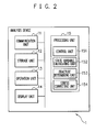
- Fig. 2 is a diagram illustrating an example of a schematic structure of an analysis device 1 which performs such an analysis.
- the analysis device 1 executes various kinds of processes with reference to data also stored in the storage unit 12 and/or data stored in another not-illustrated device. Further, the analysis device 1 executes the various kinds of processes according to an instruction input by a user via an operation unit 13 and outputs the results to a display unit 14.
- the analysis device 1 includes a communication unit 11, the storage unit 12, the operation unit 13, the display unit 14, and a processing unit 15.
- the communication unit 11 includes a communication interface circuit for connecting the analysis device 1 to a not-illustrated network. Further, the communication unit 11 supplies the processing unit 15 with data received from not-illustrated other devices via the network. Further, the communication unit 11 transmits data supplied from the processing unit 15, to other devices via the network.
- the storage unit 12 includes at least one of, for example, a semiconductor memory, a magnetic disk device, and an optical disk device.
- the storage unit 12 stores an operating system program, driver programs, application programs, data, and so on which are used in the processing in the processing unit 15.
- the storage unit 12 stores, as the driver programs, an input device driver program which controls the operation unit 13, an output device driver program which controls the display unit 14, and the like.
- the storage unit 12 stores, as the application programs, an application program which creates analysis data, an application program which performs the deformation analysis of a material, and the like.
- the storage unit 12 stores, as the data, the analysis data indicating a target, a condition, and so on of the analysis, limit curve data indicating a fracture limit stress curve, end time data indicating an end time of the analysis, and the like. Further, the storage unit 12 stores, as other data, evaluation point data indicating evaluation points of each element, a time counter indicating a current time, nodal coordinate data indicating coordinates of each nodal point at each point in time, evaluation point state data indicating states of the respective evaluation points at each point in time, and the like. Further, the storage unit 12 may temporarily store temporary data involved in a predetermined process.
- the analysis data are data indicating the target, the condition, and so on of the analysis, and include, for example, analysis model data indicating a shape of a material, material property data indicating material constants, boundary condition data indicating a boundary condition, analysis control parameters involved in the control of the analysis, and so on.
- the analysis data may be manually input by a user via the operation unit 13, or may be automatically created by the processing unit 15 based on the application program which creates the analysis data.
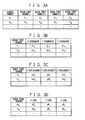
- the analysis model data are data indicating the shape of the material and include, for example, element structure data ( Fig. 3A ) indicating the nodal points of each of the elements of the material, nodal coordinate data ( Fig. 3B ) indicating the coordinates of each of the nodal points, and so on.
- Fig 3A to Fig. 3D are charts illustrating examples of data structures of various kinds of data.
- Fig. 3A illustrates an example of the data structure of the element structure data.
- the element structure data includes, for each of the elements, the element number, the numbers of the nodal points that the relevant element has, and so on.
- Fig. 3B illustrates an example of the data structure of the nodal coordinate data.
- the nodal coordinate data includes, for each of the nodal points, the nodal point number, an X coordinate, a Y coordinate, and a Z coordinate of the relevant nodal point, and so on.
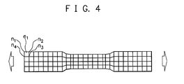
- Fig. 4 is a view illustrating an example of a test piece displayed based on the analysis model data.
- Fig. 4 a plane view of JIS (Japanese Industrial Standards) No. 5 test piece which is modeled by using a hexahedral element is illustrated.
- JIS Japanese Industrial Standards
- the material property data is data indicating the material constants and includes, for example, density, a Young's modulus, a Poisson's ratio, and so on.
- the stress-strain relation is not limited to this, and may be others (for example, the Voce rule). Further, it does not need to be a form of a constitutive equation, but the stress-strain relation may be approximated poly-linearly and the resultant value may be directly input.
- D' damage speed
- D c threshold value of a damage degree based on which the presence of the fracture is determined
- the boundary condition data are data indicating the boundary condition and include, for example, displacement condition data ( Fig. 3C ) indicating a displacement condition, load condition data ( Fig. 3D ) indicating a load condition, and so on.
- Fig. 3C illustrates an example of the data structure of the displacement condition data.
- the displacement condition data includes, for each of the nodal points, the nodal point number, X displacement, Y displacement, and Z displacement of the relevant nodal point, and so on.
- Fig. 3D illustrates an example of the data structure of the load condition data.
- the load condition data includes, for each of the nodal points, the nodal point number, an X load, a Y load, and a Z load of the relevant nodal point, and so on.
- the operation unit 13 may be any device provided that it is capable of operating the analysis device 1, and is, for example, a keyboard, a touch pad, or the like. A user can input characters, numbers, and so on via the operation unit 13. When operated by a user, the operation unit 13 generates a signal corresponding to this operation. Then, the generated signal is supplied to the processing unit 15 as an instruction of the user.
- the display unit 14 may be any device provided that it is capable of displaying video pictures, images, characters, and so on, and is, for example, a liquid crystal display, an organic EL (Electro-Luminescence) display, or the like.
- the display unit 14 displays a video picture, an image, a character, and so on according to video picture data, image data, character data, and so on, respectively, which are supplied from the processing unit 15.
- the processing unit 15 is provided with one processor or more and peripheral circuits thereof.
- the processing unit 15 centrally controls the whole operation of the analysis device 1 and is, for example, a CPU (Central Processing Unit).
- the processing unit 15 controls the operations of the communication unit 11, the display unit 14, and so on so that various kinds of processes of the analysis device 1 are executed in appropriate procedures according to the programs stored in the storage unit 12, the operation of the operation unit 13, or the like.
- the processing unit 15 executes the processes based on the programs (the operating system programs, the driver programs, the application programs, and so on) stored in the storage unit 12. Further, the processing unit 12 is capable of executing a plurality of programs (application programs and so on) in parallel.
- the processing unit 12 includes a control unit 151, a state variable calculating unit 152, a fracture determining unit 153, and a stress correcting unit 154. These units are functional modules realized by programs executed by the processor included in the processing unit 15. Alternatively, these units may be implemented in the analysis device 1 as firmware.
- the analysis device 1 starts the process based on this program.
- the control unit 151 realized by this program initializes data. Specifically, the control unit 151 obtains the analysis model data from the storage unit 12, and based on the obtained analysis model data, decides a predetermined number (for example, eight) evaluation points for each element. Then, the control unit 151 creates the evaluation point data ( Fig. 5A ) indicating the decided evaluation points and stores the evaluation point data in the storage unit 12. Further, the control unit 151 reserves, in the storage unit 12, areas for storing the time counter indicating the current time, time-nodal coordinate data ( Fig. 5B ) indicating the coordinates of each nodal point at each point in time, and time-evaluation point state data ( Fig. 5C ) indicating the state of each of the evaluation points at each point in time, and initializes them to "0".
- a predetermined number for example, eight
- Fig. 5A to Fig. 5C are charts illustrating other examples of the data structures of the various kinds of data.
- Fig. 5A illustrates an example of the data structure of the evaluation point data.
- the evaluation point data includes, for each of the elements, the element number, the numbers of the evaluation points that the relevant element has, and so on.
- Fig. 5B illustrates an example of the data structure of the time-nodal coordinate data.
- the time-nodal coordinate data includes, for each of the nodal points at each point in time, the nodal point number, an X coordinate, a Y coordinate, a Z coordinate of the relevant nodal point, and so on.
- Fig. 5C illustrates an example of the data structure of the time-evaluation point state data.
- the time-evaluation point state data includes, for each of the evaluation points at each point in time, the evaluation point number, a strain and a stress of the relevant evaluation point, a fracture flag indicating whether or not a fracture has already occurred, a damage variable (damage degree), a cumulative damage speed, and so on.
- the control unit 151 instructs the state variable calculating unit 152 to execute a process and causes it to calculate the state variables (for example, the strain, the stress, and so on).
- the control unit 151 instructs the fracture determining unit 153 to execute a process and causes it to execute the fracture determination based on the stress FLD.
- the control unit 151 determines whether or not a fracture has occurred at any of the evaluation points. Specifically, the control unit 151 refers to the time counter stored in the storage unit 12 to obtain the time. Further, the control unit 151 uses the obtained time as a key to refer to the time-evaluation point state data stored in the storage unit 12 and specifies corresponding evaluation points. Then, the control unit 151 determines whether or not the fracture flag of any evaluation point out of the specified evaluation points indicates that the fracture has occurred.
- control unit 151 instructs the stress correcting unit 154 to execute a process and causes it to correct the stress of the evaluation point.
- the control unit 151 advances the time by one. Specifically, the control unit 151 refers to the time counter stored in the storage unit 12 to obtain the time. Further, the control unit 151 increments (+1) the obtained time to update the time. Then, the control unit 151 refers to the time counter stored in the storage unit 12 to store the updated time.
- the control unit 151 determines whether or not the end time has been reached. Specifically, the control unit 151 refers to the end time data stored in the storage unit 12 to obtain the end time. Then, the control unit 151 determines whether or not the updated time has reached the obtained end time.
- control unit 151 instructs the state variable calculating unit 152 to calculate the state variables.
- the control unit 151 outputs the analysis result. Specifically, the control unit 151 obtains the time-nodal coordinate data and the time-evaluation point state data from the storage unit 12. Then, the control unit 151 outputs the obtained time-nodal coordinate data and time-evaluation point state data to the display unit 14 in a predetermined manner. Then, the control unit 151 ends the process.
- the state variable calculating unit 152 obtains the analysis data, the evaluation point data, the time-nodal coordinate data, and the time-evaluation point state data from the storage unit 12 and causes the deformation analysis of the material to progress based on the obtained analysis data, evaluation point data, time-nodal coordinate data, and time-evaluation point state data and calculates the nodal coordinates and the state variables at the current time.
- the state variable calculating unit 152 refers to the time counter stored in the storage unit 12 to obtain the time. Further, the state variable calculating unit 152 uses a time immediately before the obtained time as a key to refer to the time-evaluation point state data stored in the storage unit 12 and obtains the stress of each of the corresponding evaluation points.
- the state variable calculating unit 152 converts the obtained stresses into loads of the respective nodal points and calculates the displacements (coordinates) of the respective nodal points based on the converted loads. Further, the state variable calculating unit 152 calculates the strains of the respective evaluation points based on the calculated displacements and calculates the stresses of the respective evaluation points based on the calculated strains.
- the state variable calculating unit 152 refers to the time-nodal coordinate data stored in the storage unit 12 and stores the calculated coordinates of the respective nodal points in correspondence to the obtained time. Further, the state variable calculating unit 152 refers to the time-evaluation point state data stored in the storage unit 12 and stores the calculated strains and stresses of the respective evaluation points in correspondence to the obtained time. Then, the state variable calculating unit 152 ends the process.
- Abaqus registered trademark
- OpenFOAM registered trademark
- the dynamic explicit method is a method of solving a dynamic balance equation (equation of motion) with an acceleration term taken into consideration, without iterative calculations.
- a dynamic balance equation equation of motion
- M is a mass matrix
- u displacement
- P is an equivalent nodal force vector
- F is a nodal external force vector.
- the fracture determining unit 153 calculates the maximum principal stress and the minimum principal stress of the relevant evaluation point based on the stress of the evaluation point calculated by the state variable calculating unit 153. Specifically, the fracture determining unit 153 refers to the time counter stored in the storage unit 12 to obtain the time. Further, the fracture determining unit 153 uses the obtained time as a key to refer to the time-evaluation point state data stored in the storage unit 12 and specifies the corresponding evaluation points. Regarding each of the specified evaluation points, the fracture determining unit 153 refers to the fracture flag of the relevant evaluation point and determines whether or not the fracture flag indicates that the fracture has occurred. Then, when the fracture flag does not indicate that the fracture has occurred, the fracture determining unit 153 extracts the stress of the evaluation point and calculates the maximum principal stress and the minimum principal stress based on the extracted stress.
- the fracture determining unit 153 determines whether or not a relation between the maximum principal stress and the minimum principal stress of the evaluation point exceeds the fracture limit stress curve. Specifically, the fracture determining unit 153 obtains the limit curve data from the storage unit 12. Then, the fracture determining unit 153 determines whether or not the relation between the maximum principal stress and the minimum principal stress of the evaluation point exceeds the fracture limit stress curve indicated by the obtained limit curve data.
- the fracture determining unit 153 determines that the fracture has occurred at the evaluation point and records this. Specifically, when the relation between the maximum principal stress and the minimum principal stress of the evaluation point exceeds the fracture limit stress curve indicated by the obtained limit curve data, the fracture determining unit 153 changes the fracture flag of the evaluation point so that it indicates that the fracture has occurred. Then, the fracture determining unit 153 ends the process.
- the stress correcting unit 154 calculates the damage speed of the relevant evaluation point. Specifically, the stress correcting unit 154 refers to the time counter stored in the storage unit 12 to obtain the time. Further, the stress correcting unit 154 uses the obtained time as a key to refer to the time-evaluation point state data stored in the storage unit 12 and specifies the corresponding evaluation points. Regarding each of the specified evaluation points, the stress correcting unit 154 refers to the fracture flag of the evaluation point to determine whether or not the fracture flag indicates that the fracture has occurred. Then, when the fracture flag indicates that the fracture has occurred, the stress correcting unit 154 extracts the number, the strain, and the stress of the evaluation point.
- the stress correcting unit 154 uses the time immediately before the obtained time and the extracted evaluation point number as keys to refer to the time-evaluation point state data stored in the storage unit 12 and specifies the corresponding evaluation point. Further, the stress correcting unit 154 extracts the damage degree of the specified evaluation point.
- the stress correcting unit 154 calculates the damage speed by using the expression 2 based on the extracted strain, stress, and damage degree.
- the stress correcting unit 154 calculates the damage degree of the evaluation point. Specifically, the stress correcting unit 154 extracts the cumulative damage speed of the specified evaluation point. Further, the stress correcting unit 154 adds the calculated damage speed to the extracted cumulative damage speed to update the cumulative damage speed. Then, the stress correcting unit 154 adds the updated cumulative damage speed to the extracted damage degree to update the damage degree. The stress correcting unit 154 stores the updated damage degree and cumulative damage speed as the damage degree and the cumulative damage speed of the evaluation point in the storage unit 12.
- the stress correcting unit 154 determines whether or not the damage degree of the evaluation point exceeds the threshold value. Specifically, the stress correcting unit 154 refers to the material property data stored in the storage unit 12 to extract the threshold value of the damage degree. Then, the stress correcting unit 154 determines whether or not the updated damage degree exceeds the extracted threshold value.
- the stress correcting unit 154 corrects (decreases) the stress of the evaluation point. Specifically, the stress correcting unit 154 calculates the correction stress by using the expression 1 based on the extracted stress and the updated damage degree. The stress correcting unit 154 stores the calculated correction stress as the stress of the evaluation point in the storage unit 12.
- the stress correcting unit 154 eliminates the element having the relevant evaluation point. Specifically, the stress correcting unit 154 uses the extracted evaluation point number as a key to refer to the evaluation point data stored in the storage unit 12 and extracts the number of the corresponding element and the numbers of the other evaluation points. Then, the stress correcting unit 154 uses the extracted element number as a key to refer to the element structure data stored in the storage unit 12 and deletes items relating to the corresponding element. Further, the stress correcting unit 154 uses the extracted element number as a key to refer to the evaluation point data stored in the storage unit 12 and deletes items relating to the corresponding element.
- the stress correcting unit 154 uses the obtained time and the extracted evaluation point numbers as keys to refer to the time-evaluation point state data stored in the storage unit 12 and changes the stresses of the corresponding evaluation points to "0". Then, the stress correcting unit 154 ends the process.
- Fig. 6A to Fig. 6C are charts illustrating examples of operation flows of the analysis device 1.
- the operation flows described below are executed mainly by the processing unit 15 in cooperation with the elements of the analysis device 1, based on the programs stored in advance in the storage unit 12.
- Fig. 6A illustrates an example of the operation flow of the control unit 151.
- Step S600 When the execution of the deformation analysis is instructed by a user via the operation unit 13, the control unit 151 initializes the data (Step S600).
- the control unit 151 instructs the state variable calculating unit 152 to execute the process and causes it to calculate the state variables (for example, strain, stress, and so on) (Step S602).
- the control unit 151 instructs the fracture determining unit 153 to execute the process and causes it to execute the fracture determination based on the stress FLD (Step S604).
- Fig. 6B illustrates an example of the operation flow of the fracture determining unit 153.
- the fracture determining unit 153 calculates the maximum principal stress and the minimum principal stress of the relevant evaluation point based on the calculated stress of the evaluation point (Step S620).
- the fracture determining unit 153 determines whether or not the relation between the maximum principal stress and the minimum principal stress of the evaluation point exceeds the fracture limit stress curve (Step S622).
- the fracture determining unit 153 records that the fracture has occurred at the evaluation point (Step S624). Then, the fracture determining unit 153 ends the process.
- control unit 151 determines whether or not the fracture has occurred at any of the evaluation points (Step S606).
- control unit 151 instructs the stress correcting unit 154 to execute the process and causes it to correct the stress of the evaluation point (Step S608).
- Fig. 6C illustrates an example of the operation flow of the stress correcting unit 154.
- the stress correcting unit 154 calculates the damage speed of the relevant evaluation point (Step S630).
- the stress correcting unit 154 calculates the damage degree of the evaluation point (Step S632).
- the stress correcting unit 154 determines whether or not the damage degree of the evaluation point exceeds the threshold value (Step S634).
- Step S634-No When the damage degree of the evaluation point does not exceed the threshold value (Step S634-No), the stress correcting unit 154 corrects the stress of the evaluation point (Step S636).
- Step S634-Yes when the damage degree of the evaluation point exceeds the threshold value (Step S634-Yes), the stress correcting unit 154 eliminates the element including the relevant evaluation point (Step S638). Then, the stress correcting unit 154 ends the process.
- Step S610 the control unit 151 advances the time by one (Step S610).
- the control unit 151 determines whether or not the end time has been reached (Step S612).
- Step S612-No the control unit 151 returns to the calculation instruction of the state variables (Step S602).
- Step S612-Yes the control unit 151 outputs the analysis result (Step S614). Then, the control unit 151 ends the process.
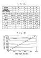
- Fig. 7A is a chart illustrating an example of the analysis parameters.
- p 1 represents a pattern where neither the fracture determination nor the rigidity decrease is performed
- p 2 represents a pattern where only the fracture determination is performed (conventional method)
- p 3 to p 5 represent patterns where both the facture determination and the rigidity decrease are performed (present method).
- p 3 to p 5 represent patterns which are different from one another in the damage-related constant (concretely, the damage speed D'). Note that the other material constants are the same in these patterns.
- Fig. 7B illustrates an example of the fracture limit stress curve common to the patterns of the analysis parameters.
- Fig. 8 is a chart illustrating an example of the analysis result.
- Fig. 8 the stress-strain relations calculated for the respective patterns of the analysis parameters are illustrated.
- the horizontal axis represents a nominal strain and the vertical axis represents a nominal stress. From the stress-strain relations illustrated in Fig. 8 , it can be confirmed that, after the fracture occurs, rigidity rapidly decreases in the pattern p 2 (conventional method) due to the elimination of the fractured element, while rigidity gradually decreases in the patterns p 3 to p 5 (present method) due to the reduction of the stress applied to the fractured element. Further, it can be also confirmed that it is possible to adjust the degree of the rigidity decrease depending on the magnitude of the damage-related constant.
- the analysis device 1 includes the units illustrated in Fig. 2 , but some of them may be included in a not-illustrated server device.
- the server device may include a storage unit corresponding to the storage unit 12 of the analysis device 1, transmit programs, data, and so on stored in this storage unit to the analysis device 1, and cause the analysis device 1 to execute the processes.
- the server device may include a storage unit and a processing unit corresponding to the storage unit 12 and the processing unit 15 of the analysis device 1, execute the processes by using programs, data, and so on stored in this storage unit, and provide only the results to the analysis device 1.
- a computer program for causing a computer to realize the functions included in the processing unit 15 may be provided in a form of being recorded in a computer-readable recording medium such as a magnetic recording medium or an optical recording medium.
- the present invention is applicable to a deformation analysis device, a deformation analysis method, and a program for executing fracture determination based on a stress FLD.
Landscapes
- Engineering & Computer Science (AREA)
- Physics & Mathematics (AREA)
- Theoretical Computer Science (AREA)
- General Physics & Mathematics (AREA)
- General Engineering & Computer Science (AREA)
- Evolutionary Computation (AREA)
- Geometry (AREA)
- Computer Hardware Design (AREA)
- Data Mining & Analysis (AREA)
- Mathematical Physics (AREA)
- Software Systems (AREA)
- Mathematical Analysis (AREA)
- Databases & Information Systems (AREA)
- Pure & Applied Mathematics (AREA)
- Mathematical Optimization (AREA)
- Computational Mathematics (AREA)
- Algebra (AREA)
- Investigating Strength Of Materials By Application Of Mechanical Stress (AREA)
- Health & Medical Sciences (AREA)
- Life Sciences & Earth Sciences (AREA)
- Artificial Intelligence (AREA)
- Biomedical Technology (AREA)
- Biophysics (AREA)
- Computational Linguistics (AREA)
- General Health & Medical Sciences (AREA)
- Molecular Biology (AREA)
- Computing Systems (AREA)
Applications Claiming Priority (2)
| Application Number | Priority Date | Filing Date | Title |
|---|---|---|---|
| JP2013100418 | 2013-05-10 | ||
| PCT/JP2013/083483 WO2014181491A1 (ja) | 2013-05-10 | 2013-12-13 | 変形解析装置、変形解析方法及びプログラム |
Publications (2)
| Publication Number | Publication Date |
|---|---|
| EP2924596A1 true EP2924596A1 (de) | 2015-09-30 |
| EP2924596A4 EP2924596A4 (de) | 2016-09-14 |
Family
ID=51866983
Family Applications (1)
| Application Number | Title | Priority Date | Filing Date |
|---|---|---|---|
| EP13884149.9A Ceased EP2924596A4 (de) | 2013-05-10 | 2013-12-13 | Verformungsanalysevorrichtung, verformungsanalyseverfahren und programm |
Country Status (7)
| Country | Link |
|---|---|
| US (1) | US10331809B2 (de) |
| EP (1) | EP2924596A4 (de) |
| JP (1) | JP5644985B1 (de) |
| KR (1) | KR101623693B1 (de) |
| CN (1) | CN104919460B (de) |
| TW (1) | TWI516968B (de) |
| WO (1) | WO2014181491A1 (de) |
Cited By (1)
| Publication number | Priority date | Publication date | Assignee | Title |
|---|---|---|---|---|
| CN110501464A (zh) * | 2019-09-09 | 2019-11-26 | 中国石油大学(华东) | 一种海洋立管损伤程度及损伤位置识别方法及系统 |
Families Citing this family (14)
| Publication number | Priority date | Publication date | Assignee | Title |
|---|---|---|---|---|
| US10977399B2 (en) * | 2015-09-22 | 2021-04-13 | Livermore Software Technology Corporation | Methods and systems for conducting a time-marching numerical simulation of a deep drawing metal forming process for manufacturing a product or part |
| JP6645509B2 (ja) * | 2015-11-04 | 2020-02-14 | 富士通株式会社 | 構造解析方法、及び構造解析プログラム |
| WO2018138943A1 (ja) * | 2017-01-25 | 2018-08-02 | パナソニックIpマネジメント株式会社 | 剛性測定装置および剛性測定方法 |
| JP2019003301A (ja) * | 2017-06-13 | 2019-01-10 | ソニーセミコンダクタソリューションズ株式会社 | 情報処理装置、情報処理方法、及びプログラム |
| JP6988599B2 (ja) * | 2018-03-14 | 2022-01-05 | トヨタ自動車株式会社 | 解析装置 |
| JP7158175B2 (ja) * | 2018-05-16 | 2022-10-21 | 日鉄ソリューションズ株式会社 | 情報処理装置、システム、情報処理方法及びプログラム |
| JP6958521B2 (ja) * | 2018-09-14 | 2021-11-02 | Jfeスチール株式会社 | 応力−ひずみ関係推定方法 |
| US11244095B2 (en) * | 2019-05-31 | 2022-02-08 | Livermore Software Technology Corporation | Numerically estimating a pre-stamped shape of a workpiece used for manufacturing a product/part with deep draw metal stamping |
| CN110749510B (zh) * | 2019-09-30 | 2022-05-10 | 武汉钢铁有限公司 | 基于有限元仿真检测金属材料弯曲性能的方法 |
| CN110926973B (zh) * | 2019-11-27 | 2022-06-21 | 江西省水利科学研究院 | 循环荷载下混凝土损伤积累分析方法 |
| CN113849919A (zh) * | 2020-06-26 | 2021-12-28 | 汽车成型工程有限公司 | 用于分析制造工序的模拟结果的方法 |
| CA3241053A1 (en) * | 2022-03-01 | 2023-09-07 | Rei Honma | Core design apparatus, core design method, and program |
| CN116756821B (zh) * | 2023-06-16 | 2024-06-11 | 长沙理工大学 | 一种基于耦合模拟的桩基损伤预警方法及系统 |
| CN117556671B (zh) * | 2023-11-24 | 2024-04-30 | 中国石油大学(华东) | 爆炸条件下临氢金属承压结构动态损伤与断裂预测方法 |
Family Cites Families (10)
| Publication number | Priority date | Publication date | Assignee | Title |
|---|---|---|---|---|
| US7027048B2 (en) * | 2002-05-31 | 2006-04-11 | Ugs Corp. | Computerized deformation analyzer |
| KR100517857B1 (ko) * | 2004-12-16 | 2005-09-30 | (주)프론틱스 | 연속압입시험법을 이용한 잔류응력 측정방법 |
| KR101070163B1 (ko) * | 2005-06-30 | 2011-10-05 | 아르셀러 프랑스 | 부재의 설계 방법, 부재의 설계 장치 및 컴퓨터 프로그램을 기록한 컴퓨터로 판독 가능한 기록 매체 |
| JP2007152407A (ja) | 2005-12-07 | 2007-06-21 | Fusahito Yoshida | プレス成形における成形割れ予測方法および予測装置 |
| CN101379381B (zh) * | 2006-02-01 | 2012-08-22 | 新日本制铁株式会社 | 断裂预测方法 |
| JP4855947B2 (ja) | 2007-01-11 | 2012-01-18 | 富士通株式会社 | き裂進展評価装置、き裂進展評価方法及びき裂進展評価プログラム |
| JP4329848B2 (ja) | 2007-06-15 | 2009-09-09 | トヨタ自動車株式会社 | 構造解析装置および構造解析方法 |
| BRPI0923582B8 (pt) * | 2008-12-25 | 2021-08-17 | Nippon Steel & Sumitomo Metal Corp | método e dispositivo para análise de uma causa de recuperação elástica em um produto formado |
| JP2011053807A (ja) | 2009-08-31 | 2011-03-17 | Fuji Heavy Ind Ltd | 衝突解析装置及び衝突解析方法 |
| KR101227295B1 (ko) * | 2010-04-07 | 2013-01-30 | 신닛테츠스미킨 카부시키카이샤 | 파단 판정 방법, 파단 판정 장치, 프로그램 및 컴퓨터 판독 가능한 기록 매체 |
-
2013
- 2013-12-13 JP JP2014526316A patent/JP5644985B1/ja active Active
- 2013-12-13 EP EP13884149.9A patent/EP2924596A4/de not_active Ceased
- 2013-12-13 WO PCT/JP2013/083483 patent/WO2014181491A1/ja not_active Ceased
- 2013-12-13 KR KR1020157016212A patent/KR101623693B1/ko active Active
- 2013-12-13 US US14/648,951 patent/US10331809B2/en active Active
- 2013-12-13 CN CN201380068681.9A patent/CN104919460B/zh active Active
- 2013-12-13 TW TW102146086A patent/TWI516968B/zh not_active IP Right Cessation
Cited By (2)
| Publication number | Priority date | Publication date | Assignee | Title |
|---|---|---|---|---|
| CN110501464A (zh) * | 2019-09-09 | 2019-11-26 | 中国石油大学(华东) | 一种海洋立管损伤程度及损伤位置识别方法及系统 |
| CN110501464B (zh) * | 2019-09-09 | 2022-01-21 | 中国石油大学(华东) | 一种海洋立管损伤程度及损伤位置识别方法及系统 |
Also Published As
| Publication number | Publication date |
|---|---|
| WO2014181491A1 (ja) | 2014-11-13 |
| EP2924596A4 (de) | 2016-09-14 |
| CN104919460A (zh) | 2015-09-16 |
| KR101623693B1 (ko) | 2016-05-23 |
| US20150310143A1 (en) | 2015-10-29 |
| JP5644985B1 (ja) | 2014-12-24 |
| KR20150087349A (ko) | 2015-07-29 |
| TW201443677A (zh) | 2014-11-16 |
| CN104919460B (zh) | 2019-01-22 |
| US10331809B2 (en) | 2019-06-25 |
| TWI516968B (zh) | 2016-01-11 |
| JPWO2014181491A1 (ja) | 2017-02-23 |
Similar Documents
| Publication | Publication Date | Title |
|---|---|---|
| EP2924596A1 (de) | Verformungsanalysevorrichtung, verformungsanalyseverfahren und programm | |
| JP2016004543A (ja) | 有限要素解析装置、該方法及び該プログラム | |
| US10156506B2 (en) | Residual stress estimation method and residual stress estimation device | |
| JP2008142774A (ja) | 応力−ひずみ関係シミュレート方法、応力−ひずみ関係シミュレーションシステム、応力−ひずみ関係シミュレーションプログラム、及び当該プログラムを記録した記録媒体 | |
| US20210357544A1 (en) | Method and apparatus for analyzing sensitivity of automotive body parts and method for determining material property of automotive body parts | |
| JP2003270060A (ja) | 応力ひずみ解析システム及びそれに用いる応力ひずみ解析方法並びにそのプログラム | |
| WO2013042600A1 (ja) | Chabocheモデルを用いた応力-ひずみ関係シミュレーション方法、応力-ひずみ関係シミュレーションシステム、応力-ひずみ関係シミュレーションプログラム | |
| JP2009264797A (ja) | 多結晶材料の変形特性予測方法及び装置、並びにプログラム及び記録媒体 | |
| JP6325865B2 (ja) | 部品の破断判定方法、システム及びプログラム、並びに、理論成形限界線図の作成方法 | |
| JP2014077700A (ja) | 力学的物理量の算出方法及び装置 | |
| EP2787457B1 (de) | Kontaktsimulationsverfahren für Gummimaterial | |
| JP4433769B2 (ja) | 非線形有限要素解析装置及び方法、コンピュータプログラム、記録媒体 | |
| JP6070277B2 (ja) | 装置、その制御方法、及びその制御プログラム | |
| JP5737059B2 (ja) | プレス成形シミュレーション解析方法及び装置 | |
| JP5210085B2 (ja) | デフォーム発生予測方法 | |
| CN114297896B (zh) | 一种着陆碰撞刚度确定方法、装置、设备和介质 | |
| JP2003232688A (ja) | 二次元応力場計測システム及び二次元応力場計測プログラム | |
| JP2001208641A (ja) | 地震応答解析方法 | |
| JP7846512B2 (ja) | 画像処理装置、画像処理方法及びプログラム | |
| US20060038813A1 (en) | Image processing program and image processing apparatus | |
| JP7820639B2 (ja) | 構造体設計支援装置、構造体設計支援方法及び構造体設計支援プログラム | |
| CN112836400A (zh) | 一种岸桥地震模型的建立方法、装置、设备及存储介质 | |
| KR102446945B1 (ko) | 고정식 플랫폼의 동력학 해석을 위한 모드유효질량의 증가 방법 | |
| JP4441397B2 (ja) | 地震応答解析装置、地震応答解析方法及び地震応答解析プログラム | |
| JP2002056037A (ja) | 接触解析装置 |
Legal Events
| Date | Code | Title | Description |
|---|---|---|---|
| PUAI | Public reference made under article 153(3) epc to a published international application that has entered the european phase |
Free format text: ORIGINAL CODE: 0009012 |
|
| 17P | Request for examination filed |
Effective date: 20150625 |
|
| AK | Designated contracting states |
Kind code of ref document: A1 Designated state(s): AL AT BE BG CH CY CZ DE DK EE ES FI FR GB GR HR HU IE IS IT LI LT LU LV MC MK MT NL NO PL PT RO RS SE SI SK SM TR |
|
| AX | Request for extension of the european patent |
Extension state: BA ME |
|
| DAX | Request for extension of the european patent (deleted) | ||
| RA4 | Supplementary search report drawn up and despatched (corrected) |
Effective date: 20160812 |
|
| RIC1 | Information provided on ipc code assigned before grant |
Ipc: G01N 3/00 20060101ALI20160808BHEP Ipc: G06F 17/50 20060101AFI20160808BHEP |
|
| RAP1 | Party data changed (applicant data changed or rights of an application transferred) |
Owner name: NIPPON STEEL CORPORATION |
|
| STAA | Information on the status of an ep patent application or granted ep patent |
Free format text: STATUS: EXAMINATION IS IN PROGRESS |
|
| 17Q | First examination report despatched |
Effective date: 20191204 |
|
| REG | Reference to a national code |
Ref country code: DE Ref legal event code: R003 |
|
| STAA | Information on the status of an ep patent application or granted ep patent |
Free format text: STATUS: THE APPLICATION HAS BEEN REFUSED |
|
| 18R | Application refused |
Effective date: 20221005 |