EP2924686B1 - Circuit de commande pour contrôle actif du bruit et procédé pour contrôle actif du bruit - Google Patents
Circuit de commande pour contrôle actif du bruit et procédé pour contrôle actif du bruit Download PDFInfo
- Publication number
- EP2924686B1 EP2924686B1 EP14162336.3A EP14162336A EP2924686B1 EP 2924686 B1 EP2924686 B1 EP 2924686B1 EP 14162336 A EP14162336 A EP 14162336A EP 2924686 B1 EP2924686 B1 EP 2924686B1
- Authority
- EP
- European Patent Office
- Prior art keywords
- signal
- audio signal
- speaker
- noise
- compensation
- Prior art date
- Legal status (The legal status is an assumption and is not a legal conclusion. Google has not performed a legal analysis and makes no representation as to the accuracy of the status listed.)
- Active
Links
Images
Classifications
-
- H—ELECTRICITY
- H04—ELECTRIC COMMUNICATION TECHNIQUE
- H04R—LOUDSPEAKERS, MICROPHONES, GRAMOPHONE PICK-UPS OR LIKE ACOUSTIC ELECTROMECHANICAL TRANSDUCERS; ELECTRIC HEARING AIDS; PUBLIC ADDRESS SYSTEMS
- H04R3/00—Circuits for transducers
- H04R3/04—Circuits for transducers for correcting frequency response
-
- G—PHYSICS
- G10—MUSICAL INSTRUMENTS; ACOUSTICS
- G10K—SOUND-PRODUCING DEVICES; METHODS OR DEVICES FOR PROTECTING AGAINST, OR FOR DAMPING, NOISE OR OTHER ACOUSTIC WAVES IN GENERAL; ACOUSTICS NOT OTHERWISE PROVIDED FOR
- G10K11/00—Methods or devices for transmitting, conducting or directing sound in general; Methods or devices for protecting against, or for damping, noise or other acoustic waves in general
- G10K11/16—Methods or devices for protecting against, or for damping, noise or other acoustic waves in general
- G10K11/175—Methods or devices for protecting against, or for damping, noise or other acoustic waves in general using interference effects; Masking sound
- G10K11/178—Methods or devices for protecting against, or for damping, noise or other acoustic waves in general using interference effects; Masking sound by electro-acoustically regenerating the original acoustic waves in anti-phase
- G10K11/1787—General system configurations
- G10K11/17875—General system configurations using an error signal without a reference signal, e.g. pure feedback
-
- G—PHYSICS
- G10—MUSICAL INSTRUMENTS; ACOUSTICS
- G10K—SOUND-PRODUCING DEVICES; METHODS OR DEVICES FOR PROTECTING AGAINST, OR FOR DAMPING, NOISE OR OTHER ACOUSTIC WAVES IN GENERAL; ACOUSTICS NOT OTHERWISE PROVIDED FOR
- G10K11/00—Methods or devices for transmitting, conducting or directing sound in general; Methods or devices for protecting against, or for damping, noise or other acoustic waves in general
- G10K11/16—Methods or devices for protecting against, or for damping, noise or other acoustic waves in general
- G10K11/175—Methods or devices for protecting against, or for damping, noise or other acoustic waves in general using interference effects; Masking sound
- G10K11/178—Methods or devices for protecting against, or for damping, noise or other acoustic waves in general using interference effects; Masking sound by electro-acoustically regenerating the original acoustic waves in anti-phase
- G10K11/1781—Methods or devices for protecting against, or for damping, noise or other acoustic waves in general using interference effects; Masking sound by electro-acoustically regenerating the original acoustic waves in anti-phase characterised by the analysis of input or output signals, e.g. frequency range, modes, transfer functions
- G10K11/17821—Methods or devices for protecting against, or for damping, noise or other acoustic waves in general using interference effects; Masking sound by electro-acoustically regenerating the original acoustic waves in anti-phase characterised by the analysis of input or output signals, e.g. frequency range, modes, transfer functions characterised by the analysis of the input signals only
- G10K11/17825—Error signals
-
- G—PHYSICS
- G10—MUSICAL INSTRUMENTS; ACOUSTICS
- G10K—SOUND-PRODUCING DEVICES; METHODS OR DEVICES FOR PROTECTING AGAINST, OR FOR DAMPING, NOISE OR OTHER ACOUSTIC WAVES IN GENERAL; ACOUSTICS NOT OTHERWISE PROVIDED FOR
- G10K11/00—Methods or devices for transmitting, conducting or directing sound in general; Methods or devices for protecting against, or for damping, noise or other acoustic waves in general
- G10K11/16—Methods or devices for protecting against, or for damping, noise or other acoustic waves in general
- G10K11/175—Methods or devices for protecting against, or for damping, noise or other acoustic waves in general using interference effects; Masking sound
- G10K11/178—Methods or devices for protecting against, or for damping, noise or other acoustic waves in general using interference effects; Masking sound by electro-acoustically regenerating the original acoustic waves in anti-phase
- G10K11/1781—Methods or devices for protecting against, or for damping, noise or other acoustic waves in general using interference effects; Masking sound by electro-acoustically regenerating the original acoustic waves in anti-phase characterised by the analysis of input or output signals, e.g. frequency range, modes, transfer functions
- G10K11/17821—Methods or devices for protecting against, or for damping, noise or other acoustic waves in general using interference effects; Masking sound by electro-acoustically regenerating the original acoustic waves in anti-phase characterised by the analysis of input or output signals, e.g. frequency range, modes, transfer functions characterised by the analysis of the input signals only
- G10K11/17827—Desired external signals, e.g. pass-through audio such as music or speech
-
- G—PHYSICS
- G10—MUSICAL INSTRUMENTS; ACOUSTICS
- G10K—SOUND-PRODUCING DEVICES; METHODS OR DEVICES FOR PROTECTING AGAINST, OR FOR DAMPING, NOISE OR OTHER ACOUSTIC WAVES IN GENERAL; ACOUSTICS NOT OTHERWISE PROVIDED FOR
- G10K11/00—Methods or devices for transmitting, conducting or directing sound in general; Methods or devices for protecting against, or for damping, noise or other acoustic waves in general
- G10K11/16—Methods or devices for protecting against, or for damping, noise or other acoustic waves in general
- G10K11/175—Methods or devices for protecting against, or for damping, noise or other acoustic waves in general using interference effects; Masking sound
- G10K11/178—Methods or devices for protecting against, or for damping, noise or other acoustic waves in general using interference effects; Masking sound by electro-acoustically regenerating the original acoustic waves in anti-phase
- G10K11/1785—Methods, e.g. algorithms; Devices
- G10K11/17853—Methods, e.g. algorithms; Devices of the filter
-
- G—PHYSICS
- G10—MUSICAL INSTRUMENTS; ACOUSTICS
- G10K—SOUND-PRODUCING DEVICES; METHODS OR DEVICES FOR PROTECTING AGAINST, OR FOR DAMPING, NOISE OR OTHER ACOUSTIC WAVES IN GENERAL; ACOUSTICS NOT OTHERWISE PROVIDED FOR
- G10K11/00—Methods or devices for transmitting, conducting or directing sound in general; Methods or devices for protecting against, or for damping, noise or other acoustic waves in general
- G10K11/16—Methods or devices for protecting against, or for damping, noise or other acoustic waves in general
- G10K11/175—Methods or devices for protecting against, or for damping, noise or other acoustic waves in general using interference effects; Masking sound
- G10K11/178—Methods or devices for protecting against, or for damping, noise or other acoustic waves in general using interference effects; Masking sound by electro-acoustically regenerating the original acoustic waves in anti-phase
- G10K11/1787—General system configurations
- G10K11/17885—General system configurations additionally using a desired external signal, e.g. pass-through audio such as music or speech
-
- H—ELECTRICITY
- H04—ELECTRIC COMMUNICATION TECHNIQUE
- H04R—LOUDSPEAKERS, MICROPHONES, GRAMOPHONE PICK-UPS OR LIKE ACOUSTIC ELECTROMECHANICAL TRANSDUCERS; ELECTRIC HEARING AIDS; PUBLIC ADDRESS SYSTEMS
- H04R1/00—Details of transducers, loudspeakers or microphones
- H04R1/10—Earpieces; Attachments therefor ; Earphones; Monophonic headphones
- H04R1/1083—Reduction of ambient noise
-
- G—PHYSICS
- G10—MUSICAL INSTRUMENTS; ACOUSTICS
- G10K—SOUND-PRODUCING DEVICES; METHODS OR DEVICES FOR PROTECTING AGAINST, OR FOR DAMPING, NOISE OR OTHER ACOUSTIC WAVES IN GENERAL; ACOUSTICS NOT OTHERWISE PROVIDED FOR
- G10K2210/00—Details of active noise control [ANC] covered by G10K11/178 but not provided for in any of its subgroups
- G10K2210/30—Means
- G10K2210/301—Computational
- G10K2210/3016—Control strategies, e.g. energy minimization or intensity measurements
-
- G—PHYSICS
- G10—MUSICAL INSTRUMENTS; ACOUSTICS
- G10K—SOUND-PRODUCING DEVICES; METHODS OR DEVICES FOR PROTECTING AGAINST, OR FOR DAMPING, NOISE OR OTHER ACOUSTIC WAVES IN GENERAL; ACOUSTICS NOT OTHERWISE PROVIDED FOR
- G10K2210/00—Details of active noise control [ANC] covered by G10K11/178 but not provided for in any of its subgroups
- G10K2210/30—Means
- G10K2210/301—Computational
- G10K2210/3023—Estimation of noise, e.g. on error signals
- G10K2210/30232—Transfer functions, e.g. impulse response
-
- G—PHYSICS
- G10—MUSICAL INSTRUMENTS; ACOUSTICS
- G10K—SOUND-PRODUCING DEVICES; METHODS OR DEVICES FOR PROTECTING AGAINST, OR FOR DAMPING, NOISE OR OTHER ACOUSTIC WAVES IN GENERAL; ACOUSTICS NOT OTHERWISE PROVIDED FOR
- G10K2210/00—Details of active noise control [ANC] covered by G10K11/178 but not provided for in any of its subgroups
- G10K2210/30—Means
- G10K2210/301—Computational
- G10K2210/3028—Filtering, e.g. Kalman filters or special analogue or digital filters
-
- H—ELECTRICITY
- H04—ELECTRIC COMMUNICATION TECHNIQUE
- H04R—LOUDSPEAKERS, MICROPHONES, GRAMOPHONE PICK-UPS OR LIKE ACOUSTIC ELECTROMECHANICAL TRANSDUCERS; ELECTRIC HEARING AIDS; PUBLIC ADDRESS SYSTEMS
- H04R2430/00—Signal processing covered by H04R, not provided for in its groups
-
- H—ELECTRICITY
- H04—ELECTRIC COMMUNICATION TECHNIQUE
- H04R—LOUDSPEAKERS, MICROPHONES, GRAMOPHONE PICK-UPS OR LIKE ACOUSTIC ELECTROMECHANICAL TRANSDUCERS; ELECTRIC HEARING AIDS; PUBLIC ADDRESS SYSTEMS
- H04R2460/00—Details of hearing devices, i.e. of ear- or headphones covered by H04R1/10 or H04R5/033 but not provided for in any of their subgroups, or of hearing aids covered by H04R25/00 but not provided for in any of its subgroups
- H04R2460/01—Hearing devices using active noise cancellation
Definitions
- the present invention relates to a control circuit for active noise control and to a method for active noise control for sound reproduction devices, in particular for headphones.
- ANC active noise control
- the goal of ANC is to reduce or remove unwanted external noise from the sound impression of a user.
- a microphone is situated at or inside the sound reproduction device recording sound corresponding to the sound or music received by the user including noise or other unwanted external sounds.
- the sound received by the microphone is evaluated and a correction signal is produced in order to minimize the effect of the environmental noise or other disturbing sounds.
- Document US 2011/0299695 A1 discloses in its Figure 5 a feed forward ANC circuit comprising a speaker, an error microphone, a mixer, a second filter and a differencing unit.
- the mixer combines an audio signal with an anti-noise signal.
- the audio signal is also fed to the second filter and the combined signal is fed to the speaker.
- a signal generated by the second filter is subtracted from a signal generated by the speaker and the error microphone resulting in an estimated noise signal.
- An anti-noise filter generates the anti-noise signal based on an ambient noise signal received by a separate reference microphone.
- the estimated noise signal is supplied to the adaptive filter controller for adjusting the anti-noise filter.
- a further correction signal is generated on the basis of an audio input signal.
- the further correction signal is then used within an ANC arrangement to reduce unwanted effects due to the processing of the audio input signal. In this way an improved sound reproduction, for example in a certain frequency range, in particular in a low frequency range, is achieved.
- control circuit for ANC, according to the improved concept, is designed to be coupled to a speaker and to an ANC microphone.
- the speaker generates a speaker signal on the basis of an amplified audio signal while the ANC microphone generates a disturbed audio signal on the basis of ambient noise and the speaker signal.
- the control circuit comprises a first mixer that is configured to generate an intermediate audio signal by superposing an audio signal and a first compensation signal.
- the control circuit further comprises a first amplifier configured to generate the amplified audio signal based on the intermediate audio signal.
- the control circuit further comprises a compensation unit, for example implemented as a filter network.
- the compensation unit is configured to generate a second compensation signal based on the audio signal. To this end the compensation unit applies filter operations to the audio signal.
- a tuning unit is coupled to the ANC microphone and to the compensation unit.
- the tuning unit is configured to generate a compensated audio signal on the basis of the disturbed audio signal and the second compensation signal.
- the control circuit comprises an ANC filter configured to generate the first compensation signal by applying filter operations to the compensated audio signal.
- the ANC microphone may be for example a digital microphone, a dynamic microphone, a condenser microphone, an electret microphone, a piezo microphone or another type of microphone.
- the speaker signal corresponds to the sound the user actually is intended to hear.
- the ambient noise representing for example environmental noise or other unwanted external sounds
- the disturbed audio signal corresponds approximately to the sound the user would actually hear without ANC.
- the tuning unit uses the second compensation signal in order to reduce, or in an ideal case totally remove, residues of the audio signal from the disturbed audio signal. That means that, in an ideal case, the compensated audio signal contains only information about the processed ambient noise but not about the processed audio signal.
- the compensation unit emulates the information about the processed audio signal contained within the disturbed audio signal.
- a phase delay may be added during the generation of the second compensation signal to account for the fact that there is a time delay between the disturbed audio signal and the second compensation signal arriving at the tuning unit.
- the ANC filter applies filter operations to the compensated audio signal.
- the result is the first compensation signal being superposed with the audio signal by the first mixer to account for example for environmental noises and to reduce, or in an ideal case cancel, the effect of the ambient noise.
- the filter operations applied by the ANC filter may for example also account for details of the sound transmission from the speaker to the ear of a user and differences to the sound transmission from the speaker to the ANC microphone, respectively.
- a spatial arrangement of the speaker with respect to the ANC microphone on one hand and with respect to the ear on the other hand may be incorporated by the ANC filter.
- Such aspects may for example be relevant in view of spatial variations of the superposition of the speaker signal and the ambient noise.
- the first mixer may for example be implemented as an adder essentially adding the first compensation signal to the audio signal.
- the filter operations applied by the ANC filter to the compensated audio signal comprise for example an effective inversion.
- the first mixer may for example be implemented as a subtractor, as an adder-subtractor or as an adder with one inverted and one non-inverted input.
- the filter operations applied to the audio signal by the compensation unit implement a transfer function.
- the transfer function characterizes effects on a signal due to at least one of the following: the first amplifier, the speaker, the ANC microphone and a sound transmission from the speaker to the ANC microphone.
- the intention herefore is for example to emulate the information about the processed and/or transmitted audio signal contained in the disturbed audio signal.
- the generation of the second compensation signal is not affected by the ambient noise.
- the transfer function implemented by the compensation unit may for example be determined during the production and/or calibration of the control circuit and/or the sound reproducing device. To this end, for example, a test signal may be compared with a signal resulting from the test signal being accordingly processed by the respective components.
- the determination of the transfer function may for example also comprise modelling of sound transmission in the sound reproducing device.
- the tuning unit comprises a second mixer.
- the second mixer is configured to generate an intermediate noise signal by superposing the second compensation signal and a signal based on the disturbed audio signal.
- the second mixer is configured to subtract the second compensation signal from the signal based on the disturbed audio signal.
- the tuning unit is configured to generate the compensated audio signal on the basis of the intermediate noise signal.
- the second mixer may for example be implemented as a subtractor, as an adder-subtractor or as an adder with one inverted and one non-inverted input.
- the second mixer may be implemented as an adder.
- the filter operations applied to the audio signal by the compensation unit comprise for example an effective inversion.
- the tuning unit comprises a second amplifier in addition to the second mixer.
- the second amplifier is configured to generate an adjusted disturbed audio signal on the basis of the disturbed audio signal.
- the second mixer is configured to generate an intermediate noise signal by superposing the adjusted disturbed audio signal and the second compensation signal, in particular by subtracting the second compensation signal from the adjusted disturbed audio signal.
- the gain factor of the second amplifier is tuneable, for example tuneable during production and/or calibration of the control circuit and/or the sound reproducing device.
- the second amplifier is used to compensate tolerances of for example the speaker and/or the ANC microphone. Commonly, respective tolerances lie, for example, in the order of several decibels, for example in the order of 1db-10db or around 3db.
- the disturbed audio signal is adjusted accordingly to the second compensation signal by the second amplifier.
- the second amplifier may, for example, be used to control the general performance level of noise reduction in the control circuit.
- the tuning unit further comprises a third amplifier configured to generate the compensated audio signal by amplification or attenuation of the intermediate noise signal.
- Such implementation has the advantage that the adjustment of the adjusted disturbed audio signal to the second compensation signal can be performed independently from the control of the general level of noise reduction performance.
- the second amplifier is then for example used to compensate tolerances of the speaker and/or the ANC microphone.
- the third amplifier is then used to tune the level of noise reduction performance.
- the tuning unit comprises the third amplifier the amplification or attenuation of the intermediate noise signal by the third amplifier can be changed by a user during operation.
- the tuning unit comprises a test terminal to provide the intermediate noise signal to an external readout device.
- the test terminal is preferably located between the second mixer and the third amplifier.
- test terminal and the external readout device can, for example, be used for an accurate compensation of microphone and/or speaker tolerances. For example, this may be performed during production or calibration of the control circuit and/or the sound reproduction device.
- the compensation unit generates the second compensation signal utilizing a delay element.
- the delay element may add a phase delay to account for the time delay between the disturbed audio signal and the second compensation signal when arriving at the tuning unit.
- the delay element may add only a first part of the phase delay, while the second part of the phase delay is then added by other components of the compensation unit.
- the other components of the compensation unit add the first part of the phase delay and then the delay element adds the second part of the phase delay.
- the delay element comprises an all-pass filter.
- the method comprises generating an intermediate audio signal by superposing an audio signal and a first compensation signal. Furthermore, the method comprises generating the amplified audio signal by amplifying the intermediate audio signal. A second compensation signal is generated by applying filter operations to the audio signal. Then, a compensated audio signal is generated on the basis of the second compensation signal and the disturbed audio signal. Finally, the first compensation signal is generated by applying filter operations to the compensated audio signal.
- the generation of the compensated audio signal on the basis of the second compensation signal and the disturbed audio signal is performed by subtraction of the second compensation signal from a signal based on the disturbed audio signal.
- the application of filter operations to the audio signal is perfomed implementing a transfer function.
- the transfer function characterizes effects on a signal due to at least one of the following: the first amplifier, the speaker, the ANC microphone and a sound transmission from the speaker to the ANC microphone.
- the generation of the compensated audio signal comprises generating an adjusted disturbed audio signal by amplification or attenuation of the disturbed audio signal.
- the method further comprises the generation of an intermediate noise signal by superposing the second compensation signal and the adjusted disturbed audio signal, i.e. by subtracting the second compensation signal from the adjusted disturbed audio signal.
- the generation of the second compensation signal is then performed on the basis of the intermediate noise signal.
- the generation of the compensated audio signal further comprises an amplification or attenuation of the intermediate noise signal.
- the amplification or attenuation of the intermediate noise can be performed at least partly by a user during operation.
- implementations of the method comprise providing the intermediate noise signal to an external readout device.
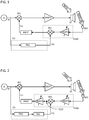
- FIG. 1 shows an exemplary embodiment of a control circuit for ANC according to the improved concept.
- the control circuit comprises a first mixer M1 and a first amplifier AMP1 that is connected to the first mixer M1. Furthermore, the first amplifier AMP1 is coupled to a speaker SP that is for example part of a sound reproducing device, for example of a headphone.
- the sound reproducing device also comprises an ANC microphone MIC positioned at a location with respect to the speaker SP that allows detecting a sound similar to the sound heard by a user.
- the control circuit comprises a tuning unit TUNE with a second amplifier AMP2 coupled to the ANC microphone MIC and a second mixer M2 connected to the second amplifier AMP2.
- the control circuit further comprises an ANC filter ANCF coupled between the first mixer M1 and the second mixer M2.
- control circuit comprises a compensation unit CU, in the shown embodiment represented by a frequency compensation unit FRU.
- the frequency compensation unit FRU is for example implemented as a filter network.
- an generating device G is coupled to the compensation unit CU and to the first mixer M1.
- the ANC microphone may be for example a digital microphone, a dynamic microphone, a condenser microphone, an electret microphone, a piezo microphone or another type of microphone.
- the first mixer may for example be designed as an adder, as a subtractor, as an adder-subtractor or as an adder with one inverted and one non-inverted input.
- the control circuit receives an audio signal IN from a generating device G.
- the audio signal IN represents in a sense a raw signal to be processed and finally used to generate sound by the speaker SP.
- the audio signal IN is fed in parallel to the first mixer M1 and to the frequency compensation unit FRU.
- the first mixer M1 superposes the audio signal IN with a first compensation signal CS1 to output an intermediate audio signal to the first amplifier AMP1.
- the first compensation signal CS1 is for example conditioned such that the resulting intermediate audio signal in a sense contains inversed information about external disturbances for example environmental noise, as described later.
- the intermediate audio signal is then for example amplified by the first amplifier AMP1 resulting in an amplified audio signal according to general requirements and/or settings of the sound reproduction.
- the amplified audio signal is processed by the speaker SP generating a speaker signal SPS.
- the speaker signal SPS is, for example, an actual superposition of sound waves propagating for example through air to reach an ear of a user.
- the ambient noise NOISE superimposes the speaker signal SPS and the sound actually reaching the ear of the user is a superposition of the ambient noise NOISE and the speaker signal SPS or a certain spatial part of the superposition, respectively.
- a different superposition, or a different spatial part of the superposition, respectively, of the ambient noise NOISE and the speaker signal SPS is detected by the ANC microphone MIC which based thereupon generates a disturbed audio signal.
- the disturbed audio signal is fed to the second amplifier AMP2.
- the second amplifier AMP2 is tuneable in that its gain factor can be adjusted.
- the second amplifier AMP2 amplifies or attenuates the disturbed audio signal to generate an adjusted disturbed audio signal that is provided to the second mixer M2.
- the second mixer also receives the second compensation signal CS2 from the frequency compensation unit FRU and superimposes both, in particular subtracts the second compensation signal CS2 from the adjusted disturbed audio signal.
- the result of the superposition is the compensated audio signal which is fed to the ANC filter ANCF.
- the second mixer is preferably implemented as a subtractor but may also be designed as an adder, as an adder-subtractor or as an adder with one inverted and one non-inverted input.
- the second compensation signal CS2 is generated by the frequency compensation unit FRU by adaption of the audio signal IN.
- the frequency compensation unit FRU applies filter operations to the audio signal IN that implement a transfer function.
- the transfer function characterizes the modifications of a signal due to signal processing and/or sound transmission.
- the transfer function characterizes effects on a signal due to at least one of the following: the first amplifier AMP1, the speaker SP, the ANC microphone MIC and a sound transmission from the speaker SP to the ANC microphone MIC.
- the second compensation signal may for example emulate the information about the processed audio signal contained within the disturbed audio signal.
- the frequency compensation unit FRU adds a phase delay with respect to the disturbed audio signal. The latter may be necessary to account for the fact that there may be a time delay between the disturbed audio signal and the second compensation signal CS2 arriving at the tuning unit TUNE.
- subtracting the second compensation signal from the adjusted disturbed audio signal by the second mixer M2 then reduces, or in an ideal case totally removes, residues of the audio signal IN from the disturbed audio signal.
- the compensated audio signal contains only information about the processed ambient noise NOISE but not about the processed audio signal IN.
- the frequency compensation unit FRU accordingly may take over an effective inversion of the audio signal.
- An addition of the second compensation signal CS2 to the adjusted disturbed audio signal corresponds then to the subtraction of the second compensation signal CS2 from the adjusted disturbed audio signal.
- the amplification or attenuation of the disturbed audio signal by the second amplifier AMP2 may serve for at least two potential purposes in the embodiment of Figure 1 . Firstly, it may provide a means to control the general performance level of noise reduction in the control circuit. For this purpose, a gain factor of the second amplifier AMP2 may for example also be changed during operation of the sound reproduction device. Secondly, the second amplifier AMP2 may be used to compensate tolerances for example of the speaker SP and/or the ANC microphone MIC. Commonly, respective tolerances lie, for example, in the order of several decibels, for example in the order of 1db-10db or around 3db.
- a tuning of the gain factor of the second amplifier AMP2 may be for example performed during procuction and/or calibration of the control circuit and/or the sound reproducing device.
- the compensated audio signal is then further processed by the ANC filter ANCF to generate the first compensation signal CS1.
- the ANC filter applies filter operations to the compensated audio signal. For example, a certain frequency range of the compensated audio signal may be suppressed.
- An adjustment of the amplitudes and/or phases of the compensated audio signal by the ANC filter ANCF is performed such that the resulting intermediate audio signal in a sense contains inversed information about external disturbances for example environmental noise.
- the first mixer M1 generating the intermediate audio signal may for example be implemented as an adder.
- the filter operations applied by the ANC filter to the compensated audio signal comprise for example an effective inversion.
- the first mixer may for example be implemented as a subtractor, as an adder-subtractor or as an adder with one inverted and one non-inverted input.
- Figure 2 shows a further exemplary embodiment of a control circuit for ANC according to the improved concept which is based on the embodiment of figure 1 .
- the embodiment shown in Figure 2 differs from the one shown in Figure 1 by a third amplifier AMP3 comprised by the tuning unit TUNE and coupled between the ANC filter ANCF and the second mixer M2 and by a test terminal TEST between the third amplifier AMP3 and the second mixer M2.
- the compensation unit comprises a delay element DEL coupled between the frequency compensation unit FRU and the second mixer M2.
- the delay element DEL takes over, or partly takes over, from the frequency compensation unit FRU the addition of the phase delay to account for the time delay between the second compensation signal CS2 and the disturbed audio signal arriving at the tuning unit TUNE or the adjusted disturbed audio signal arriving at the second mixer, respectively.
- the frequency compensation unit FRU adds only a part of the delay phase while the delay element DEL adds the remaining part of the delay phase, or the frequency compensation unit FRU does not add any part of the phase delay while the delay element DEL adds the total phase delay.
- the order of the delay element DEL and the frequency compensation unit FRU can, for example, also be opposite to the order shown in Figure 2 .
- the third amplifier AMP3 and the second amplifier AMP2 together allow for an independent control of the general performance level of ANC in the control circuit and the compensation of tolerances for example of the speaker SP and/or the ANC microphone MIC.
- the second amplifier AMP2 may be used to compensate tolerances for example, of the speaker SP and/or the ANC microphone MIC.
- the third amplifier AMP3 may be used to control the general performance level of noise reduction.
- the third amplifier AMP3 may be designed such that a gain factor of the third amplifier AMP3 may be changed during operation of the sound reproduction device.
- the third amplifier AMP3 may be included in the ANC filter ANCF instead of being part of the tuning unit TUNE. It may also be favourable to interchange the functions of the second amplifier AMP2 and the third amplifier AMP3.
- test terminal TEST allows for an external readout device to be coupled to the control circuit. This may be advantageous for exact compensation of the above mentioned tolerances for example during production and/or calibration of the control circuit and/or the sound reproduction device.
- control circuit is obtained based on the embodiment shown in Figure 1 by including not all three but only one or two of the additional components of the embodiment shown in Figure 2 , namely the delay element DEL, the third amplifier AMP3 and the test terminal TEST.
- all filter components that are comprised by an embodiment of the control circuit or by components of the control circuit may be implemented as analog filters, as digital filters or even be based on passive elements. This applies in particular to the ANC filter ANCF and the compensation unit CU and their components.
- control circuit and the methods for ANC presented herein may also be combined or split in order to meet specific requirements.
- the control circuit may, for example, be built in the sound reproducing device, for example in an earpad or another component of a headphone. Another possibility is that the control circuit is built in the generating device G.
- the generating device G may for example correspond to an electronic device, such as a mobile phone, a telephone, a television, a portable or stationary music player or a walkie-talkie.
- a control circuit according to the improved concept may, for example, be implemented in an integrated circuit.
- the integrated circuit may include also additional circuits for example for power management.
- a control circuit according to the improved concept can, for example, also be realized by adding parts of the described control circuit, particularly including the compensation unit, to another ANC arrangement.
Landscapes
- Physics & Mathematics (AREA)
- Engineering & Computer Science (AREA)
- Acoustics & Sound (AREA)
- Multimedia (AREA)
- Health & Medical Sciences (AREA)
- Audiology, Speech & Language Pathology (AREA)
- General Health & Medical Sciences (AREA)
- Signal Processing (AREA)
- Soundproofing, Sound Blocking, And Sound Damping (AREA)
- Circuit For Audible Band Transducer (AREA)
Claims (12)
- Circuit de contrôle pour le contrôle actif du bruit, ANC, à coupler à un haut-parleur (SP) générant un signal de haut-parleur (SPS) sur la base d'un signal audio amplifié et à un microphone ANC (MIC) générant un signal audio perturbé sur la base du bruit ambiant (NOISE) et du signal de haut-parleur (SPS), le circuit de contrôle comprenant- un premier mélangeur (M1) configuré pour générer un signal audio intermédiaire en superposant un signal audio (IN) et un premier signal de compensation (CS1) ;- un premier amplificateur (AMP1) configuré pour générer le signal audio amplifié sur la base du signal audio intermédiaire ;- une unité de compensation de fréquence (CU) configurée pour générer un second signal de compensation (CS2) en appliquant des opérations de filtrage au signal audio (IN) ;- une unité de syntonisation (TUNE) comprenant un second amplificateur (AMP2) configuré pour générer un signal audio perturbé ajusté sur la base du signal audio perturbé et comprenant en outre un second mélangeur (M2) configuré pour générer un signal de bruit intermédiaire en soustrayant le second signal de compensation (CS2) du signal audio perturbé ajusté, l'unité de syntonisation (TUNE) étant configurée pour générer un signal audio compensé sur la base du signal de bruit intermédiaire ; et- un filtre ANC (ANCF) configuré pour générer le premier signal de compensation (CS1) en appliquant des opérations de filtrage au signal audio compensé.
- Circuit de commande selon la revendication 1, dans lequel les opérations de filtrage appliquées au signal audio (IN) par l'unité de compensation de fréquence (CU) mettent en œuvre une fonction de transfert caractérisant les effets sur un signal dus à au moins un des suivants : le premier amplificateur (AMP1), le haut-parleur (SP), le microphone ANC (MIC) et une transmission de son du haut-parleur (SP) au microphone ANC (MIC).
- Circuit de commande selon l'une des revendications 1 ou 2, selon lequel l'unité de syntonisation comprend en outre un troisième amplificateur (AMP3) configuré pour générer le signal audio compensé par amplification ou atténuation du signal de bruit intermédiaire.
- Circuit de commande selon la revendication 3, dans lequel une étendue de l'amplification ou de l'atténuation du signal de bruit intermédiaire peut être modifiée par un utilisateur pendant le fonctionnement.
- Circuit de commande selon l'une des revendications 1 à 4, dans lequel l'unité de syntonisation (TUNE) comprend une borne de test (TEST) pour fournir le signal de bruit intermédiaire à un dispositif de lecture externe.
- Circuit de commande selon l'une des revendications 1 à 5, dans lequel l'unité de compensation de fréquence (CU) génère le second signal de compensation (CS2) en utilisant un élément de retard (DEL).
- Circuit de commande selon la revendication 6, dans lequel l'élément de retard (DEL) comprend un filtre passe-tout.
- Procédé de contrôle actif du bruit, ANC, pour un dispositif de reproduction sonore avec un haut-parleur (SP) générant un signal de haut-parleur (SPS) basé sur un signal audio amplifié et avec un microphone ANC (MIC) générant un signal audio perturbé basé sur le signal de haut-parleur (SPS) et le bruit ambiant (NOISE), dans lequel le procédé comprend- générer un signal audio intermédiaire en superposant un signal audio (IN) et un premier signal de compensation (CS1) ;- générer le signal audio amplifié en amplifiant le signal audio intermédiaire ;- générer un second signal de compensation (CS2) en appliquant des opérations de filtrage au signal audio (IN) ;- générer un signal audio perturbé ajusté par amplification ou atténuation du signal audio perturbé ;- générer un signal de bruit intermédiaire en soustrayant le second signal de compensation (CS2) du signal audio perturbé ajusté ;- générer un signal audio compensé sur la base du signal de bruit intermédiaire ; et- générer le premier signal de compensation (CS1) en appliquant des opérations de filtrage au signal audio compensé.
- Le procédé selon la revendication 8, dans lequel les opérations de filtrage appliquées au signal audio (IN) mettent en œuvre une fonction de transfert caractérisant les effets sur un signal dus à au moins un des éléments suivants: l'amplification du signal audio intermédiaire, le haut-parleur (SP), le microphone ANC (MIC) et une transmission de son du haut-parleur (SP) au microphone ANC (MIC).
- Le procédé selon l'une des revendications 8 ou 9, dans lequel la génération du signal audio compensé comprend en outre une amplification ou une atténuation du signal de bruit intermédiaire.
- Le procédé selon la revendication 10, dans lequel l'amplification ou l'atténuation du signal de bruit intermédiaire est réalisée au moins partiellement par un utilisateur en cours de fonctionnement.
- Le procédé selon l'une des revendications 8 à 11, dans lequel le procédé comprend en outre la fourniture du signal de bruit intermédiaire à un dispositif de lecture externe.
Priority Applications (4)
| Application Number | Priority Date | Filing Date | Title |
|---|---|---|---|
| EP14162336.3A EP2924686B1 (fr) | 2014-03-28 | 2014-03-28 | Circuit de commande pour contrôle actif du bruit et procédé pour contrôle actif du bruit |
| PCT/EP2015/053413 WO2015144360A1 (fr) | 2014-03-28 | 2015-02-18 | Circuit de neutralisation pour neutralisation active de bruit et méthode de neutralisation active de bruit |
| US15/129,818 US9779718B2 (en) | 2014-03-28 | 2015-02-18 | Control circuit for active noise control and method for active noise control |
| CN201580017304.1A CN106465007B (zh) | 2014-03-28 | 2015-02-18 | 用于有源噪声控制的控制电路和用于有源噪声控制的方法 |
Applications Claiming Priority (1)
| Application Number | Priority Date | Filing Date | Title |
|---|---|---|---|
| EP14162336.3A EP2924686B1 (fr) | 2014-03-28 | 2014-03-28 | Circuit de commande pour contrôle actif du bruit et procédé pour contrôle actif du bruit |
Publications (2)
| Publication Number | Publication Date |
|---|---|
| EP2924686A1 EP2924686A1 (fr) | 2015-09-30 |
| EP2924686B1 true EP2924686B1 (fr) | 2022-01-05 |
Family
ID=50389921
Family Applications (1)
| Application Number | Title | Priority Date | Filing Date |
|---|---|---|---|
| EP14162336.3A Active EP2924686B1 (fr) | 2014-03-28 | 2014-03-28 | Circuit de commande pour contrôle actif du bruit et procédé pour contrôle actif du bruit |
Country Status (4)
| Country | Link |
|---|---|
| US (1) | US9779718B2 (fr) |
| EP (1) | EP2924686B1 (fr) |
| CN (1) | CN106465007B (fr) |
| WO (1) | WO2015144360A1 (fr) |
Families Citing this family (10)
| Publication number | Priority date | Publication date | Assignee | Title |
|---|---|---|---|---|
| CN106911980A (zh) * | 2017-03-03 | 2017-06-30 | 富士高实业有限公司 | 具有可调反馈式主动降噪电平的耳机电路 |
| CN109729471A (zh) * | 2017-10-27 | 2019-05-07 | 北京金锐德路科技有限公司 | 用于脖戴式语音交互耳机的anc降噪装置 |
| CN108243363A (zh) * | 2017-12-20 | 2018-07-03 | M&O电子公司 | 物理分离式双声学通路的降噪耳机 |
| CN108419175A (zh) * | 2018-01-31 | 2018-08-17 | 深圳市天微电子股份有限公司 | 有源降噪电路及耳机 |
| CN108810746A (zh) * | 2018-07-27 | 2018-11-13 | 歌尔科技有限公司 | 一种音质优化方法、反馈降噪系统、耳机及存储介质 |
| CN109410979B (zh) * | 2018-11-30 | 2022-07-12 | 四川长虹电器股份有限公司 | 一种激光电视风扇降噪方法 |
| US10951974B2 (en) | 2019-02-14 | 2021-03-16 | David Clark Company Incorporated | Apparatus and method for automatic shutoff of aviation headsets |
| US11169264B2 (en) * | 2019-08-29 | 2021-11-09 | Bose Corporation | Personal sonar system |
| EP3799032B1 (fr) | 2019-09-30 | 2024-05-01 | ams AG | Système audio et procédé de traitement de signal pour un dispositif de lecture montable sur l'oreille |
| EP3799031B1 (fr) * | 2019-09-30 | 2022-11-30 | Ams Ag | Système audio et procédé de traitement de signal pour un dispositif de lecture montable sur l'oreille |
Family Cites Families (9)
| Publication number | Priority date | Publication date | Assignee | Title |
|---|---|---|---|---|
| CN1738488A (zh) * | 2004-08-19 | 2006-02-22 | 美商富迪科技股份有限公司 | 具有主动噪音消除功能的音讯装置 |
| US9020158B2 (en) * | 2008-11-20 | 2015-04-28 | Harman International Industries, Incorporated | Quiet zone control system |
| EP2202998B1 (fr) * | 2008-12-29 | 2014-02-26 | Nxp B.V. | Dispositif et procédé pour le traitement de données audio |
| CN101742382A (zh) * | 2009-11-24 | 2010-06-16 | 北京中星微电子有限公司 | 一种主动噪声消除方法及耳机 |
| EP2337020A1 (fr) * | 2009-12-18 | 2011-06-22 | Nxp B.V. | Dispositif et procédé pour le traitement d'un signal acoustique |
| US8515089B2 (en) * | 2010-06-04 | 2013-08-20 | Apple Inc. | Active noise cancellation decisions in a portable audio device |
| DE102011013343B4 (de) * | 2011-03-08 | 2012-12-13 | Austriamicrosystems Ag | Regelsystem für aktive Rauschunterdrückung sowie Verfahren zur aktiven Rauschunterdrückung |
| FR2983026A1 (fr) * | 2011-11-22 | 2013-05-24 | Parrot | Casque audio a controle actif de bruit de type non-adaptatif, pour l'ecoute d'une source musicale audio et/ou pour des fonctions de telephonie "mains-libres" |
| US9330652B2 (en) * | 2012-09-24 | 2016-05-03 | Apple Inc. | Active noise cancellation using multiple reference microphone signals |
-
2014
- 2014-03-28 EP EP14162336.3A patent/EP2924686B1/fr active Active
-
2015
- 2015-02-18 WO PCT/EP2015/053413 patent/WO2015144360A1/fr not_active Ceased
- 2015-02-18 US US15/129,818 patent/US9779718B2/en active Active
- 2015-02-18 CN CN201580017304.1A patent/CN106465007B/zh active Active
Also Published As
| Publication number | Publication date |
|---|---|
| WO2015144360A1 (fr) | 2015-10-01 |
| CN106465007A (zh) | 2017-02-22 |
| US9779718B2 (en) | 2017-10-03 |
| EP2924686A1 (fr) | 2015-09-30 |
| US20170140746A1 (en) | 2017-05-18 |
| CN106465007B (zh) | 2019-08-16 |
Similar Documents
| Publication | Publication Date | Title |
|---|---|---|
| US9779718B2 (en) | Control circuit for active noise control and method for active noise control | |
| KR102134564B1 (ko) | 개인용 오디오 디바이스, 개인용 오디오 디바이스의 트랜스듀서의 부근에서의 주변 오디오 사운드들을 소거하기 위한 방법, 및 개인용 오디오 디바이스의 적어도 일 부분을 구현하기 위한 집적 회로 | |
| US9135907B2 (en) | Method and apparatus for reducing the effect of environmental noise on listeners | |
| KR101482488B1 (ko) | 개선된 오디오를 위한 통합된 심리음향 베이스 강화 (pbe) | |
| KR102151971B1 (ko) | 개인용 오디오 시스템 및 개인용 오디오 시스템에 의해 주변 오디오 사운드들의 효과들을 카운터하는 방법 | |
| CN109600698B (zh) | 噪声降低的声音再现系统及方法 | |
| JP5063528B2 (ja) | ノイズキャンセルシステム | |
| JP6757416B2 (ja) | 適応雑音除去システムにおけるフィードバックハウル管理 | |
| US8249265B2 (en) | Method and apparatus for achieving active noise reduction | |
| GB2455828A (en) | Noise cancellation system with adaptive filter and two different sample rates | |
| GB2465064A (en) | Active noise cancellation system with split digital filter | |
| CN101366265B (zh) | 声回声消除器 | |
| US20130129105A1 (en) | Audio headset with active noise control of the non-adaptive type for listening to an audio music source and/or for "hands-free" telephony functions | |
| KR20140006394A (ko) | 이어폰 및 헤드폰의 주변 환경 소음저감 처리 장치 | |
| GB2547956A (en) | Systems and methods for controlling adaptive noise control gain | |
| WO2009081184A1 (fr) | Système de suppression du bruit et procédé d'ajustement de la fréquence de coupure d'un filtre passe-haut | |
| TW202127233A (zh) | 具有抗噪機制的音訊播放裝置及方法 |
Legal Events
| Date | Code | Title | Description |
|---|---|---|---|
| PUAI | Public reference made under article 153(3) epc to a published international application that has entered the european phase |
Free format text: ORIGINAL CODE: 0009012 |
|
| AK | Designated contracting states |
Kind code of ref document: A1 Designated state(s): AL AT BE BG CH CY CZ DE DK EE ES FI FR GB GR HR HU IE IS IT LI LT LU LV MC MK MT NL NO PL PT RO RS SE SI SK SM TR |
|
| AX | Request for extension of the european patent |
Extension state: BA ME |
|
| 17P | Request for examination filed |
Effective date: 20160318 |
|
| RBV | Designated contracting states (corrected) |
Designated state(s): AL AT BE BG CH CY CZ DE DK EE ES FI FR GB GR HR HU IE IS IT LI LT LU LV MC MK MT NL NO PL PT RO RS SE SI SK SM TR |
|
| STAA | Information on the status of an ep patent application or granted ep patent |
Free format text: STATUS: EXAMINATION IS IN PROGRESS |
|
| 17Q | First examination report despatched |
Effective date: 20181009 |
|
| RAP1 | Party data changed (applicant data changed or rights of an application transferred) |
Owner name: AMS AG |
|
| GRAP | Despatch of communication of intention to grant a patent |
Free format text: ORIGINAL CODE: EPIDOSNIGR1 |
|
| STAA | Information on the status of an ep patent application or granted ep patent |
Free format text: STATUS: GRANT OF PATENT IS INTENDED |
|
| INTG | Intention to grant announced |
Effective date: 20210920 |
|
| GRAS | Grant fee paid |
Free format text: ORIGINAL CODE: EPIDOSNIGR3 |
|
| GRAA | (expected) grant |
Free format text: ORIGINAL CODE: 0009210 |
|
| STAA | Information on the status of an ep patent application or granted ep patent |
Free format text: STATUS: THE PATENT HAS BEEN GRANTED |
|
| AK | Designated contracting states |
Kind code of ref document: B1 Designated state(s): AL AT BE BG CH CY CZ DE DK EE ES FI FR GB GR HR HU IE IS IT LI LT LU LV MC MK MT NL NO PL PT RO RS SE SI SK SM TR |
|
| REG | Reference to a national code |
Ref country code: GB Ref legal event code: FG4D |
|
| REG | Reference to a national code |
Ref country code: CH Ref legal event code: EP |
|
| REG | Reference to a national code |
Ref country code: AT Ref legal event code: REF Ref document number: 1461275 Country of ref document: AT Kind code of ref document: T Effective date: 20220115 |
|
| REG | Reference to a national code |
Ref country code: DE Ref legal event code: R096 Ref document number: 602014081988 Country of ref document: DE |
|
| REG | Reference to a national code |
Ref country code: IE Ref legal event code: FG4D |
|
| REG | Reference to a national code |
Ref country code: LT Ref legal event code: MG9D |
|
| REG | Reference to a national code |
Ref country code: NL Ref legal event code: MP Effective date: 20220105 |
|
| REG | Reference to a national code |
Ref country code: AT Ref legal event code: MK05 Ref document number: 1461275 Country of ref document: AT Kind code of ref document: T Effective date: 20220105 |
|
| PG25 | Lapsed in a contracting state [announced via postgrant information from national office to epo] |
Ref country code: NL Free format text: LAPSE BECAUSE OF FAILURE TO SUBMIT A TRANSLATION OF THE DESCRIPTION OR TO PAY THE FEE WITHIN THE PRESCRIBED TIME-LIMIT Effective date: 20220105 |
|
| PG25 | Lapsed in a contracting state [announced via postgrant information from national office to epo] |
Ref country code: SE Free format text: LAPSE BECAUSE OF FAILURE TO SUBMIT A TRANSLATION OF THE DESCRIPTION OR TO PAY THE FEE WITHIN THE PRESCRIBED TIME-LIMIT Effective date: 20220105 Ref country code: RS Free format text: LAPSE BECAUSE OF FAILURE TO SUBMIT A TRANSLATION OF THE DESCRIPTION OR TO PAY THE FEE WITHIN THE PRESCRIBED TIME-LIMIT Effective date: 20220105 Ref country code: PT Free format text: LAPSE BECAUSE OF FAILURE TO SUBMIT A TRANSLATION OF THE DESCRIPTION OR TO PAY THE FEE WITHIN THE PRESCRIBED TIME-LIMIT Effective date: 20220505 Ref country code: NO Free format text: LAPSE BECAUSE OF FAILURE TO SUBMIT A TRANSLATION OF THE DESCRIPTION OR TO PAY THE FEE WITHIN THE PRESCRIBED TIME-LIMIT Effective date: 20220405 Ref country code: LT Free format text: LAPSE BECAUSE OF FAILURE TO SUBMIT A TRANSLATION OF THE DESCRIPTION OR TO PAY THE FEE WITHIN THE PRESCRIBED TIME-LIMIT Effective date: 20220105 Ref country code: HR Free format text: LAPSE BECAUSE OF FAILURE TO SUBMIT A TRANSLATION OF THE DESCRIPTION OR TO PAY THE FEE WITHIN THE PRESCRIBED TIME-LIMIT Effective date: 20220105 Ref country code: ES Free format text: LAPSE BECAUSE OF FAILURE TO SUBMIT A TRANSLATION OF THE DESCRIPTION OR TO PAY THE FEE WITHIN THE PRESCRIBED TIME-LIMIT Effective date: 20220105 Ref country code: BG Free format text: LAPSE BECAUSE OF FAILURE TO SUBMIT A TRANSLATION OF THE DESCRIPTION OR TO PAY THE FEE WITHIN THE PRESCRIBED TIME-LIMIT Effective date: 20220405 |
|
| PG25 | Lapsed in a contracting state [announced via postgrant information from national office to epo] |
Ref country code: PL Free format text: LAPSE BECAUSE OF FAILURE TO SUBMIT A TRANSLATION OF THE DESCRIPTION OR TO PAY THE FEE WITHIN THE PRESCRIBED TIME-LIMIT Effective date: 20220105 Ref country code: LV Free format text: LAPSE BECAUSE OF FAILURE TO SUBMIT A TRANSLATION OF THE DESCRIPTION OR TO PAY THE FEE WITHIN THE PRESCRIBED TIME-LIMIT Effective date: 20220105 Ref country code: GR Free format text: LAPSE BECAUSE OF FAILURE TO SUBMIT A TRANSLATION OF THE DESCRIPTION OR TO PAY THE FEE WITHIN THE PRESCRIBED TIME-LIMIT Effective date: 20220406 Ref country code: FI Free format text: LAPSE BECAUSE OF FAILURE TO SUBMIT A TRANSLATION OF THE DESCRIPTION OR TO PAY THE FEE WITHIN THE PRESCRIBED TIME-LIMIT Effective date: 20220105 Ref country code: AT Free format text: LAPSE BECAUSE OF FAILURE TO SUBMIT A TRANSLATION OF THE DESCRIPTION OR TO PAY THE FEE WITHIN THE PRESCRIBED TIME-LIMIT Effective date: 20220105 |
|
| PG25 | Lapsed in a contracting state [announced via postgrant information from national office to epo] |
Ref country code: IS Free format text: LAPSE BECAUSE OF FAILURE TO SUBMIT A TRANSLATION OF THE DESCRIPTION OR TO PAY THE FEE WITHIN THE PRESCRIBED TIME-LIMIT Effective date: 20220505 |
|
| REG | Reference to a national code |
Ref country code: DE Ref legal event code: R097 Ref document number: 602014081988 Country of ref document: DE |
|
| PG25 | Lapsed in a contracting state [announced via postgrant information from national office to epo] |
Ref country code: SM Free format text: LAPSE BECAUSE OF FAILURE TO SUBMIT A TRANSLATION OF THE DESCRIPTION OR TO PAY THE FEE WITHIN THE PRESCRIBED TIME-LIMIT Effective date: 20220105 Ref country code: SK Free format text: LAPSE BECAUSE OF FAILURE TO SUBMIT A TRANSLATION OF THE DESCRIPTION OR TO PAY THE FEE WITHIN THE PRESCRIBED TIME-LIMIT Effective date: 20220105 Ref country code: RO Free format text: LAPSE BECAUSE OF FAILURE TO SUBMIT A TRANSLATION OF THE DESCRIPTION OR TO PAY THE FEE WITHIN THE PRESCRIBED TIME-LIMIT Effective date: 20220105 Ref country code: MC Free format text: LAPSE BECAUSE OF FAILURE TO SUBMIT A TRANSLATION OF THE DESCRIPTION OR TO PAY THE FEE WITHIN THE PRESCRIBED TIME-LIMIT Effective date: 20220105 Ref country code: EE Free format text: LAPSE BECAUSE OF FAILURE TO SUBMIT A TRANSLATION OF THE DESCRIPTION OR TO PAY THE FEE WITHIN THE PRESCRIBED TIME-LIMIT Effective date: 20220105 Ref country code: DK Free format text: LAPSE BECAUSE OF FAILURE TO SUBMIT A TRANSLATION OF THE DESCRIPTION OR TO PAY THE FEE WITHIN THE PRESCRIBED TIME-LIMIT Effective date: 20220105 Ref country code: CZ Free format text: LAPSE BECAUSE OF FAILURE TO SUBMIT A TRANSLATION OF THE DESCRIPTION OR TO PAY THE FEE WITHIN THE PRESCRIBED TIME-LIMIT Effective date: 20220105 |
|
| REG | Reference to a national code |
Ref country code: CH Ref legal event code: PL |
|
| PLBE | No opposition filed within time limit |
Free format text: ORIGINAL CODE: 0009261 |
|
| STAA | Information on the status of an ep patent application or granted ep patent |
Free format text: STATUS: NO OPPOSITION FILED WITHIN TIME LIMIT |
|
| PG25 | Lapsed in a contracting state [announced via postgrant information from national office to epo] |
Ref country code: AL Free format text: LAPSE BECAUSE OF FAILURE TO SUBMIT A TRANSLATION OF THE DESCRIPTION OR TO PAY THE FEE WITHIN THE PRESCRIBED TIME-LIMIT Effective date: 20220105 |
|
| REG | Reference to a national code |
Ref country code: BE Ref legal event code: MM Effective date: 20220331 |
|
| 26N | No opposition filed |
Effective date: 20221006 |
|
| PG25 | Lapsed in a contracting state [announced via postgrant information from national office to epo] |
Ref country code: LU Free format text: LAPSE BECAUSE OF NON-PAYMENT OF DUE FEES Effective date: 20220328 Ref country code: LI Free format text: LAPSE BECAUSE OF NON-PAYMENT OF DUE FEES Effective date: 20220331 Ref country code: IE Free format text: LAPSE BECAUSE OF NON-PAYMENT OF DUE FEES Effective date: 20220328 Ref country code: FR Free format text: LAPSE BECAUSE OF NON-PAYMENT OF DUE FEES Effective date: 20220331 Ref country code: CH Free format text: LAPSE BECAUSE OF NON-PAYMENT OF DUE FEES Effective date: 20220331 |
|
| PG25 | Lapsed in a contracting state [announced via postgrant information from national office to epo] |
Ref country code: SI Free format text: LAPSE BECAUSE OF FAILURE TO SUBMIT A TRANSLATION OF THE DESCRIPTION OR TO PAY THE FEE WITHIN THE PRESCRIBED TIME-LIMIT Effective date: 20220105 Ref country code: BE Free format text: LAPSE BECAUSE OF NON-PAYMENT OF DUE FEES Effective date: 20220331 |
|
| PG25 | Lapsed in a contracting state [announced via postgrant information from national office to epo] |
Ref country code: IT Free format text: LAPSE BECAUSE OF FAILURE TO SUBMIT A TRANSLATION OF THE DESCRIPTION OR TO PAY THE FEE WITHIN THE PRESCRIBED TIME-LIMIT Effective date: 20220105 |
|
| P01 | Opt-out of the competence of the unified patent court (upc) registered |
Effective date: 20230822 |
|
| PG25 | Lapsed in a contracting state [announced via postgrant information from national office to epo] |
Ref country code: HU Free format text: LAPSE BECAUSE OF FAILURE TO SUBMIT A TRANSLATION OF THE DESCRIPTION OR TO PAY THE FEE WITHIN THE PRESCRIBED TIME-LIMIT; INVALID AB INITIO Effective date: 20140328 |
|
| PG25 | Lapsed in a contracting state [announced via postgrant information from national office to epo] |
Ref country code: MK Free format text: LAPSE BECAUSE OF FAILURE TO SUBMIT A TRANSLATION OF THE DESCRIPTION OR TO PAY THE FEE WITHIN THE PRESCRIBED TIME-LIMIT Effective date: 20220105 Ref country code: CY Free format text: LAPSE BECAUSE OF FAILURE TO SUBMIT A TRANSLATION OF THE DESCRIPTION OR TO PAY THE FEE WITHIN THE PRESCRIBED TIME-LIMIT Effective date: 20220105 |
|
| PG25 | Lapsed in a contracting state [announced via postgrant information from national office to epo] |
Ref country code: MT Free format text: LAPSE BECAUSE OF FAILURE TO SUBMIT A TRANSLATION OF THE DESCRIPTION OR TO PAY THE FEE WITHIN THE PRESCRIBED TIME-LIMIT Effective date: 20220105 |
|
| REG | Reference to a national code |
Ref country code: DE Ref legal event code: R081 Ref document number: 602014081988 Country of ref document: DE Owner name: SAMSUNG ELECTRONICS CO., LTD., SUWON-SI, KR Free format text: FORMER OWNER: AMS AG, PREMSTAETTEN, AT Ref country code: DE Ref legal event code: R081 Ref document number: 602014081988 Country of ref document: DE Owner name: AMS-OSRAM AG, AT Free format text: FORMER OWNER: AMS AG, PREMSTAETTEN, AT Ref country code: DE Ref legal event code: R082 Ref document number: 602014081988 Country of ref document: DE Ref country code: DE Ref legal event code: R082 Ref document number: 602014081988 Country of ref document: DE Representative=s name: GULDE & PARTNER PATENT- UND RECHTSANWALTSKANZL, DE |
|
| REG | Reference to a national code |
Ref country code: GB Ref legal event code: 732E Free format text: REGISTERED BETWEEN 20250213 AND 20250219 |
|
| REG | Reference to a national code |
Ref country code: DE Ref legal event code: R082 Ref document number: 602014081988 Country of ref document: DE Representative=s name: GULDE & PARTNER PATENT- UND RECHTSANWALTSKANZL, DE Ref country code: DE Ref legal event code: R081 Ref document number: 602014081988 Country of ref document: DE Owner name: SAMSUNG ELECTRONICS CO., LTD., SUWON-SI, KR Free format text: FORMER OWNER: AMS-OSRAM AG, PREMSTAETTEN, AT |
|
| PG25 | Lapsed in a contracting state [announced via postgrant information from national office to epo] |
Ref country code: TR Free format text: LAPSE BECAUSE OF FAILURE TO SUBMIT A TRANSLATION OF THE DESCRIPTION OR TO PAY THE FEE WITHIN THE PRESCRIBED TIME-LIMIT Effective date: 20220105 |
|
| PGFP | Annual fee paid to national office [announced via postgrant information from national office to epo] |
Ref country code: GB Payment date: 20260224 Year of fee payment: 13 |
|
| PGFP | Annual fee paid to national office [announced via postgrant information from national office to epo] |
Ref country code: DE Payment date: 20260220 Year of fee payment: 13 |