EP2924721A1 - Dispositif de positionnement à portique - Google Patents
Dispositif de positionnement à portique Download PDFInfo
- Publication number
- EP2924721A1 EP2924721A1 EP14199710.6A EP14199710A EP2924721A1 EP 2924721 A1 EP2924721 A1 EP 2924721A1 EP 14199710 A EP14199710 A EP 14199710A EP 2924721 A1 EP2924721 A1 EP 2924721A1
- Authority
- EP
- European Patent Office
- Prior art keywords
- cross member
- carriage
- positioning device
- mxy
- relative
- Prior art date
- Legal status (The legal status is an assumption and is not a legal conclusion. Google has not performed a legal analysis and makes no representation as to the accuracy of the status listed.)
- Granted
Links
Images

Classifications
-
- H—ELECTRICITY
- H02—GENERATION; CONVERSION OR DISTRIBUTION OF ELECTRIC POWER
- H02K—DYNAMO-ELECTRIC MACHINES
- H02K11/00—Structural association of dynamo-electric machines with electric components or with devices for shielding, monitoring or protection
- H02K11/20—Structural association of dynamo-electric machines with electric components or with devices for shielding, monitoring or protection for measuring, monitoring, testing, protecting or switching
- H02K11/21—Devices for sensing speed or position, or actuated thereby
- H02K11/22—Optical devices
-
- B—PERFORMING OPERATIONS; TRANSPORTING
- B25—HAND TOOLS; PORTABLE POWER-DRIVEN TOOLS; MANIPULATORS
- B25J—MANIPULATORS; CHAMBERS PROVIDED WITH MANIPULATION DEVICES
- B25J9/00—Program-controlled manipulators
- B25J9/16—Program controls
- B25J9/1694—Program controls characterised by use of sensors other than normal servo-feedback from position, speed or acceleration sensors, perception control, multi-sensor controlled systems, sensor fusion
-
- G—PHYSICS
- G01—MEASURING; TESTING
- G01D—MEASURING NOT SPECIALLY ADAPTED FOR A SPECIFIC VARIABLE; ARRANGEMENTS FOR MEASURING TWO OR MORE VARIABLES NOT COVERED IN A SINGLE OTHER SUBCLASS; TARIFF METERING APPARATUS; MEASURING OR TESTING NOT OTHERWISE PROVIDED FOR
- G01D5/00—Mechanical means for transferring the output of a sensing member; Means for converting the output of a sensing member to another variable where the form or nature of the sensing member does not constrain the means for converting; Transducers not specially adapted for a specific variable
- G01D5/26—Mechanical means for transferring the output of a sensing member; Means for converting the output of a sensing member to another variable where the form or nature of the sensing member does not constrain the means for converting; Transducers not specially adapted for a specific variable characterised by optical transfer means, i.e. using infrared, visible, or ultraviolet light
- G01D5/32—Mechanical means for transferring the output of a sensing member; Means for converting the output of a sensing member to another variable where the form or nature of the sensing member does not constrain the means for converting; Transducers not specially adapted for a specific variable characterised by optical transfer means, i.e. using infrared, visible, or ultraviolet light with attenuation or whole or partial obturation of beams of light
- G01D5/34—Mechanical means for transferring the output of a sensing member; Means for converting the output of a sensing member to another variable where the form or nature of the sensing member does not constrain the means for converting; Transducers not specially adapted for a specific variable characterised by optical transfer means, i.e. using infrared, visible, or ultraviolet light with attenuation or whole or partial obturation of beams of light the beams of light being detected by photocells
- G01D5/347—Mechanical means for transferring the output of a sensing member; Means for converting the output of a sensing member to another variable where the form or nature of the sensing member does not constrain the means for converting; Transducers not specially adapted for a specific variable characterised by optical transfer means, i.e. using infrared, visible, or ultraviolet light with attenuation or whole or partial obturation of beams of light the beams of light being detected by photocells using displacement encoding scales
- G01D5/34746—Linear encoders
-
- H—ELECTRICITY
- H02—GENERATION; CONVERSION OR DISTRIBUTION OF ELECTRIC POWER
- H02K—DYNAMO-ELECTRIC MACHINES
- H02K41/00—Propulsion systems in which a rigid body is moved along a path due to dynamo-electric interaction between the body and a magnetic field travelling along the path
- H02K41/02—Linear motors; Sectional motors
-
- H—ELECTRICITY
- H02—GENERATION; CONVERSION OR DISTRIBUTION OF ELECTRIC POWER
- H02K—DYNAMO-ELECTRIC MACHINES
- H02K5/00—Casings; Enclosures; Supports
- H02K5/24—Casings; Enclosures; Supports specially adapted for suppression or reduction of noise or vibrations
-
- H—ELECTRICITY
- H02—GENERATION; CONVERSION OR DISTRIBUTION OF ELECTRIC POWER
- H02K—DYNAMO-ELECTRIC MACHINES
- H02K7/00—Arrangements for handling mechanical energy structurally associated with dynamo-electric machines, e.g. structural association with mechanical driving motors or auxiliary dynamo-electric machines
- H02K7/14—Structural association with mechanical loads, e.g. with hand-held machine tools or fans
-
- H—ELECTRICITY
- H10—SEMICONDUCTOR DEVICES; ELECTRIC SOLID-STATE DEVICES NOT OTHERWISE PROVIDED FOR
- H10P—GENERIC PROCESSES OR APPARATUS FOR THE MANUFACTURE OR TREATMENT OF DEVICES COVERED BY CLASS H10
- H10P72/00—Handling or holding of wafers, substrates or devices during manufacture or treatment thereof
- H10P72/50—Handling or holding of wafers, substrates or devices during manufacture or treatment thereof for positioning, orientation or alignment
- H10P72/53—Handling or holding of wafers, substrates or devices during manufacture or treatment thereof for positioning, orientation or alignment using optical controlling means
-
- G—PHYSICS
- G05—CONTROLLING; REGULATING
- G05B—CONTROL OR REGULATING SYSTEMS IN GENERAL; FUNCTIONAL ELEMENTS OF SUCH SYSTEMS; MONITORING OR TESTING ARRANGEMENTS FOR SUCH SYSTEMS OR ELEMENTS
- G05B2219/00—Program-control systems
- G05B2219/30—Nc systems
- G05B2219/37—Measurements
- G05B2219/37193—Multicoordinate measuring system, machine, cmm
-
- G—PHYSICS
- G05—CONTROLLING; REGULATING
- G05B—CONTROL OR REGULATING SYSTEMS IN GENERAL; FUNCTIONAL ELEMENTS OF SUCH SYSTEMS; MONITORING OR TESTING ARRANGEMENTS FOR SUCH SYSTEMS OR ELEMENTS
- G05B2219/00—Program-control systems
- G05B2219/30—Nc systems
- G05B2219/40—Robotics, robotics mapping to robotics vision
- G05B2219/40293—Gantry, portal
-
- G—PHYSICS
- G05—CONTROLLING; REGULATING
- G05B—CONTROL OR REGULATING SYSTEMS IN GENERAL; FUNCTIONAL ELEMENTS OF SUCH SYSTEMS; MONITORING OR TESTING ARRANGEMENTS FOR SUCH SYSTEMS OR ELEMENTS
- G05B2219/00—Program-control systems
- G05B2219/30—Nc systems
- G05B2219/49—Nc machine tool, till multiple
- G05B2219/49207—Compensate thermal displacement using measured distance
Definitions
- the present invention relates to a positioning device in gantry design, with two parallel, driven linear axes for a first direction, and a displaceable along these linear axes cross member which holds a functional element in a second direction displaceable, so that the functional element in or parallel to a plane between the two parallel linear axes can be positioned.
- Such positioning devices are also referred to as portal drive or XY gantry, and are used in many areas of technology application.
- the processing of flat substrates such as wafers or blanks is a typical application for such portal drives. Due to the progressive miniaturization, an ever better positioning accuracy is required here as well.
- a positioning device is described in gantry design, are used in the more accurate position determination position measuring systems, which can detect not only the position in the actual measuring direction along a linear guide and small deviations of the position in a direction transverse thereto (ie, guide error).
- Scales are used for this purpose which, in addition to the actual measuring track in the measuring direction, also carry a so-called straightness track from which such small deviations can be read transversely to the measuring direction.
- Such scales are also referred to as 1Dplus scales because, in addition to the detection of a measurement direction (1D), they permit measurement in a further direction, even if only small deviations in this direction.
- Such scales and corresponding position measuring systems are in the Firmenschrift HEIDENHAIN INFO, Electronics, Volume 1, 2009 described in more detail. An application of such scales to a positioning device in gantry design is shown here.
- a typical 1Dplus scale carries an incremental track for the actual measuring direction, or more generally a measuring track, which can consist of fine, short lines transverse to the measuring direction, which are optically scanned, for example, by a scanning head movable relative to the scale.
- the straightness track consists of a few long lines that are parallel to the actual measuring direction (and thus transverse to the direction of the guide error) next to the incremental track. This straightness track is also scanned by the scanning head.
- scanning the scale tracks arise in a relative movement between the scale and the scanning periodic signals. By counting the periods and subdividing the individual periods (interpolation), the extent of the shift and thus a position can be determined. From a 1Dplus - scale position values can be read in two independent directions.
- gantry type positioning devices in which a substrate deposited on a moving table must be moved under a stationary tool.
- a movement direction is processed step by step (stepping), the other direction of movement with a continuous movement of the substrate (scanning).
- the continuous scan movement is carried out along the cross member of the positioning, the stepwise step movement along the two parallel linear axes.
- a straight-line scanning motion is required with an allowable deviation of at most 20 nanometers from an ideal line.
- a positioning device in gantry design with two on a base parallel to each other arranged linear guides, which hold a first cross member and a second cross member movable in a first direction.
- a carriage with a functional element is movably held in a second direction.
- Positioning devices for measuring the position of the carriage are arranged relative to the second cross member on the carriage and on the second cross member.
- the FIG. 1 shows a conventional positioning device in gantry design.
- a running example as a granite block base G two parallel linear guides FX1, FX2 are arranged to hold a cross member FY displaceable in the X direction.
- To move the cross member FY serve two linear motors LMX1, LMX2, which are parallel to the linear guides FX1, FX2 or integrated into this.
- a carriage LY is slidably guided in the Y direction by means of a further linear motor LMY.
- the carriage LY carries as a functional element a table T on which, for example, a wafer can be deposited, which can then be processed or inspected via a stationary above the positioning arranged tool.
- the positioning of the linear axes in the X- and Y-direction is based on scales MX1, MX2, MY along the respective guides FX1, FX2, FY, which are scanned by scanning heads, not shown here, to determine the current position of all axes.
- Conventional positioners control all moving axes to their respective position setpoints, positioning table T in the XY plane.
- the carriage LY of such a conventional positioning device usually rests on air bearings on the granite. This implies that the carriage relative to the cross member FY in the degrees of freedom rotation around the X and Y direction and linear displacement in the Z direction must be movable. The evenness of the granite then determines the evenness of the movement of the carriage LY.
- FIG. 2 now shows a positioning device in gantry design according to the invention.
- the main difference is immediately recognizable by the second cross member FY2.
- the carriage LY carrying cross member is referred to as the first cross member FY1, otherwise the elements corresponding to the prior art as in FIG. 1 designated and not explained here again.
- the second cross member FY2 has its own drives for the X direction, so it can be positioned independently of the first cross member FY1. However, it is held by its position controller at a fixed distance from the first cross member FY1. This distance must be maintained so accurately that the position measuring device described below for detecting the position of the carriage LY relative to the second cross member FY2 can be reliably evaluated.
- the distance tolerance of the position measuring device within which an evaluation is still possible, is typically about 200 micrometers.
- the carriage LY drives are accommodated, which allow a fine positioning of the table T during the scanning movement of the carriage LY.
- This fine positioning must be possible at least for the rotations about the X and Y axis, as well as for the Z direction.
- the position correction in X and Y, as well as the rotation about the Z-axis can also be done with the drives of the positioning device in gantry design.
- deviations from a desired scan movement can be corrected in all six degrees of freedom, which must, however, be measured for this purpose.
- the second cross member FY2 which is therefore referred to here as a movable reference system.
- the advantage of this solution is that by the scanning movements of the carriage LY no forces are exerted on the second cross member FY2, and also that the drives of the first cross member FY1 bring no heat in the second cross member FY2.
- the second cross member FY2 carries no carriage, it can be carried out particularly easily, whereby its resonance frequencies are particularly high and oscillations rapidly decay after a step movement.
- vibrations of the base G should be actively damped so that not only external vibrations are shielded, but also those from the process forces of the first cross member FY1 and second cross member FY2 be initiated in the base G.
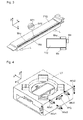
- the second cross member FY2 is shown separately, together with a schematic section through the XZ plane.
- the second cross member FY2 is supported in the Z direction on three aerostatic vacuum-preloaded air bearings L on the granite, and in the Y direction on another (not shown) air bearing on a vertical surface of the granite along the first linear guide FX1.
- This fourth air bearing for the Y direction is also pre-stressed by means of vacuum.
- the total of four air bearings L block four degrees of freedom of the second cross member FY2, so it is an isostatic bearing, by which a force on the movement of the cross member FY2 is avoided on the not perfectly flat granite.
- the other two degrees of freedom (X and rotation about Z) of the second cross member FY2 are controlled by its drives along the linear guides FX1, FX2. Due to the prestressing of all air bearings L by means of vacuum, all the antagonistic forces within the air bearings L compensate each other and no forces are introduced into the second cross member FY2.
- the second cross member FY2 3 scales Mxy, Mz and Mx are arranged.
- the enlarged detail shows a measuring track SP1 and a straightness track SP2.
- the scales Mxy, Mz and Mx on the second cross member FY2 serve as described above for detecting the position of the carriage LY relative to the second cross member FY2, in all six degrees of freedom.
- the scanning heads for scanning the scales Mxy, Mz and Mx are therefore mounted on the carriage LY.
- the spatial position of the carriage LY determines whether one knows the spatial position of the carriage LY, and if one regards this as a rigid body, then the spatial position of each point of the carriage LY (thus eg the Tool Center Points one with the Carriage connected tool or the center of a wafer table) by geometric transformations determine.
- the distance between the two cross members FY1 and FY2 must be set and maintained so accurately that a correct evaluation of the signals of the scanning heads is possible at any time, according to the above-mentioned distance tolerance of about 200 microns.
- the position detection between the carriage LY and the second cross member FY2 is non-contact, e.g. by scanning the scales Mxy, Mz, Mx with light. Therefore, no force acts on the second cross member FY2, which otherwise also rests on a granite (the base G) which is as well insulated as possible due to its air bearing.
- the second cross member FY2 In contrast to the first cross member FY1, during a scanning movement in the Y direction, the second cross member FY2 is not exposed to any process forces or thermal influences which could deform it. If, therefore, the shape of the second cross member is known as accurately as possible by an external calibration, and if its position is determined within an absolute reference frame (which may be given by the base G, for example), the position of the carriage LY relative to this absolute reference frame can also be determined determine.
- the position of the second cross member FY2 (which serves as a movable reference system) for this absolute reference system can be determined by a suitable position measuring system.
- FIG. 5 is indicated how such a position measuring system for the position of the second cross member FY2 can be constructed relative to the base G.
- Three 1Dplus scales M1, M2, M3 are arranged on the base G or fixedly connected to it, so that their graduation tracks cover different directions X, Y, Z.
- these graduation tracks are read, and used the thus determined position values for calculating the spatial position of the second cross member FY relative to the base, again taking into account all six degrees of freedom. Since there are many possibilities here to arrange scanning heads suitable on the second cross member FY2, was dispensed with the representation of a specific arrangement.
- the three scales M1, M2, M3 can also be attached to any other structure that is to be regarded as an absolute reference system for the positioning of the functional element T.
- very delicate optical arrangements for processing or inspecting wafers are often placed on a platform that is not connected to the base of an associated positioning device to avoid deformation of the optics by a vibrating granite. This can cause shifts in the range of a few micrometers between the granite and the platform. In such cases it is better to use this platform as an absolute reference system.
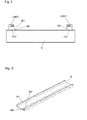
- FIG. 6 That's how it shows FIG. 6 a rail S with a U-profile, in which in turn three 1Dplus - standards M1, M2, M3 are mounted for scanning arranged on the second cross member FY2 scanning heads.
- This dimensionally stable rail which is manufactured with very narrow tolerances, can for example be screwed laterally onto the optical platform, which is arranged above the positioning device in portal construction, and with respect to which the functional element T is to be positioned.
- the scanning heads for scanning the scales M1, M2, M3 must be mounted on the second cross member FY2 in such a way that they can deliver position values in each X position of the second cross member FY2.
Landscapes
- Engineering & Computer Science (AREA)
- Power Engineering (AREA)
- Physics & Mathematics (AREA)
- Microelectronics & Electronic Packaging (AREA)
- Robotics (AREA)
- Mechanical Engineering (AREA)
- Chemical & Material Sciences (AREA)
- Combustion & Propulsion (AREA)
- Electromagnetism (AREA)
- General Physics & Mathematics (AREA)
- Container, Conveyance, Adherence, Positioning, Of Wafer (AREA)
Applications Claiming Priority (1)
| Application Number | Priority Date | Filing Date | Title |
|---|---|---|---|
| DE102014205523.7A DE102014205523A1 (de) | 2014-03-25 | 2014-03-25 | Positioniereinrichtung in Portalbauweise |
Publications (2)
| Publication Number | Publication Date |
|---|---|
| EP2924721A1 true EP2924721A1 (fr) | 2015-09-30 |
| EP2924721B1 EP2924721B1 (fr) | 2020-04-22 |
Family
ID=52146286
Family Applications (1)
| Application Number | Title | Priority Date | Filing Date |
|---|---|---|---|
| EP14199710.6A Active EP2924721B1 (fr) | 2014-03-25 | 2014-12-22 | Dispositif de positionnement à portique |
Country Status (4)
| Country | Link |
|---|---|
| US (1) | US9979262B2 (fr) |
| EP (1) | EP2924721B1 (fr) |
| KR (1) | KR102245707B1 (fr) |
| DE (1) | DE102014205523A1 (fr) |
Cited By (7)
| Publication number | Priority date | Publication date | Assignee | Title |
|---|---|---|---|---|
| DE202017006721U1 (de) | 2017-07-14 | 2018-10-16 | Carl Zeiss Industrielle Messtechnik Gmbh | Luftlagereinrichtung, Halteeinrichtung und Koordinatenmessgerät |
| DE102017212090A1 (de) | 2017-07-14 | 2019-01-17 | Carl Zeiss Industrielle Messtechnik Gmbh | Luftlagereinrichtung, Halteeinrichtung, Koordinatenmessgerät für Verfahren zur Herstellung |
| DE102017212087A1 (de) | 2017-07-14 | 2019-01-17 | Carl Zeiss Industrielle Messtechnik Gmbh | Federelement, Laufwagen, Koordinatenmessgerät und Verfahren zur Herstellung eines Laufwagens |
| DE102017217701A1 (de) | 2017-10-05 | 2019-04-11 | Carl Zeiss Industrielle Messtechnik Gmbh | Luftlagereinrichtung, Verfahren zur Herstellung einer Luftlagereinrichtung, Halteeinrichtung mit Luftlagereinrichtung sowie Koordinatenmessgerät |
| DE102020214851A1 (de) | 2020-11-26 | 2021-11-11 | Carl Zeiss Industrielle Messtechnik Gmbh | Luftlagervorrichtung und für Verfahren zur Herstellung |
| US11408554B2 (en) * | 2017-08-24 | 2022-08-09 | Etel S.A. | Gantry-type positioning device |
| DE102017012475B4 (de) | 2017-10-05 | 2025-03-13 | Carl Zeiss Industrielle Messtechnik Gmbh | Luftlagereinrichtung, Verfahren zur Herstellung einer Luftlagereinrichtung, Halteeinrichtung mit Luftlagereinrichtung sowie Koordinatenmessgerät |
Families Citing this family (4)
| Publication number | Priority date | Publication date | Assignee | Title |
|---|---|---|---|---|
| KR102374227B1 (ko) * | 2017-08-28 | 2022-03-15 | 가부시키가이샤 신가와 | 대상물에 대하여 이동체를 직선 이동시키는 장치 및 방법 |
| CN112234793A (zh) * | 2020-09-18 | 2021-01-15 | 瑞声新能源发展(常州)有限公司科教城分公司 | 一种直线电机 |
| EP4372790A1 (fr) | 2022-11-18 | 2024-05-22 | Dr. Johannes Heidenhain GmbH | Dispositif de positionnement |
| EP4376060A1 (fr) * | 2022-11-22 | 2024-05-29 | Schneeberger Holding AG | Dispositif de positionnement pour positionner un élément mobile |
Citations (7)
| Publication number | Priority date | Publication date | Assignee | Title |
|---|---|---|---|---|
| WO2002067648A1 (fr) | 2001-02-16 | 2002-08-29 | Acd Technologies S.P.A. | Machine-outil destinee au traitement de paquets de cartes a circuits imprimes |
| US20040178327A1 (en) * | 2003-03-10 | 2004-09-16 | Asm Technology Singapore Pte Ltd | Determination of a movable gantry position |
| JP2007109810A (ja) * | 2005-10-12 | 2007-04-26 | Sumitomo Heavy Ind Ltd | ステージ装置及びその制御方法 |
| US20080094592A1 (en) * | 2006-08-31 | 2008-04-24 | Nikon Corporation | Movable body drive method and movable body drive system, pattern formation method and apparatus, exposure method and apparatus, and device manufacturing method |
| EP1975981A1 (fr) * | 2005-12-28 | 2008-10-01 | Nikon Corporation | Procede et dispositif de formation de motif, et procede de fabrication de dispositif |
| DE102008010284A1 (de) * | 2008-02-21 | 2009-08-27 | Dr. Johannes Heidenhain Gmbh | XY-Tisch mit einer Messanordnung zur Positionsbestimmung |
| EP2066996B1 (fr) | 2006-09-20 | 2012-08-29 | Etel S. A.. | Dispositif de positionnement à structure en portique |
Family Cites Families (5)
| Publication number | Priority date | Publication date | Assignee | Title |
|---|---|---|---|---|
| JP2005209670A (ja) * | 2004-01-20 | 2005-08-04 | Canon Inc | 磁気浮上装置 |
| JP2005327993A (ja) * | 2004-05-17 | 2005-11-24 | Canon Inc | 位置決め装置、露光装置及びデバイス製造方法 |
| KR101770082B1 (ko) * | 2006-09-01 | 2017-08-21 | 가부시키가이샤 니콘 | 이동체 구동 방법 및 이동체 구동 시스템, 패턴 형성 방법 및 장치, 노광 방법 및 장치, 디바이스 제조 방법, 그리고 캘리브레이션 방법 |
| US9304412B2 (en) * | 2007-08-24 | 2016-04-05 | Nikon Corporation | Movable body drive method and movable body drive system, pattern formation method and apparatus, exposure method and apparatus, device manufacturing method, and measuring method |
| WO2009098891A1 (fr) * | 2008-02-08 | 2009-08-13 | Nikon Corporation | Système et procédé de mesure de position, dispositif à corps mobile, procédé de pilotage de corps mobile, dispositif et procédé d'exposition, dispositif de formation de motif et procédé de fabrication de dispositifs |
-
2014
- 2014-03-25 DE DE102014205523.7A patent/DE102014205523A1/de not_active Withdrawn
- 2014-12-22 EP EP14199710.6A patent/EP2924721B1/fr active Active
-
2015
- 2015-03-04 KR KR1020150030114A patent/KR102245707B1/ko active Active
- 2015-03-13 US US14/657,650 patent/US9979262B2/en active Active
Patent Citations (7)
| Publication number | Priority date | Publication date | Assignee | Title |
|---|---|---|---|---|
| WO2002067648A1 (fr) | 2001-02-16 | 2002-08-29 | Acd Technologies S.P.A. | Machine-outil destinee au traitement de paquets de cartes a circuits imprimes |
| US20040178327A1 (en) * | 2003-03-10 | 2004-09-16 | Asm Technology Singapore Pte Ltd | Determination of a movable gantry position |
| JP2007109810A (ja) * | 2005-10-12 | 2007-04-26 | Sumitomo Heavy Ind Ltd | ステージ装置及びその制御方法 |
| EP1975981A1 (fr) * | 2005-12-28 | 2008-10-01 | Nikon Corporation | Procede et dispositif de formation de motif, et procede de fabrication de dispositif |
| US20080094592A1 (en) * | 2006-08-31 | 2008-04-24 | Nikon Corporation | Movable body drive method and movable body drive system, pattern formation method and apparatus, exposure method and apparatus, and device manufacturing method |
| EP2066996B1 (fr) | 2006-09-20 | 2012-08-29 | Etel S. A.. | Dispositif de positionnement à structure en portique |
| DE102008010284A1 (de) * | 2008-02-21 | 2009-08-27 | Dr. Johannes Heidenhain Gmbh | XY-Tisch mit einer Messanordnung zur Positionsbestimmung |
Non-Patent Citations (1)
| Title |
|---|
| "Electronics", HEIDENHAIN INFO, vol. 1, 2009 |
Cited By (10)
| Publication number | Priority date | Publication date | Assignee | Title |
|---|---|---|---|---|
| DE202017006721U1 (de) | 2017-07-14 | 2018-10-16 | Carl Zeiss Industrielle Messtechnik Gmbh | Luftlagereinrichtung, Halteeinrichtung und Koordinatenmessgerät |
| DE102017212090A1 (de) | 2017-07-14 | 2019-01-17 | Carl Zeiss Industrielle Messtechnik Gmbh | Luftlagereinrichtung, Halteeinrichtung, Koordinatenmessgerät für Verfahren zur Herstellung |
| DE102017212087A1 (de) | 2017-07-14 | 2019-01-17 | Carl Zeiss Industrielle Messtechnik Gmbh | Federelement, Laufwagen, Koordinatenmessgerät und Verfahren zur Herstellung eines Laufwagens |
| DE102017212087B4 (de) | 2017-07-14 | 2022-06-02 | Carl Zeiss Industrielle Messtechnik Gmbh | Anordnung, Laufwagen, Koordinatenmessgerät und Verfahren zur Herstellung eines Laufwagens |
| DE102017212090B4 (de) | 2017-07-14 | 2022-11-03 | Carl Zeiss Industrielle Messtechnik Gmbh | Luftlagereinrichtung, Halteeinrichtung, Koordinatenmessgerät und Verfahren zur Herstellung |
| US11408554B2 (en) * | 2017-08-24 | 2022-08-09 | Etel S.A. | Gantry-type positioning device |
| DE102017217701A1 (de) | 2017-10-05 | 2019-04-11 | Carl Zeiss Industrielle Messtechnik Gmbh | Luftlagereinrichtung, Verfahren zur Herstellung einer Luftlagereinrichtung, Halteeinrichtung mit Luftlagereinrichtung sowie Koordinatenmessgerät |
| DE102017217701B4 (de) | 2017-10-05 | 2023-03-23 | Carl Zeiss Industrielle Messtechnik Gmbh | Luftlagereinrichtung, Verfahren zur Herstellung einer Luftlagereinrichtung, Halteeinrichtung mit Luftlagereinrichtung sowie Koordinatenmessgerät |
| DE102017012475B4 (de) | 2017-10-05 | 2025-03-13 | Carl Zeiss Industrielle Messtechnik Gmbh | Luftlagereinrichtung, Verfahren zur Herstellung einer Luftlagereinrichtung, Halteeinrichtung mit Luftlagereinrichtung sowie Koordinatenmessgerät |
| DE102020214851A1 (de) | 2020-11-26 | 2021-11-11 | Carl Zeiss Industrielle Messtechnik Gmbh | Luftlagervorrichtung und für Verfahren zur Herstellung |
Also Published As
| Publication number | Publication date |
|---|---|
| US20150280529A1 (en) | 2015-10-01 |
| KR20150111280A (ko) | 2015-10-05 |
| US9979262B2 (en) | 2018-05-22 |
| EP2924721B1 (fr) | 2020-04-22 |
| DE102014205523A1 (de) | 2015-10-01 |
| KR102245707B1 (ko) | 2021-04-29 |
Similar Documents
| Publication | Publication Date | Title |
|---|---|---|
| EP2924721B1 (fr) | Dispositif de positionnement à portique | |
| EP3448140B1 (fr) | Dispositif de positionnement à portique | |
| EP2299472B1 (fr) | Dispositif d'alignement de deux substrats | |
| DE60114397T2 (de) | Verfahren und vorrichtung zur korrektur von abbe fehlern | |
| EP2247915B1 (fr) | Table xy comprenant un système de mesure pour la détermination de position | |
| EP3332261A1 (fr) | Dispositif de positionnement d'un contrôleur parallèle servant à contrôler des cartes de circuits imprimés, et contrôleur parallèle servant à contrôler des cartes de circuits imprimés | |
| EP1880790A1 (fr) | Installation destinée à la structuration de modules solaires | |
| EP0418203A1 (fr) | Appareil de mesure vertical/horizontal et méthode de fonctionnement | |
| EP3011589A1 (fr) | Dispositif et procédé permettant d'orienter des substrats | |
| WO2015082020A1 (fr) | Dispositif et procédé d'alignement de substrats | |
| EP1019669B1 (fr) | Dispositif de detection de la position de deux corps | |
| EP2783791A1 (fr) | Dispositif de positionnement avec portique | |
| DE102011079792A1 (de) | Werkzeugmaschine | |
| EP2679962B1 (fr) | Dispositif de mesure de position | |
| EP2846966B1 (fr) | Centre de transfert destiné à usiner au moins une pièce par enlèvement de matière, comprenant un système de compensation de position | |
| EP2626672B1 (fr) | Agencement à plusieurs unités de balayage d'un dispositif de mesure de position | |
| EP4449486B1 (fr) | Dispositif et procédé de réglage d'un moyen de détection | |
| EP4372790A1 (fr) | Dispositif de positionnement | |
| DE102013201513A1 (de) | Anordnung und Verfahren zur Positionierung eines Bearbeitungswerkzeuges gegenüber einem Werkstück | |
| DE102012200220A1 (de) | Verfahren zum Kalibrieren eines aktiv magnetgelagerten Roboters | |
| DE102019127499B4 (de) | Koordinatenmessgerät und Steuerungsverfahren eines Koordinatenmessgerätes | |
| DE102018123933B4 (de) | Positioniervorrichtung und Mikrotom | |
| DE10329931A1 (de) | Planarer Direktantrieb mit einem Positionsmesssystem | |
| WO2006027317A1 (fr) | Dispositif de guidage pour guider un organe mobile d'une machine | |
| EP2633547B1 (fr) | Procédé de détermination de la position d'un axe de rotation |
Legal Events
| Date | Code | Title | Description |
|---|---|---|---|
| PUAI | Public reference made under article 153(3) epc to a published international application that has entered the european phase |
Free format text: ORIGINAL CODE: 0009012 |
|
| AK | Designated contracting states |
Kind code of ref document: A1 Designated state(s): AL AT BE BG CH CY CZ DE DK EE ES FI FR GB GR HR HU IE IS IT LI LT LU LV MC MK MT NL NO PL PT RO RS SE SI SK SM TR |
|
| AX | Request for extension of the european patent |
Extension state: BA ME |
|
| 17P | Request for examination filed |
Effective date: 20160330 |
|
| RBV | Designated contracting states (corrected) |
Designated state(s): AL AT BE BG CH CY CZ DE DK EE ES FI FR GB GR HR HU IE IS IT LI LT LU LV MC MK MT NL NO PL PT RO RS SE SI SK SM TR |
|
| STAA | Information on the status of an ep patent application or granted ep patent |
Free format text: STATUS: EXAMINATION IS IN PROGRESS |
|
| 17Q | First examination report despatched |
Effective date: 20190411 |
|
| GRAP | Despatch of communication of intention to grant a patent |
Free format text: ORIGINAL CODE: EPIDOSNIGR1 |
|
| STAA | Information on the status of an ep patent application or granted ep patent |
Free format text: STATUS: GRANT OF PATENT IS INTENDED |
|
| INTG | Intention to grant announced |
Effective date: 20191118 |
|
| GRAS | Grant fee paid |
Free format text: ORIGINAL CODE: EPIDOSNIGR3 |
|
| GRAA | (expected) grant |
Free format text: ORIGINAL CODE: 0009210 |
|
| STAA | Information on the status of an ep patent application or granted ep patent |
Free format text: STATUS: THE PATENT HAS BEEN GRANTED |
|
| AK | Designated contracting states |
Kind code of ref document: B1 Designated state(s): AL AT BE BG CH CY CZ DE DK EE ES FI FR GB GR HR HU IE IS IT LI LT LU LV MC MK MT NL NO PL PT RO RS SE SI SK SM TR |
|
| REG | Reference to a national code |
Ref country code: GB Ref legal event code: FG4D Free format text: NOT ENGLISH |
|
| REG | Reference to a national code |
Ref country code: CH Ref legal event code: EP |
|
| REG | Reference to a national code |
Ref country code: DE Ref legal event code: R096 Ref document number: 502014014031 Country of ref document: DE |
|
| REG | Reference to a national code |
Ref country code: IE Ref legal event code: FG4D Free format text: LANGUAGE OF EP DOCUMENT: GERMAN |
|
| REG | Reference to a national code |
Ref country code: AT Ref legal event code: REF Ref document number: 1261253 Country of ref document: AT Kind code of ref document: T Effective date: 20200515 |
|
| REG | Reference to a national code |
Ref country code: NL Ref legal event code: FP |
|
| REG | Reference to a national code |
Ref country code: CH Ref legal event code: NV Representative=s name: ICB INGENIEURS CONSEILS EN BREVETS SA, CH |
|
| REG | Reference to a national code |
Ref country code: LT Ref legal event code: MG4D |
|
| PG25 | Lapsed in a contracting state [announced via postgrant information from national office to epo] |
Ref country code: GR Free format text: LAPSE BECAUSE OF FAILURE TO SUBMIT A TRANSLATION OF THE DESCRIPTION OR TO PAY THE FEE WITHIN THE PRESCRIBED TIME-LIMIT Effective date: 20200723 Ref country code: PT Free format text: LAPSE BECAUSE OF FAILURE TO SUBMIT A TRANSLATION OF THE DESCRIPTION OR TO PAY THE FEE WITHIN THE PRESCRIBED TIME-LIMIT Effective date: 20200824 Ref country code: LT Free format text: LAPSE BECAUSE OF FAILURE TO SUBMIT A TRANSLATION OF THE DESCRIPTION OR TO PAY THE FEE WITHIN THE PRESCRIBED TIME-LIMIT Effective date: 20200422 Ref country code: FI Free format text: LAPSE BECAUSE OF FAILURE TO SUBMIT A TRANSLATION OF THE DESCRIPTION OR TO PAY THE FEE WITHIN THE PRESCRIBED TIME-LIMIT Effective date: 20200422 Ref country code: IS Free format text: LAPSE BECAUSE OF FAILURE TO SUBMIT A TRANSLATION OF THE DESCRIPTION OR TO PAY THE FEE WITHIN THE PRESCRIBED TIME-LIMIT Effective date: 20200822 Ref country code: NO Free format text: LAPSE BECAUSE OF FAILURE TO SUBMIT A TRANSLATION OF THE DESCRIPTION OR TO PAY THE FEE WITHIN THE PRESCRIBED TIME-LIMIT Effective date: 20200722 Ref country code: SE Free format text: LAPSE BECAUSE OF FAILURE TO SUBMIT A TRANSLATION OF THE DESCRIPTION OR TO PAY THE FEE WITHIN THE PRESCRIBED TIME-LIMIT Effective date: 20200422 |
|
| PG25 | Lapsed in a contracting state [announced via postgrant information from national office to epo] |
Ref country code: HR Free format text: LAPSE BECAUSE OF FAILURE TO SUBMIT A TRANSLATION OF THE DESCRIPTION OR TO PAY THE FEE WITHIN THE PRESCRIBED TIME-LIMIT Effective date: 20200422 Ref country code: LV Free format text: LAPSE BECAUSE OF FAILURE TO SUBMIT A TRANSLATION OF THE DESCRIPTION OR TO PAY THE FEE WITHIN THE PRESCRIBED TIME-LIMIT Effective date: 20200422 Ref country code: RS Free format text: LAPSE BECAUSE OF FAILURE TO SUBMIT A TRANSLATION OF THE DESCRIPTION OR TO PAY THE FEE WITHIN THE PRESCRIBED TIME-LIMIT Effective date: 20200422 Ref country code: BG Free format text: LAPSE BECAUSE OF FAILURE TO SUBMIT A TRANSLATION OF THE DESCRIPTION OR TO PAY THE FEE WITHIN THE PRESCRIBED TIME-LIMIT Effective date: 20200722 |
|
| PG25 | Lapsed in a contracting state [announced via postgrant information from national office to epo] |
Ref country code: AL Free format text: LAPSE BECAUSE OF FAILURE TO SUBMIT A TRANSLATION OF THE DESCRIPTION OR TO PAY THE FEE WITHIN THE PRESCRIBED TIME-LIMIT Effective date: 20200422 |
|
| REG | Reference to a national code |
Ref country code: DE Ref legal event code: R097 Ref document number: 502014014031 Country of ref document: DE |
|
| PG25 | Lapsed in a contracting state [announced via postgrant information from national office to epo] |
Ref country code: ES Free format text: LAPSE BECAUSE OF FAILURE TO SUBMIT A TRANSLATION OF THE DESCRIPTION OR TO PAY THE FEE WITHIN THE PRESCRIBED TIME-LIMIT Effective date: 20200422 Ref country code: CZ Free format text: LAPSE BECAUSE OF FAILURE TO SUBMIT A TRANSLATION OF THE DESCRIPTION OR TO PAY THE FEE WITHIN THE PRESCRIBED TIME-LIMIT Effective date: 20200422 Ref country code: RO Free format text: LAPSE BECAUSE OF FAILURE TO SUBMIT A TRANSLATION OF THE DESCRIPTION OR TO PAY THE FEE WITHIN THE PRESCRIBED TIME-LIMIT Effective date: 20200422 Ref country code: DK Free format text: LAPSE BECAUSE OF FAILURE TO SUBMIT A TRANSLATION OF THE DESCRIPTION OR TO PAY THE FEE WITHIN THE PRESCRIBED TIME-LIMIT Effective date: 20200422 Ref country code: IT Free format text: LAPSE BECAUSE OF FAILURE TO SUBMIT A TRANSLATION OF THE DESCRIPTION OR TO PAY THE FEE WITHIN THE PRESCRIBED TIME-LIMIT Effective date: 20200422 Ref country code: SM Free format text: LAPSE BECAUSE OF FAILURE TO SUBMIT A TRANSLATION OF THE DESCRIPTION OR TO PAY THE FEE WITHIN THE PRESCRIBED TIME-LIMIT Effective date: 20200422 Ref country code: EE Free format text: LAPSE BECAUSE OF FAILURE TO SUBMIT A TRANSLATION OF THE DESCRIPTION OR TO PAY THE FEE WITHIN THE PRESCRIBED TIME-LIMIT Effective date: 20200422 |
|
| PG25 | Lapsed in a contracting state [announced via postgrant information from national office to epo] |
Ref country code: SK Free format text: LAPSE BECAUSE OF FAILURE TO SUBMIT A TRANSLATION OF THE DESCRIPTION OR TO PAY THE FEE WITHIN THE PRESCRIBED TIME-LIMIT Effective date: 20200422 Ref country code: PL Free format text: LAPSE BECAUSE OF FAILURE TO SUBMIT A TRANSLATION OF THE DESCRIPTION OR TO PAY THE FEE WITHIN THE PRESCRIBED TIME-LIMIT Effective date: 20200422 |
|
| PLBE | No opposition filed within time limit |
Free format text: ORIGINAL CODE: 0009261 |
|
| STAA | Information on the status of an ep patent application or granted ep patent |
Free format text: STATUS: NO OPPOSITION FILED WITHIN TIME LIMIT |
|
| 26N | No opposition filed |
Effective date: 20210125 |
|
| PG25 | Lapsed in a contracting state [announced via postgrant information from national office to epo] |
Ref country code: SI Free format text: LAPSE BECAUSE OF FAILURE TO SUBMIT A TRANSLATION OF THE DESCRIPTION OR TO PAY THE FEE WITHIN THE PRESCRIBED TIME-LIMIT Effective date: 20200422 |
|
| GBPC | Gb: european patent ceased through non-payment of renewal fee |
Effective date: 20201222 |
|
| PG25 | Lapsed in a contracting state [announced via postgrant information from national office to epo] |
Ref country code: MC Free format text: LAPSE BECAUSE OF FAILURE TO SUBMIT A TRANSLATION OF THE DESCRIPTION OR TO PAY THE FEE WITHIN THE PRESCRIBED TIME-LIMIT Effective date: 20200422 |
|
| REG | Reference to a national code |
Ref country code: BE Ref legal event code: MM Effective date: 20201231 |
|
| PG25 | Lapsed in a contracting state [announced via postgrant information from national office to epo] |
Ref country code: LU Free format text: LAPSE BECAUSE OF NON-PAYMENT OF DUE FEES Effective date: 20201222 Ref country code: IE Free format text: LAPSE BECAUSE OF NON-PAYMENT OF DUE FEES Effective date: 20201222 |
|
| PG25 | Lapsed in a contracting state [announced via postgrant information from national office to epo] |
Ref country code: GB Free format text: LAPSE BECAUSE OF NON-PAYMENT OF DUE FEES Effective date: 20201222 |
|
| PG25 | Lapsed in a contracting state [announced via postgrant information from national office to epo] |
Ref country code: TR Free format text: LAPSE BECAUSE OF FAILURE TO SUBMIT A TRANSLATION OF THE DESCRIPTION OR TO PAY THE FEE WITHIN THE PRESCRIBED TIME-LIMIT Effective date: 20200422 Ref country code: MT Free format text: LAPSE BECAUSE OF FAILURE TO SUBMIT A TRANSLATION OF THE DESCRIPTION OR TO PAY THE FEE WITHIN THE PRESCRIBED TIME-LIMIT Effective date: 20200422 Ref country code: CY Free format text: LAPSE BECAUSE OF FAILURE TO SUBMIT A TRANSLATION OF THE DESCRIPTION OR TO PAY THE FEE WITHIN THE PRESCRIBED TIME-LIMIT Effective date: 20200422 |
|
| PG25 | Lapsed in a contracting state [announced via postgrant information from national office to epo] |
Ref country code: MK Free format text: LAPSE BECAUSE OF FAILURE TO SUBMIT A TRANSLATION OF THE DESCRIPTION OR TO PAY THE FEE WITHIN THE PRESCRIBED TIME-LIMIT Effective date: 20200422 |
|
| PG25 | Lapsed in a contracting state [announced via postgrant information from national office to epo] |
Ref country code: BE Free format text: LAPSE BECAUSE OF NON-PAYMENT OF DUE FEES Effective date: 20201231 |
|
| PG25 | Lapsed in a contracting state [announced via postgrant information from national office to epo] |
Ref country code: IS Free format text: LAPSE BECAUSE OF NON-PAYMENT OF DUE FEES Effective date: 20200822 |
|
| REG | Reference to a national code |
Ref country code: DE Ref legal event code: R079 Ref document number: 502014014031 Country of ref document: DE Free format text: PREVIOUS MAIN CLASS: H01L0021680000 Ipc: H10P0072500000 |
|
| REG | Reference to a national code |
Ref country code: CH Ref legal event code: U11 Free format text: ST27 STATUS EVENT CODE: U-0-0-U10-U11 (AS PROVIDED BY THE NATIONAL OFFICE) Effective date: 20260101 |
|
| PGFP | Annual fee paid to national office [announced via postgrant information from national office to epo] |
Ref country code: DE Payment date: 20251211 Year of fee payment: 12 |
|
| REG | Reference to a national code |
Ref country code: CH Ref legal event code: R17 Free format text: ST27 STATUS EVENT CODE: U-0-0-R10-R17 (AS PROVIDED BY THE NATIONAL OFFICE) Effective date: 20260108 |
|
| PGFP | Annual fee paid to national office [announced via postgrant information from national office to epo] |
Ref country code: AT Payment date: 20251222 Year of fee payment: 12 |
|
| PGFP | Annual fee paid to national office [announced via postgrant information from national office to epo] |
Ref country code: FR Payment date: 20251223 Year of fee payment: 12 Ref country code: NL Payment date: 20251219 Year of fee payment: 12 |
|
| PGFP | Annual fee paid to national office [announced via postgrant information from national office to epo] |
Ref country code: CH Payment date: 20260101 Year of fee payment: 12 |