EP2924977B1 - Module de lentille et dispositif de photographie portable - Google Patents
Module de lentille et dispositif de photographie portable Download PDFInfo
- Publication number
- EP2924977B1 EP2924977B1 EP13866872.8A EP13866872A EP2924977B1 EP 2924977 B1 EP2924977 B1 EP 2924977B1 EP 13866872 A EP13866872 A EP 13866872A EP 2924977 B1 EP2924977 B1 EP 2924977B1
- Authority
- EP
- European Patent Office
- Prior art keywords
- photography
- led
- light
- control means
- state
- Prior art date
- Legal status (The legal status is an assumption and is not a legal conclusion. Google has not performed a legal analysis and makes no representation as to the accuracy of the status listed.)
- Not-in-force
Links
Images


Classifications
-
- G—PHYSICS
- G03—PHOTOGRAPHY; CINEMATOGRAPHY; ANALOGOUS TECHNIQUES USING WAVES OTHER THAN OPTICAL WAVES; ELECTROGRAPHY; HOLOGRAPHY
- G03B—APPARATUS OR ARRANGEMENTS FOR TAKING PHOTOGRAPHS OR FOR PROJECTING OR VIEWING THEM; APPARATUS OR ARRANGEMENTS EMPLOYING ANALOGOUS TECHNIQUES USING WAVES OTHER THAN OPTICAL WAVES; ACCESSORIES THEREFOR
- G03B15/00—Special procedures for taking photographs; Apparatus therefor
- G03B15/02—Illuminating scene
- G03B15/03—Combinations of cameras with lighting apparatus; Flash units
- G03B15/05—Combinations of cameras with electronic flash apparatus; Electronic flash units
-
- A—HUMAN NECESSITIES
- A61—MEDICAL OR VETERINARY SCIENCE; HYGIENE
- A61B—DIAGNOSIS; SURGERY; IDENTIFICATION
- A61B5/00—Measuring for diagnostic purposes; Identification of persons
-
- F—MECHANICAL ENGINEERING; LIGHTING; HEATING; WEAPONS; BLASTING
- F21—LIGHTING
- F21L—LIGHTING DEVICES OR SYSTEMS THEREOF, BEING PORTABLE OR SPECIALLY ADAPTED FOR TRANSPORTATION
- F21L4/00—Electric lighting devices with self-contained electric batteries or cells
- F21L4/02—Electric lighting devices with self-contained electric batteries or cells characterised by the provision of two or more light sources
-
- F—MECHANICAL ENGINEERING; LIGHTING; HEATING; WEAPONS; BLASTING
- F21—LIGHTING
- F21V—FUNCTIONAL FEATURES OR DETAILS OF LIGHTING DEVICES OR SYSTEMS THEREOF; STRUCTURAL COMBINATIONS OF LIGHTING DEVICES WITH OTHER ARTICLES, NOT OTHERWISE PROVIDED FOR
- F21V23/00—Arrangement of electric circuit elements in or on lighting devices
- F21V23/04—Arrangement of electric circuit elements in or on lighting devices the elements being switches
- F21V23/0414—Arrangement of electric circuit elements in or on lighting devices the elements being switches specially adapted to be used with portable lighting devices
-
- F—MECHANICAL ENGINEERING; LIGHTING; HEATING; WEAPONS; BLASTING
- F21—LIGHTING
- F21V—FUNCTIONAL FEATURES OR DETAILS OF LIGHTING DEVICES OR SYSTEMS THEREOF; STRUCTURAL COMBINATIONS OF LIGHTING DEVICES WITH OTHER ARTICLES, NOT OTHERWISE PROVIDED FOR
- F21V23/00—Arrangement of electric circuit elements in or on lighting devices
- F21V23/04—Arrangement of electric circuit elements in or on lighting devices the elements being switches
- F21V23/0442—Arrangement of electric circuit elements in or on lighting devices the elements being switches activated by means of a sensor, e.g. motion or photodetectors
- F21V23/0457—Arrangement of electric circuit elements in or on lighting devices the elements being switches activated by means of a sensor, e.g. motion or photodetectors the sensor sensing the operating status of the lighting device, e.g. to detect failure of a light source or to provide feedback to the device
-
- G—PHYSICS
- G02—OPTICS
- G02B—OPTICAL ELEMENTS, SYSTEMS OR APPARATUS
- G02B13/00—Optical objectives specially designed for the purposes specified below
- G02B13/24—Optical objectives specially designed for the purposes specified below for reproducing or copying at short object distances
-
- G—PHYSICS
- G03—PHOTOGRAPHY; CINEMATOGRAPHY; ANALOGOUS TECHNIQUES USING WAVES OTHER THAN OPTICAL WAVES; ELECTROGRAPHY; HOLOGRAPHY
- G03B—APPARATUS OR ARRANGEMENTS FOR TAKING PHOTOGRAPHS OR FOR PROJECTING OR VIEWING THEM; APPARATUS OR ARRANGEMENTS EMPLOYING ANALOGOUS TECHNIQUES USING WAVES OTHER THAN OPTICAL WAVES; ACCESSORIES THEREFOR
- G03B17/00—Details of cameras or camera bodies; Accessories therefor
- G03B17/02—Bodies
- G03B17/12—Bodies with means for supporting objectives, supplementary lenses, filters, masks, or turrets
- G03B17/14—Bodies with means for supporting objectives, supplementary lenses, filters, masks, or turrets interchangeably
-
- G—PHYSICS
- G03—PHOTOGRAPHY; CINEMATOGRAPHY; ANALOGOUS TECHNIQUES USING WAVES OTHER THAN OPTICAL WAVES; ELECTROGRAPHY; HOLOGRAPHY
- G03B—APPARATUS OR ARRANGEMENTS FOR TAKING PHOTOGRAPHS OR FOR PROJECTING OR VIEWING THEM; APPARATUS OR ARRANGEMENTS EMPLOYING ANALOGOUS TECHNIQUES USING WAVES OTHER THAN OPTICAL WAVES; ACCESSORIES THEREFOR
- G03B17/00—Details of cameras or camera bodies; Accessories therefor
- G03B17/56—Accessories
- G03B17/565—Optical accessories, e.g. converters for close-up photography, tele-convertors, wide-angle convertors
-
- H—ELECTRICITY
- H04—ELECTRIC COMMUNICATION TECHNIQUE
- H04N—PICTORIAL COMMUNICATION, e.g. TELEVISION
- H04N23/00—Cameras or camera modules comprising electronic image sensors; Control thereof
- H04N23/50—Constructional details
- H04N23/55—Optical parts specially adapted for electronic image sensors; Mounting thereof
-
- H—ELECTRICITY
- H04—ELECTRIC COMMUNICATION TECHNIQUE
- H04N—PICTORIAL COMMUNICATION, e.g. TELEVISION
- H04N23/00—Cameras or camera modules comprising electronic image sensors; Control thereof
- H04N23/56—Cameras or camera modules comprising electronic image sensors; Control thereof provided with illuminating means
-
- H—ELECTRICITY
- H04—ELECTRIC COMMUNICATION TECHNIQUE
- H04N—PICTORIAL COMMUNICATION, e.g. TELEVISION
- H04N23/00—Cameras or camera modules comprising electronic image sensors; Control thereof
- H04N23/57—Mechanical or electrical details of cameras or camera modules specially adapted for being embedded in other devices
-
- H—ELECTRICITY
- H04—ELECTRIC COMMUNICATION TECHNIQUE
- H04N—PICTORIAL COMMUNICATION, e.g. TELEVISION
- H04N23/00—Cameras or camera modules comprising electronic image sensors; Control thereof
- H04N23/60—Control of cameras or camera modules
- H04N23/63—Control of cameras or camera modules by using electronic viewfinders
- H04N23/631—Graphical user interfaces [GUI] specially adapted for controlling image capture or setting capture parameters
- H04N23/632—Graphical user interfaces [GUI] specially adapted for controlling image capture or setting capture parameters for displaying or modifying preview images prior to image capturing, e.g. variety of image resolutions or capturing parameters
-
- H—ELECTRICITY
- H04—ELECTRIC COMMUNICATION TECHNIQUE
- H04N—PICTORIAL COMMUNICATION, e.g. TELEVISION
- H04N23/00—Cameras or camera modules comprising electronic image sensors; Control thereof
- H04N23/60—Control of cameras or camera modules
- H04N23/65—Control of camera operation in relation to power supply
- H04N23/651—Control of camera operation in relation to power supply for reducing power consumption by affecting camera operations, e.g. sleep mode, hibernation mode or power off of selective parts of the camera
-
- H—ELECTRICITY
- H04—ELECTRIC COMMUNICATION TECHNIQUE
- H04N—PICTORIAL COMMUNICATION, e.g. TELEVISION
- H04N23/00—Cameras or camera modules comprising electronic image sensors; Control thereof
- H04N23/70—Circuitry for compensating brightness variation in the scene
- H04N23/75—Circuitry for compensating brightness variation in the scene by influencing optical camera components
-
- A—HUMAN NECESSITIES
- A61—MEDICAL OR VETERINARY SCIENCE; HYGIENE
- A61B—DIAGNOSIS; SURGERY; IDENTIFICATION
- A61B2560/00—Constructional details of operational features of apparatus; Accessories for medical measuring apparatus
- A61B2560/04—Constructional details of apparatus
- A61B2560/0443—Modular apparatus
-
- A—HUMAN NECESSITIES
- A61—MEDICAL OR VETERINARY SCIENCE; HYGIENE
- A61B—DIAGNOSIS; SURGERY; IDENTIFICATION
- A61B5/00—Measuring for diagnostic purposes; Identification of persons
- A61B5/0059—Measuring for diagnostic purposes; Identification of persons using light, e.g. diagnosis by transillumination, diascopy, fluorescence
- A61B5/0075—Measuring for diagnostic purposes; Identification of persons using light, e.g. diagnosis by transillumination, diascopy, fluorescence by spectroscopy, i.e. measuring spectra, e.g. Raman spectroscopy, infrared absorption spectroscopy
-
- A—HUMAN NECESSITIES
- A61—MEDICAL OR VETERINARY SCIENCE; HYGIENE
- A61B—DIAGNOSIS; SURGERY; IDENTIFICATION
- A61B5/00—Measuring for diagnostic purposes; Identification of persons
- A61B5/44—Detecting, measuring or recording for evaluating the integumentary system, e.g. skin, hair or nails
- A61B5/441—Skin evaluation, e.g. for skin disorder diagnosis
-
- G—PHYSICS
- G03—PHOTOGRAPHY; CINEMATOGRAPHY; ANALOGOUS TECHNIQUES USING WAVES OTHER THAN OPTICAL WAVES; ELECTROGRAPHY; HOLOGRAPHY
- G03B—APPARATUS OR ARRANGEMENTS FOR TAKING PHOTOGRAPHS OR FOR PROJECTING OR VIEWING THEM; APPARATUS OR ARRANGEMENTS EMPLOYING ANALOGOUS TECHNIQUES USING WAVES OTHER THAN OPTICAL WAVES; ACCESSORIES THEREFOR
- G03B2215/00—Special procedures for taking photographs; Apparatus therefor
- G03B2215/05—Combinations of cameras with electronic flash units
- G03B2215/0564—Combinations of cameras with electronic flash units characterised by the type of light source
- G03B2215/0567—Solid-state light source, e.g. LED, laser
-
- G—PHYSICS
- G03—PHOTOGRAPHY; CINEMATOGRAPHY; ANALOGOUS TECHNIQUES USING WAVES OTHER THAN OPTICAL WAVES; ELECTROGRAPHY; HOLOGRAPHY
- G03B—APPARATUS OR ARRANGEMENTS FOR TAKING PHOTOGRAPHS OR FOR PROJECTING OR VIEWING THEM; APPARATUS OR ARRANGEMENTS EMPLOYING ANALOGOUS TECHNIQUES USING WAVES OTHER THAN OPTICAL WAVES; ACCESSORIES THEREFOR
- G03B2215/00—Special procedures for taking photographs; Apparatus therefor
- G03B2215/05—Combinations of cameras with electronic flash units
- G03B2215/0589—Diffusors, filters or refraction means
Definitions
- the present invention relates to a lens module that is removably installed to a portable terminal including a camera, and also relates to a portable photography device including such a lens module and the portable terminal.
- EP 1 707 928 A1 discloses an image processing system which is applied to dentistry, for example, and performs photography of the teeth of a patient while causing a plurality of illumination light LEDs of different wavelength to emit light by means of a photography device when producing a crown repair or denture of the patient, whereby image data are acquired.
- JP 2012-8283 A for example, a conversion lens installed on an electronic device including a portable camera, such as a portable phone (including a smartphone) with camera or a tablet-type electronic device with camera, has been known.
- a portable camera such as a portable phone (including a smartphone) with camera or a tablet-type electronic device with camera
- the focal length of the lens can be changed to the wide angle side or the telescope side even when the lens of the portable electronic device is a fixed focus lens.
- a lens having a close-up function may be used as the conversion lens to allow macro photography.
- a camera for skin for photographing skin of a face in a magnified manner to analyze the state of the skin has also been known.
- a conversion lens having a function of the camera for skin, such as an object magnification and close-up function, added to the camera of the portable phone or the like has also been known. In this case, it can be realized easily to send a photographed image of the skin by mail or the like to the company who analyzes the skin image and receive a result of the skin analysis by mail or the like.
- the conversion lens that allows the portable phone to have the photographing function of the skin is configured to approach to the skin to take a close-up photo (macro photography).
- the portable phone or smartphone often includes a flash apparatus that uses an LED as a light source to provide illumination during photography with a camera.
- the LED used in this flash apparatus is typically set to illuminate an object located at about 1 m apart from the camera with a proper quantity of light.
- the LED of the flash apparatus comes too close to the object, and interrupts uniform illumination of the skin as the object or otherwise causes overexposure of the photographed image due to extremely bright illumination. It may be possible to photograph the skin with natural light, or indoor illumination without using the flash apparatus, but such lighting is likely to be largely changed according the situation.
- a flash apparatus suitable for macro photography in the conversion lens.
- a built-in battery is provided in the flash apparatus as a power source of the LED which is used as a light source of the flash apparatus.
- a power switch is also provided such that a user turns on the power switch at the start of the photographing operation to emit light and turns off the power switch at the end of the photographing operation to extinguish the light.
- the flash apparatus When the flash apparatus is used in this manner, the flash apparatus continues to be turned on for relatively long time, instead of emitting light only instantly. This causes an increase of power consumption compared to the case where the light is turned on momentarily as in the typical flash apparatus. As a result, a large size and large capacity battery may be required or replacement timing of the battery may be earlier.
- an illumination mode texture mode
- an illumination mode blot mode
- the present invention has been made in view of the above problems, and an object of the present invention is to provide a lens module installed on a portable terminal with camera, the lens module capable of carrying out multiple types of photography when photographing an object such as skin, and appropriately carrying out on/off control of a light source during photography, and also provide a portable photography device capable of reliably carrying out photography with a camera in a portable terminal when the light source is turned on.
- a lens module is removably installed on a portable terminal which includes a camera.
- the lens module includes multiple types of light sources having different wavelengths to emit light to an object, a conversion lens that collects reflection light emitted from the light sources and reflected on the object, and light source control means that carries out on/off control of the multiple types of light sources.
- multiple types of light sources having different wavelengths to emit light to the object such as skin are provided to facilitate carrying out several types of photography.
- the light source control means By carrying out the on/off control of the light sources by the light source control means, it is able to appropriately carry out the on/off control of the light sources during the photography.
- the portable photography device of the present invention includes a portable terminal with camera and the lens module according to the present invention.
- the portable terminal includes light on/off detection means that detects an on/off state of each of the multiple types of light sources, photography control means that controls photography by the camera when the off state of each of the light sources is detected, and display control means that associates a photographed image taken by the camera according to the control by the photography control means with the types of the light sources and displays the photographed image on the screen of the portable terminal.
- the photography control means can carry out photography by the camera, while causing the camera to enter a standby state until turning off of the each of multiple types of light sources is detected. As a result, it is possible to photograph the object by the camera using the multiple types of light sources.
- the photographed image taken by the camera is associated with the type of the light source and displayed on the screen of the portable terminal by the display control means, a user can easily confirm the type of the photographed image displayed on the screen.
- the display control means may associate the photographed image taken by the camera according to the wavelength component with the light source and display the photographed image on the screen of the portable terminal.
- the photographed image is thus associated with the light source according to the wavelength component of the photographed image and displayed on the screen. It is not necessary to associate the photographed image with the type of the light source during photography by the camera. Accordingly, there is an advantage that an allowed deviation from a prescribed value of the light source can be increased to suppress the cost of the light source.
- the light source such as an LED
- the light source to be installed on the lens module needs to be a light source having a smaller deviation from the prescribed value both in the light source for texture photographing and the light source for blot photographing.
- a light source having a wavelength closer to the prescribed value should be selected and used. This leads to a cost increase of the light source like an LED, but, according to the above structure, the cost of the light source can be decreased by increasing the allowed deviation from the prescribed value of the light source.
- the light source control means of the lens module may repeatedly controls the multiple types of light sources to be turned on successively for a predetermined time period and, after all of the multiple types of light sources have been turned on, turn off all the light sources for a predetermined time period.
- the photography control means controls photography by the camera. Subsequently, the photography control means may control the photography by the camera at predetermined time intervals in synchronization with turning on of the multiple types of light sources.
- the light source control means repeatedly controls the multiple types of light sources to be turned on successively for a predetermined time period and, after all of the multiple types of light sources have been detected, turn on all the light sources for a predetermined time period.
- the photography control means controls photography by the camera. Subsequently, the photography control means controls the photography by the camera at predetermined time intervals in synchronization with the turning on of the multiple types of light sources.
- the light source control means of the lens module may control the multiple types of light sources to be turned on and turned off successively and repeatedly at predetermined time intervals.
- the light on/off detection means may detect which light source is on by detecting the wavelength of light of each of the light sources.
- the photography control means may control photography by the camera.
- controlling photography by the camera refers to releasing the shutter of the camera by the photography control means.
- the photography control means controls photography by the camera. Accordingly, it is possible to reliably carry out photography by the camera of the portable terminal using the multiple types of light sources.
- the light source control means of the lens module may repeatedly controls the multiple types of light sources to be turned on successively for a predetermined time period and, after all of the multiple types of light sources have been turned on, all the light sources are turned off for a predetermined time period.
- the light source control means may then repeatedly control that, when the light on/off detection means detects the on state of the light source first time after the off state of all the light sources has been detected, the photography control means controls photography by the camera, and when the light on/off detection means detects the off state of all the light sources and then detects which light source is turned on according to the wavelength, the photography control means controls photography by the camera.
- the light source control means repeatedly control the multiple types of light sources to be turned on successively for a predetermined time period and, after all of the multiple types of light sources have been turned on, all the light sources are turned off for a predetermined time period.
- the light source control means then repeatedly controls that, when the light on/off detection means detects the on state of the light source first time after all the light sources have been turned off, the photography control means controls photography by the camera, and when the light on/off detection means detects the off state of all the light sources and then detects which light source is turned on according to the wavelength, the photography control means controls photography by the camera. Accordingly, it is possible to reliably carry out photography by the camera of the portable terminal using the multiple types of light sources, while carrying out photography using each light source at appropriate timing.
- the lens module of the present invention includes transmission/reception means that receives a light-source turn-on instruction signal and a light-source turn-off instruction signal from the portable terminal, while transmitting a light-source turn-on reporting signal and a light-source turn-off reporting signal to the portable terminal.
- the light source control means may turn on the light source and cause the transmission/reception means to transmit the light-source turn-on reporting signal to the portable terminal.
- the light source control means may turn off the light source and cause the transmission/reception means to transmit a light-source turn-off reporting signal to the portable terminal.
- the light source control means turns on the light source upon receipt of the light-source turn-on instruction signal from the portable terminal, while causing the transmission/reception means to transmit the light-source turn-on reporting signal to the portable terminal. Accordingly, it is possible to turn on the light source at appropriate timing according to the photography by the camera.
- the light source control means turns off the light source, while causing the transmission/reception means to transmit the light-source turn-off reporting signal to the portable terminal. Accordingly, it is possible to turn off the light source at appropriate timing according to ending of the photography by the camera.
- the portable photography device of the present invention includes a portable terminal with camera and the lens module.
- the portable terminal includes: transmission/reception means on the terminal side that receives a light-source turn-on reporting signal and a light-source turn-off reporting signal from the transmission/reception means of the lens module, while transmitting a light-source turn-on instruction signal and a light-source turn-off instruction signal to the lens module; control means; and display control means.
- the control means carries out photography by the camera when receiving the light-source turn-on reporting signal from the lens module via the transmission/reception means and the transmission/reception means on the terminal side.
- the control means transmits the light-source turn-off instruction signal to the lens module via the transmission/reception means on the terminal side and the transmission/reception means.
- the control means transmits the light-source turn-on instruction signal to the lens module via the transmission/reception means and the transmission/reception means on the terminal side.
- the control means associates the photographed image taken by the camera with the type of the light source and displays the photographed image on the screen of the portable terminal.
- the control means of the portable terminal carries out photography by the camera when the light-source turn-on reporting signal is received from the lens module via the transmission/reception means and the transmission/reception means on the terminal side. It is, therefore, possible to reliably photograph the object with the camera.
- the light-source turn-off instruction signal is transmitted to the lens module via the transmission/reception means of the portable terminal and the transmission/reception means. It is possible, therefore, to reliably turn off the light source to prevent consumption of the battery.
- the photographed image taken with the camera is associated with the type of the light source and displayed on the screen of the portable terminal by the display control means. Accordingly, the user can easily recognize the type of the photographed image displayed on the screen.
- the lens module of the present invention it is possible to carry out multiple types of photography when photographing the object such as skin, while appropriately controlling turning on/off of the light source during shooting.
- the portable photography device of the present invention it is possible to reliably carry out photography with the camera of the portable terminal when the light source is turned on.
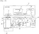
- a portable photography device of the present embodiment includes a smartphone 1 (illustrated in Figs. 1 to 7A ) that is a portable electronic device (portable terminal) with a digital camera (a camera 2 including an image capturing device illustrated in Fig. 2 ), and a lens module 10 including a conversion lens 11 that includes two lenses 11a, 11b (illustrated in Figs. 3 to 5 , Fig. 7A ) mounted on the camera 2 of the smartphone 1 to take a close-up photo of skin 24 (illustrated in Fig. 7A ) in a magnified manner and LEDs 12, 13 (illustrated in Figs. 3 to 7A ) used for lighting during photography.
- a smartphone 1 illustrated in Figs. 1 to 7A
- a digital camera a camera 2 including an image capturing device illustrated in Fig. 2
- a lens module 10 including a conversion lens 11 that includes two lenses 11a, 11b (illustrated in Figs. 3 to 5 , Fig. 7A ) mounted on the camera
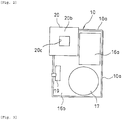
- the lens module 10 is illustrated to disclose an internal circuit board 16b on which a battery 17, a power switch 19, an electronic circuit portion 16a are mounted.
- a front portion of the housing 10a other than a lens housing 20, which is described later, including a barrel 20a (illustrated in Figs. 3 to 5 ) that supports the conversion lens 11 is not illustrated.
- the lens module 10 includes the housing 10a.
- the housing 10a is a planar box-shaped housing other than the lens housing 20, and arranged to place the conversion lens 11 on a lens portion of the camera 2, which is located on the rear surface opposite to the front surface of the smartphone 1 on which a display (not illustrated) is provided.
- the housing 10a is fixed on the smartphone 1 by clipping or banding.
- a clipping member (not illustrated) is provided on the lens module 10 to place the smartphone 1 between the clipping member and the lens module 10. That is, the smartphone 1 is placed between the lens module 10 and the clipping member fixed on the lens module 10 by elastic force.
- the lens module 10 is movable in lateral and longitudinal directions within an allowed range relative to the rear surface of the smartphone 1 to correspond to various types of arrangements of the camera 2 of the smartphone 1.
- an elastic band (not illustrated), such as a rubber band, is installed on the lens module. Similar to a wrist band of a watch, the smartphone 1 is inserted into the internal side of the band to thereby install the lens module 10 on the smartphone 1.
- the conversion lens 11 is also movable in lateral and longitudinal directions relative to the rear surface of the smartphone 1.
- the lens module 10 includes the conversion lens 11 described above, the LEDs 12, 13, an LED driving circuit 14 (illustrated in Fig. 7A ) that drives the LED 12, and an LED driving circuit 15 (illustrated in Fig. 7 ) that drives the LED 13.
- the lens module 10 also includes the lens housing 20 in which the conversion lens 11 is stored, as illustrated in Figs. 4 , 5 .
- the lens housing 20 includes the barrel 20a that supports the conversion lens 11 on the base end side (the side to be mounted on the camera 2), with a tip end surface thereof being formed as an abutting portion 20b that abuts against skin 24 during photographing of the skin 24.
- the abutting portion 20b shields natural light when abutted against the skin 24.
- the abutting portion 20b is provided with a rectangular-shaped (generally square-shaped) opening 20c to allow photographing of a part of the skin 24 facing the opening 20c.
- the barrel 20a is fixed inside the base end portion (the end portion on the side to be mounted on the camera 2) of the lens housing 20, while supporting the conversion lens 11 including the lenses 11a and 11b.
- a second polarizing plate 22 which is described later is also provided.
- an LED substrate 12a illustrated in Figs. 3 to 6 ) including the LEDs 12, 13 to emit illuminating light for photography to the opening 20c of the abutting portion 20b is supported in the lens housing 20.
- the LEDs 12, 13 are provided on the LED substrate 12a. Further, one LED 13 for photographing texture of the skin 24 and two LEDs 12 for photographing blots of the skin 24 are provided, which will be described later.
- the two LEDs 12 on the LED substrate 12a are covered by a first polarizing plate 21 which will be described later.
- the LED driving circuits 14, 15 are also provided on the LED substrate 12a. Alternatively, the LED driving circuits 14, 15 may be provided on the circuit board 16b.
- the LED substrate 12a is arranged in such a manner that the LEDs 12, 13 directly illuminate the skin 24 facing the opening 20c of the lens housing 20.
- the LEDs 12, 13 may irradiate the skin 24 facing the opening 20c by reflecting the light on a half mirror.
- the lens module 10 also includes a power supply circuit 18 (illustrated in Fig. 7A ) and the power switch 19 on the circuit board 16b fixed on the housing 10a, the power supply circuit 18 including a battery 17 that supplies power to the LED driving circuits 14, 15, the CPU 16, and so on.
- a circular-shaped button battery is illustrated as the battery 17, but the battery such as an AAA battery may be used.
- the power switch 19 may be formed using various switches including a slide type switch, a push type switch, etc. It is not limited to place the power switch 19 at the housing portion of a lens 10 for the skin. Alternatively, a push type power switch may be provided at the abutting portion that abuts against the skin.
- the push type power switch may be switched on by bringing the push type power switch to abut against the skin.
- a contact member made of silicone rubber is urged on the outside to project from the abutting portion.
- the power switch is turned on when the contact member abuts against the skin, and the power switch is turned off when the contact member is detached.
- the power switch may be urged by more powerful force to turn on/off by pressing the power switch long by hand. In this case, the power switch is not turned on even when it is abutted against the skin.
- the two LEDs 12, 13 emit slightly different colors of light.
- the LED 12 is used to photograph blots of the skin 24 and emits substantially white light.
- the LED 13 is used to photograph the texture of the skin 24 and emits a near skin color light which includes more yellow component than the light emitting from the LED 12.
- the first polarizing plate 21 is provided on the LED 12 for blot photographing, and the second polarizing plate 22 is provided between the conversion lens 11 and the camera 2. This is to photograph blots located slightly under the surface of the skin 24.
- These polarizing plates 21, 22 facilitate photographing of the blots by largely decreasing the reflection light on the surface of the skin 24, compared to the reflection light inside the skin 24 during photographing of the blots of the skin 24 with the LED 12.
- Polarizing directions of the first polarizing plate 21 and the second polarizing plate 22 are perpendicular to each other. The light of the LED 12 is passed through and polarized by the first polarizing plate 21.
- the polarized light is kept until after the reflection on the skin 24 such that it can hardly be passed through the second polarizing plate 22. Meanwhile, the light reflected inside the skin 24 is not polarized and is able to pass through the second polarizing plate 22.
- the polarizing plates 21, 22 may not be provided.
- the CPU 16 of the electronic circuit portion controls the LED 13 to emit light (turn on) when photographing the texture, while keeping the LED 12 to be turned off, and also controls the LED 12 to emit light when photographing blots, while keeping the LED 13 to be turned off.
- the smartphone 1 has a portable phone function to enable conversation using radio lines.
- the smartphone 1 also includes a display which is not illustrated and can connect to the Internet via radio lines.
- a display which is not illustrated and can connect to the Internet via radio lines.
- APP application
- the smartphone 1 includes control means 3 (illustrated in Fig. 7A ) including a CPU, ROM, RAM, etc., and can execute an APP as a program.
- a flash memory 4 is connected to the control means 3 as a storage apparatus capable of storing APPs (programs), such as downloaded APPs, music files, video files, or picture files.
- the control means 3 can also control the camera 2 to photograph (capture images) and store the captured image data in the flash memory 4. It is also possible to analyze or process image data using an APP for image processing or image analysis.
- the camera 2 includes the image capturing device to enable photographing still images and video images and, for example, photographs an image at a predetermined frame rate of 30 fps.
- control means 3 includes light on/off detection means 3a that detects light on/off of the LEDs 12, 13, photography control means 3b that controls photography by the camera 2 when the light on/off detection means 3a has detected the on/off state of the LEDs 12, 13, and display control means 3c that associates the photographed image taken by the camera 2 according to the control by the photography control means 3b with the LEDs 12, 13 and displays the photographed image on the screen of the portable terminal.
- the lens (lens module) 10 for the skin includes the conversion lens 11 with the LEDs 12, 13, the LED driving circuit 14 that drives the LED 12, and the LED driving circuit 15 that drives the LED 13.
- the lens module 10 also includes the CPU 16 that controls the on/off state of the LEDs 12, 13 as the light source control means via the LED driving circuits 14, 15.
- the CPU 16 is actually not formed by the CPU alone and is formed as an one-chip microcomputer (IC chip) that includes a storage apparatus such as the ROM or the RAM.
- the lens (lens module) 10 for the skin also includes the LED driving circuits 14, 15, the power supply circuit 18 including the battery 17 that supplies power to the LED driving circuits 14, 15, the CPU 16, etc., and the power switch 19.
- the lens (lens module) 10 for the skin includes a lens barrel 20 of the conversion lens 11.
- the lens barrel 20 also functions as a hood, while supporting the conversion lens 11, to shield the natural light with the tip end surface being in contact with the skin.
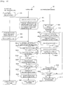
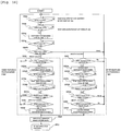
- Example 1 a first example of a method of photographing skin of a face of a person with a portable photography device of a first embodiment will be described by referring to Fig. 8 .
- a user of skin photography device turns on the power supply of the smartphone 1 and selects a "simple diagnosis of skin” application on the screen (step US1).
- photographing processing of the smartphone 1 is started (step SS1).
- a message saying "Turn on the power supply of the skin photography device and set the device on the skin. Touch the shutter button when you are ready.” is displayed (step SS2).
- This message may be a voice message and can be used together with a written message.
- step HS1 when the power switch is turned on (step HS1), the lens 10 is subjected to initialization processing (step HS2) and an LED blinking mode is started. That is, the CPU (light source control means) 16 successively and repeatedly carries out control of the two types of LEDs 12, 13 to turn on/off at predetermined time intervals.
- the LED 13 for texture photographing is turned on for two seconds (step HS3), followed by turning off of the LED 13 for 0.5 second (step HS4).
- the LED 12 for blot photographing is turned on for two seconds (step HS5), and the LED 12 is then turned off for 0.5 second (step HS4).
- steps HS3 to HS5 are repeated successively, and when 30 seconds has passed (step HS6) after the initialization processing (step HS2), the CPU 16 turns off the power supply (step HS7). If 30 seconds has not been passed in step HS6, then steps HS3 to HS5 are successively repeated until 30 seconds has passed (step HS6) and the CPU 16 then turns off the CPU 16 (step HS7).
- the LEDs 13, 12 are successively turned on/off repeatedly at predetermined time intervals (turning on for 2 seconds and turning off for 0.5 second).
- the LEDs 12, 13 is made to blink at predetermined time intervals (e.g., intervals of 0.2 second) for a predetermined time period (e.g., 3 seconds) before 30 seconds has passed in step HS6 and the power supply is turned off in step HS7 to thereby report to the user of the consumption of the battery.
- the above blinking processing should be preset in the LED driving circuits 14, 15 and, when the CPU 16 of the lens 10 for the skin detects the consumption of the battery 17 via the power supply circuit 18, the LED driving circuits 14, 15 are instructed to blink the LEDs 12, 13 as above.
- power supply voltage monitoring means such as a battery voltage drop detecting circuit, is provided in the power supply circuit 18, by including a signal outputting function to output a signal when the voltage of the battery 17 becomes equal to or smaller than a preset reference voltage.
- the LEDs 12, 13 start blinking to cause a rapid voltage drop. Accordingly, the battery voltage drop detecting circuit provided in the power supply circuit 18 is activated before 30 seconds have passed in step HS6 to possibly stop the blinking operation of the LED according to the instruction by the CPU 16. To prevent the blinking of the LED from being ended earlier than a fixed time period (30 seconds) when the battery 17 has been consumed, the following processing will be carried out. Specifically, if the CPU 16 detects a voltage drop of the battery via the battery voltage drop detecting circuit at least once in the 30 seconds in step HS6, such information is recorded as flag information in non-volatile memory, which is not illustrated, provided in the lens 10 for the skin.
- the CPU 16 instructs the LED driving circuits 14, 15 not to turn on the LEDs 12, 13 for photographing the skin next time the power switch 19 is pressed.
- the battery 17 is replaced by new one and the battery voltage of, for example, at least 4.3 V is detected, the flag recorded in the non-volatile memory is cleared (deleted) from the volatile memory.
- Such a user reporting function to report the consumption of the battery 17 and a blinking preventing function to prevent blinking of the LED of less than the fixed time period (30 seconds) while the battery 17 is consumed can be carried out in Examples 2 to 8 which will be described later.
- a user of skin photography device sets the skin photography device connected to the smartphone on the skin (step US2) and touches the shutter button displayed on the screen of the smartphone (step US3).
- a shutter button 1a is displayed on the upper part of the screen by assuming that the shutter button 1a is touched by an index finger while the smartphone 1 is held by hand.
- the shutter button 1a is preferably disposed within 1/5 to 1/3 of the longitudinal size of the screen from the upper end of the screen.
- the shutter button 1b may preferably be disposed in the right half of the above range of the screen and preferably within 1/4 to 1/2 to the left from the right end of the screen, as illustrated in Fig. 7B(b) .
- the shutter button 1b may preferably be disposed at a symmetrical location relative to the position described above. This method is effective when it is assumed that the user operates while seeing the photographing screen using a hand mirror.
- a cancellation button it is also necessary to arrange a cancellation button to cancel photography on the screen, but such a button needs to be disposed at a place where the user most hardly touches erroneously during photographing. It is preferable to dispose such a button at a position in the lower half of the screen or at 1/3 of the longitudinal screen size from the bottom end of the screen, by considering that the user may touch the shutter button by the index finger while holding the smartphone by abutting it against the skin. During cancellation, as the user usually carries out the operation by seeing the screen, it is preferable also visually to arrange the button at 1/5 of the longitudinal screen size from the lower end of the screen.
- step SS3 When the user touches the shutter button, the voice message saying “Photography will be started. Do not move and wait for 5 seconds as it is.” is provided to the user (step SS3).
- a standby state is entered, following step SS3, until the light on/off detection means 3a confirms the off state of the LEDs 12, 13 (step SS4).
- the light on/off detection means 3a detects the on state of the LED 13 for texture photographing by detecting the wavelength of light of the LED 13 (step SS5).
- the photography control means 3b controls photography by the camera 2 at appropriate time during the on state by considering the lighting time (2 seconds) of the LED 13 (step SS6). That is, the shutter sound of the camera 2 is generated to capture a still image. By doing this, a photographed image for the texture can be obtained.
- the standby state is then entered until the light on/off detection means 3a confirms the off state of the LEDs 12, 13 (step SS7).
- the light on/off detection means 3a detects the on state of the LED 12 for blot photographing by detecting the wavelength of light of the LED 12 (step SS8).
- the photography control means 3b controls the photography by the camera 2 at appropriate time during the on state by considering the lighting time (2 seconds) of the LED 12 (step SS9). That is, the shutter sound of the camera 2 is generated to capture a still image. By doing this, a photographed image for the blots can be obtained.
- the display control means 3c associates the two types of photographed images taken by the camera 2 for the texture and the blots with the LEDs 13, 12, respectively, and displays such images on the screen of the smartphone 1 (step SS10). Specifically, the images are displayed by determining whether the photographed image is the image for the texture taken using the LED 13 as the light source, or the image for the blots taken using the LED 12 as the light source.
- the image photographed by the camera 2 in step SS6 is the image for the texture
- the image photographed by the camera 2 in step SS8 is the image for the blots.
- These images photographed by the camera 2 are stored in the memory 4 as the image for the texture and also stored in the memory 4 as the image for the blots. By reading the individual image from the memory 4, it is therefore possible to display the photographed image for the texture and the photographed image for the blots on the screen of the smartphone 1.
- Fig. 8 illustrates the case when the user of skin photography device selects the next application processing (US4) and the process proceeds to the next application processing (step SS11).
- the blots are photographed after photographing the texture, but the photographing order may be reversed.
- the detection of the wavelength of the LED and the time of control processing of the photographing camera would be different depending on the type.
- the lighting time of the LED is set to 2 seconds in this example, but it would substantially be no problem if the time is set to about 1 second.
- the lighting time of the LED has been set to 2 seconds in the present embodiment, but the necessary time for lighting changes depending on the performance of the smartphone 1. If it takes relatively long time for focus adjustment of the camera 2 of the smartphone 1, it is necessary to set long lighting time of the LED. In contrast, however, if the smartphone 1 can quickly carry out the focus adjustment, such long lighting time of the LED may cause a problem of extending the standby time.
- a lighting time changing function to change the lighting time of the LED may be added.
- several lighting time periods e.g., 1.5 seconds, 2.0 seconds, 2.5 seconds, and 3.0 seconds, etc.
- the CPU 16 should detect the long pressing and instruct the LED driving circuits 14, 15 to successively change (switch) the lighting time of the LED (e.g., in order of 1.5 seconds, 2.0 seconds, 2.5 seconds, and 3.0 seconds).
- Such an LED lighting time changing function may be added similarly to Examples 2 to 8 which will be described later.
- the reporting may be carried out by providing an LED capable of emitting multiple types of light in the power switch 19 and associating the multiple colors of illumination of the LED with multiple lighting time periods. The color of the illumination of the LED is changed each time the power switch 19 is pressed long.
- LEDs may be provided at appropriate portions of the lens module 10 according to the lighting time period of the LED to turn on the LED that corresponds to the lighting time of the LED each time the power switch 19 is pressed long.
- the processing needs to be redone.
- the light source control means (CPU) 16 controls the light sources of LEDs 13, 12 to successively repeat turning on and turning off the LEDs 13, 12 at predetermined time intervals
- the photography control means 3b lets the camera 2 to carry out photography.
- the light on/off detection means 3a holds the photography by the camera to standby until the light on/off detection means detects the wavelength of the LED 12 or the LED 13.
- the photographed image taken by the camera 2 is associated with the LED 12 or the LED 13 and displayed on the screen of the smartphone 1 by the display control means 3c, such that the user can easily confirm the type of the photographed image displayed on the screen. That is, the user can easily confirm whether the image is the photographed image for the texture or the photographed image for the blots.
- Example 1 the texture is photographed first by the camera 2 by detecting the wavelength of the LED 13 for texture photographing and, after the off state of the LEDs 13, 12 is confirmed, the wavelength of the LED 12 for blot photographing is detected.
- An advantage of this system is an ability to use either type of lens for the skin without changing the software on the smartphone 1 side, even when the time to detect the LED wavelength and the photography control time of the camera become shorter as a result of improved performance or the like of the smartphone 1, and a new type of the lens for the skin having a shorter lighting time of the LED 12 for blot photographing and the LED 13 for texture photographing than 2 seconds on the lens 10 side is introduced. Meanwhile, if the lighting time of 2 seconds of the LED 12 for blot photographing and the LED 13 for texture photographing is not going to be changed in the future, turning off the LEDs 12, 13 for 0.5 second after the on state of the LED 13 may be omitted on the condition that the lighting time of 2 seconds of the LED 13 for texture photographing is not changed.
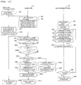
- a control sequence of this case will be described below. That is, in Example 2, a second example of the method of photographing skin of a face of a person with a portable photography device of the first embodiment will be described by referring to Fig. 9 .
- steps US1 to US4 and steps SS1 to SS3 are similar to those in Example 1 and the description thereof will not be repeated.
- the CPU (light source control means) 16 repeatedly controls, after the initialization processing, the two types of LEDs 13, 12 to turn on the LEDs 13, 12 successively for a predetermined time period (2 seconds), and after having turned on the LEDs 13, 12, turn off the LEDs 13, 12 for a predetermined time period (0.5 second).
- the CPU 16 first turns on the LED 13 for texture photographing for 2 seconds (step HS13), and then turns on the LED 12 for blot photographing for 2 seconds while turning off the LED 13 (step HS14). As the LED 12 is turned on simultaneously with turning off of the LED 13, both LEDs 13, 12 are not turned off simultaneously while the LEDs 13, 12 are turned on/off. After that, the LEDs 13, 12 are turned off for 0.5 second (step HS15).
- Steps HS13 to HS15 are carried out successively and repeatedly and, when 30 seconds has passed (step HS16) after the initialization processing (step HS2), the CPU 16 turns off the power supply (step HS17). If 30 seconds has not been passed in step HS16, then steps HS13 to HS15 are carried out successively and repeatedly until 30 seconds has passed (step HS16), and then the CPU 16 turns off the power supply (step HS17).
- the control is carried out repeatedly to turn on the LEDs 13, 12 successively for the predetermined time period (2 seconds) and, after having turned on the LEDs 13, 12, turn off the LEDs 13, 12 for the predetermined time period (0.5 second).
- the light on/off detection means 3a enters the standby state after step SS3 until the off state of the LEDs 12, 13 is confirmed (step SS14). Upon confirmation of the off state of the LEDs 12, 13 in step SS14, the light on/off detection means 3a detects the on state of the LED 13 for texture photographing by detecting the wavelength of light of the LED 13 (step SS15).
- a timer is started (step SS16).
- the timer is installed in the smartphone 1 as a clock function to allow the control means 3 to carry out ON/OFF control of the timer and detect elapsed time in the timer.
- the photography control means 3b controls photography by the camera 2 (step SS17). That is, the shutter sound of the camera 2 is generated to capture a still image. Since the on state of the LED 13 for texture photographing has been confirmed in step SS15, it is possible to obtain a photographed image for the texture.
- the LED 13 for texture photographing is lighted for 2 seconds and, when the control means 3 detects that 2 seconds has passed with the timer (step SS18), the photography control means 3b carries out the photography control of the camera 2 (step SS19). That is, the shutter sound of the camera 2 is generated to capture a still image. Since the on state of the LED 13 for texture photographing is confirmed in step SS15 and 2 seconds has passed after turning on, the LED 12 for blot photographing is being turned on in step SS19. As a result, the photographed image for the blots can be obtained.
- the photography control means 3b thus carries out photography control of the camera at predetermined time intervals (2 seconds) in synchronization with turning on of the LEDs 13, 12, the photographed images for the texture and the blots can be obtained.
- the display control means 3c associates the two types of photographed images for the texture and the blots, which have been photographed by the camera 2, with the LEDs 13, 12 and displays the images on the screen of the smartphone 1 (step SS20). Specifically, the images are displayed by determining whether the photographed image is the image for the texture taken using the LED 13 as the light source, or the image for the blots taken using the LED 12 as the light source. Since the image photographed by the camera 2 in step SS17 is the image for the texture and the image photographed by the camera 2 in step SS19 is the image for the blots, the individual images photographed by the camera 2 are stored in the memory 4 as the image for the texture and also stored in the memory 4 as the image for the blots. By reading the individual image from the memory 4, it is therefore possible to display the photographed image for the texture and the photographed image for the blots on the screen of the smartphone 1.
- the user selects ending the photography processing of the smartphone 1, restarting the photography, or selecting the next application processing by the user of skin photography device.
- the user of skin photography device selects the next application processing (US4) and the process moves to the next application (step SS11).
- the blots are photographed after photographing the texture, but the photographing order may be reversed.
- the CPU (light source control means) 16 repeatedly controls the two types of LEDs 13, 12 to successively turn on the LEDs 13, 12 for the predetermined time period and, after having turned on the LEDs 13, 12, turn off the LEDs 13, 12 for the predetermined time period (0.5 second).
- the photography control means 3b controls photography by the camera 2.
- the photography control means 3b then controls the photography by the camera 2 at the predetermined time intervals (2 seconds) by the timer in synchronization with turning on of the LED 12. It is possible, therefore, to reliably carry out photography by the camera 2 of the smartphone 1 by using the two types of LEDs 13, 12.
- there is an advantage that the photography using the two types of LEDs 13, 12 can be carried out only by detecting the off state of the LEDs 13, 12 and, after the off state, detecting the first lighting of the LED 13 by the light on/off detection means 3a.
- the user can easily confirm the type of the photographed image displayed on the screen of the smartphone 1, as in Example 1, as the photographed image taken by the camera 2 is associated with the LED 13 or the LED 12 and displayed on the screen of the smartphone 1 by the display control means 3c. That is, the user can easily confirm whether the image is the photographed image for the texture or the photographed image for the blots.
- the photography by the camera is started after having waited for the detection of the wavelength of the LED 13 for texture photographing.
- the photography by the camera is started next time the LED 13 for texture photographing is turned on after the LED 13 for texture photographing is turned off and the LED 12 for blot photographing is turned on and off.
- the lighting time is set to 2.2 seconds. The control sequence of this case will be described by referring to Fig. 10 .
- steps US1 to US4, steps SS1 to SS3, and steps HS1 to HS7 are similar to those in Example 1 and the description thereof will not be repeated.
- This example differs from Example 1 in that the lighting time of the LED 13 for texture photographing is set to 2.2 seconds in step HS3, and the lighting time of the LED 12 for blot photographing is set to 2.2 seconds in step HS5.
- the control is carried out repeatedly to turn on the LEDs 13, 12 successively for the predetermined time period (2.2 seconds) and, after the LED 13, 12 is turned off, turn off the LEDs 13, 12 for the predetermined time period (0.5 second). Since which LED (LED 12 or 13) is turned on after the LEDs 12, 13 are turned off is not known, the smartphone 1 identifies the wavelength of the LED to determine which LED (LED 13 or LED 12) has been turned on (steps SS26 and SS31). In Fig.
- step HS3(5) a step of "photographing the texture or blots and turning on the LED for 2.2 seconds" is indicated by step HS3(5), while a step of “photographing the blots or texture and turning on the LED for 2.2 seconds" is indicated by step HS5(3).
- the light on/off detection means 3a enters the standby state after step SS3 until the off state of the LEDs 12, 13 is confirmed (step SS24). After the confirmation of the off state of the LEDs 12, 13 in step SS24, the light on/off detection means 3a detects the lighting of the LED 12 or LED 13 (step SS25) and identifies the wavelength of the LED 12 or LED 13 (step SS26), in order to determine whether the LED which is being turned on is the LED 12 for blot photographing or the LED 13 for texture photographing.
- the photography control means 3b controls the photography by the camera 2 (step SS27). That is, the shutter sound of the camera 2 is generated to capture a still image. By doing this, the photographed image for the texture can be obtained.
- the photography control means 3b controls the photography by the camera 2 (step SS28). That is, the shutter sound of the camera 2 is generated to capture a still image. By doing this, the photographed image for the blots can be obtained.
- the standby state is entered until the light on/off detection means 3a confirms the off state of the LEDs 12, 13 (step SS29).
- the light on/off detection means 3a detects the on state of the LEDs 12, 13 (step SS30) as in step SS25, and identifies the wavelength of the LEDs 12, 13 (step SS31) as in step SS26, to determine whether the LED being turned on is the LED 12 for blot photographing or the LED 13 for texture photographing.
- the photography control means 3b controls the photography by the camera 2 (step SS32). That is, the shutter sound of the camera 2 is generated to capture a still image. By doing this, the photographed image for the texture can be obtained.
- the photography control means 3b controls the photography by the camera 2 (step SS33). That is, the shutter sound of the camera 2 is generated to capture a still image. By doing this, the photographed image for the blots can be obtained.
- the photography is carried out two times each for the texture photographing and the blot photographing.
- the display control means 3c associates the two types of photographed images for the texture and the blots, which have been photographed by the camera 2, with the LEDs 13, 12 and displays the images on the screen of the smartphone 1 (step SS34). Specifically, the images are displayed by determining whether the photographed image is the image for the texture taken using the LED 13 as the light source, or the image for the blots taken using the LED 12 as the light source.
- Fig. 10 illustrates the case where the user of skin photography device selects the next application processing (US4) and the process proceeds to the next application processing (step SS11).
- Example 2 a similar effect as in Example 1 can be obtained, and an advantage of preventing variation of time before the start of photography due to different timing of touching the shutter button can also be obtained.
- the LEDs having small deviation from the prescribed values should be installed on the lens 10 for the skin as the LEDs 13, 12 for texture photographing and blot photographing, in order to prevent erroneous identification of the wavelength of the LED 12 for blot photographing or the wavelength of the LED 13 for texture photographing on the side of the smartphone 1.
- actual wavelengths of the LEDs fluctuate, and the LEDs having wavelengths closer to the prescribed values are selected and used. This causes a cost increase of the LEDs.
- Example 4 below it is described that the allowable deviation value from the prescribed value is increased in order to decrease the cost of the LEDs.
- both LEDs 13, 12 should be compared relatively with each other, instead of identifying the wavelength components of the LEDs based on absolute values, to thereby identify the LED having a wavelength component closer to red as the LED 13 for texture photographing and the LED having a wavelength component closer to blue as the LED 12 for blot photographing.
- the control sequence of this case will be described by referring to Fig. 11 .
- steps US1 to US4, steps SS1 to SS3, and steps HS1 to HS7 are similar to those in Example 3 and the description therefor will not be repeated.
- a standby state is entered, following step SS3, until the light on/off detection means 3a confirms the off state of the LEDs 12, 13 (step SS4).
- the light on/off detection means 3a detects the lighting of either the LED 12 or LED 13 (step SS40).
- the light on/off detection means 3a only detects the lighting of the LEDs and does not identify whether the LED is the LED 13 for texture photographing or the LED 12 for blot photographing.
- the photography control means 3b controls the photography by the camera 2 (SS41). That is, the shutter sound of the camera 2 is generated to capture a still image. By doing this, a photographed image for the texture or for the blots can be obtained.
- the standby state is entered until the light on/off detection means 3a confirms the off state of the LEDs 12, 13 (step SS42).
- the light on/off detection means 3a detects the lighting of the LED 12 or the LED 13 (step SS43).
- the light on/off detection means 3a only detects the lighting of the LEDs and does not identify the LED as the LED 13 for texture photographing or the LED 12 for blot photographing. In step SS43, however, if the LED 13 for texture photographing is on in step 40, the LED 12 for blot photographing comes to be turned on in step SS43. In contrast, if the LED 12 for blot photographing is lighting in step 40, the LED 13 for texture photographing comes to be turned on.
- the photography control means 3b Upon detecting the lighting of the LED, the photography control means 3b carries out the photography control of the camera 2 (step SS44). That is, the shutter sound of the camera 2 is generated to capture a still image. By doing this, a photographed image for the texture or for the blots can be obtained.
- step SS44 the photographed image for the blots can be obtained, if the photographed image for the texture has been obtained in step SS41.
- the photographed image for the texture can be obtained, if the photographed image for the blots has been obtained in step SS41.
- the display control means 3c compares the wavelength components of the photographed images obtained in step SS41 and step SS44, and stores images having relatively more red components in a flash memory 4 as the image for the texture (step SS45), and images having relatively more blue components are stored in the flash memory (4) (step SS46).
- the order of executing step SS45 and step SS46 may be reversed.
- the display control means 3c associates the two types of photographed images for the texture and the blots, which have been photographed by the camera 2, with the LEDs 13, 12 and displays the images on the screen of the smartphone 1 (step SS47). Specifically, the images are displayed by determining whether the photographed image is the image for the texture taken using the LED 13 as the light source, or the image for the blots taken using the LED 12 as the light source.
- Fig. 11 illustrates the case where the user of skin photography device selects the next application processing (US4) and the process proceeds to the next application processing (step SS11).
- Example 4 a similar effect as in Example 4 can be obtained.
- there is an advantage that an allowed deviation from a prescribed value of the LED can be increased to suppress the cost of the LED.
- the off state of the LED 13 for texture photographing and the LED 12 for blot photographing is confirmed, followed by the detection of the wavelength of the LEDs and the confirmation of the lighting of the LED 13 for texture photographing, in order to control the photography by the camera 2.
- the off state of the LED 13 for texture photographing and the LED 12 for blot photographing is confirmed, followed by the confirmation of the lighting of the LED 12 for blot photographing, in order to control the photography by the camera 2.
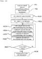
- Example 5 only the first confirmation of the off state of the LEDs 12, 13 is carried out to increase the processing speed. The control sequence of this case will be described by referring to Fig. 12 .
- steps US1 to US4, steps SS1 to SS3, and steps HS1 to HS7 are similar to those in Example 1 and the description thereof will not be repeated.
- a standby state is entered, following step SS3, until the light on/off detection means 3a confirms the off state of the LEDs 12, 13 (step SS4).
- the timer is installed in the smartphone 1 as a clock function to allow the control means 3 to carry out ON/OFF control of the timer and detect elapsed time in the timer.
- step SS50a the timer is started (step SS50a), and when 1 second has passed, the light-off detection means 3a detects the on state of the LEDs 12, 13 and identifies the wavelengths of the LEDs 12, 13 (step SS51).
- the photography control means 3b controls the photography by the camera 2 (step SS53). That is, the shutter of the camera 2 is released. By doing this, the photographed image for the texture can be obtained.
- the LED 13 is turned on for 2 seconds after the LEDs 12, 13 are turned off, the LED 12 is turned on for 2 seconds, and the LEDs 12, 13 are turned off for 0.5 second.
- the shutter of the camera 2 is released 0.5 to 1.0 second after the start of lighting of the LED 13, that is, almost in the middle (center point of time) of the time interval while the LED 13 is in the on state.
- the photography control means 3b carries out the photography control of the camera 2 (step SS55). That is, the shutter of the camera 2 is released. By doing this, the photographed image for the blots can be obtained. Since the LED 12 is turned on for 2 seconds after the LEDs 12, 13 are turned off, the LED 13 is turned on for 2 seconds, and the LEDs 12, 13 and turned off for 0.5 second. Thus, the shutter of the camera 2 is going to be released almost in the middle (center point of time) of the time interval while the LED 12 is in the on state.
- the display control means 3c associates the two types of photographed images taken by the camera 2 for the texture and the blots, respectively, with the LEDs 13, 12 and displays the images on the screen of the smartphone 1 (step SS10). Specifically, the images are displayed by determining whether the photographed image is the image for the texture taken using the LED 13 as the light source, or the image for the blots taken using the LED 12 as the light source.
- Fig. 12 illustrates the case where the user of skin photography device selects the next application processing (US4) and the process proceeds to the next application processing (step SS11).
- Example 2 a similar effect as in Example 1 can be obtained.
- the first confirmation of the off state of the LEDs 12, 13 is carried out to increase processing speed.
- the photographing by the camera 2 is carried out almost in the middle (center point of time) of the time interval while the LEDs 12, 13 are in the on state, it is possible to reliably carry out photography.
- Example 2 turning off the LEDs 12, 13 for 0.5 second has been omitted.
- Example 6 the identification of the wavelengths of the LEDs is also omitted. The control sequence of this case will be described by referring to Fig. 13 .
- steps US1 to US4, steps SS1 to SS3, and steps HS1 to HS7 are similar to those in Example 2 and the description thereof will not be repeated.
- the control on the side of the lens 10 for the skin is different from that of Example 2 in that, subsequent to the initialization processing, the CPU (light source control means) 16 repeatedly controls the LEDs 13, 12 to turn off first for a predetermined time period (0.5 second) (step SS15), followed by turning on of the two types of LEDs 13, 12 successively for a predetermined time period (2 seconds). After the turning on of the LEDs 13, 12, the LEDs 12, 13 are turned off for the predetermined time period (0.5 second).
- the photography control means 3b controls the photography by the camera 2 (step SS63). That is, the shutter of the camera 2 is released.
- the photographed image for the texture can be obtained.
- the photographed image for the texture can be obtained by releasing the shutter of the camera 2, as the LED 13 for texture photographing is first turned on after the LEDs 12, 13 are turned off. Since the LED 13 is turned on for 2 seconds after the LEDs 12, 13 are turned off, the shutter of the camera 2 is released almost in the middle (center point of time) (0.5 to 1.0 second after the start of lighting) of the 2 seconds while the LED 13 is in the on state.
- the photography control means 3b controls the photography by the camera 2 (step SS64). That is, the shutter of the camera 2 is released. By doing this, the photographed image for the blots can be obtained. Since the LED 12 is turned on for 2 seconds after the LEDs 12, 13 are turned off and the LED 13 is turned on for 2 seconds, the shutter of the camera 2 is released almost in the middle (center point of time) (0.5 to 1.0 second after the start of lighting) of the time interval while the LED 12 is in the on state.
- the display control means 3c associates the two types of photographed images taken by the camera 2 for the texture and the blots, respectively, with the LEDs 13, 12 and displays the images on the screen of the smartphone 1 (step SS10). Specifically, the images are displayed by determining whether the photographed image is the image for the texture taken using the LED 13 as the light source, or the image for the blots taken using the LED 12 as the light source.
- Fig. 13 illustrates the case where the user of skin photography device selects the next application processing (US4) and the process proceeds to the next application processing (step SS11).
- Example 2 a similar effect as in Example 2 can be obtained, and an advantage of reliably carrying out photography, because the photography by the camera 2 is carried out in the middle (center point of time) of the time interval while the LEDs 12, 13 are in the on state, can also be obtained.
- the photography by the camera is controlled 0.5 second after the start of lighting of the LED at the earliest.
- the photography by the camera may be started when the lighting of the LED is started, because the photography cannot be started 0.0 second after the start of controlling the photography by the camera.
- the LEDs 12, 13 upon turning on of the power supply of the lens 10 for the skin, the LEDs 12, 13 are configured to be turned on alternately and then turned off after the predetermined time period has passed. It is possible to prevent consumption of the battery by the following procedures.
- the lens 10 for the skin may be provided with an illumination detection apparatus or a dual-tone multi-frequency (DTMF) detection apparatus to recognize touching of the shutter button, and the flash light may be emitted or the sound of a predetermined musical scale (a musical scale that is hardly confused with environmental noise and easily detected by the detection apparatus) may be generated.
- the LED 13 for texture photographing is then turned on for 2 seconds and the LED 13 for blot photographing is turned on for 2 seconds.
- the shutter is released at the center point of time of the 2 seconds for each LED to prevent consumption of the battery.
- the LED of the lens for the skin is automatically turned off 30 seconds after turning on of the power switch to suppress the power consumption caused by forgetting turning off of the light.
- the time may be freely set by operating the application by the user.
- the lens 10 for the skin is provided with the switching means that is manually turned on/off, such that the user may turn on the switch by hand before photography to start the light on/off control of the LEDs 12, 13. Further, it may also possible to turn on a second switch automatically (without intentionally operating the switch to turn on by the user) to start the light on/off control of the LEDs 12, 13 by bringing the camera for the skin to the skin by the user. As a result, the power consumption is suppressed and the operability by the user is improved, such that the influence of the natural light can be reduced as follows.
- the main switch may be eliminated and replaced by the second switch means.
- the second automatic switch means may include the following:
- the CPU 16 detects switching of the inside state of the lens barrel from the bright state to the dark state according to a signal from the photo sensor, and the CPU 16 turns on the switch (power switch 19). In contrast, when the CPU 16 detects the switching of the inside state of the lens barrel from the dark state to the bright state, the CPU 16 turns off the switch (power switch 19).
- the on/off state of the LEDs 12, 13 is identified depending on whether an image received by the camera is bright or dark. However, it is necessary to be careful for the case where the bright state is caused by the entering of the natural light other than the lighting of the LEDs 12, 13.
- Bright case modes and dark case modes are listed in Table 1 below. [Table 1] State No. State matrix Image received by camera Closeness of lens to skin On/off state of LED Natural light incident on lens 1 Yes On No Bright 2 Yes Off No Dark 3 No On Yes Bright 4 No On No Dark 5 No Off Yes Bright 6 No Off No Dark
- State Nos. 1 and 2 are normal photography states, but when the lens is not in close contact with the skin as in state Nos. 3 to 6, the brightness of the image received by the camera depends on the presence or absence of the natural light incident on the lens.
- a switch may be provided at a portion of the lens which is in close contact with the skin to turn on the power switch of the skin photographing apparatus and start blinking processing of the LED by bringing the lens to be in close contact with the skin.
- a photographing processing of this case proceeds as illustrated in Table 2. [Table 2] No.
- the processing can be carried out by assuming that the lens is in close contact with the skin and no incident natural light is present. If a system in which the power switch of the lens 10 for the skin is turned on while the lens 10 for the skin is in close contact with the skin is not adopted, it may happen that 30 seconds have already passed and the LED is no longer lighted when the lens for the skin is abutted against the skin after turning on of the power switch. Such a problem does not occur when this system is adopted.
- the identification of the LED 13 for the texture and the LED 12 for the blots is carried out according to the wavelengths of the LEDs 12, 13.
- the identification of the LED may be carried out according to the timing of turning on/off the LEDs 12, 13.
- Figs. 14 and 15 illustrate the processing sequence of Example 7.
- the LEDs 12, 13 are identified by the length of the off state time.
- Fig. 14 illustrates the processing sequence on the side of the skin measuring apparatus (the lens 10 for the skin).
- Fig. 15 illustrates the processing sequence on the side of the smartphone 1.
- steps US1 to US4 and steps SS1 to SS3 are similar to those in Example 5 and the description thereof will not be repeated.
- the power switch is automatically turned on (without intentionally operated to turn on the switch by the user) (HS1), and the initialization processing is carried out (HS2).
- the timer is set to 30 seconds (step HS21).
- step HS23 After the LED 13 for texture photographing is turned on for 2 seconds (step HS23), the LED 13 is turned off for 0.5 second (step HS24). After the LED 12 for blot photographing is turned on for 2 seconds (step HS25), the LED 12 is turned off for 1 second (step HS26).
- steps HS23 to HS26 are carried out successively and repeatedly and, when 30 seconds has passed (step HS27) after the timer is set (step HS21), the CPU 16 turns off the power supply (step HS28). If 30 seconds has not been passed in step HS27, steps HS23 to HS26 are carried out successively and repeatedly and, when 30 seconds has passed (step HS27), the CPU 16 turns off the power supply (HS28).
- the LED 13 for the texture is turned on for 2 seconds and then turned off for 0.5 second
- the LED 12 for the blots is turned on for 2 seconds and then turned off for 1 second. It is possible, therefore, to identify which LED is in the on state according to the length of the off state time.
- the smartphone 1 enters the standby state, after step SS3, until the light on/off detection means 3a detects the on state of either the LED 12 or 13 (step SS4a). After the on state of the LED is detected, the standby state is entered until the off state of the LED having been turned on is detected (step SS4b).
- the timer is installed in the smartphone 1 as a clock function to allow the control means 3 to carry out on/off control of the timer and detect the elapsed time in the timer.
- the timer measures time between the turning off of the LED in step SS4b and the turning on of the LED in step SS51a to obtain a timer value (off state time) (step SS50b).
- step SS50b If the timer value obtained in step SS50b is about 0.5 second, this indicates that the LED 13 for the texture is in the off state. Subsequently, the LED 12 for the blots is going to be turned on.
- the photography control means 3b controls the photography by the camera 2 at appropriate time during the on state by considering the lighting time (2 seconds) of the LED 12 (step SS52a). That is, the shutter of the camera 2 is released. By doing this, the photographed image for the blots can be obtained.
- step SS50b If the timer value obtained in step SS50b is about 1.0 second, the process proceeds to processing described later (step SS54a). If the timer value is other than about 0.5 second or about 1.0 second, the process returns to step SS4a.
- the timer measures time between the turning off of the LED 12 in step SS52b and the turning on of the LED 13 to obtain a timer value (off state time) (step SS52e).
- step SS52e If the timer value obtained in step SS52e is about 1.0 second, this indicates that the LED 12 for the blots is in the off state. Subsequently, the LED 13 for the texture is going to be turned on.
- the photography control means 3b controls the photography by the camera 2 at appropriate time during the on state by considering the lighting time (2 seconds) of the LED 13 (step SS52f). That is, the shutter of the camera 2 is released. By doing this, the photographed image for the texture can be obtained.
- step SS52e If the timer value obtained in step SS52e is other than about 1.0 second, the process returns to step SS4a.
- step SS50b If the timer value obtained in step SS50b is about 1.0 second, this indicates that the LED 12 for the blots is in the off state. Subsequently, the LED 13 for the texture is going to be turned on.
- the photography control means 3b controls the photography by the camera 2 at appropriate time during the on state by considering the lighting time (2 seconds) of the LED 13 (step SS54a). That is, the shutter of the camera 2 is released. By doing this, the photographed image for the texture can be obtained.
- step SS54d When the on state of the LED 13 is detected (step SS54d), the timer measures time between the turning off of the LED 13 in step SS54b and the turning on of the LED 12 to obtain a timer value (off state time) (step SS54e).
- step SS54e If the timer value obtained in step SS54e is about 0.5 second, this indicates that the LED 13 for the texture is in the off state. Subsequently, the LED 12 for the blots is going to be turned on.
- the photography control means 3b controls the photography by the camera 2 at appropriate time during the on state by considering the lighting time (2 seconds) of the LED 12 (step SS54f). That is, the shutter of the camera 2 is released. By doing this, the photographed image for the blots can be obtained.
- step SS54e If the timer value obtained in step SS54e is other than about 0.5 second, the process returns to step SS4a.
- the display control means 3c associates the two types of photographed images taken by the camera 2 for the texture and the blots, respectively, with the LEDs 13, 12 and displays the images on the screen of the smartphone 1 (step SS10). Specifically, the images are displayed by determining whether the photographed image is the image for the texture taken using the LED 13 as the light source, or the image for the blots taken using the LED 12 as the light source.
- Fig. 15 illustrates the case where the user of skin photography device selects the next application processing (US4) and the process proceeds to the next application processing (step SS11).
- the identification of the LED is carried out according to the timing of turning on/off the LEDs 12, 13 to increase the processing speed.
- the off state time is different for the LEDs 12, 13, it may also be possible to provide an identical off state time for the LEDs 12, 13, while providing different lighting time for the LED 13 for the texture and the LED 12 for the blots of, e.g., 1.5 seconds and 2.0 seconds, respectively.
- By measuring the lighting time of the LED that is turned on after the first off state it is determined which of the LED 13 for the texture and the LED 12 for the blots has been turned on to start photography next time the LED is turned on.
- This example is made from Example 7 combined with identification according to the wavelengths of the LEDs. It is possible to eliminate erroneous photography when the wavelength of the natural light is incidentally identical to the wavelengths of the LED for the texture and the LED for the blots, or when the brightening/darkening timing of the natural light is incidentally identical to the turning on/off timing of the LEDs.
- the processing sequence on the side of the lens 10 for the skin is the same as that of Example 7 illustrated in Fig. 14 , and the description thereof will not be repeated.
- step SS4a proceeds from step SS4b to steps SS4b, SS50a, SS51a, and SS50b, in the smartphone 1, as in Example 7 illustrated in Fig. 15 .
- the light on/off detection means 3a detects the on state of the LED 12 by detecting the wavelength of light of the LED 12 for blot photographing (step SS52).
- the photography control means 3b controls the photography by the camera 2 at appropriate time while the LED 12 is in the on state (step SS52a). That is, the shutter sound of the camera 2 is generated to capture a still image. By doing this, the photographed image for the blots can be obtained.
- the timer measures time between the turning off of the LED 12 in step SS52b and the turning on of the LED 13 to obtain a timer value (off state time) (step SS52e).
- step SS52e If the timer value obtained in step SS52e is about 1.0 second, this indicates that the LED 12 for the blots is in the off state. Subsequently, the LED 13 for the texture is going to be turned on.
- the light on/off detection means 3a detects the on state of the LED 13 by detecting the wavelength of light of the LED 13 for texture photographing (step SS53).
- the photography control means 3b controls the photography by the camera 2 at appropriate time while the LED 13 is in the on state (step SS52f). That is, the shutter sound of the camera 2 is generated to capture a still image. By doing this, the photographed image for the texture can be obtained.
- the light on/off detection means 3a detects the on state of the LED 13 for texture photographing by detecting the wavelength of light of the LED 13 (step SS53).
- the photography control means 3b controls the photography by the camera 2 at appropriate time while the LED 13 is in the on state (step SS54a). That is, the shutter sound of the camera 2 is generated to capture a still image. By doing this, the photographed image for the texture can be obtained.
- step SS54d When the on state of the LED 13 is detected (step SS54d), the timer measures time between the turning off of the LED 13 in step SS54b and the turning on of the LED 12 to obtain a timer value (off state time) (step SS54e).
- step SS54e If the timer value obtained in step SS54e is about 0.5 second, this indicates that the LED 13 for the texture is in the off state. Subsequently, the LED 12 for the blots is going to be turned on.
- the light on/off detection means 3a detects the on state of the LED 12 for blot photographing by detecting the wavelength of light of the LED 12 (step SS52).
- the photography control means 3b controls the photography by the camera 2 at appropriate time while the LED 12 is in the on state (step SS54f). That is, the shutter sound of the camera 2 is generated to capture a still image. By doing this, the photographed image for the blots can be obtained.
- the display control means 3c associates the two types of photographed images taken by the camera 2 for the texture and the blots, respectively, with the LEDs 13, 12 and displays the images on the screen of the smartphone 1 (step SS10). Specifically, the images are displayed by determining whether the photographed image is the image for the texture taken using the LED 13 as the light source, or the image for the blots taken using the LED 12 as the light source.
- Fig. 16 illustrates the case where the user of skin photography device selects the next application processing (US4) and the process proceeds to the next application processing (step SS11).
- the on state of the LEDs 12, 13 is detected by detecting the wavelengths of light of the LEDs 12, 13 by the light on/off detection means 3a.
- the types of the LEDs may be identified by measuring the lighting time of the LED.
- Example 8 In the description of Example 8 or the like, such phrases as detection of the wavelengths, detection of the LED for the blots, etc. have been used, but it would be preferable in the actual processing to use colors that change according to the wavelength, instead of measuring the wavelengths themselves.
- Fig. 17 is a block diagram illustrating a portable photography device according to a second embodiment of the present invention.
- the portable photography device according to the present embodiment differs from the portable photography device according to the first embodiment in that transmission/reception means is provided in the smartphone 1 and the lens 10 for the skin (lens module) to allow transmission/reception of data and signals to and from these constituent components. This point, therefore, will be described in detail below.
- the same reference signs are given to the constituent components similar to those in the first embodiment and the description thereof will not be repeated or otherwise provided in a simplified manner.
- the lens 10 for the skin includes transmission/reception means 25 that receives a light-source turn-on instruction signal and a light-source turn-off instruction signal from the smartphone 1, while transmitting a light-source turn-on reporting signal and a light-source turn-off reporting signal to the smartphone 1.
- the transmission/reception means 25 is formed, for example, by a Bluetooth module 25 which is controlled by the CPU 16.
- the light-source turn-on instruction signal is a signal to turn on the LEDs 12, 13, while the light-source turn-off instruction signal is a signal to turn off the LEDs 12, 13.
- the light-source turn-on reporting signal is a signal to report that the LEDs 12, 13 have been turned on, while the light-source turn-off reporting signal is a signal to report that the LEDs 12, 13 have been turned off.
- the CPU (light source control means) 16 is configured to turn on the LEDs 12, 13 and cause the transmission/reception means 25 to transmit the light-source turn-on reporting signal to the smartphone 1 when the light-source turn-on instruction signal is received from the smartphone 1 via the transmission/reception means 25.
- the CPU 16 turns off the LEDs 12, 13 and cause the transmission/reception means to transmit the light-source turn-off reporting signal to the smartphone 1.
- the smartphone 1 includes transmission/reception means 26 of the smartphone (transmission/reception means on the terminal side) that receives the light-source turn-on reporting signal and the light-source turn-off reporting signal from the transmission/reception means 25 of the lens (lens module) 10 for the skin, and transmits the light-source turn-on instruction signal and the light-source turn-off instruction signal to the lens (lens module) 10 for the skin (hereinafter the transmission/reception means 26 of the smartphone will be referred to as the transmission/reception means 26).
- the transmission/reception means 26 includes, for example, a Bluetooth module 26 which is controlled by the control means 3.
- the control means 3 is configured to cause the camera 2 to carry out photography when the light-source turn-on reporting signal is received from the lens (lens module) 10 for the skin via the transmission/reception means 25, 26.
- the light-source turn-off instruction signal is transmitted to the lens (lens module) 10 for the skin via the transmission/reception means 25, 26.
- the light-source turn-off reporting signal is received from the lens (lens module) 10 for the skin via the transmission/reception means 26, 25, the light-source turn-on instruction signal is transmitted to the lens (lens module) 10 for the skin via the transmission/reception means 25, 26.
- the display control means 3c is also configured to associate the photographed image taken by the photography control means 3b with the LEDs 12, 13 and displays the image on the screen of the smartphone 1.
- a user of skin photography device turns on the power supply of the smartphone 1 and selects a "simple diagnosis of skin” application on the screen (step US1).
- photographing processing of the smartphone 1 is started (step SS1).
- a message saying "Turn on the power supply of the skin photography device and set the device on the skin. Touch the shutter button when you are ready” is displayed (step SS2).
- a user of skin photography device sets the skin photography device connected to the smartphone on the skin (step US2) and touches the shutter button displayed on the screen of the smartphone (step US3).
- step HS1 when the power switch is turned on (step HS1), the lens 10 for the skin is subjected to initialization processing (step HS2), and the transmission/reception means 25 formed by the Bluetooth module enters a reception standby state (step HS70).
- the control means 3 of the smartphone 1 When the user of skin photography device (user) touches the shutter button on the screen of the smartphone 1, the control means 3 of the smartphone 1 generates a turn-on command (light-source turn-on instruction signal) to turn on the LED 13 for texture photographing (step SS70).
- the turn-on command is transmitted as a signal from the transmission/reception means 26, and this signal is received by the transmission/reception means 25 of the lens 10 for the skin.
- the LED 13 for texture photographing is turned on (step HS71).
- an LED turn-on reporting signal (light-source turn-on reporting signal) is transmitted to the smartphone 1 from the transmission/reception means 25 of the lens 10 for the skin.
- the control means 3 controls the photography by the camera 2 (step SS71). That is, the shutter of the camera 2 is released. By doing this, the photographed image for the texture can be obtained.
- the control means 3 of the smartphone 1 After the photographed image for the texture has been taken by the camera 2, the control means 3 of the smartphone 1 generates a turn-off command (light-source turn-off instruction signal) to turn off the LED 13 for texture photographing (step SS72).
- the turn-off command is transmitted as a signal from the transmission/reception means 26, and this signal is received by the transmission/reception means 25 of the lens 10 for the skin.
- the LED 13 for texture photographing is turned off (step HS72).
- an LED turn-off reporting signal (light-source turn-off reporting signal) is transmitted to the smartphone 1 from the transmission/reception means 25 of the lens 10 for the skin.
- the control means 3 By receiving the LED turn-off reporting signal, the control means 3 generates the turn-on command (light-source turn-on instruction signal) to turn on the LED 12 for blot photographing (step SS73).
- the turn-on command is transmitted as a signal from the transmission/reception means 26, and this signal is received by the transmission/reception means 25 of the lens 10 for the skin.
- the LED 12 for blot photographing is turned on (step HS73).
- the LED turn-on reporting signal (light-source turn-on reporting signal) is transmitted to the smartphone 1 from the transmission/reception means 25 of the lens 10 for the skin.
- the control means 3 controls the photography by the camera 2 (step SS74). That is, the shutter of the camera 2 is released. By doing this, the photographed image for the blots can be obtained.
- control means 3 generates the turn-off command (light-source turn-off instruction signal) to turn off the LED 12 for blot photographing (step SS75).
- the turn-off command is transmitted from the transmission/reception means 26 as a signal and received by the transmission/reception means 25 of the lens 10 for the skin.
- the LED 12 for blot photographing is turned off (step HS74).
- step HS75 It is determined in the lens 10 for the skin whether the turn-on command of the LED 13 for the texture is transmitted from the smartphone 1 in step HS75.
- the process returns to the step HS71 and carries out similar processing. If the turn-on command is not transmitted, the power supply is turned off (step HS76) and the process is ended (step HS76).
- the display control means 3c associates the two types of photographed images for the texture and the skin taken by the camera 2 with the LEDs 13, 12 and displays the images on the screen of the smartphone 1 (step SS76). Specifically, the images are displayed by determining whether the photographed image is the image for the texture taken using the LED 13 as the light source, or the image for the blots taken using the LED 12 as the light source.
- the image photographed by the camera 2 in step SS71 is for the texture and the image photographed by the camera 2 in step SS74 is for the blots
- the individual images photographed by the camera 2 are separately stored in the memory 4 for the texture and the blots. By reading the individual image from the memory 4, it is therefore possible to display the photographed image for the texture and the photographed image for the blots on the screen of the smartphone 1.
- the photography processing is ended in the smartphone 1 or the user of skin photography device selects the next application processing (US4) to move the process to the next application processing (step SS11).
- the light source control means (CPU) 16 of the lens 10 for the skin turns on the LEDs 12, 13 when the light-source turn-on instruction signal is received from the smartphone 1 is the transmission/reception means 26, 25, while transmitting the light-source turn-on reporting signal to the smartphone 1 by the transmission/reception means 25.
- the LEDs 12, 13 at appropriate timing according the photography by the camera 2.
- the light source control means 16 also turns off the LEDs 12, 13 upon receiving the light-source turn-off instruction signal via the transmission/reception means 26, 25, while transmitting the light-source turn-off reporting signal to the smartphone 1 by the transmission/reception means 25. Thus, it is possible to turn off the light sources at appropriate timing when the photography of the camera is ended.
- the photography control (photographing) of the camera 2 is carried out when the control means 3 of the smartphone 1 receives the LED turn-on reporting signal (light-source turn-on reporting signal) from the lens 10 for the skin via the transmission/reception means 25, 26.
- the LED turn-on reporting signal light-source turn-on reporting signal
- the LED turn-off instruction signal After the photographing by the camera 2, the LED turn-off instruction signal to the lens 10 for the skin via the transmission/reception means 26, 25. Thus, it is possible to reliably turn off the LEDs 12, 13 to prevent consumption of the battery.
- the photographed image taken by the camera 2 is associated with the LEDs 12, 13 and displayed on the screen of the smartphone 1 by the display control means 3c.
- the user it is possible for the user to easily confirm whether the photographed image displayed on the screen is the photographed image for the texture or the photographed image for the blots.
- the smartphone 1 including a digital camera has been described as an example of the portable terminal, but the portable terminal with the camera is not limited to the smartphone 1.
- an ordinary portable phone including a digital camera or a tablet including a digital camera may be used.
- the Bluetooth modules 25, 26, which is one of wireless communication systems, has been adopted as the transmission/reception means capable of transmitting/receiving data or signals between the smartphone 1 and the lens (lens module) 10 for the skin.
- the transmission/reception means 25, 26 are not limited to those using wireless communications, and may be realized by a wired communication system, such as USB connection.
Landscapes
- Engineering & Computer Science (AREA)
- Multimedia (AREA)
- Signal Processing (AREA)
- Physics & Mathematics (AREA)
- General Physics & Mathematics (AREA)
- General Engineering & Computer Science (AREA)
- Health & Medical Sciences (AREA)
- Life Sciences & Earth Sciences (AREA)
- Human Computer Interaction (AREA)
- Optics & Photonics (AREA)
- Biomedical Technology (AREA)
- Animal Behavior & Ethology (AREA)
- Biophysics (AREA)
- Heart & Thoracic Surgery (AREA)
- Medical Informatics (AREA)
- Molecular Biology (AREA)
- Surgery (AREA)
- Pathology (AREA)
- General Health & Medical Sciences (AREA)
- Public Health (AREA)
- Veterinary Medicine (AREA)
- Studio Devices (AREA)
- Structure And Mechanism Of Cameras (AREA)
- Accessories Of Cameras (AREA)
- Color Television Image Signal Generators (AREA)
Claims (8)
- Dispositif de photographie portatif comprenant :un terminal portatif (1) équipé d'une caméra numérique (2), etun module de lentilles (10) qui est monté de façon amovible sur la caméra numérique (2) du terminal portatif pour prendre une image d'un objet en venant en butée contre cet objet, le module de lentilles comprenant :- des sources de lumière de plusieurs types (12, 13) permettant d'émettre de la lumière d'au moins deux couleurs différentes pour irradier l'objet,- une lentille de conversion (11) qui recueille la lumière réfléchie émise à partir des sources de lumière et réfléchie par l'objet, et- des moyens de commande des sources de lumière (16) qui comportent une commande on/off des sources de lumière de plusieurs types,caractérisé en ce quele terminal portatif comprend :des moyens de détection (3a) qui détectent l'état branché et l'état coupé des sources de lumière en détectant la couleur de la lumière provenant de celles-ci reçue, etdes moyens de commande de la photographie (3b) qui commandent la photographie par la caméra numérique pour saisir une image immobile lorsque les moyens de détection détectent l'état branché des sources de lumière.
- Dispositif de photographie portatif conforme à la revendication 1, comprenant en outre :
des moyens de commande d'affichage (3c) qui affichent sur un écran du terminal portatif une image photographiée prise par la caméra numérique selon la commande des moyens de commande de la photographie. - Dispositif de photographie portatif conforme à la revendication 2, dans lequel :
les sources de lumière de différents types ont chacune une longueur d'onde différente pour chacun des types de source de lumière et les moyens de commande d'affichage affichent l'image photographiée prise par la caméra numérique sur l'écran du terminal portatif en fonction du type de la source de lumière sur le fondement de la composante de couleur de l'image photographiée. - Dispositif de photographie portatif conforme à la revendication 2, dans lequel :les sources de lumière de différents types comportent une source de lumière destinée à la photographie d'ensemble et une source de lumière destinée à la photographie de détail, etles moyens de commande d'affichage affichent l'image photographiée prise par la caméra numérique avec la source de lumière destinée à la photographie d'ensemble et l'image photographiée prise par la caméra numérique avec la source de lumière destinée à la photographie de détail, les deux images photographiées prises conformément à la commande des moyens de commande de la photographie en tant qu'image d'ensemble photographiée et image de détail photographiée étant respectivement, affichées sur l'écran du terminal portatif.
- Dispositif de photographie portatif conforme à la revendication 1, dans lequel :les moyens de commande des sources de lumière commandent chacune des sources de lumière de différents types de sorte qu'elles soient successivement éclairées pendant une période de temps prédéfinie puis les moyens de commande des sources de lumière commandent la coupure de la totalité des sources de lumière de différents types,lorsque les moyens de détection détectent l'éclairage d'une source de lumière d'un premier type, une première fois après avoir détecté l'état coupé de toutes les sources de lumière, les moyens de commande de la photographie commandent la photographie par la caméra numérique, puis, les moyens de commande de la photographie commandent la photographie par la caméra numérique en synchronisme avec l'éclairage des sources de lumière d'un second type.
- Dispositif de photographie portatif conforme à la revendication 1, dans lequel :les sources de lumière de différents types ont chacune une longueur d'onde différente pour chacun des types de sources de lumière,les moyens de commande des sources de lumière commandent successivement chaque type de sources de lumière parmi les différents types de sources de lumière devant être éclairés,les moyens de détection détectent quel type de sources de lumière est actuellement branché en détectant la composante de couleur de l'image photographiée, etlorsque les moyens de détection détectent l'éclairage des sources de lumière, les moyens de commande de la photographie commandent la photographie par la caméra en synchronisme avec l'éclairage de la source de lumière.
- Dispositif de photographie portatif conforme à la revendication 1, dans lequel :les moyens de commande des sources de lumière effectuent la commande pour répéter alternativement l'état dans lequel toutes les sources de lumières sont coupées et l'état dans lequel un type de source de lumière parmi les différents types de sources de lumière est branché en modifiant le type de la source de lumière devant être éclairé, etles moyens de commande de la photographie commandent la photographie par la caméra numérique en synchronisme avec l'éclairage de la source de lumière qui est actuellement éclairée lorsque les moyens de détection détectent l'éclairage d'une source de lumière après avoir détecté l'état coupé de toutes les sources de lumière.
- Terminal portatif (1) comprenant une caméra numérique (2) dans lequel un module de lentilles (10) est susceptible d'être monté de façon amovible sur la caméra numérique du terminal portatif pour prendre une image d'un objet par mise en butée contre cet objet, le module de lentilles comprenant différents types de sources de lumière (12, 13) permettant d'émettre de la lumière d'au moins deux couleurs différentes pour irradier l'objet,
caractérisé en ce que
le terminal portatif comprend :des moyens de détection (3a) qui détectent l'état branché et l'état coupé des sources de lumière en détectant les couleurs de la lumière provenant des sources de lumière reçue,des moyens de commande de la photographie (3b) qui commandent la photographie par la caméra numérique pour saisir une image immobile lorsque les moyens de détection détectent l'état branché des sources de lumière, etdes moyens de commande d'affichage (3c) qui affichent une image photographiée prise par la caméra numérique conformément à la commande des moyens de commande de photographie sur un écran du terminal portatif.
Applications Claiming Priority (2)
| Application Number | Priority Date | Filing Date | Title |
|---|---|---|---|
| JP2012284670 | 2012-12-27 | ||
| PCT/JP2013/084327 WO2014103954A1 (fr) | 2012-12-27 | 2013-12-20 | Module de lentille et dispositif de photographie portable |
Publications (3)
| Publication Number | Publication Date |
|---|---|
| EP2924977A1 EP2924977A1 (fr) | 2015-09-30 |
| EP2924977A4 EP2924977A4 (fr) | 2016-07-20 |
| EP2924977B1 true EP2924977B1 (fr) | 2018-05-09 |
Family
ID=51021037
Family Applications (1)
| Application Number | Title | Priority Date | Filing Date |
|---|---|---|---|
| EP13866872.8A Not-in-force EP2924977B1 (fr) | 2012-12-27 | 2013-12-20 | Module de lentille et dispositif de photographie portable |
Country Status (7)
| Country | Link |
|---|---|
| US (1) | US9547218B2 (fr) |
| EP (1) | EP2924977B1 (fr) |
| JP (1) | JP6255351B2 (fr) |
| KR (1) | KR102010995B1 (fr) |
| CN (1) | CN104919792B (fr) |
| TW (1) | TWI599839B (fr) |
| WO (1) | WO2014103954A1 (fr) |
Families Citing this family (39)
| Publication number | Priority date | Publication date | Assignee | Title |
|---|---|---|---|---|
| KR101932723B1 (ko) * | 2012-12-28 | 2018-12-27 | 삼성전자주식회사 | 촬영 장치 |
| US20150172522A1 (en) * | 2013-12-16 | 2015-06-18 | Olloclip, Llc | Devices and methods for close-up imaging with a mobile electronic device |
| TWI662356B (zh) * | 2014-11-12 | 2019-06-11 | 日商新力股份有限公司 | Information processing device, information processing method and computer program product |
| WO2016099099A1 (fr) * | 2014-12-15 | 2016-06-23 | Samsung Electronics Co., Ltd. | Dispositif de capture d'images et dispositif de protection de détection |
| US9596393B2 (en) | 2015-01-27 | 2017-03-14 | Moment Inc | Smart case for mobile photography |
| KR101683667B1 (ko) * | 2015-04-29 | 2016-12-08 | 주식회사 하이소닉 | 휴대단말기용 발광 액세서리 및 휴대단말기용 액세서리 발광 시스템 |
| CN105204638B (zh) * | 2015-09-18 | 2019-01-15 | 联想(北京)有限公司 | 一种电子设备及信息处理方法 |
| CN105141846A (zh) * | 2015-09-20 | 2015-12-09 | 成都宇珩智能家居科技有限公司 | 一种电脑摄像头直播用带扬声器的转接设备 |
| CN105141820A (zh) * | 2015-09-20 | 2015-12-09 | 成都宇珩智能家居科技有限公司 | 一种网络主播用带红外线感应器的电脑摄像头 |
| CN105141819A (zh) * | 2015-09-20 | 2015-12-09 | 成都宇珩智能家居科技有限公司 | 一种网络主播用电脑摄像头 |
| CN105141817A (zh) * | 2015-09-20 | 2015-12-09 | 成都宇珩智能家居科技有限公司 | 一种网络主播用带离开提示效果的电脑摄像头 |
| CN105141845A (zh) * | 2015-09-20 | 2015-12-09 | 成都宇珩智能家居科技有限公司 | 一种电脑摄像头直播用转接设备 |
| CN105141848A (zh) * | 2015-09-20 | 2015-12-09 | 成都宇珩智能家居科技有限公司 | 一种电脑摄像头直播用带声控模块的转接设备 |
| CN105141818A (zh) * | 2015-09-20 | 2015-12-09 | 成都宇珩智能家居科技有限公司 | 一种网络主播用带声控的电脑摄像头 |
| SG10202100694SA (en) * | 2016-04-22 | 2021-03-30 | Fitskin Inc | Systems and Method for Skin Analysis Using Electronic Devices |
| DE102016112023A1 (de) | 2016-06-30 | 2018-01-04 | Carl Zeiss Ag | Komponente, Computerprogramm, System und Kit zur Augenglasbestimmung |
| US10298906B2 (en) | 2016-08-18 | 2019-05-21 | Verily Life Sciences Llc | Dermal camera attachment |
| WO2018073266A1 (fr) | 2016-10-18 | 2018-04-26 | Koninklijke Philips N.V. | Dispositif d'accessoire, dispositif d'imagerie et procédé de détermination d'un paramètre de peau d'un sujet |
| US10795240B2 (en) | 2016-11-18 | 2020-10-06 | Moment Inc | Protective case for a mobile device |
| KR20180064705A (ko) * | 2016-12-06 | 2018-06-15 | 전자부품연구원 | 휴대폰을 이용한 휴대용 바이러스 검출 장치 |
| WO2018127971A1 (fr) * | 2017-01-06 | 2018-07-12 | 株式会社Fuji | Dispositif d'éclairage de capture d'image |
| JP6808529B2 (ja) * | 2017-02-14 | 2021-01-06 | キヤノン株式会社 | 撮像装置及びその制御方法 |
| CN111357275B (zh) * | 2017-09-20 | 2022-02-08 | 深圳传音通讯有限公司 | 闪光灯的控制方法、移动终端及计算机可读存储介质 |
| CN107837070A (zh) * | 2017-09-30 | 2018-03-27 | 精诚工坊电子集成技术(北京)有限公司 | 具有大拍摄面积的便携式皮肤检测仪 |
| JP7259929B2 (ja) * | 2017-12-27 | 2023-04-18 | カシオ計算機株式会社 | 撮像装置及びアタッチメント |
| EP3738302A2 (fr) * | 2018-01-08 | 2020-11-18 | Scandit AG | Boîtier de dispositif mobile et techniques d'imagerie multivue |
| US12307552B2 (en) | 2018-01-08 | 2025-05-20 | Scandit Ag | Selection and decoding of an optical pattern within a real scene using a frozen image from a video preview |
| US10656405B2 (en) * | 2018-01-20 | 2020-05-19 | International Business Machines Corporation | Color image capture under controlled environment for mobile devices |
| CN108632526B (zh) * | 2018-02-01 | 2020-06-23 | 湖南环球信士科技有限公司 | 一种鸟类追踪系统 |
| JP6966953B2 (ja) * | 2018-02-21 | 2021-11-17 | ヤーマン株式会社 | 撮像システム、撮像方法及びプログラム |
| US10818040B2 (en) | 2018-12-27 | 2020-10-27 | Sephora USA, Inc. | Image capture device for a color customization system |
| CN109567759A (zh) * | 2019-01-08 | 2019-04-05 | 深圳市视泰奇科技有限公司 | 一种改进型皮肤检测仪 |
| KR102190520B1 (ko) * | 2019-06-26 | 2020-12-11 | 주식회사 옵티맥 | 3차원 카메라 모듈 |
| KR102925502B1 (ko) | 2019-12-13 | 2026-02-10 | 삼성전자주식회사 | 사용자의 피부 상태를 측정하는 전자 장치와 이의 동작 방법 |
| US11003048B1 (en) * | 2019-12-13 | 2021-05-11 | VG Technology Inc. | Polarized imaging apparatus for use with a mobile device |
| CN111935404B (zh) * | 2020-08-14 | 2021-10-15 | 腾讯科技(深圳)有限公司 | 微距成像系统、方法和装置 |
| KR102788915B1 (ko) * | 2020-09-10 | 2025-03-31 | 삼성전자주식회사 | 증강 현실 장치 및 그 제어 방법 |
| JP7591937B2 (ja) * | 2021-02-05 | 2024-11-29 | キヤノン株式会社 | 画像処理装置および画像処理方法 |
| US12467617B2 (en) | 2022-02-16 | 2025-11-11 | Milwaukee Electric Tool Corporation | Externally controlled indicator |
Family Cites Families (16)
| Publication number | Priority date | Publication date | Assignee | Title |
|---|---|---|---|---|
| JPS57136886A (en) * | 1981-02-18 | 1982-08-24 | Matsushita Electric Ind Co Ltd | Semiconductor device |
| JPH0879770A (ja) * | 1994-08-31 | 1996-03-22 | Mitsubishi Electric Corp | 撮像装置 |
| JP3980722B2 (ja) * | 1997-04-03 | 2007-09-26 | 株式会社モリテックス | Ccdマイクロスコープ |
| JP4192407B2 (ja) * | 2000-06-23 | 2008-12-10 | カシオ計算機株式会社 | 腕時計 |
| JP3859196B2 (ja) | 2001-01-31 | 2006-12-20 | 富士フイルムホールディングス株式会社 | デジタルカメラ |
| JP3805658B2 (ja) * | 2001-10-04 | 2006-08-02 | 富士写真フイルム株式会社 | デジタルスチルカメラ |
| EP1528380A4 (fr) * | 2002-07-26 | 2009-12-09 | Olympus Corp | Systeme de traitement d'images |
| JP2004187248A (ja) * | 2002-11-29 | 2004-07-02 | Earth Green:Kk | 肌撮影用テレビカメラ装置 |
| JP4616318B2 (ja) * | 2004-01-23 | 2011-01-19 | オリンパス株式会社 | カメラ |
| JP4088313B2 (ja) | 2004-01-23 | 2008-05-21 | オリンパス株式会社 | 画像処理システム、院内処理システム |
| JP2006081842A (ja) * | 2004-09-17 | 2006-03-30 | Morita Mfg Co Ltd | 撮影用補助装置 |
| JP4887011B2 (ja) * | 2005-07-15 | 2012-02-29 | 株式会社モリテックス | 拡大撮像装置 |
| JP5036423B2 (ja) | 2007-06-28 | 2012-09-26 | 株式会社キーエンス | 画像撮像装置 |
| JP2010160286A (ja) * | 2009-01-07 | 2010-07-22 | Softbank Mobile Corp | 携帯電話用拡張機器 |
| JP5493754B2 (ja) * | 2009-11-19 | 2014-05-14 | 株式会社ニコン | 撮影システム、カメラおよび撮影用照明装置 |
| JP2012008283A (ja) | 2010-06-23 | 2012-01-12 | Mouse Inc | 写真撮影装置の補助レンズ具 |
-
2013
- 2013-12-20 WO PCT/JP2013/084327 patent/WO2014103954A1/fr not_active Ceased
- 2013-12-20 CN CN201380068327.6A patent/CN104919792B/zh not_active Expired - Fee Related
- 2013-12-20 US US14/758,326 patent/US9547218B2/en not_active Expired - Fee Related
- 2013-12-20 EP EP13866872.8A patent/EP2924977B1/fr not_active Not-in-force
- 2013-12-20 KR KR1020157018634A patent/KR102010995B1/ko not_active Expired - Fee Related
- 2013-12-20 JP JP2014554419A patent/JP6255351B2/ja not_active Expired - Fee Related
- 2013-12-26 TW TW102148463A patent/TWI599839B/zh not_active IP Right Cessation
Non-Patent Citations (1)
| Title |
|---|
| None * |
Also Published As
| Publication number | Publication date |
|---|---|
| US9547218B2 (en) | 2017-01-17 |
| US20150355527A1 (en) | 2015-12-10 |
| TWI599839B (zh) | 2017-09-21 |
| KR20150094751A (ko) | 2015-08-19 |
| KR102010995B1 (ko) | 2019-08-14 |
| CN104919792A (zh) | 2015-09-16 |
| CN104919792B (zh) | 2018-05-01 |
| EP2924977A4 (fr) | 2016-07-20 |
| TW201432363A (zh) | 2014-08-16 |
| JPWO2014103954A1 (ja) | 2017-01-12 |
| WO2014103954A1 (fr) | 2014-07-03 |
| JP6255351B2 (ja) | 2017-12-27 |
| EP2924977A1 (fr) | 2015-09-30 |
Similar Documents
| Publication | Publication Date | Title |
|---|---|---|
| EP2924977B1 (fr) | Module de lentille et dispositif de photographie portable | |
| JP6293223B2 (ja) | フリッカー修正エイマおよび交替する照明を有する端末 | |
| CN104730827B (zh) | 投影仪、投影系统以及投影仪的控制方法 | |
| US7264166B2 (en) | Barcode imaging and laser scanning systems having improved visual decoding indication | |
| JP2009020298A (ja) | 照明装置、照明装置に対する装着物、カメラ、照明システム、及び、カメラシステム | |
| EP2458436A1 (fr) | Dispositif d'affichage à projection, dispositif de terminal portable et caméra portable | |
| JP6059012B2 (ja) | 光通信装置、光通信方法および肌撮像システム | |
| JP5970251B2 (ja) | レンズモジュールおよび撮影方法 | |
| JP5751869B2 (ja) | 電子内視鏡装置、電子内視鏡用プロセッサ及び電子内視鏡システム | |
| JP2016173385A (ja) | 電子機器及び電子機器の制御方法 | |
| JP6486767B2 (ja) | 固定式の光学的情報読取装置およびそれを用いた光学的情報読取方法 | |
| US7756410B2 (en) | Camera accessory and camera | |
| US7725021B2 (en) | Lighting system for shooting | |
| JP6148746B1 (ja) | 画像読取装置および画像読取補助装置 | |
| JP2016045332A (ja) | 撮影装置、撮影方法、及びプログラム | |
| JP5157729B2 (ja) | カメラ | |
| JP5223705B2 (ja) | カメラ | |
| JP2008131562A (ja) | レンズ装置および撮像装置 | |
| KR200321564Y1 (ko) | 이동통신 단말기의 카메라 플래쉬 장착구조 | |
| JP5374952B2 (ja) | カメラシステム、カメラ及び照明装置 | |
| CN116647740A (zh) | 摄像装置和摄像方法 | |
| JP2013205542A (ja) | 画像表示装置 | |
| JP5511635B2 (ja) | 投射型表示装置 | |
| JP2011254202A (ja) | 撮像装置 | |
| JP2010183274A (ja) | カメラシステム、カメラ、及び装着型画像表示装置 |
Legal Events
| Date | Code | Title | Description |
|---|---|---|---|
| PUAI | Public reference made under article 153(3) epc to a published international application that has entered the european phase |
Free format text: ORIGINAL CODE: 0009012 |
|
| 17P | Request for examination filed |
Effective date: 20150624 |
|
| AK | Designated contracting states |
Kind code of ref document: A1 Designated state(s): AL AT BE BG CH CY CZ DE DK EE ES FI FR GB GR HR HU IE IS IT LI LT LU LV MC MK MT NL NO PL PT RO RS SE SI SK SM TR |
|
| AX | Request for extension of the european patent |
Extension state: BA ME |
|
| DAX | Request for extension of the european patent (deleted) | ||
| RA4 | Supplementary search report drawn up and despatched (corrected) |
Effective date: 20160617 |
|
| RIC1 | Information provided on ipc code assigned before grant |
Ipc: H04N 5/225 20060101ALI20160613BHEP Ipc: F21L 4/02 20060101ALI20160613BHEP Ipc: G03B 15/05 20060101ALI20160613BHEP Ipc: G03B 15/03 20060101ALI20160613BHEP Ipc: H04N 5/238 20060101AFI20160613BHEP Ipc: G03B 17/56 20060101ALI20160613BHEP Ipc: G02B 13/24 20060101ALI20160613BHEP Ipc: F21V 23/04 20060101ALI20160613BHEP Ipc: G03B 17/14 20060101ALI20160613BHEP Ipc: A61B 5/00 20060101ALI20160613BHEP |
|
| 17Q | First examination report despatched |
Effective date: 20170404 |
|
| GRAP | Despatch of communication of intention to grant a patent |
Free format text: ORIGINAL CODE: EPIDOSNIGR1 |
|
| INTG | Intention to grant announced |
Effective date: 20171129 |
|
| RIN1 | Information on inventor provided before grant (corrected) |
Inventor name: TAKAHASHI, TAKEHIRO Inventor name: SAKEMOTO, AKITO Inventor name: OTSUBO, HIROYASU |
|
| RAP1 | Party data changed (applicant data changed or rights of an application transferred) |
Owner name: MAXELL HOLDINGS, LTD. |
|
| GRAS | Grant fee paid |
Free format text: ORIGINAL CODE: EPIDOSNIGR3 |
|
| GRAA | (expected) grant |
Free format text: ORIGINAL CODE: 0009210 |
|
| AK | Designated contracting states |
Kind code of ref document: B1 Designated state(s): AL AT BE BG CH CY CZ DE DK EE ES FI FR GB GR HR HU IE IS IT LI LT LU LV MC MK MT NL NO PL PT RO RS SE SI SK SM TR |
|
| REG | Reference to a national code |
Ref country code: GB Ref legal event code: FG4D |
|
| REG | Reference to a national code |
Ref country code: CH Ref legal event code: EP Ref country code: AT Ref legal event code: REF Ref document number: 998572 Country of ref document: AT Kind code of ref document: T Effective date: 20180515 |
|
| REG | Reference to a national code |
Ref country code: IE Ref legal event code: FG4D |
|
| REG | Reference to a national code |
Ref country code: DE Ref legal event code: R096 Ref document number: 602013037366 Country of ref document: DE |
|
| REG | Reference to a national code |
Ref country code: NL Ref legal event code: MP Effective date: 20180509 |
|
| REG | Reference to a national code |
Ref country code: LT Ref legal event code: MG4D |
|
| PG25 | Lapsed in a contracting state [announced via postgrant information from national office to epo] |
Ref country code: FI Free format text: LAPSE BECAUSE OF FAILURE TO SUBMIT A TRANSLATION OF THE DESCRIPTION OR TO PAY THE FEE WITHIN THE PRESCRIBED TIME-LIMIT Effective date: 20180509 Ref country code: BG Free format text: LAPSE BECAUSE OF FAILURE TO SUBMIT A TRANSLATION OF THE DESCRIPTION OR TO PAY THE FEE WITHIN THE PRESCRIBED TIME-LIMIT Effective date: 20180809 Ref country code: NO Free format text: LAPSE BECAUSE OF FAILURE TO SUBMIT A TRANSLATION OF THE DESCRIPTION OR TO PAY THE FEE WITHIN THE PRESCRIBED TIME-LIMIT Effective date: 20180809 Ref country code: LT Free format text: LAPSE BECAUSE OF FAILURE TO SUBMIT A TRANSLATION OF THE DESCRIPTION OR TO PAY THE FEE WITHIN THE PRESCRIBED TIME-LIMIT Effective date: 20180509 Ref country code: ES Free format text: LAPSE BECAUSE OF FAILURE TO SUBMIT A TRANSLATION OF THE DESCRIPTION OR TO PAY THE FEE WITHIN THE PRESCRIBED TIME-LIMIT Effective date: 20180509 Ref country code: SE Free format text: LAPSE BECAUSE OF FAILURE TO SUBMIT A TRANSLATION OF THE DESCRIPTION OR TO PAY THE FEE WITHIN THE PRESCRIBED TIME-LIMIT Effective date: 20180509 |
|
| PG25 | Lapsed in a contracting state [announced via postgrant information from national office to epo] |
Ref country code: LV Free format text: LAPSE BECAUSE OF FAILURE TO SUBMIT A TRANSLATION OF THE DESCRIPTION OR TO PAY THE FEE WITHIN THE PRESCRIBED TIME-LIMIT Effective date: 20180509 Ref country code: NL Free format text: LAPSE BECAUSE OF FAILURE TO SUBMIT A TRANSLATION OF THE DESCRIPTION OR TO PAY THE FEE WITHIN THE PRESCRIBED TIME-LIMIT Effective date: 20180509 Ref country code: RS Free format text: LAPSE BECAUSE OF FAILURE TO SUBMIT A TRANSLATION OF THE DESCRIPTION OR TO PAY THE FEE WITHIN THE PRESCRIBED TIME-LIMIT Effective date: 20180509 Ref country code: HR Free format text: LAPSE BECAUSE OF FAILURE TO SUBMIT A TRANSLATION OF THE DESCRIPTION OR TO PAY THE FEE WITHIN THE PRESCRIBED TIME-LIMIT Effective date: 20180509 Ref country code: GR Free format text: LAPSE BECAUSE OF FAILURE TO SUBMIT A TRANSLATION OF THE DESCRIPTION OR TO PAY THE FEE WITHIN THE PRESCRIBED TIME-LIMIT Effective date: 20180810 |
|
| REG | Reference to a national code |
Ref country code: AT Ref legal event code: MK05 Ref document number: 998572 Country of ref document: AT Kind code of ref document: T Effective date: 20180509 |
|
| PG25 | Lapsed in a contracting state [announced via postgrant information from national office to epo] |
Ref country code: PL Free format text: LAPSE BECAUSE OF FAILURE TO SUBMIT A TRANSLATION OF THE DESCRIPTION OR TO PAY THE FEE WITHIN THE PRESCRIBED TIME-LIMIT Effective date: 20180509 Ref country code: EE Free format text: LAPSE BECAUSE OF FAILURE TO SUBMIT A TRANSLATION OF THE DESCRIPTION OR TO PAY THE FEE WITHIN THE PRESCRIBED TIME-LIMIT Effective date: 20180509 Ref country code: AT Free format text: LAPSE BECAUSE OF FAILURE TO SUBMIT A TRANSLATION OF THE DESCRIPTION OR TO PAY THE FEE WITHIN THE PRESCRIBED TIME-LIMIT Effective date: 20180509 Ref country code: CZ Free format text: LAPSE BECAUSE OF FAILURE TO SUBMIT A TRANSLATION OF THE DESCRIPTION OR TO PAY THE FEE WITHIN THE PRESCRIBED TIME-LIMIT Effective date: 20180509 Ref country code: RO Free format text: LAPSE BECAUSE OF FAILURE TO SUBMIT A TRANSLATION OF THE DESCRIPTION OR TO PAY THE FEE WITHIN THE PRESCRIBED TIME-LIMIT Effective date: 20180509 Ref country code: SK Free format text: LAPSE BECAUSE OF FAILURE TO SUBMIT A TRANSLATION OF THE DESCRIPTION OR TO PAY THE FEE WITHIN THE PRESCRIBED TIME-LIMIT Effective date: 20180509 Ref country code: DK Free format text: LAPSE BECAUSE OF FAILURE TO SUBMIT A TRANSLATION OF THE DESCRIPTION OR TO PAY THE FEE WITHIN THE PRESCRIBED TIME-LIMIT Effective date: 20180509 |
|
| REG | Reference to a national code |
Ref country code: DE Ref legal event code: R097 Ref document number: 602013037366 Country of ref document: DE |
|
| PG25 | Lapsed in a contracting state [announced via postgrant information from national office to epo] |
Ref country code: SM Free format text: LAPSE BECAUSE OF FAILURE TO SUBMIT A TRANSLATION OF THE DESCRIPTION OR TO PAY THE FEE WITHIN THE PRESCRIBED TIME-LIMIT Effective date: 20180509 Ref country code: IT Free format text: LAPSE BECAUSE OF FAILURE TO SUBMIT A TRANSLATION OF THE DESCRIPTION OR TO PAY THE FEE WITHIN THE PRESCRIBED TIME-LIMIT Effective date: 20180509 |
|
| PLBE | No opposition filed within time limit |
Free format text: ORIGINAL CODE: 0009261 |
|
| STAA | Information on the status of an ep patent application or granted ep patent |
Free format text: STATUS: NO OPPOSITION FILED WITHIN TIME LIMIT |
|
| 26N | No opposition filed |
Effective date: 20190212 |
|
| PG25 | Lapsed in a contracting state [announced via postgrant information from national office to epo] |
Ref country code: SI Free format text: LAPSE BECAUSE OF FAILURE TO SUBMIT A TRANSLATION OF THE DESCRIPTION OR TO PAY THE FEE WITHIN THE PRESCRIBED TIME-LIMIT Effective date: 20180509 |
|
| REG | Reference to a national code |
Ref country code: CH Ref legal event code: PL |
|
| GBPC | Gb: european patent ceased through non-payment of renewal fee |
Effective date: 20181220 |
|
| PG25 | Lapsed in a contracting state [announced via postgrant information from national office to epo] |
Ref country code: LU Free format text: LAPSE BECAUSE OF NON-PAYMENT OF DUE FEES Effective date: 20181220 Ref country code: MC Free format text: LAPSE BECAUSE OF FAILURE TO SUBMIT A TRANSLATION OF THE DESCRIPTION OR TO PAY THE FEE WITHIN THE PRESCRIBED TIME-LIMIT Effective date: 20180509 |
|
| REG | Reference to a national code |
Ref country code: IE Ref legal event code: MM4A |
|
| REG | Reference to a national code |
Ref country code: BE Ref legal event code: MM Effective date: 20181231 |
|
| PG25 | Lapsed in a contracting state [announced via postgrant information from national office to epo] |
Ref country code: FR Free format text: LAPSE BECAUSE OF NON-PAYMENT OF DUE FEES Effective date: 20181231 Ref country code: IE Free format text: LAPSE BECAUSE OF NON-PAYMENT OF DUE FEES Effective date: 20181220 |
|
| PG25 | Lapsed in a contracting state [announced via postgrant information from national office to epo] |
Ref country code: AL Free format text: LAPSE BECAUSE OF FAILURE TO SUBMIT A TRANSLATION OF THE DESCRIPTION OR TO PAY THE FEE WITHIN THE PRESCRIBED TIME-LIMIT Effective date: 20180509 Ref country code: BE Free format text: LAPSE BECAUSE OF NON-PAYMENT OF DUE FEES Effective date: 20181231 |
|
| PG25 | Lapsed in a contracting state [announced via postgrant information from national office to epo] |
Ref country code: LI Free format text: LAPSE BECAUSE OF NON-PAYMENT OF DUE FEES Effective date: 20181231 Ref country code: GB Free format text: LAPSE BECAUSE OF NON-PAYMENT OF DUE FEES Effective date: 20181220 Ref country code: CH Free format text: LAPSE BECAUSE OF NON-PAYMENT OF DUE FEES Effective date: 20181231 |
|
| PG25 | Lapsed in a contracting state [announced via postgrant information from national office to epo] |
Ref country code: MT Free format text: LAPSE BECAUSE OF NON-PAYMENT OF DUE FEES Effective date: 20181220 |
|
| PGFP | Annual fee paid to national office [announced via postgrant information from national office to epo] |
Ref country code: DE Payment date: 20191210 Year of fee payment: 7 |
|
| PG25 | Lapsed in a contracting state [announced via postgrant information from national office to epo] |
Ref country code: TR Free format text: LAPSE BECAUSE OF FAILURE TO SUBMIT A TRANSLATION OF THE DESCRIPTION OR TO PAY THE FEE WITHIN THE PRESCRIBED TIME-LIMIT Effective date: 20180509 |
|
| PG25 | Lapsed in a contracting state [announced via postgrant information from national office to epo] |
Ref country code: PT Free format text: LAPSE BECAUSE OF FAILURE TO SUBMIT A TRANSLATION OF THE DESCRIPTION OR TO PAY THE FEE WITHIN THE PRESCRIBED TIME-LIMIT Effective date: 20180509 |
|
| PG25 | Lapsed in a contracting state [announced via postgrant information from national office to epo] |
Ref country code: MK Free format text: LAPSE BECAUSE OF NON-PAYMENT OF DUE FEES Effective date: 20180509 Ref country code: HU Free format text: LAPSE BECAUSE OF FAILURE TO SUBMIT A TRANSLATION OF THE DESCRIPTION OR TO PAY THE FEE WITHIN THE PRESCRIBED TIME-LIMIT; INVALID AB INITIO Effective date: 20131220 Ref country code: CY Free format text: LAPSE BECAUSE OF FAILURE TO SUBMIT A TRANSLATION OF THE DESCRIPTION OR TO PAY THE FEE WITHIN THE PRESCRIBED TIME-LIMIT Effective date: 20180509 |
|
| PG25 | Lapsed in a contracting state [announced via postgrant information from national office to epo] |
Ref country code: IS Free format text: LAPSE BECAUSE OF FAILURE TO SUBMIT A TRANSLATION OF THE DESCRIPTION OR TO PAY THE FEE WITHIN THE PRESCRIBED TIME-LIMIT Effective date: 20180909 |
|
| REG | Reference to a national code |
Ref country code: DE Ref legal event code: R119 Ref document number: 602013037366 Country of ref document: DE |
|
| PG25 | Lapsed in a contracting state [announced via postgrant information from national office to epo] |
Ref country code: DE Free format text: LAPSE BECAUSE OF NON-PAYMENT OF DUE FEES Effective date: 20210701 |