EP2925095B1 - Beleuchtungssteuerung - Google Patents
Beleuchtungssteuerung Download PDFInfo
- Publication number
- EP2925095B1 EP2925095B1 EP14162186.2A EP14162186A EP2925095B1 EP 2925095 B1 EP2925095 B1 EP 2925095B1 EP 14162186 A EP14162186 A EP 14162186A EP 2925095 B1 EP2925095 B1 EP 2925095B1
- Authority
- EP
- European Patent Office
- Prior art keywords
- alternating current
- zero crossing
- waves
- processor
- lighting controller
- Prior art date
- Legal status (The legal status is an assumption and is not a legal conclusion. Google has not performed a legal analysis and makes no representation as to the accuracy of the status listed.)
- Active
Links
Images


Classifications
-
- H—ELECTRICITY
- H05—ELECTRIC TECHNIQUES NOT OTHERWISE PROVIDED FOR
- H05B—ELECTRIC HEATING; ELECTRIC LIGHT SOURCES NOT OTHERWISE PROVIDED FOR; CIRCUIT ARRANGEMENTS FOR ELECTRIC LIGHT SOURCES, IN GENERAL
- H05B47/00—Circuit arrangements for operating light sources in general, i.e. where the type of light source is not relevant
- H05B47/10—Controlling the light source
- H05B47/175—Controlling the light source by remote control
- H05B47/18—Controlling the light source by remote control via data-bus transmission
Definitions
- the invention relates to control of operation of one or more light sources.
- embodiments of the invention relate to a lighting controller in which a master processor is able to convey both operating commands and timing information to one or more slave processors that control the delivery of operating power to devices coupled to outputs of the lighting controller.
- Embodiments of the invention also relate to a method and to a computer program for conveying operating commands and timing information from the master processor to the slave processor(s).
- Lighting controllers frequently include processor-controlled multichannel dimmers.
- a channel means an individual AC output: for example a four-channel dimmer can dim four luminaires or luminaire groups independently of each other.
- a multichannel dimmer typically comprises a main processor or master, which receives all dimming commands and other commands concerning all channels from for example a human-operated control device, and conveys them further to auxiliary processors or slaves, each of which controls an individual channel.
- One or more channels may be equipped with on/off switching relays or other means that enable using the lighting controller also for other purposes than just dimming.
- the output of a channel in the dimmer must comprise suitable switching components that the dimmer can use to phase-cut the output AC, i.e. to cut off a predetermined portion from each AC half-wave.
- the slave processor controlling that channel must have at its disposal information about the timing of the AC half-waves.
- each slave processor it would naturally be possible to equip each slave processor with its own AC zero crossing detection means, but in order to avoid redundant components in the lighting controller it is common that the master processor (or an indicator circuit associated therewith) finds out the timing of the AC half-waves and conveys this information to the slaves.
- Fig. 1 illustrates a structure of the kind described above in a four-channel dimmer.
- AC mains come to the MAINS input, from which it is lead to the channel-specific switching components 101, 102, 103, and 104 of all four channels.
- the lamps to be dimmed are coupled to the outputs of the channels.
- the master processor 105 receives, through a data connection (CTRL IN), control commands, which it conveys further to the slave processors 111, 112, 113, and 114 according to need. It is possible, although not mandatory, that the control commands go to the slave processors through optoisolators 121, 122, 123, and 124.
- An example of a control command is a command for a certain channel to dim the produced illumination to a certain percentage of full brightness. After a slave processor has received such a command, it controls the switching components of that channel so that they cut the required portion out of every AC half-wave.
- All processors are able to listen to all commands transmitted in the control bus, but the commands are specified to each slave processor through the use of a suitable communications protocol.
- the exact timing of zero voltage points between AC half-waves is important for the slave processors in driving the switching components correctly.
- the master processor 105 has a zero voltage detection (ZVD) circuit 106 at its disposal. This circuit measures, when the zero voltage point between half-waves occurs. This timing information should find its way to the slave processors.
- ZVD zero voltage detection
- Another drawback of prior art lighting controllers of the kind shown in fig. 1 is the jitter that occurs in zero voltage detection.
- the AC mains voltage that the ZVD circuit 106 monitors contains small-scale interference, which introduces error into finding the exact moment of time when the voltage crosses zero.
- the jitter in ZVD becomes particularly annoying if the outputs of the lighting controller drive LED lights, because these may analyze the length of each half-wave in the AC they receive from the controller and control the brightness of the LEDs accordingly. Jitter in ZVD timing ultimately causes variation in the lighting intensity of the LEDs, which a human observer may consider annoying.
- JP 2014 003600 A discloses using a small, frequency-modulated, high-frequency control signal overlaid with the AC half-waves and transmitting a number of such control signals at various phases of the half-wave period.
- EP 0 390 035 A2 discloses transmitting addressed information during the half-wave period of the AC mains.
- a lighting controller for driving one or more luminaires.
- the lighting controller comprises an operating power input for receiving alternating current, a master processor, one or more slave processors, each said slave processor configured to use respective switching components to manipulate half-waves of said alternating current for outputting a phase-cut alternating current at a respective output of the lighting controller, and an internal control bus for conveying control commands indicative of desired extent of said manipulating from said master processor to said one or more slave processors.
- Said master processor is configured to time transmissions of said control commands on said internal control bus in a predetermined relationship with zero crossing points between said half-waves of said alternating current.
- a method for producing phase-cut alternating current in a lighting controller comprises:
- a computer program for transmitting control commands from a master processor to a slave processor on an internal control bus of a lighting controller.
- the computer program includes one or more sequences of one or more instructions which, when executed by one or more master processors, cause said one or more master processors to transmit to said slave processor a control command, the content of which determines the extent to which said slave processor should manipulate half-waves of an alternating current to produce a phase-cut alternating current, and the timing of which determines the timing of said manipulating.
- a computer program for manipulating half-waves of alternating current under control of one or more slave processors to produce phase-cut alternating current in a lighting controller.
- the computer program includes one or more sequences of one or more instructions which, when executed by said one or more slave processors, cause said one or more slave processors to use content of control commands received on an internal control bus of said lighting controller to determine the ex- tent of said manipulating and to use timing of said control commands on said internal bus to determine the timing of said manipulating.
- the computer programs may be embodied on a volatile or a non-volatile computer-readable record medium, for example as a computer program product comprising at least one computer readable non-transitory medium having program code stored thereon, the program code, which when executed by an apparatus, causes the apparatus at least to perform the operations described hereinbefore for the computer program in accordance with an example embodiment.
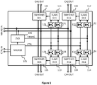
- Figure 2 schematically illustrates an exemplifying lighting controller 200 suitable for example for providing controlled operating power to four dimmable luminaires or luminaire groups. Also other kinds of loads can be coupled to the outputs of the four channels of the lighting controller 200. Displaying four outputs in the example embodiment is not a limiting feature; the same structural and functional solutions are easily generalized to any number of output channels.
- the lighting controller 200 For receiving alternating current the lighting controller 200 comprises an operating power input, which in fig. 2 appears with a reference designator MAINS IN. Switching components 101, 102, 103, 104 are provided at each channel for outputting manipulated half-waves of the alternating current, for example phase-cut alternating current. At each channel a slave processor 211, 212, 213, 214 is configured to control and use the respective switching components.
- the lighting controller 200 comprises a master processor 205 and an internal control bus 206 for conveying, from the master processor 205 to the slave processors 211, 212, 213, 214, control commands indicative of desired type and extent of manipulating that the slave processors should do to the half-waves output from their respective channels.
- control commands indicative of desired type and extent of manipulating that the slave processors should do to the half-waves output from their respective channels.
- the master processor 205 uses the internal control channel 206 to send to the slave processor 211 of the first channel a control command, which the slave processor 211 interprets as an instruction to implement phase cutting of said kind.
- Optoisolators 121, 122, 123, 124 may be provided to galvanically isolate the slave processors 211, 212, 213, 214 from the internal control bus 206, but these are not necessary, if galvanic isolation between channels is not needed in the lighting controller 200.
- the lighting controller 200 does not comprise a separate timing line to the slave processors 211, 212, 213, 214.
- the master processor 205 is configured to time transmissions of control commands on the internal control bus 206 in a predetermined relationship with zero crossing points between half-waves of the alternating current.
- the master processor 205 may become aware of the timing of said zero crossing points for example through a zero voltage detection (ZVD) circuit 207 that is coupled between the AC lines and the master processor 205 within the lighting controller 200.
- ZVD zero voltage detection
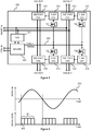
- Fig. 3 illustrates an example embodiment of timing transmissions of control commands in the internal control bus 206 in a predetermined relationship with zero crossing points between half-waves in the alternating current 300.
- the master processor is configured to transmit the control commands on the internal control bus in frames, of which frame 301 is an example.
- Three vertical lines illustrate the location of zero crossing points on the time axis in fig. 3 .
- a predetermined part, here the beginning, of each transmitted frame coincides in time with a zero crossing point between half-waves in the alternating current 300.
- the part of each frame that coincides in time with a zero crossing point could also be the end of the frame, or some reference point between the beginning and the end of the frame.
- FIG. 3 Another example of a feature that is schematically illustrated in fig. 3 is the use of slave-processor-specific time slots.
- the lighting controller has four slave processors, so in a corresponding way each frame in fig. 3 has four slave-processor-specific time slots, of which slot 302 of frame 301 is shown as an example.
- the master processor is configured to transmit control commands to a particular slave processor in a slave-processor-specific time slot of the frames.
- Each slave processor has been programmed to handle a received frame appropriately, so that the slave processor knows to read control commands destined to itself from the correct time slot in the frame, while simultaneously using the predetermined part of the frame - e.g. the beginning - as an indication of the timing of a zero crossing point in the alternating current.
- Fig. 4 illustrates another example embodiment of timing transmissions of control commands in the internal control bus 206 in a predetermined relationship with zero crossing points between half-waves in the alternating current 300.
- the master processor is configured to transmit the control commands on the internal control bus one at a time, so that a predetermined part of each transmitted individual control command coincides in time with a zero crossing point between half-waves in the alternating current.
- An individual control command 401 is shown as an example. It consists of a header part 402 and a payload part 403.
- the master processor inserts a recipient identifier, which tells, to which slave processor the control command is meant.
- the payload part 403 the master processor inserts the actual content of the control command.
- a common feature to the examples shown in figs. 3 and 4 is that the master processor is configured to transmit each frame (in the embodiment of fig. 3 ) or each individual control command (in the embodiment of fig. 4 ) in a time that is shorter than a half-wave in the alternating current 300.
- the embodiment of fig. 3 involves the advantage that a new control command can be transmitted to each slave processor once during each half-wave period.
- the slave processors will use their respective switching components to manipulate the alternating current on a half-wave-wise basis, it is not likely that more frequent delivery of control commands to slave processors than once per half-wave length would be necessary. It is, however, possible to make the transmission of control commands even more frequent, for example so that the master processor transmits a whole frame - with a dedicated time slot for each slave processor - two times, three times or even more frequently during each half-wave period.
- Fig. 5 illustrates an example embodiment that goes towards the other extreme, i.e. transmitting a frame 501 that is longer than a half-wave period in the alternating current.
- a slave-processor-specific time slot 502 is shown as an example.
- the embodiment of fig. 5 involves the advantage of particularly large capacity for transmitting even very long and complicated control commands to the slave processors without requiring the control command transmission and reception arrangements to be capable of very fast signal processing.
- the embodiment of fig. 5 requires programming the slave processors so that they know, how many zero crossing points will occur between the beginnings (or other predetermined parts) of two consecutive frames, so that they can maintain an appropriate time base for switching.
- Fig. 6 illustrates details of an example embodiment in which the master processor 205 digitally filters the ZVD signals.
- the lighting controller comprises a zero voltage detector (ZVD) 207 that is configured to produce an indication signal, like a transition between two digital states, indicating when a zero crossing point occurs between half-waves in the alternating current.
- the master processor 205 is configured to digitally filter a sequence of indication signals produced by the ZVD 207 to produce a digitally filtered zero crossing time base.
- the reason for applying digital filtering is the possible occurrence of jitter in the output of the ZVD 207.
- the alternating current, the zero crossing points of which should be detected should ideally be a smooth, clean sine wave, the zero crossing points of which occur at exactly constant time intervals.
- imperfections in the generation and delivery of mains AC cause the indications of zero crossing points to be generated at more or less irregular intervals.
- Switching in a lighting controller should follow possible slow, long-term variations in the timing of zero-crossing points, so that it does not develop any significant timing bias but remains synchronized with the general rhythm of the half-waves in the alternating current.
- rapid variations in the timing of zero-crossing points (and hence also in the sequence of indication signals output by the ZVD 207) are typically caused by random interference, the effect of which should cancel out in the long term.
- the digital filtering applied by the master processor 205 has the nature of lowpass filtering, and it serves to remove the effect of rapid random variations in the time intervals between consecutive indication signals output by the ZVD 207.
- a digital filtering block 601 is schematically shown in fig. 6 . It takes the sequence of indication signals received from the ZVD 207, performs low pass filtering, and outputs a digitally filtered zero crossing time base.
- control command receiver 602 for receiving control commands through an auxiliary bus
- processing part 603 for interpreting the auxiliary control commands
- command forming part 604 for forming the control commands to be sent to the slave processors
- control command transmitter 605 for transmitting control commands on the internal bus 206.
- control command transmitter 605 is configured to time transmissions of the control commands on said internal control bus in a predetermined relationship with the digitally filtered zero crossing time base that is available at the output of the digital filtering block 601.
- Fig. 7 illustrates schematically some parts of an example of a slave processor 211.
- a control command receiver 701 is configured to receive control commands on the internal control bus 206 of the lighting controller.
- An optoisolator may be employed at the input of the control command receiver 701, but is not separately shown in fig. 7 .
- the handling of received control commands takes place in two branches. In fig.
- the content of the received control commands is interpreted in a part of the slave processor 211 that is schematically illustrated as the processing block 702.
- Switching signals are formed correspondingly in block 706, with their timing synchronized to the time base maintained in block 704, and given to one or more switch driver circuits 707 that perform the actual driving of the MOSFETs or other switches through which the alternating current flows to the output of the corresponding channel.
- Block 703 in fig. 7 and block 601 are basically alternatives to each other, although it is not excluded to divide the digital filtering of the zero crossing indications into two. In that case the master processor would perform coarse filtering and the slave processor would finalize the effect of filtering, including the removal of possible additional jitter that could have been caused by imperfections in timing the transmission of control commands on the internal control bus.
- Fig. 8 illustrates a method for producing phase-cut alternating current in a lighting controller according to an example embodiment.
- Step 801 represents receiving alternating current in the lighting controller.
- Step 802 represents observing zero crossing points in the incoming alternating current
- step 803 represents transmitting control commands from a master processor to a slave processor on an internal control bus of the lighting controller in a predetermined relationship with zero crossing points between half-waves of said alternating current.
- the predetermined relationship means particularly a relationship in time, so that the timing of control commands transmitted on the internal control bus serves as an indication of the timing of detected zero crossing points.
- Step 804 in fig. 8 represents receiving the control commands in a slave processor of the lighting controller.
- Step 805 represents manipulating half-waves of the alternating current under control of the slave processor to produce phase-cut alternating current.
- the slave processor uses content of the control commands to determine the extent of said manipulating, and timing of the control commands on said internal bus to determine the timing of said manipulating.
- Step 806 represents outputting the resulting phase-cut alternating current from the lighting controller.
- the transmission of control commands at step 803 may take place in frames, so that a predetermined part of each transmitted frame coincides in time with a zero crossing point between half-waves in the alternating current.
- control commands to a particular slave processor may be transmitted in a slave-processor-specific time slot of the frames.
- the transmission of control commands at step 803 may take place one at a time, so that a predetermined part of each transmitted individual control command coincides in time with a zero crossing point between half-waves in the alternating current. Irrespective of which of these alternatives is used, each transmission on the internal control bus may be shorter than a half-wave in the alternating current.
- Figs. 9 and 10 show how the method may comprise digitally filtering a sequence of indication signals indicating when zero crossing points occur between half-waves of said alternating current, thus producing a digitally filtered zero crossing time base, and using the digitally filtered zero crossing time base to determine the timing of said manipulating.
- digital filtering 902 takes place in the master processor, between the steps of observing 901 zero crossing points in the incoming alternating current and transmitting 903 control commands from the master processor to the slave processor on the internal control bus.
- the digital filtering at step 902 may imply changes to the other steps; for example, the detection of zero crossing points at step 901 may be originally accomplished at a lower level of accuracy (i.e. with cheaper components) if the filtering at step 902 can be relied upon to remove any resulting jitter.
- digital filtering 1002 takes place in the slave processor between the steps of receiving 1001 control commands from the master processor and manipulating 1003 half-waves of the alternating cur- rent under control of the slave processor to produce phase-cut alternating current.
- Computer programs according to various embodiments can be classified into computer programs of the master processor and computer programs of the slave processor.
- Computer programs of the first kind include one or more sequences of one or more instructions which, when executed by one or more master processors, cause said one or more master processors to transmit to a slave processor a control command, the content of which determines the ex- tent to which said slave processor should manipulate half-waves of an alternating current to produce a phase-cut alternating current, and the timing of which determines the timing of said manipulating.
- They may also comprise one or more sequences of one or more instructions which, when executed by said one or more master processors, cause said one or more master processors to digitally filter a received sequence of indications indicating when zero crossing points occur between half-waves in said alternating current, thus producing a digitally filtered zero crossing time base, and to time transmissions of control commands on said internal control bus in a predetermined relationship with said digitally filtered zero crossing time base.
- Computer programs of the slave processor include one or more sequences of one or more instructions which, when executed by one or more slave processors, cause said one or more slave processors to use content of control commands received on an internal control bus of the lighting controller to deter- mine the extent of manipulating half-waves of an alternating current to produce a phase-cut alternating current, and to use timing of said control commands on said internal bus to determine the timing of said manipulating.
- references to a processor should not be understood to encompass only programmable processors, but also dedicated circuits such as field-programmable gate arrays (FPGA), application specific circuits (ASIC), signal processors, etc.
- FPGA field-programmable gate arrays
- ASIC application specific circuits
- signal processors etc.
Landscapes
- Circuit Arrangement For Electric Light Sources In General (AREA)
Claims (15)
- Beleuchtungssteuerungseinheit (200) zum Steuern einer oder mehrerer Lichtquellen, die mit entsprechenden Ausgängen der Beleuchtungssteuerungseinheit gekoppelt sind, wobei die Beleuchtungssteuerungseinheit umfasst:einen Betriebsenergieeingang zum Aufnehmen von Wechselstrom,einen Master-Prozessor (205),einen oder mehrere Slave-Prozessoren (211, 212, 213, 214), wobei jeder Slave-Prozessor eingerichtet ist, entsprechende Schaltkomponenten (101, 102, 103, 104) zu verwenden, um Halbwellen des Wechselstroms zu manipulieren, einen phasengeschnittenen Wechselstrom an einem entsprechenden derjeweiligen Ausgänge der Beleuchtungssteuerungseinheit (200) auszugeben, undeinen internen Steuerungsbus (206) zum Weiterleiten von Steuerungsbefehlen, die ein gewünschtes Ausmaß des Manipulierens anzeigen, von dem Master-Prozessor zu dem einen oder den mehreren Slave-Prozessoren;dadurch gekennzeichnet, dass der Master-Prozessor (205) eingerichtet ist, ferner Timing-Informationen an den einen oder die mehreren Slave-Prozessoren (211, 212, 213, 214) weiterzuleiten durch Timen von Übertragungen (301, 401, 501) der Steuerungsbefehle auf dem internen Steuerungsbus (206) in einer vorherbestimmten Beziehung mit Nulldurchgangspunkten zwischen Halbwellen des Wechselstroms (300).
- Beleuchtungssteuerungseinheit nach Anspruch 1, wobei der Master-Prozessor (205) eingerichtet ist, die Steuerungsbefehle auf dem internen Steuerungsbus in Frames (301, 501) zu übertragen, so dass ein vorherbestimmter Teil jedes übertragenen Frames mit einem Nulldurchgangspunkt zwischen Halbwellen im Wechselstrom (300) zeitlich zusammenfällt.
- Beleuchtungssteuerungseinheit nach Anspruch 2, wobei der Master-Prozessor (205) eingerichtet ist, Steuerungsbefehle an einen bestimmten Slave-Prozessor (211, 212, 213, 214) in einem Slave-Prozessor-spezifischen Zeitschlitz (302, 502) der Frames (301, 501) zu übertragen.
- Beleuchtungssteuerungseinheit nach Anspruch 1, wobei der Master-Prozessor (205) eingerichtet ist, die Steuerungsbefehle auf dem internen Steuerungsbus nacheinander zu übertragen, so dass ein vorherbestimmter Teil jedes übertragenen einzelnen Steuerungsbefehls (401) mit einem Nulldurchgangspunkt zwischen Halbwellen im Wechselstrom (300) zeitlich zusammenfällt.
- Beleuchtungssteuerungseinheit nach einem der Ansprüche 1 bis 4, wobei:
der Master-Prozessor (205) eingerichtet ist, jeden Frame (301) oder jeden einzelnen Steuerungsbefehl (401) in einer Zeit zu übertragen, die kürzer ist als eine Halbwelle in dem Wechselstrom (300). - Beleuchtungssteuerungseinheit nach einem der Ansprüche 1 bis 5, wobei:die Beleuchtungssteuerungseinheit einen Nullspannungsdetektor (207) umfasst, der eingerichtet ist, ein Anzeigesignal zu erzeugen, das anzeigt, wann ein Nulldurchgangspunkt zwischen Halbwellen in dem Wechselstrom (300) auftritt,der Master-Prozessor (205) eingerichtet ist, eine Folge von Anzeigesignalen, die von dem Nullspannungsdetektor (207) erzeugt werden, digital zu filtern (601), um eine digital gefilterte Nulldurchgang-Zeitbasis zu erzeugen, undder Master-Prozessor (205) eingerichtet ist, Übertragungen (301, 401, 501) der Steuerungsbefehle auf dem internen Steuerungsbus (206) in einer vorherbestimmten Beziehung mit der digital gefilterten Nulldurchgang-Zeitbasis zu timen.
- Verfahren zum Erzeugen von phasengeschnittenem Wechselstrom in einer Beleuchtungssteuerungseinheit, umfassend:Beobachten (802, 901) von Nulldurchgangspunkten in ankommendem Wechselstrom,dadurch gekennzeichnet, dass das Verfahren umfasst:Übertragen (802, 901) von Steuerungsbefehlen von einem Master-Prozessor (205) zu einem Slave-Prozessor (211, 212, 213, 214) auf einem internen Steuerungsbus (206) der Beleuchtungssteuerungseinheit (200) in einer vorherbestimmten Beziehung zu Nulldurchgangspunkten zwischen Halbwellen des Wechselstroms (300), undManipulieren (805) von Halbwellen des Wechselstroms unter Steuerung des Slave-Prozessors (211, 212, 213, 214), um den phasengeschnittenen Wechselstrom zu erzeugen, mit Verwenden des Inhalts der Steuerungsbefehle, um das Ausmaß des Manipulierens zu bestimmen, und mit Verwenden des Timings der Steuerungsbefehle auf dem internen Bus (206), um das Timing des Manipulierens zu bestimmen.
- Verfahren nach Anspruch 7, wobei die Steuerungsbefehle auf dem internen Steuerungsbus (206) in Frames (301, 501) übertragen werden, so dass ein vorherbestimmter Teil jedes übertragenen Frames mit einem Nulldurchgangspunkt zwischen Halbwellen in dem Wechselstrom (300) zeitlich zusammenfällt.
- Verfahren nach Anspruch 8, wobei Steuerungsbefehle an einen bestimmten Slave-Prozessor (211, 212, 213, 214) in einem Slave-Prozessor-spezifischen Zeitschlitz (302, 502) der Frames übertragen werden.
- Verfahren nach Anspruch 7, wobei die Steuerungsbefehle auf dem internen Steuerungsbus (206) nacheinander übertragen werden, so dass ein vorherbestimmter Teil jedes übertragenen einzelnen Steuerungsbefehls (401) mit einem Nulldurchgangspunkt zwischen Halbwellen in dem Wechselstrom (300) zeitlich zusammenfällt.
- Verfahren nach einem der Ansprüche 7 bis 10, wobei jede Übertragung (301, 401) auf dem internen Steuerungsbus (206) kürzer ist als eine Halbwelle in dem Wechselstrom (300).
- Beleuchtungssteuerungseinheit nach einem der Ansprüche 7 bis 11, umfassend:digitales Filtern (902, 1002) einer Folge von Anzeigesignalen, die anzeigen, wann Nulldurchgangspunkte zwischen Halbwellen des Wechselstroms (300) auftreten, dadurch Erzeugen einer digital gefilterte Nulldurchgang-Zeitbasis, undVerwenden der digital gefilterten Nulldurchgang-Zeitbasis, um das Timing des Manipulierens zu bestimmen.
- Computerprogramm zum Übertragen von Steuerungsbefehlen von einem Master-Prozessor (205) zu einem Slave-Prozessor (211, 212, 213, 214) auf einem internen Steuerungsbus (206) einer Beleuchtungssteuerungseinheit (200), wobei das Computerprogramm eine oder mehrere Folgen von einer oder mehreren Anweisungen enthält, die, bei Ausführung durch den Master-Prozessor (205), den Master-Prozessor (205) veranlassen, an den Slave-Prozessor (211, 212, 213, 214) einen Steuerungsbefehl zu übertragen, dessen Inhalt das Ausmaß bestimmt, in dem der Slave-Prozessor (211, 212, 213, 214) Halbwellen eines Wechselstroms manipulieren sollte, um einen phasengeschnittenen Wechselstrom zu erzeugen, und dessen Timing in Bezug auf Nulldurchgangspunkte zwischen den Halbwellen des Wechselstroms (300) das Timing des Manipulierens bestimmt.
- Computerprogramm nach Anspruch 13, umfassend eine oder mehrere Folgen von einer oder mehreren Anweisungen, die, bei Ausführung durch den Master-Prozessor (205), den Hauptprozessor (205) veranlassen:eine empfangene Folge von Anzeigen, die anzeigen, wann Nulldurchgangspunkte zwischen Halbwellen in dem Wechselstrom auftreten, digital zu filtern (902), wodurch eine digital gefilterte Nulldurchgang-Zeitbasis erzeugt wird, undÜbertragungen (301, 401, 501) des Steuerungsbefehls auf dem internen Steuerungsbus (206) in einer vorbestimmten Beziehung mit der digital gefilterten Nulldurchgang-Zeitbasis zu timen.
- Computerprogramm zum Manipulieren von Halbwellen von Wechselstrom unter Steuerung eines oder mehrerer Slave-Prozessoren (211, 212, 213, 214), um phasengeschnittenen Wechselstrom in einer Beleuchtungssteuerungseinheit (200) zu erzeugen, wobei das Computerprogramm eine oder mehrere Folgen von einer oder mehreren Anweisungen enthält, die, bei Ausführung durch den einen oder die mehreren Slave-Prozessoren (211, 212, 213, 214), den einen oder die mehreren Slave-Prozessoren veranlassen, den Inhalt von Steuerungsbefehlen zu verwenden, die auf einem internen Steuerungsbus (206) der Beleuchtungssteuerungseinheit (200) empfangen werden, um das Ausmaß des Manipulierens zu bestimmen und ein Timing der Steuerungsbefehle auf dem internen Bus in Bezug auf Nulldurchgangspunkte zwischen Halbwellen des Wechselstroms (300) zu verwenden, um das Timing des Manipulierens zu bestimmen.
Priority Applications (1)
| Application Number | Priority Date | Filing Date | Title |
|---|---|---|---|
| EP14162186.2A EP2925095B1 (de) | 2014-03-28 | 2014-03-28 | Beleuchtungssteuerung |
Applications Claiming Priority (1)
| Application Number | Priority Date | Filing Date | Title |
|---|---|---|---|
| EP14162186.2A EP2925095B1 (de) | 2014-03-28 | 2014-03-28 | Beleuchtungssteuerung |
Publications (2)
| Publication Number | Publication Date |
|---|---|
| EP2925095A1 EP2925095A1 (de) | 2015-09-30 |
| EP2925095B1 true EP2925095B1 (de) | 2020-09-23 |
Family
ID=50382356
Family Applications (1)
| Application Number | Title | Priority Date | Filing Date |
|---|---|---|---|
| EP14162186.2A Active EP2925095B1 (de) | 2014-03-28 | 2014-03-28 | Beleuchtungssteuerung |
Country Status (1)
| Country | Link |
|---|---|
| EP (1) | EP2925095B1 (de) |
Families Citing this family (3)
| Publication number | Priority date | Publication date | Assignee | Title |
|---|---|---|---|---|
| DE102017213888B3 (de) * | 2017-08-09 | 2018-10-31 | Siemens Schweiz Ag | Dimmer |
| DE102017215643B3 (de) | 2017-09-06 | 2018-07-26 | Siemens Schweiz Ag | Dimmersystem und Verfahren zur Steuerung der Leistungsaufnahme einer an ein Dimmersystem anschliessbaren Last |
| DE102018009924B4 (de) * | 2018-12-17 | 2020-10-01 | Siemens Schweiz Ag | Dimmer und Verfahren zum Erkennen der korrekten Verdrahtung von Dimmkanälen |
Family Cites Families (5)
| Publication number | Priority date | Publication date | Assignee | Title |
|---|---|---|---|---|
| JPH02256193A (ja) * | 1989-03-29 | 1990-10-16 | Toshiba Lighting & Technol Corp | 照明制御装置 |
| US5825135A (en) * | 1997-03-10 | 1998-10-20 | Chang; Chin-Hsiung | Halogen lamp control circuit assembly |
| RU2630220C2 (ru) * | 2011-10-25 | 2017-09-06 | Филипс Лайтинг Холдинг Б.В. | Способы и устройство для управления осветительным прибором, использующие протокол связи |
| ITMC20120006A1 (it) * | 2012-01-26 | 2013-07-27 | Si Gi Impianti Elettrici Di Silenz I Gianluca E S | Sistema di luci ad effetti sincronizzati. |
| WO2013175810A1 (ja) * | 2012-05-25 | 2013-11-28 | 株式会社吉川アールエフセミコン | 電力線通信システム |
-
2014
- 2014-03-28 EP EP14162186.2A patent/EP2925095B1/de active Active
Non-Patent Citations (1)
| Title |
|---|
| None * |
Also Published As
| Publication number | Publication date |
|---|---|
| EP2925095A1 (de) | 2015-09-30 |
Similar Documents
| Publication | Publication Date | Title |
|---|---|---|
| EP3399846B1 (de) | Stromleitungskommunikationssteuerung von beleuchtungsarmaturen mit leuchtdioden (leds) | |
| CA2800726C (en) | Dimming protocol detection for a light fixture | |
| US9072134B2 (en) | Configurable lighting devices under broadcast control | |
| AU2015202557B2 (en) | Illumination Regulating System in Synchronization with AC Power Frequency and Method Using the Same | |
| US10470263B2 (en) | Dimmable lighting systems and methods of dimming lighting systems | |
| JP6239689B2 (ja) | 給電制御システムおよび方法 | |
| US8324833B2 (en) | Light color tunability | |
| EP2925095B1 (de) | Beleuchtungssteuerung | |
| US9668326B2 (en) | Light fixture with multiple dimming capabilities | |
| KR101456928B1 (ko) | 전력선 기반 조명장치의 디밍 제어 장치 | |
| US11277894B2 (en) | Universal adapter for lighting system for indoor grow application | |
| CN105813258A (zh) | 一种led电源用单根导线同步的同步方法 | |
| US9854649B2 (en) | Operating device for lamps for transmitting information | |
| CN103874278A (zh) | 发光驱动装置及其驱动方法 | |
| US9089012B2 (en) | Secondary-side sensing of phase-dimming signal | |
| WO2012009622A2 (en) | Powerline communication control of light emitting diode (led) lighting fixtures | |
| AU2014373614B2 (en) | DALI control system and method | |
| FI128227B (en) | Method and arrangement for flexible dimming control of lighting drivers |
Legal Events
| Date | Code | Title | Description |
|---|---|---|---|
| PUAI | Public reference made under article 153(3) epc to a published international application that has entered the european phase |
Free format text: ORIGINAL CODE: 0009012 |
|
| AK | Designated contracting states |
Kind code of ref document: A1 Designated state(s): AL AT BE BG CH CY CZ DE DK EE ES FI FR GB GR HR HU IE IS IT LI LT LU LV MC MK MT NL NO PL PT RO RS SE SI SK SM TR |
|
| AX | Request for extension of the european patent |
Extension state: BA ME |
|
| 17P | Request for examination filed |
Effective date: 20160330 |
|
| RBV | Designated contracting states (corrected) |
Designated state(s): AL AT BE BG CH CY CZ DE DK EE ES FI FR GB GR HR HU IE IS IT LI LT LU LV MC MK MT NL NO PL PT RO RS SE SI SK SM TR |
|
| STAA | Information on the status of an ep patent application or granted ep patent |
Free format text: STATUS: EXAMINATION IS IN PROGRESS |
|
| 17Q | First examination report despatched |
Effective date: 20190524 |
|
| GRAP | Despatch of communication of intention to grant a patent |
Free format text: ORIGINAL CODE: EPIDOSNIGR1 |
|
| STAA | Information on the status of an ep patent application or granted ep patent |
Free format text: STATUS: GRANT OF PATENT IS INTENDED |
|
| INTG | Intention to grant announced |
Effective date: 20191218 |
|
| GRAJ | Information related to disapproval of communication of intention to grant by the applicant or resumption of examination proceedings by the epo deleted |
Free format text: ORIGINAL CODE: EPIDOSDIGR1 |
|
| STAA | Information on the status of an ep patent application or granted ep patent |
Free format text: STATUS: EXAMINATION IS IN PROGRESS |
|
| REG | Reference to a national code |
Ref country code: DE Ref legal event code: R079 Ref document number: 602014070405 Country of ref document: DE Free format text: PREVIOUS MAIN CLASS: H05B0037020000 Ipc: H05B0047180000 |
|
| GRAP | Despatch of communication of intention to grant a patent |
Free format text: ORIGINAL CODE: EPIDOSNIGR1 |
|
| STAA | Information on the status of an ep patent application or granted ep patent |
Free format text: STATUS: GRANT OF PATENT IS INTENDED |
|
| INTC | Intention to grant announced (deleted) | ||
| RIC1 | Information provided on ipc code assigned before grant |
Ipc: H05B 47/18 20200101AFI20200414BHEP |
|
| INTG | Intention to grant announced |
Effective date: 20200429 |
|
| GRAS | Grant fee paid |
Free format text: ORIGINAL CODE: EPIDOSNIGR3 |
|
| GRAA | (expected) grant |
Free format text: ORIGINAL CODE: 0009210 |
|
| STAA | Information on the status of an ep patent application or granted ep patent |
Free format text: STATUS: THE PATENT HAS BEEN GRANTED |
|
| AK | Designated contracting states |
Kind code of ref document: B1 Designated state(s): AL AT BE BG CH CY CZ DE DK EE ES FI FR GB GR HR HU IE IS IT LI LT LU LV MC MK MT NL NO PL PT RO RS SE SI SK SM TR |
|
| RAP1 | Party data changed (applicant data changed or rights of an application transferred) |
Owner name: HELVAR OY AB |
|
| REG | Reference to a national code |
Ref country code: GB Ref legal event code: FG4D |
|
| REG | Reference to a national code |
Ref country code: CH Ref legal event code: EP |
|
| REG | Reference to a national code |
Ref country code: DE Ref legal event code: R096 Ref document number: 602014070405 Country of ref document: DE |
|
| REG | Reference to a national code |
Ref country code: IE Ref legal event code: FG4D |
|
| REG | Reference to a national code |
Ref country code: AT Ref legal event code: REF Ref document number: 1317757 Country of ref document: AT Kind code of ref document: T Effective date: 20201015 |
|
| PG25 | Lapsed in a contracting state [announced via postgrant information from national office to epo] |
Ref country code: FI Free format text: LAPSE BECAUSE OF FAILURE TO SUBMIT A TRANSLATION OF THE DESCRIPTION OR TO PAY THE FEE WITHIN THE PRESCRIBED TIME-LIMIT Effective date: 20200923 Ref country code: GR Free format text: LAPSE BECAUSE OF FAILURE TO SUBMIT A TRANSLATION OF THE DESCRIPTION OR TO PAY THE FEE WITHIN THE PRESCRIBED TIME-LIMIT Effective date: 20201224 Ref country code: NO Free format text: LAPSE BECAUSE OF FAILURE TO SUBMIT A TRANSLATION OF THE DESCRIPTION OR TO PAY THE FEE WITHIN THE PRESCRIBED TIME-LIMIT Effective date: 20201223 Ref country code: HR Free format text: LAPSE BECAUSE OF FAILURE TO SUBMIT A TRANSLATION OF THE DESCRIPTION OR TO PAY THE FEE WITHIN THE PRESCRIBED TIME-LIMIT Effective date: 20200923 Ref country code: BG Free format text: LAPSE BECAUSE OF FAILURE TO SUBMIT A TRANSLATION OF THE DESCRIPTION OR TO PAY THE FEE WITHIN THE PRESCRIBED TIME-LIMIT Effective date: 20201223 Ref country code: SE Free format text: LAPSE BECAUSE OF FAILURE TO SUBMIT A TRANSLATION OF THE DESCRIPTION OR TO PAY THE FEE WITHIN THE PRESCRIBED TIME-LIMIT Effective date: 20200923 |
|
| REG | Reference to a national code |
Ref country code: AT Ref legal event code: MK05 Ref document number: 1317757 Country of ref document: AT Kind code of ref document: T Effective date: 20200923 |
|
| PG25 | Lapsed in a contracting state [announced via postgrant information from national office to epo] |
Ref country code: LV Free format text: LAPSE BECAUSE OF FAILURE TO SUBMIT A TRANSLATION OF THE DESCRIPTION OR TO PAY THE FEE WITHIN THE PRESCRIBED TIME-LIMIT Effective date: 20200923 Ref country code: RS Free format text: LAPSE BECAUSE OF FAILURE TO SUBMIT A TRANSLATION OF THE DESCRIPTION OR TO PAY THE FEE WITHIN THE PRESCRIBED TIME-LIMIT Effective date: 20200923 |
|
| REG | Reference to a national code |
Ref country code: NL Ref legal event code: MP Effective date: 20200923 |
|
| REG | Reference to a national code |
Ref country code: LT Ref legal event code: MG4D |
|
| PG25 | Lapsed in a contracting state [announced via postgrant information from national office to epo] |
Ref country code: EE Free format text: LAPSE BECAUSE OF FAILURE TO SUBMIT A TRANSLATION OF THE DESCRIPTION OR TO PAY THE FEE WITHIN THE PRESCRIBED TIME-LIMIT Effective date: 20200923 Ref country code: CZ Free format text: LAPSE BECAUSE OF FAILURE TO SUBMIT A TRANSLATION OF THE DESCRIPTION OR TO PAY THE FEE WITHIN THE PRESCRIBED TIME-LIMIT Effective date: 20200923 Ref country code: PT Free format text: LAPSE BECAUSE OF FAILURE TO SUBMIT A TRANSLATION OF THE DESCRIPTION OR TO PAY THE FEE WITHIN THE PRESCRIBED TIME-LIMIT Effective date: 20210125 Ref country code: LT Free format text: LAPSE BECAUSE OF FAILURE TO SUBMIT A TRANSLATION OF THE DESCRIPTION OR TO PAY THE FEE WITHIN THE PRESCRIBED TIME-LIMIT Effective date: 20200923 Ref country code: NL Free format text: LAPSE BECAUSE OF FAILURE TO SUBMIT A TRANSLATION OF THE DESCRIPTION OR TO PAY THE FEE WITHIN THE PRESCRIBED TIME-LIMIT Effective date: 20200923 Ref country code: SM Free format text: LAPSE BECAUSE OF FAILURE TO SUBMIT A TRANSLATION OF THE DESCRIPTION OR TO PAY THE FEE WITHIN THE PRESCRIBED TIME-LIMIT Effective date: 20200923 Ref country code: RO Free format text: LAPSE BECAUSE OF FAILURE TO SUBMIT A TRANSLATION OF THE DESCRIPTION OR TO PAY THE FEE WITHIN THE PRESCRIBED TIME-LIMIT Effective date: 20200923 |
|
| PG25 | Lapsed in a contracting state [announced via postgrant information from national office to epo] |
Ref country code: IS Free format text: LAPSE BECAUSE OF FAILURE TO SUBMIT A TRANSLATION OF THE DESCRIPTION OR TO PAY THE FEE WITHIN THE PRESCRIBED TIME-LIMIT Effective date: 20210123 Ref country code: PL Free format text: LAPSE BECAUSE OF FAILURE TO SUBMIT A TRANSLATION OF THE DESCRIPTION OR TO PAY THE FEE WITHIN THE PRESCRIBED TIME-LIMIT Effective date: 20200923 Ref country code: ES Free format text: LAPSE BECAUSE OF FAILURE TO SUBMIT A TRANSLATION OF THE DESCRIPTION OR TO PAY THE FEE WITHIN THE PRESCRIBED TIME-LIMIT Effective date: 20200923 Ref country code: AT Free format text: LAPSE BECAUSE OF FAILURE TO SUBMIT A TRANSLATION OF THE DESCRIPTION OR TO PAY THE FEE WITHIN THE PRESCRIBED TIME-LIMIT Effective date: 20200923 Ref country code: AL Free format text: LAPSE BECAUSE OF FAILURE TO SUBMIT A TRANSLATION OF THE DESCRIPTION OR TO PAY THE FEE WITHIN THE PRESCRIBED TIME-LIMIT Effective date: 20200923 |
|
| REG | Reference to a national code |
Ref country code: DE Ref legal event code: R097 Ref document number: 602014070405 Country of ref document: DE |
|
| PG25 | Lapsed in a contracting state [announced via postgrant information from national office to epo] |
Ref country code: SK Free format text: LAPSE BECAUSE OF FAILURE TO SUBMIT A TRANSLATION OF THE DESCRIPTION OR TO PAY THE FEE WITHIN THE PRESCRIBED TIME-LIMIT Effective date: 20200923 |
|
| PLBE | No opposition filed within time limit |
Free format text: ORIGINAL CODE: 0009261 |
|
| STAA | Information on the status of an ep patent application or granted ep patent |
Free format text: STATUS: NO OPPOSITION FILED WITHIN TIME LIMIT |
|
| PG25 | Lapsed in a contracting state [announced via postgrant information from national office to epo] |
Ref country code: SI Free format text: LAPSE BECAUSE OF FAILURE TO SUBMIT A TRANSLATION OF THE DESCRIPTION OR TO PAY THE FEE WITHIN THE PRESCRIBED TIME-LIMIT Effective date: 20200923 Ref country code: DK Free format text: LAPSE BECAUSE OF FAILURE TO SUBMIT A TRANSLATION OF THE DESCRIPTION OR TO PAY THE FEE WITHIN THE PRESCRIBED TIME-LIMIT Effective date: 20200923 |
|
| 26N | No opposition filed |
Effective date: 20210624 |
|
| PG25 | Lapsed in a contracting state [announced via postgrant information from national office to epo] |
Ref country code: MC Free format text: LAPSE BECAUSE OF FAILURE TO SUBMIT A TRANSLATION OF THE DESCRIPTION OR TO PAY THE FEE WITHIN THE PRESCRIBED TIME-LIMIT Effective date: 20200923 Ref country code: IT Free format text: LAPSE BECAUSE OF FAILURE TO SUBMIT A TRANSLATION OF THE DESCRIPTION OR TO PAY THE FEE WITHIN THE PRESCRIBED TIME-LIMIT Effective date: 20200923 |
|
| REG | Reference to a national code |
Ref country code: CH Ref legal event code: PL |
|
| REG | Reference to a national code |
Ref country code: BE Ref legal event code: MM Effective date: 20210331 |
|
| PG25 | Lapsed in a contracting state [announced via postgrant information from national office to epo] |
Ref country code: LU Free format text: LAPSE BECAUSE OF NON-PAYMENT OF DUE FEES Effective date: 20210328 Ref country code: LI Free format text: LAPSE BECAUSE OF NON-PAYMENT OF DUE FEES Effective date: 20210331 Ref country code: CH Free format text: LAPSE BECAUSE OF NON-PAYMENT OF DUE FEES Effective date: 20210331 Ref country code: FR Free format text: LAPSE BECAUSE OF NON-PAYMENT OF DUE FEES Effective date: 20210331 Ref country code: IE Free format text: LAPSE BECAUSE OF NON-PAYMENT OF DUE FEES Effective date: 20210328 |
|
| PG25 | Lapsed in a contracting state [announced via postgrant information from national office to epo] |
Ref country code: BE Free format text: LAPSE BECAUSE OF NON-PAYMENT OF DUE FEES Effective date: 20210331 |
|
| PG25 | Lapsed in a contracting state [announced via postgrant information from national office to epo] |
Ref country code: HU Free format text: LAPSE BECAUSE OF FAILURE TO SUBMIT A TRANSLATION OF THE DESCRIPTION OR TO PAY THE FEE WITHIN THE PRESCRIBED TIME-LIMIT; INVALID AB INITIO Effective date: 20140328 |
|
| PG25 | Lapsed in a contracting state [announced via postgrant information from national office to epo] |
Ref country code: CY Free format text: LAPSE BECAUSE OF FAILURE TO SUBMIT A TRANSLATION OF THE DESCRIPTION OR TO PAY THE FEE WITHIN THE PRESCRIBED TIME-LIMIT Effective date: 20200923 |
|
| PG25 | Lapsed in a contracting state [announced via postgrant information from national office to epo] |
Ref country code: MK Free format text: LAPSE BECAUSE OF FAILURE TO SUBMIT A TRANSLATION OF THE DESCRIPTION OR TO PAY THE FEE WITHIN THE PRESCRIBED TIME-LIMIT Effective date: 20200923 |
|
| PG25 | Lapsed in a contracting state [announced via postgrant information from national office to epo] |
Ref country code: MT Free format text: LAPSE BECAUSE OF FAILURE TO SUBMIT A TRANSLATION OF THE DESCRIPTION OR TO PAY THE FEE WITHIN THE PRESCRIBED TIME-LIMIT Effective date: 20200923 |
|
| PG25 | Lapsed in a contracting state [announced via postgrant information from national office to epo] |
Ref country code: TR Free format text: LAPSE BECAUSE OF FAILURE TO SUBMIT A TRANSLATION OF THE DESCRIPTION OR TO PAY THE FEE WITHIN THE PRESCRIBED TIME-LIMIT Effective date: 20200923 |
|
| PGFP | Annual fee paid to national office [announced via postgrant information from national office to epo] |
Ref country code: GB Payment date: 20260327 Year of fee payment: 13 |
|
| PGFP | Annual fee paid to national office [announced via postgrant information from national office to epo] |
Ref country code: DE Payment date: 20260327 Year of fee payment: 13 |