EP2925116B1 - Appareil de traitement de récolte dans une moissonneuse-batteuse - Google Patents
Appareil de traitement de récolte dans une moissonneuse-batteuse Download PDFInfo
- Publication number
- EP2925116B1 EP2925116B1 EP13792033.6A EP13792033A EP2925116B1 EP 2925116 B1 EP2925116 B1 EP 2925116B1 EP 13792033 A EP13792033 A EP 13792033A EP 2925116 B1 EP2925116 B1 EP 2925116B1
- Authority
- EP
- European Patent Office
- Prior art keywords
- grain
- pan
- fan
- combine harvester
- cleaning
- Prior art date
- Legal status (The legal status is an assumption and is not a legal conclusion. Google has not performed a legal analysis and makes no representation as to the accuracy of the status listed.)
- Active
Links
Images




Classifications
-
- A—HUMAN NECESSITIES
- A01—AGRICULTURE; FORESTRY; ANIMAL HUSBANDRY; HUNTING; TRAPPING; FISHING
- A01F—PROCESSING OF HARVESTED PRODUCE; HAY OR STRAW PRESSES; DEVICES FOR STORING AGRICULTURAL OR HORTICULTURAL PRODUCE
- A01F12/00—Parts or details of threshing apparatus
- A01F12/44—Grain cleaners; Grain separators
- A01F12/444—Fanning means
-
- A—HUMAN NECESSITIES
- A01—AGRICULTURE; FORESTRY; ANIMAL HUSBANDRY; HUNTING; TRAPPING; FISHING
- A01F—PROCESSING OF HARVESTED PRODUCE; HAY OR STRAW PRESSES; DEVICES FOR STORING AGRICULTURAL OR HORTICULTURAL PRODUCE
- A01F12/00—Parts or details of threshing apparatus
- A01F12/44—Grain cleaners; Grain separators
- A01F12/446—Sieving means
- A01F12/448—Sieve adjusting means
-
- A—HUMAN NECESSITIES
- A01—AGRICULTURE; FORESTRY; ANIMAL HUSBANDRY; HUNTING; TRAPPING; FISHING
- A01F—PROCESSING OF HARVESTED PRODUCE; HAY OR STRAW PRESSES; DEVICES FOR STORING AGRICULTURAL OR HORTICULTURAL PRODUCE
- A01F12/00—Parts or details of threshing apparatus
- A01F12/48—Air conduits or blowers for grain
-
- A—HUMAN NECESSITIES
- A01—AGRICULTURE; FORESTRY; ANIMAL HUSBANDRY; HUNTING; TRAPPING; FISHING
- A01F—PROCESSING OF HARVESTED PRODUCE; HAY OR STRAW PRESSES; DEVICES FOR STORING AGRICULTURAL OR HORTICULTURAL PRODUCE
- A01F7/00—Threshing apparatus
- A01F7/02—Threshing apparatus with rotating tools
- A01F7/04—Threshing apparatus with rotating tools with axles transverse to the feeding direction
Definitions
- the invention relates to the processing of a crop stream in a combine harvester and more particularly to the processing and cleaning of grain separated by threshing apparatus.
- self-propelled combine harvesters have been used by farmers to harvest a wide range of crops including cereals, maize and oil-seed rape.
- a combine harvester cuts the crop material, threshes the grain therefrom, separates the grain from the straw, and cleans the grain before storing in an on-board tank. Straw and crop residue is ejected from the rear of the machine.
- Threshing is typically carried out by one or more threshing cylinders which rotate within a drum or cage.
- Combines of the conventional or hybrid threshing type comprise a threshing cylinder which rotates on a transverse axis wherein the crop material passes tangentially under the cylinder.
- An axial-type threshing system includes one or more rotors having longitudinally-aligned rotation axes wherein the crop material is fed into a front end and is conveyed in a spiral path around the rotors.
- Combines having a transverse threshing system include a threshing cylinder having a transverse rotation axis wherein the crop material is fed tangentially at one side and is conveyed in a spiral path around the rotor across the width of the machine.
- Grain and chaff separated in the threshing process falls under gravity through a grate onto an underlying conveyance system that passes the grain and chaff to a cleaning unit.
- the conveyance system typically includes a grain pan which is driven in an oscillating manner to convey the grain and chaff rearwardly to a rear edge from where the grain and chaff falls under gravity into the cleaning unit (often termed cleaning shoe').
- the separating apparatus typically includes a plurality of straw walkers which 'walk' the straw over a grate to the rear of the machine while the separated grain falls through the grate.
- the separating apparatus comprises an extension of the one or more axial rotors wherein the separated material falls through a grate provided by the rotor cages.
- the material falling through the grates of the separating apparatus is caught by an underlying separator pan (or 'return pan') which is also driven in an oscillating manner to convey the material forwardly to a front edge from where it falls under gravity to combine with the grain collected from the threshing apparatus.
- the straw by-product from the separating apparatus is ejected from the rear of the combine.
- the cleaning unit of most combines operates according to a well-established process in which grain and chaff cascading down from the thresher and separator pans is subjected to an airstream created by a fan.
- the airstream blows the lighter chaff and dust rearwardly and out of the combine whilst the heavier grain falls onto and through a chaffer and one or more cleaning sieves before being conveyed to the grain tank.
- the speed of the airflow is chosen so as to maximise the percentage of chaff, and indeed any material other than grain (MOG), removed from the crop-stream whilst minimising the percentage grain loss from the rear of the machine.
- EP 0 077 416 A1 discloses a grain pan for harvesters; DE 3 283 326 A1 discloses a self-propelled combine harvester with a threshing device; EP 0 683 970 A2 discloses a blowing cleaning device for a threshing machine.
- a combine harvester comprising threshing apparatus, a grain pan and a cleaning unit, the grain pan arranged to catch a grain/chaff stream falling under gravity from the threshing apparatus and being driven in an oscillating manner to convey the collected grain/chaff stream rearwardly to a rear edge from where the grain/chaff stream falls under gravity into the cleaning unit, the cleaning unit comprising a fan unit with a fan housing for generating a first cleaning airstream which is directed under the grain pan and through the grain/chaff stream falling from said rear edge, characterised in that the combine harvester further comprises: a pair of secondary ducts able to pass air from a pair of subsidiary vents in the fan housing up and around the sides of the grain pan, and into respective ends of a transverse air nozzle secured to the underside of a separator pan and including at least one rearward-directed vent in the form of a slot, said vent located above, and spaced from, the grain to direct a second cleaning airstream (Y) above the grain
- the grain/MOG mixture is effectively pre-cleaned wherein lighter MOG is blown rearwardly as the material falls under gravity on its journey from the threshing/separating apparatus to the cleaning unit.
- the invention involves the recognition that the crop material conveyed rearwardly along the grain pan stratifies to a certain extent wherein the heavier grain settles into a lower layer adjacent the grain pan whilst the lighter/larger MOG rises to the top.
- a second cleaning air stream injected above the grain pan affects only the top layer of MOG whereas the bottom layer of grain is shielded and, therefore, has a greater opportunity to settle on a chaffer (course sieve) of a downstream cleaning unit.
- the terms “grain pan”, “thresher pan” and “stratification pan” shall be used interchangeably in the description hereinafter and shall refer to an oscillating pan which catches grain and MOG from threshing and/or separating apparatus disposed above.
- the terms “return pan” and “separator pan” shall be used interchangeably and will refer to a pan which catches material from separating apparatus disposed above and conveys the material in a forward direction.
- the second cleaning air stream may be generated by a number of different means.
- the fan unit preferably generates the second cleaning air stream by a modified construction.
- the fan unit may comprise a plurality of impeller blades mounted to a transverse orientated fan shaft and which rotates within a fan housing located under the grain pan, and wherein a first duct conveys the first cleaning air stream from a central portion of the fan housing under the rear edge of the grain pan.
- the first cleaning air stream is therefore passed through the cleaning shoe both above and below the chaffer so as to propel MOG rearwardly towards the rear edges of the chaffer.
- the impeller blades and fan housing are extended beyond the width of the grain pan, and at least one further duct conveys the second cleaning air stream from an end region of the fan housing around the grain pan.
- the existing fan is extended transversely and additional ducts are provided at each radial end region to collect the second cleaning air stream and direct it to a nozzle or otherwise disposed above the grain pan.
- each additional fan has a housing and set of impellers separate from those of the main fan.
- Each additional fan may comprise impeller blades which reside outside the width of the grain pan. Such impeller blades may share a common fan shaft with the main fan and, as such, are driven together.
- each additional fan may be driven independently from the main fan to allow separate adjustment of the first and second cleaning air streams to optimise the performance of the grain cleaning apparatus.
- the fan unit generates the second cleaning air stream in two portions from both ends thereof, and wherein the two portions are conveyed via respective ducts around the sides of the grain pan.
- the invention is applicable to any grain cleaning apparatus in a combine harvester having a grain (or stratification) pan, it lends itself particularly well to the construction disclosed by co-pending international patent application published as WO2012/095239 in which an extended return pan overlaps the stratification pan resulting in the grain/MOG stream conveyed by the former falling onto the latter.
- Stratification of the two combined grain/MOG streams is of significant benefit to the performance of the cleaning unit.
- the second cleaning air stream is preferably vented into a region above the grain pan through one or more vents.
- vents may be secured to the underside of the separator pan and connected by a flexible duct.
- the return pan presents a convenient structure to mount an air nozzle for distribution of a uniform air stream above the grain pan.
- one or more vents may be fixed in position below the grain pan and spaced therefrom to avoid interference with the oscillating motion.
- a plurality of upstanding fins are secured to the grain pan adjacent the rear edge to lift lighter material, especially straw, within the grain/MOG stream away from the heavier material (namely grain) and enhance stratification thereof.
- Each fin may include a saw-toothed top edge to enhance the lifting effect thereof.
- said plurality of fins may be spaced from one another in a single row across the width of the grain pan.
- the second cleaning airstream may be vented above the level of the return pan so as to convey the lighter MOG rearward and over the rear edge of the return pan.
- this pre-cleaning mechanism delivers a cleaner sample to the stratification pan and improves the capacity and performance of the cleaning shoe.
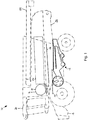
- Combine 10 includes a front elevator housing 14 at the front of the machine for attachment of a header (not shown).
- the header when attached serves to cut and collect the crop material as it progresses across the field, the collected crop stream being conveyed up through the elevator housing 14 into a threshing unit which is represented schematically at 16.
- the threshing unit 16 includes a rotating cylinder 18 and a concave-shaped grate 20.
- the cylinder 18 rotates on a transverse axis and includes rasp bars (not shown) which act upon the crop stream to thresh the grain or seeds from the remaining material, the majority of the threshed grain passing through the underlying grate 20 and onto a grain pan 22.
- the separating apparatus 24 may include a plurality of parallel, longitudinally-aligned, straw walkers (straw-walker combine). Alternatively, the separating apparatus 24 may include one or two longitudinally-aligned rotors which rotate on an longitudinal axis and convey the crop stream rearwardly in a ribbon passing along a spiral path (axial or hybrid combine). In both cases the separating apparatus serve to separate further grain from the crop stream which passes through a grate-like structure onto an underlying return pan 26. The residue crop material, predominantly made up of straw, exits the machine at the rear 28. Although not shown in Figure 1 , a straw spreader and/or chopper may be provided to process the straw material as required.
- the combine 10 includes a driver's cab 30 and an unloading auger 32, shown in the transport position in Figure 1 .
- the threshing and separating apparatus do not remove all MOG from the grain and the crop stream collected by the grain pan 22 and return pan 26 typically includes a proportion of straw, chaff, tailings and other unwanted material such as weed seeds, bugs, and tree twigs.
- a grain cleaning unit is provided to remove this unwanted material thus leaving a clean sample of grain to be delivered to the tank.
- the term 'grain cleaning apparatus' used hereinafter is intended to include the grain pan, the return pan and the cleaning unit comprising the fan unit, chaffer and sieve(s).
- the grain pan 22 and return pan 26 are driven in an oscillating manner as in known machines to convey the grain and MOG accordingly.
- the drive and mounting mechanisms for the grain pan 22 and return pan 26 are not shown, it should be appreciated that this aspect is well known in the art of combine harvesters and is not critical to disclosure of the invention.
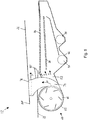
- the two pans 22, 26 may take a ridged construction as is know in the art and also appreciate that Figures 2 - 4 show the grain cleaning apparatus 12 in simplistic form.
- the return pan may be replaced by a non-oscillating conveyor, for example comprising a continuous belt arrangement which catches and conveys the grain and MOG in a forward direction.
- a non-oscillating conveyor for example comprising a continuous belt arrangement which catches and conveys the grain and MOG in a forward direction.
- the oscillating motion of grain pan 22 conveys the combined crop streams rearwardly towards the rear edge 22R of grain pan 22. Whilst conveyed across the grain pan 22 the crop stream, including grain and MOG, undergoes stratification wherein the heavier grain sinks to the bottom layers adjacent grain pan 22 and the lighter/larger MOG rises to the top layers.
- the chaffer 34 is of a known construction and includes a series of transverse slats which create open channels or gaps therebetween.
- the chaffer slats are angled upwardly and rearwardly so as to encourage MOG rearwardly whilst allowing the heavier grain to pass through the chaffer onto an underlying sieve 36.
- the angle of the slats is adjustable to allow changing of the coarseness of the separating action to cater for different conditions and crops.
- Chaffer 34 includes an inclined rear section 34a. MOG which reaches the rear section 34a either passes over the rear edge and out of the machine or through the associated grate before being conveyed to a returns auger 38 for rethreshing in a known manner. It should be appreciated that the majority of materials passing through the rear section 34a is, and is intended to be, unthreshed tailings.
- Grain passing through chaffer 34 is incident on sieve 36 which is also driven in an oscillating manner and serves to remove tailings from the stream of grain before being conveyed to on-board tank (not shown) by grain collecting auger 40 which resides in a transverse trough 42 at the bottom of the cleaning unit 12.
- Tailings 'blocked' by sieve 36 are conveyed rearwardly by the oscillating motion thereof to a rear edge 36R from where the tailings are directed to the returns auger 38 for reprocessing in a known manner.
- the grain cleaning apparatus 12 further comprises a fan unit 64 for generating a first cleaning air stream which is directed through the falling grain/MOG stream as it falls from edge 22R, and through the sieve 36 and chaffer 34.
- the fan unit 64 comprises a fan housing 65 which extends across the width of the combine 10 and beyond the width of grain pan 22.
- the fan housing 65 is cylindrical and is open at both ends to allow air to be drawn in from the environment.
- the fan 66 resides within the fan housing 65 and comprises a transverse fan shaft 68 which supports a plurality of impeller blades 70 and operates on a centrifugal principal.
- Fan shaft 68 is driven in a known manner, typically by a belt and pulley system (not shown) taken its drive from the engine of the combine 10. The drive speed of the fan is adjustable by the operator.
- the fan 66 is shown to include six impeller blades in the drawings although it should be appreciated that more or less impeller blades may be employed.
- the impellor blades 70 draw in air from the transverse ends open to the environment and generate an air stream directed through channel 52 in a generally rearward direction.
- the air stream (designated generally by arrows X) creates a pressure differential across the chaffer 34 and sieve 36 to encourage lighter MOG rearwardly and upwardly whilst allowing the grain to pass through the chaffer 34 and the sieve 36.
- the air stream X also passes above chaffer 34 and below grain pan 22 thus acting upon the crop stream as it falls from the rear edge 22R of the grain pan 22.
- the fan housing 65 includes an opening on its rear side which communicates with the duct 52. It should be understood that duct 52 does not extend across the full width of fan housing 65 and corresponds substantially to the width of the grain pan 22 and chaffer 34.
- the centrally-disposed duct 52 conveys the first cleaning air stream represented by arrows X in Figure 2 , the air stream being directed under the rear edge 22R of grain pan 22 and both above and below the chaffer 34.
- Such a cleaning air stream is common in grain cleaning apparatus of existing combine harvesters.
- the first cleaning air stream propels chaff and lighter MOG rearwardly and out of the rear of the cleaning unit over the rear edge of chaffer 34.
- the invention is concerned with the generation of a second cleaning air stream upstream of the chaffer and sieve assembly.
- the fan housing 65 includes a pair of subsidiary vents 72, one at each end, which each communicate with secondary ducts 74.
- Each secondary duct conveys a respective portion of a second cleaning air stream 'Y' away from the fan housing 65, up and around the sides of grain pan 22 and into respective ends of a transverse air nozzle 76 which is secured to the underside of separator pan 26.
- the transverse air nozzle 76 includes a rearward-directed vent 77 in the form of a slot through which the second cleaning air stream Y is vented above the grain pan 22.
- the passage of second air stream Y is shown diagrammatically by arrows Y in Figure 5 .
- the second air stream serves to engage the lighter and larger MOG which tends to reside in the upper stratified layers of material present on grain pan 22. This lighter crop residue is thereby propelled rearwardly away from the rear edge of grain pan 22 and thus improves the efficiency of the chaffer 34.
- a plurality of fins (or ramps) 85 having a saw-toothed upper edge are provided in a row across the rear of grain pan 22.
- the fins 85 serve to lift the lighter and larger MOG away from the lower layers of grain so as to encourage engagement with the second air stream Y. It should be appreciated however that the fins 85 may be omitted from the construction whilst remaining within the scope of the present invention.
- the secondary ducts 74 may be secured to the respective ends of transverse air nozzle 76 by flexible ducts which permits sufficient movement of the air nozzle 76 as the separator pan oscillates in use.
- flexible ducts or pipes may be formed from rubber or cloth for example and be secured between the secondary ducts 74 and the nozzle 76 by means of jubilee clips for example.
- FIGS 8 to 11 illustrate a second embodiment of the invention in which the second cleaning air stream Y is generated by dedicated additional fans separate from that which generates the first cleaning air stream.
- Like reference numerals will be applied to those features which are common between the two embodiments.
- Grain cleaning apparatus 112 includes a fan unit 130 having a central fan housing 132 and two auxiliary fan housings 133,134 sharing the same axis as central housing 132 but separated therefrom by a respective gap 144.
- Central fan housing 132 houses a main fan 46 having a fan shaft 68 and impeller blades 50 driven thereby.
- Central fan housing 132 includes an opening on its rear side which is communication with a central duct 52 having a similar construction to that described with reference to Figures 2 to 7 above.
- Main fan 46 serves to generate a first cleaning air stream X which is directed under the rear edge 22R of grain pan 22 as above.
- Each auxiliary fan housing 133, 134 houses a respective additional fan 136 (see Figure 8 ) which each include a respective set of impeller blades 138 supported on and driven by fan shaft 68.
- Each auxiliary fan housing 133,134 includes an opening along its rear upper quadrant which is in communication with secondary vents 140,142 which each convey a respective portion of the second cleaning air stream Y to the transverse air nozzle 76.
- the respective portions of second cleaning air stream Y combine inside the transverse air nozzle 76 which is pressurised so as to propel air stream Y through a transverse gap slit.
- Air is drawn in to the central housing 132 and auxiliary housings 133,134 through gaps 144 shown in Figure 11 . Furthermore, the auxiliary fan housings 133,134 are also open at their outside ends through which additional ambient air may be drawn.
- the above described embodiments each generate a first cleaning air stream X and a second air stream Y by means of a fan unit 64,130.
- the respective air streams in both of these examples are not controllable independently.
- the second embodiment described in relation to Figures 8 to 11 may include dedicated fan shafts for each of the additional fans.
- this would permit independent control of the magnitude of the first and second cleaning air streams.
- Figure 12 illustrates a third embodiment of the invention in which the second cleaning air stream Y of grain cleaning apparatus 212 is directed into the volume above the grain pan 22 by a pair of air nozzles 275, 276 which are mounted independently of the separator pan 26.
- the air nozzles 275, 276 are not subject to the vigorous oscillation of the separator pan 26 and, therefore, do not require a flexible connection to the source.
- the nozzles 275, 276 are spaced with sufficient clearance from the separator pan 26 and grain pan 22 so as not to interfere with the operation thereof.
- the nozzles 275, 276 are angled so that the two air streams combine to create a generally linear airflow across the top of the grain pan 22 in a generally rearward direction.
- a combine harvester comprising threshing apparatus, a grain pan and a cleaning unit.
- the grain pan is arranged to collect a grain/chaff stream from the threshing apparatus and is driven in an oscillating manner to convey the collected grain/chaff stream rearwardly to a rear edge from where the grain/chaff stream falls under gravity into the cleaning unit.
- the cleaning unit comprises a fan unit for generating a first cleaning airstream which is directed under the grain pan and through the grain/chaff stream falling from said rear edge.
- the combine harvester further comprises means to generate a second cleaning airstream directed over the grain pan.
Landscapes
- Life Sciences & Earth Sciences (AREA)
- Environmental Sciences (AREA)
- Threshing Machine Elements (AREA)
- Combines (AREA)
Claims (13)
- Moissonneuse-batteuse (10) comprenant un dispositif de battage (16), un plateau à grain (22) et une unité de nettoyage, le plateau à grain étant agencé de manière à collecter un flux de grains/paillettes (A, B) tombant par gravité du dispositif de battage et étant entraîné d'une manière oscillante afin de transporter le flux de grains/paillettes collecté vers l'arrière, vers un bord arrière (22R) à partir duquel le flux de grains/paillettes tombe par gravité dans l'unité de nettoyage (12), l'unité de nettoyage comprenant une unité formant ventilateur (64) avec un boîtier de ventilateur (65) afin de produire un premier courant d'air de nettoyage (X) qui est dirigé au-dessous du plateau à grain et transversalement au flux de grains/paillettes tombant à partir dudit bord arrière,
caractérisée en ce que la moissonneuse-batteuse comprend, en outre :
une paire de conduits secondaires (74) pouvant laisser passer de l'air à partir d'une paire d'évents secondaires (72) dans le boîtier de ventilateur (65) vers le haut et sur les côtés du plateau à grain (22), et vers des extrémités respectives d'un injecteur d'air transversal (76) fixé sur la face inférieure d'un plateau de séparation (26) et comportant au moins un évent (77), sous forme d'une fente, dirigé vers l'arrière, ledit passage étant situé au-dessus du grain, et séparé de ce dernier, afin de diriger un second courant d'air de nettoyage (Y) au-dessus du flux de grains/paillettes disposé sur le plateau à grain et en aval du flux de grains/paillettes (A, B) tombant du dispositif de battage. - Moissonneuse-batteuse selon la revendication 1, dans laquelle ladite unité formant ventilateur produit ledit second courant d'air de nettoyage.
- Moissonneuse-batteuse selon la revendication 2, dans laquelle l'unité formant ventilateur comprend une pluralité de lames de rotor montées sur un arbre de ventilateur orienté transversalement et tourne à l'intérieur d'un boîtier de ventilateur situé sous le plateau à grain, et dans laquelle un premier conduit transporte le premier courant d'air de nettoyage à partir d'une partie centrale du boîtier de ventilateur sous le bord arrière du plateau à grain.
- Moissonneuse-batteuse selon la revendication 3, dans laquelle les lames de rotor et le boîtier de ventilateur s'étendent au delà de la largeur du plateau à grain, et au moins un autre conduit transporte le second courant d'air de nettoyage à partir d'une zone d'extrémité du boîtier de ventilateur autour du plateau à grain.
- Moissonneuse-batteuse selon la revendication 3, dans laquelle les lames de rotor et le boîtier de ventilateur sont contenus à l'intérieur de la largeur du plateau à grain afin de former un ventilateur principal et l'unité formant ventilateur comprend au moins un ventilateur additionnel qui produit ledit second courant d'air de nettoyage,
- Moissonneuse-batteuse selon la revendication 5, dans laquelle le au moins un ventilateur additionnel comprend des lames de rotor contenues à l'extérieur de la largeur du plateau à grain.
- Moissonneuse-batteuse selon la revendication 6, dans laquelle les lames de rotor du ventilateur principal et le au moins un ventilateur additionnel partagent un arbre de ventilateur commun.
- Moissonneuse-batteuse selon l'une quelconque des revendications 2 à 7, dans laquelle l'unité formant ventilateur produit ledit second courant d'air de nettoyage en deux parties à partir de ses deux extrémités, et dans laquelle les deux parties sont transférées par l'intermédiaire de conduits respectifs autour des côtés du plateau à grain.
- Moissonneuse-batteuse selon l'une quelconque des revendications précédentes, dans laquelle le dispositif de battage comprend une unité de battage agencée afin de recevoir et de battre un flux de récolte, la moissonneuse-batteuse comprenant, en outre, un dispositif de séparation positionné en aval et vers l'arrière de l'unité de battage et agencé afin de recevoir le flux de récolte battu et de le transporter vers l'arrière, à la fois l'unité de battage et le dispositif de séparation comprenant des grilles respectives afin de permettre la chute par gravité des grains et paillettes respectivement sur le plateau à grain et un convoyeur de retour, le convoyeur de retour étant destiné à transférer un flux secondaire de grains/paillettes vers l'avant, vers un bord avant à partir duquel le flux secondaire de grains/paillettes tombe par gravité afin de se mélanger avec le flux de grains/paillettes sur le plateau à grain, et dans laquelle le convoyeur de retour forme un plafond sur un passage à travers lequel passe le second courant d'air de nettoyage.
- Moissonneuse-batteuse selon la revendication 9, dans laquelle le second courant d'air de nettoyage est évacué dans une zone au-dessus du plateau à grain par un ou plusieurs évents fixés sur la face inférieure du convoyeur de retour.
- Moissonneuse-batteuse selon l'une quelconque des revendications précédentes, dans laquelle une pluralité d'ailettes verticales est fixée sur le plateau à grain de manière adjacente au bord arrière afin de soulever du matériau plus léger dans le flux de grains/paillettes en l'écartant du matériau plus lourd et d'améliorer la stratification de celui-ci.
- Moissonneuse-batteuse selon la revendication 11, dans laquelle chaque ailette comporte un bord supérieur en dent de scie.
- Moissonneuse-batteuse selon la revendication 11 ou 12, dans laquelle les ailettes de ladite pluralité d'ailettes sont espacées les unes des autres suivant une rangée sur la largeur du plateau à grain.
Applications Claiming Priority (2)
| Application Number | Priority Date | Filing Date | Title |
|---|---|---|---|
| GBGB1221347.6A GB201221347D0 (en) | 2012-11-28 | 2012-11-28 | Crop processing apparatus in a combine harvester |
| PCT/EP2013/074124 WO2014082890A1 (fr) | 2012-11-28 | 2013-11-19 | Appareil de traitement de culture dans une moissonneuse-batteuse |
Publications (2)
| Publication Number | Publication Date |
|---|---|
| EP2925116A1 EP2925116A1 (fr) | 2015-10-07 |
| EP2925116B1 true EP2925116B1 (fr) | 2020-02-26 |
Family
ID=47560764
Family Applications (1)
| Application Number | Title | Priority Date | Filing Date |
|---|---|---|---|
| EP13792033.6A Active EP2925116B1 (fr) | 2012-11-28 | 2013-11-19 | Appareil de traitement de récolte dans une moissonneuse-batteuse |
Country Status (5)
| Country | Link |
|---|---|
| US (1) | US9717183B2 (fr) |
| EP (1) | EP2925116B1 (fr) |
| BR (1) | BR112015011936B1 (fr) |
| GB (1) | GB201221347D0 (fr) |
| WO (1) | WO2014082890A1 (fr) |
Families Citing this family (9)
| Publication number | Priority date | Publication date | Assignee | Title |
|---|---|---|---|---|
| WO2016096839A1 (fr) * | 2014-12-17 | 2016-06-23 | Agco International Gmbh | Appareil de traitement de récolte dans une moissonneuse-batteuse |
| GB201515948D0 (en) | 2015-09-09 | 2015-10-21 | Agco Int Gmbh | Grain cleaning system in a combine harvester |
| DE102016104027A1 (de) | 2016-03-07 | 2017-09-07 | Claas Selbstfahrende Erntemaschinen Gmbh | Mähdrescher |
| US10219439B1 (en) | 2017-08-14 | 2019-03-05 | Cnh Industrial America Llc | Harvester cleaning system with conveyor enhanced cascades |
| CN107926291A (zh) | 2017-11-20 | 2018-04-20 | 江苏大学 | 一种贯流热风式联合收割机潮湿物料输送喂入装置 |
| CN108855400A (zh) * | 2018-06-15 | 2018-11-23 | 韩立宏 | 新式碎石机 |
| WO2021001681A1 (fr) * | 2019-07-03 | 2021-01-07 | Harjeet Singh | Batteuse à tambour inférieur |
| GB202017131D0 (en) * | 2020-10-29 | 2020-12-16 | Agco Int Gmbh | Cleaning systems for combine harvesters having airbags or other movable side members, and related methods |
| CN114311399B (zh) * | 2022-02-15 | 2023-12-15 | 贵州华晟恒信电力通讯科技有限公司 | 一种塑料管生产用原料高效粉碎装置 |
Family Cites Families (40)
| Publication number | Priority date | Publication date | Assignee | Title |
|---|---|---|---|---|
| US2937647A (en) | 1958-06-09 | 1960-05-24 | Allis Chalmers Mfg Co | Grain separating mechanism for combine |
| US3603063A (en) * | 1969-12-10 | 1971-09-07 | Clark E Stroburg | Combine |
| US3833006A (en) * | 1972-12-01 | 1974-09-03 | Allis Chalmers | Duct damper for transverse fan |
| US3800804A (en) * | 1973-02-05 | 1974-04-02 | Allis Chalmers | Double outlet transverse fan |
| US4007744A (en) * | 1975-07-02 | 1977-02-15 | Allis-Chalmers Corporation | Grain accelerator precleaner |
| GB2063034B (en) * | 1979-11-14 | 1983-05-18 | Sperry Nv | Combine harvesters |
| US4353376A (en) * | 1981-03-12 | 1982-10-12 | Schuler Murry W | Combine having separating and cleaning apparatus |
| DE3173652D1 (en) | 1981-10-21 | 1986-03-13 | Deere & Co | Grain pan for harvesters |
| DE3228326A1 (de) * | 1982-07-29 | 1984-02-09 | Claas Ohg, 4834 Harsewinkel | Selbstfahrender maehdrescher |
| US4465082A (en) * | 1982-08-17 | 1984-08-14 | Sperry Corporation | Impeller for rotary cleaning mechanism in combines |
| IT1159987B (it) | 1983-11-30 | 1987-03-04 | Laverda Spa Pietro | Perfezionamenti alle macchine mieti trebbiatrici |
| US4589425A (en) * | 1984-07-02 | 1986-05-20 | Mitchell Jr Thomas A | Control apparatus for a combine |
| US4627446A (en) * | 1985-03-14 | 1986-12-09 | Deutz-Allis Corporation | Downwardly and rearwardly directed air stream for harvester with vertically offset accelerator rolls |
| US5098341A (en) * | 1990-11-26 | 1992-03-24 | Kuchar George J | Air diverter for chaff removal in a combine |
| DE4138530A1 (de) * | 1991-11-23 | 1993-05-27 | Kloeckner Humboldt Deutz Ag | Reinigungsvorrichtung fuer maehdrescher |
| US5387154A (en) | 1993-05-10 | 1995-02-07 | Deere & Company | Two outlet cleaning fan |
| CA2146842A1 (fr) | 1994-05-26 | 1995-11-27 | Fritz Karl Lauer | Enveloppe de ventilateur de nettoyage a coupure d'air non uniforme |
| AT401596B (de) * | 1994-05-27 | 1996-10-25 | Wintersteiger Gmbh & Co | Siebvorrichtung für einen mähdrescher, insbesondere für einen versuchsfeldmähdrescher |
| GB2293080A (en) * | 1994-09-17 | 1996-03-20 | New Holland Belguim Nv | Grain cleaner for combine harvester |
| CA2142218C (fr) * | 1995-02-10 | 1999-06-15 | Philip E. Meyers | Deflecteur d'ecoulement d'air pour moissonneuse-batteuse |
| JP3362309B2 (ja) | 1995-11-20 | 2003-01-07 | ヤンマー農機株式会社 | コンバインの脱穀装置 |
| GB2365312A (en) * | 2000-08-01 | 2002-02-20 | Claas Selbstfahr Erntemasch | Grain cleaning apparatus for combines |
| DE10064356A1 (de) * | 2000-12-21 | 2002-07-11 | Claas Selbstfahr Erntemasch | Vorrichtung und Verfahren zur Erntegutförderung in landwirtschaftlichen Arbeitsmaschinen |
| US6773343B2 (en) * | 2002-07-31 | 2004-08-10 | Deere & Company | Front chaffer and cleaning fan |
| DE10307705A1 (de) * | 2003-02-21 | 2004-09-16 | Claas Selbstfahrende Erntemaschinen Gmbh | Verfahren und Vorrichtung zum Trennen eines Erntegutstroms |
| DE10360597A1 (de) * | 2003-12-19 | 2005-07-28 | Claas Selbstfahrende Erntemaschinen Gmbh | Verfahren und Vorrichtung zur Regelung von Arbeitsorganen eines Mähdreschers |
| DE102005016950A1 (de) * | 2005-04-12 | 2006-10-19 | Claas Selbstfahrende Erntemaschinen Gmbh | Antriebssystem für eine Erntegutfördereinrichtung |
| DE102005026608A1 (de) | 2005-06-09 | 2007-01-04 | Deere & Company, Moline | Reinigungseinrichtung für einen Mähdrescher |
| DE102005027741A1 (de) * | 2005-06-16 | 2007-01-18 | Deere & Company, Moline | Sieb für eine Reinigungseinrichtung eines Mähdreschers |
| US7670219B2 (en) * | 2006-12-13 | 2010-03-02 | Cnh America Llc | Integrated axle and cleaning fan wrapper for an agricultural harvesting machine |
| GB2452241A (en) | 2007-06-08 | 2009-03-04 | Agco Do Brasil Com E Ind Stria | Combine harvester fan |
| GB2487193A (en) * | 2011-01-11 | 2012-07-18 | Agco As | Combine harvester grain cleaning apparatus |
| GB2487196A (en) * | 2011-01-11 | 2012-07-18 | Agco As | Combine harvester grain cleaning apparatus |
| GB201100675D0 (en) | 2011-01-17 | 2011-03-02 | Agco As | Combine harvester grain cleaning apparatus |
| US9814184B2 (en) * | 2011-11-09 | 2017-11-14 | Cnh Industrial America Llc | Crop material flow control system |
| US8608534B1 (en) * | 2012-09-25 | 2013-12-17 | Agco Corporation | Rolled secondary cut off in air distribution system of a combine harvester |
| US9033779B2 (en) * | 2012-11-29 | 2015-05-19 | Cnh Industrial America Llc | Air diverter for a cleaning system of a combine harvester |
| US8821229B2 (en) * | 2012-12-06 | 2014-09-02 | Cnh Industrial America Llc | Grain cleaning system for an agricultural combine |
| US9345197B2 (en) * | 2013-05-10 | 2016-05-24 | Agco Corporation | Combine harvester with even crop distribution |
| US9295197B1 (en) * | 2014-10-14 | 2016-03-29 | Cnh Industrial America Llc | Combine harvester with blower equipped elevator |
-
2012
- 2012-11-28 GB GBGB1221347.6A patent/GB201221347D0/en not_active Ceased
-
2013
- 2013-11-19 WO PCT/EP2013/074124 patent/WO2014082890A1/fr not_active Ceased
- 2013-11-19 US US14/442,478 patent/US9717183B2/en not_active Expired - Fee Related
- 2013-11-19 BR BR112015011936-0A patent/BR112015011936B1/pt not_active IP Right Cessation
- 2013-11-19 EP EP13792033.6A patent/EP2925116B1/fr active Active
Non-Patent Citations (1)
| Title |
|---|
| None * |
Also Published As
| Publication number | Publication date |
|---|---|
| WO2014082890A1 (fr) | 2014-06-05 |
| US9717183B2 (en) | 2017-08-01 |
| US20160270295A1 (en) | 2016-09-22 |
| EP2925116A1 (fr) | 2015-10-07 |
| GB201221347D0 (en) | 2013-01-09 |
| BR112015011936B1 (pt) | 2020-10-20 |
| BR112015011936A2 (pt) | 2017-07-11 |
Similar Documents
| Publication | Publication Date | Title |
|---|---|---|
| EP2925116B1 (fr) | Appareil de traitement de récolte dans une moissonneuse-batteuse | |
| US9426943B2 (en) | Combine harvester grain cleaning apparatus | |
| US20140080554A1 (en) | Combine Harvester Grain Cleaning Apparatus | |
| US10321634B2 (en) | Combine harvester grain cleaning system | |
| US10405493B2 (en) | Fan in beater to avoid strawhood blockages | |
| US8608534B1 (en) | Rolled secondary cut off in air distribution system of a combine harvester | |
| US9867336B2 (en) | Combine harvester grain cleaning system | |
| US11291160B2 (en) | Agricultural harvester and a dust extractor for the agricultural harvester | |
| US20090163260A1 (en) | Combine harvester having blower for pneumatic cleaning | |
| US9883631B2 (en) | Crop processing apparatus in a combine harvester | |
| US5088960A (en) | Air blast for cleaning axial separator | |
| WO2021144701A1 (fr) | Système de nettoyage de grains de moissonneuse-batteuse | |
| EP4159026A1 (fr) | Unité de battage pour une moissonneuse-batteuse et moissonneuse-batteuse utilisant une telle unité | |
| US10091940B2 (en) | Straw walker arrangement for an agricultural harvester | |
| US20250081887A1 (en) | Chaff Spreader for a Combine Harvester | |
| US20250331464A1 (en) | Aspiration system for agricultural vehicle | |
| US20250048973A1 (en) | Straw Chopper for a Combine Harvester | |
| EP3481172B1 (fr) | Moissoneuse batteuse avec un dispositif de traitement de récolte |
Legal Events
| Date | Code | Title | Description |
|---|---|---|---|
| PUAI | Public reference made under article 153(3) epc to a published international application that has entered the european phase |
Free format text: ORIGINAL CODE: 0009012 |
|
| 17P | Request for examination filed |
Effective date: 20150629 |
|
| AK | Designated contracting states |
Kind code of ref document: A1 Designated state(s): AL AT BE BG CH CY CZ DE DK EE ES FI FR GB GR HR HU IE IS IT LI LT LU LV MC MK MT NL NO PL PT RO RS SE SI SK SM TR |
|
| AX | Request for extension of the european patent |
Extension state: BA ME |
|
| RIN1 | Information on inventor provided before grant (corrected) |
Inventor name: BILDE, MORTEN LETH |
|
| DAX | Request for extension of the european patent (deleted) | ||
| STAA | Information on the status of an ep patent application or granted ep patent |
Free format text: STATUS: EXAMINATION IS IN PROGRESS |
|
| 17Q | First examination report despatched |
Effective date: 20181127 |
|
| GRAP | Despatch of communication of intention to grant a patent |
Free format text: ORIGINAL CODE: EPIDOSNIGR1 |
|
| STAA | Information on the status of an ep patent application or granted ep patent |
Free format text: STATUS: GRANT OF PATENT IS INTENDED |
|
| INTG | Intention to grant announced |
Effective date: 20191021 |
|
| GRAS | Grant fee paid |
Free format text: ORIGINAL CODE: EPIDOSNIGR3 |
|
| GRAA | (expected) grant |
Free format text: ORIGINAL CODE: 0009210 |
|
| STAA | Information on the status of an ep patent application or granted ep patent |
Free format text: STATUS: THE PATENT HAS BEEN GRANTED |
|
| AK | Designated contracting states |
Kind code of ref document: B1 Designated state(s): AL AT BE BG CH CY CZ DE DK EE ES FI FR GB GR HR HU IE IS IT LI LT LU LV MC MK MT NL NO PL PT RO RS SE SI SK SM TR |
|
| REG | Reference to a national code |
Ref country code: GB Ref legal event code: FG4D |
|
| REG | Reference to a national code |
Ref country code: CH Ref legal event code: EP |
|
| REG | Reference to a national code |
Ref country code: DE Ref legal event code: R096 Ref document number: 602013066277 Country of ref document: DE |
|
| REG | Reference to a national code |
Ref country code: AT Ref legal event code: REF Ref document number: 1236514 Country of ref document: AT Kind code of ref document: T Effective date: 20200315 |
|
| REG | Reference to a national code |
Ref country code: IE Ref legal event code: FG4D |
|
| PG25 | Lapsed in a contracting state [announced via postgrant information from national office to epo] |
Ref country code: RS Free format text: LAPSE BECAUSE OF FAILURE TO SUBMIT A TRANSLATION OF THE DESCRIPTION OR TO PAY THE FEE WITHIN THE PRESCRIBED TIME-LIMIT Effective date: 20200226 Ref country code: FI Free format text: LAPSE BECAUSE OF FAILURE TO SUBMIT A TRANSLATION OF THE DESCRIPTION OR TO PAY THE FEE WITHIN THE PRESCRIBED TIME-LIMIT Effective date: 20200226 Ref country code: NO Free format text: LAPSE BECAUSE OF FAILURE TO SUBMIT A TRANSLATION OF THE DESCRIPTION OR TO PAY THE FEE WITHIN THE PRESCRIBED TIME-LIMIT Effective date: 20200526 |
|
| REG | Reference to a national code |
Ref country code: NL Ref legal event code: MP Effective date: 20200226 |
|
| REG | Reference to a national code |
Ref country code: LT Ref legal event code: MG4D |
|
| PG25 | Lapsed in a contracting state [announced via postgrant information from national office to epo] |
Ref country code: HR Free format text: LAPSE BECAUSE OF FAILURE TO SUBMIT A TRANSLATION OF THE DESCRIPTION OR TO PAY THE FEE WITHIN THE PRESCRIBED TIME-LIMIT Effective date: 20200226 Ref country code: BG Free format text: LAPSE BECAUSE OF FAILURE TO SUBMIT A TRANSLATION OF THE DESCRIPTION OR TO PAY THE FEE WITHIN THE PRESCRIBED TIME-LIMIT Effective date: 20200526 Ref country code: GR Free format text: LAPSE BECAUSE OF FAILURE TO SUBMIT A TRANSLATION OF THE DESCRIPTION OR TO PAY THE FEE WITHIN THE PRESCRIBED TIME-LIMIT Effective date: 20200527 Ref country code: SE Free format text: LAPSE BECAUSE OF FAILURE TO SUBMIT A TRANSLATION OF THE DESCRIPTION OR TO PAY THE FEE WITHIN THE PRESCRIBED TIME-LIMIT Effective date: 20200226 Ref country code: LV Free format text: LAPSE BECAUSE OF FAILURE TO SUBMIT A TRANSLATION OF THE DESCRIPTION OR TO PAY THE FEE WITHIN THE PRESCRIBED TIME-LIMIT Effective date: 20200226 Ref country code: IS Free format text: LAPSE BECAUSE OF FAILURE TO SUBMIT A TRANSLATION OF THE DESCRIPTION OR TO PAY THE FEE WITHIN THE PRESCRIBED TIME-LIMIT Effective date: 20200626 |
|
| PG25 | Lapsed in a contracting state [announced via postgrant information from national office to epo] |
Ref country code: NL Free format text: LAPSE BECAUSE OF FAILURE TO SUBMIT A TRANSLATION OF THE DESCRIPTION OR TO PAY THE FEE WITHIN THE PRESCRIBED TIME-LIMIT Effective date: 20200226 |
|
| PG25 | Lapsed in a contracting state [announced via postgrant information from national office to epo] |
Ref country code: SK Free format text: LAPSE BECAUSE OF FAILURE TO SUBMIT A TRANSLATION OF THE DESCRIPTION OR TO PAY THE FEE WITHIN THE PRESCRIBED TIME-LIMIT Effective date: 20200226 Ref country code: RO Free format text: LAPSE BECAUSE OF FAILURE TO SUBMIT A TRANSLATION OF THE DESCRIPTION OR TO PAY THE FEE WITHIN THE PRESCRIBED TIME-LIMIT Effective date: 20200226 Ref country code: CZ Free format text: LAPSE BECAUSE OF FAILURE TO SUBMIT A TRANSLATION OF THE DESCRIPTION OR TO PAY THE FEE WITHIN THE PRESCRIBED TIME-LIMIT Effective date: 20200226 Ref country code: EE Free format text: LAPSE BECAUSE OF FAILURE TO SUBMIT A TRANSLATION OF THE DESCRIPTION OR TO PAY THE FEE WITHIN THE PRESCRIBED TIME-LIMIT Effective date: 20200226 Ref country code: SM Free format text: LAPSE BECAUSE OF FAILURE TO SUBMIT A TRANSLATION OF THE DESCRIPTION OR TO PAY THE FEE WITHIN THE PRESCRIBED TIME-LIMIT Effective date: 20200226 Ref country code: DK Free format text: LAPSE BECAUSE OF FAILURE TO SUBMIT A TRANSLATION OF THE DESCRIPTION OR TO PAY THE FEE WITHIN THE PRESCRIBED TIME-LIMIT Effective date: 20200226 Ref country code: PT Free format text: LAPSE BECAUSE OF FAILURE TO SUBMIT A TRANSLATION OF THE DESCRIPTION OR TO PAY THE FEE WITHIN THE PRESCRIBED TIME-LIMIT Effective date: 20200719 Ref country code: LT Free format text: LAPSE BECAUSE OF FAILURE TO SUBMIT A TRANSLATION OF THE DESCRIPTION OR TO PAY THE FEE WITHIN THE PRESCRIBED TIME-LIMIT Effective date: 20200226 Ref country code: ES Free format text: LAPSE BECAUSE OF FAILURE TO SUBMIT A TRANSLATION OF THE DESCRIPTION OR TO PAY THE FEE WITHIN THE PRESCRIBED TIME-LIMIT Effective date: 20200226 |
|
| REG | Reference to a national code |
Ref country code: AT Ref legal event code: MK05 Ref document number: 1236514 Country of ref document: AT Kind code of ref document: T Effective date: 20200226 |
|
| REG | Reference to a national code |
Ref country code: DE Ref legal event code: R097 Ref document number: 602013066277 Country of ref document: DE |
|
| PLBE | No opposition filed within time limit |
Free format text: ORIGINAL CODE: 0009261 |
|
| STAA | Information on the status of an ep patent application or granted ep patent |
Free format text: STATUS: NO OPPOSITION FILED WITHIN TIME LIMIT |
|
| PG25 | Lapsed in a contracting state [announced via postgrant information from national office to epo] |
Ref country code: AT Free format text: LAPSE BECAUSE OF FAILURE TO SUBMIT A TRANSLATION OF THE DESCRIPTION OR TO PAY THE FEE WITHIN THE PRESCRIBED TIME-LIMIT Effective date: 20200226 Ref country code: IT Free format text: LAPSE BECAUSE OF FAILURE TO SUBMIT A TRANSLATION OF THE DESCRIPTION OR TO PAY THE FEE WITHIN THE PRESCRIBED TIME-LIMIT Effective date: 20200226 |
|
| PGFP | Annual fee paid to national office [announced via postgrant information from national office to epo] |
Ref country code: DE Payment date: 20201119 Year of fee payment: 8 Ref country code: FR Payment date: 20201120 Year of fee payment: 8 |
|
| 26N | No opposition filed |
Effective date: 20201127 |
|
| PG25 | Lapsed in a contracting state [announced via postgrant information from national office to epo] |
Ref country code: PL Free format text: LAPSE BECAUSE OF FAILURE TO SUBMIT A TRANSLATION OF THE DESCRIPTION OR TO PAY THE FEE WITHIN THE PRESCRIBED TIME-LIMIT Effective date: 20200226 Ref country code: SI Free format text: LAPSE BECAUSE OF FAILURE TO SUBMIT A TRANSLATION OF THE DESCRIPTION OR TO PAY THE FEE WITHIN THE PRESCRIBED TIME-LIMIT Effective date: 20200226 |
|
| PG25 | Lapsed in a contracting state [announced via postgrant information from national office to epo] |
Ref country code: MC Free format text: LAPSE BECAUSE OF FAILURE TO SUBMIT A TRANSLATION OF THE DESCRIPTION OR TO PAY THE FEE WITHIN THE PRESCRIBED TIME-LIMIT Effective date: 20200226 |
|
| REG | Reference to a national code |
Ref country code: CH Ref legal event code: PL |
|
| GBPC | Gb: european patent ceased through non-payment of renewal fee |
Effective date: 20201119 |
|
| PG25 | Lapsed in a contracting state [announced via postgrant information from national office to epo] |
Ref country code: LU Free format text: LAPSE BECAUSE OF NON-PAYMENT OF DUE FEES Effective date: 20201119 |
|
| REG | Reference to a national code |
Ref country code: BE Ref legal event code: MM Effective date: 20201130 |
|
| PG25 | Lapsed in a contracting state [announced via postgrant information from national office to epo] |
Ref country code: LI Free format text: LAPSE BECAUSE OF NON-PAYMENT OF DUE FEES Effective date: 20201130 Ref country code: CH Free format text: LAPSE BECAUSE OF NON-PAYMENT OF DUE FEES Effective date: 20201130 |
|
| PG25 | Lapsed in a contracting state [announced via postgrant information from national office to epo] |
Ref country code: IE Free format text: LAPSE BECAUSE OF NON-PAYMENT OF DUE FEES Effective date: 20201119 |
|
| PG25 | Lapsed in a contracting state [announced via postgrant information from national office to epo] |
Ref country code: GB Free format text: LAPSE BECAUSE OF NON-PAYMENT OF DUE FEES Effective date: 20201119 |
|
| PG25 | Lapsed in a contracting state [announced via postgrant information from national office to epo] |
Ref country code: TR Free format text: LAPSE BECAUSE OF FAILURE TO SUBMIT A TRANSLATION OF THE DESCRIPTION OR TO PAY THE FEE WITHIN THE PRESCRIBED TIME-LIMIT Effective date: 20200226 Ref country code: MT Free format text: LAPSE BECAUSE OF FAILURE TO SUBMIT A TRANSLATION OF THE DESCRIPTION OR TO PAY THE FEE WITHIN THE PRESCRIBED TIME-LIMIT Effective date: 20200226 Ref country code: CY Free format text: LAPSE BECAUSE OF FAILURE TO SUBMIT A TRANSLATION OF THE DESCRIPTION OR TO PAY THE FEE WITHIN THE PRESCRIBED TIME-LIMIT Effective date: 20200226 |
|
| REG | Reference to a national code |
Ref country code: DE Ref legal event code: R119 Ref document number: 602013066277 Country of ref document: DE |
|
| PG25 | Lapsed in a contracting state [announced via postgrant information from national office to epo] |
Ref country code: MK Free format text: LAPSE BECAUSE OF FAILURE TO SUBMIT A TRANSLATION OF THE DESCRIPTION OR TO PAY THE FEE WITHIN THE PRESCRIBED TIME-LIMIT Effective date: 20200226 Ref country code: AL Free format text: LAPSE BECAUSE OF FAILURE TO SUBMIT A TRANSLATION OF THE DESCRIPTION OR TO PAY THE FEE WITHIN THE PRESCRIBED TIME-LIMIT Effective date: 20200226 |
|
| PG25 | Lapsed in a contracting state [announced via postgrant information from national office to epo] |
Ref country code: BE Free format text: LAPSE BECAUSE OF NON-PAYMENT OF DUE FEES Effective date: 20201130 |
|
| PG25 | Lapsed in a contracting state [announced via postgrant information from national office to epo] |
Ref country code: DE Free format text: LAPSE BECAUSE OF NON-PAYMENT OF DUE FEES Effective date: 20220601 |
|
| PG25 | Lapsed in a contracting state [announced via postgrant information from national office to epo] |
Ref country code: FR Free format text: LAPSE BECAUSE OF NON-PAYMENT OF DUE FEES Effective date: 20211130 |
|
| PG25 | Lapsed in a contracting state [announced via postgrant information from national office to epo] |
Ref country code: IS Free format text: LAPSE BECAUSE OF NON-PAYMENT OF DUE FEES Effective date: 20200626 |