EP2926203B1 - Appareil de terrain permettant de déterminer ou de surveiller une grandeur de processus en technique d'automatisation - Google Patents
Appareil de terrain permettant de déterminer ou de surveiller une grandeur de processus en technique d'automatisation Download PDFInfo
- Publication number
- EP2926203B1 EP2926203B1 EP13783587.2A EP13783587A EP2926203B1 EP 2926203 B1 EP2926203 B1 EP 2926203B1 EP 13783587 A EP13783587 A EP 13783587A EP 2926203 B1 EP2926203 B1 EP 2926203B1
- Authority
- EP
- European Patent Office
- Prior art keywords
- channel
- current
- channels
- field device
- voter
- Prior art date
- Legal status (The legal status is an assumption and is not a legal conclusion. Google has not performed a legal analysis and makes no representation as to the accuracy of the status listed.)
- Active
Links
Images




Classifications
-
- G—PHYSICS
- G05—CONTROLLING; REGULATING
- G05B—CONTROL OR REGULATING SYSTEMS IN GENERAL; FUNCTIONAL ELEMENTS OF SUCH SYSTEMS; MONITORING OR TESTING ARRANGEMENTS FOR SUCH SYSTEMS OR ELEMENTS
- G05B9/00—Safety arrangements
- G05B9/02—Safety arrangements electric
- G05B9/03—Safety arrangements electric with multiple-channel loop, i.e. redundant control systems
-
- G—PHYSICS
- G05—CONTROLLING; REGULATING
- G05B—CONTROL OR REGULATING SYSTEMS IN GENERAL; FUNCTIONAL ELEMENTS OF SUCH SYSTEMS; MONITORING OR TESTING ARRANGEMENTS FOR SUCH SYSTEMS OR ELEMENTS
- G05B9/00—Safety arrangements
- G05B9/02—Safety arrangements electric
Definitions
- the invention relates to a field device for determining or monitoring a process variable in automation technology.
- the field device is designed so that it meets a safety standard that is required in a given safety-critical application.
- the field device comprises a sensor, which operates according to a defined measurement principle, and a control / evaluation unit, which processes and evaluates the measurement data supplied by the sensor along at least three redundant and / or diversely designed measurement channels.
- a suitable solution is from the WO 2004/013585 A1 known.
- field devices are used which are used to determine and monitor process variables.
- field devices are level gauges, flowmeters, analyzers, pressure and temperature measuring devices, humidity and conductivity meters, density and viscosity meters.
- the sensors of these field devices detect the corresponding process variables, e.g. level, flow, pH, substance concentration, pressure, temperature, humidity, conductivity, density or viscosity.
- field devices in modern automation systems are connected via communication networks, such as HART multidrop, point-to-point connection, Profibus, Foundation Fieldbus, to a superordinated unit, which is referred to as a control system or control room.
- This higher-level unit is used for process control, process visualization, process monitoring and commissioning and for operating the field devices.
- Additional components necessary for the operation of fieldbus systems which are directly connected to a fieldbus and which in particular serve for communication with the higher-level units, are also frequently referred to as field devices. These additional components are, for. For example, remote I / Os, gateways, linking devices, controllers or wireless adapters.
- the field devices must meet a wide variety of security requirements.
- the field devices In order to meet the respective security requirements, e.g. IEC61508 (SIL standard 'Safety Integrity Level'), the field devices must be redundant and / or diversified.
- Redundancy means increased safety through double or multiple design of all safety-related hardware and software components.
- Diversity means that the hardware components located in the different measurement channels, e.g. a microprocessor, from different manufacturers and / or that they are of different types.
- software components diversity requires that the software stored in the microprocessors come from different sources, ie from different manufacturers or programmers. All these measures are intended to ensure that a safety-critical failure of the field device as well as the occurrence of simultaneously occurring systematic errors in the provision of the measured value is excluded with a high degree of probability.
- An example of a safety-relevant application is the level monitoring in a tank in which a flammable or a non-flammable, but water-polluting liquid is stored.
- a flammable or a non-flammable, but water-polluting liquid is stored.
- it must be ensured that the supply of liquid to the tank is interrupted immediately as soon as a maximum permissible level is reached. This, in turn, requires that the meter reliably detects the level and operates without errors.
- the measuring channel is designed to be redundant and / or diverse, however, the voter, usually a microprocessor, represents the Achilles heel of a field device which should meet high and highest safety requirements.
- the microprocessor is designed monolithic. If a dangerous fault occurs (according to the nomenclature of the aforementioned standard), the field device fails. In order to meet the requirements of SIL 3, the proportion of dangerous faults to the number of all possible faults may not exceed one per cent. With a conventional microprocessor, this level of security can not be achieved.
- the publication DE102009026785 A1 relates to a field device for determining and / or monitoring a physical or chemical process variable, consisting of a sensor which operates in accordance with a predetermined measurement principle, and a control evaluation unit, the measured data / measured values supplied by the sensor depending on one in the respective safety critical Application requested safety standard along a predetermined number of redundant or diversified or redundant and diversified measuring paths processed and / or evaluated.
- the invention has for its object to provide a field device, which is characterized by increased functional safety.
- the object is achieved by a field device for determining or monitoring a process variable in automation technology according to claim 1.
- each Stromeinstellkanal a Stromeinstelliser and a current control wherein the Stromeinstelliser and the current control are connected in parallel.
- the voter consists of several components that are at least partially or completely designed twice redundant.
- the voter be a majority voter having a plurality of voter channels, wherein the following components are found in each voter channel: a comparator stage through which the output signals provided by the individual current setting channels are compared with each other, an error detection stage provided by appropriately linking the voters Output signals of the comparator stages associated with the voter channels detects a malfunction occurring in a measurement channel or in a current setting channel, and a turn-off stage which turns off the current setting channel in which the error detection stage detects a malfunction.
- each Voterkanal comprises part of the comparator stage, part of the error detection unit and part of the Ausschaltcut, and that each Voterkanal is designed as an integrated part of the associated measurement channel and the associated Stromeinstellkanals.
- the comparator stage for each Voterkanal comprises two comparator modules, which compares the output signals of the associated Stromeinstellkanals with the output signals of the remaining Stromeinstellkanäle.
- each of the error detection stages is a logic stage constructed of two NAND gates, the output signals of the comparators of a first Voter channel being associated with a selected measurement channel at the inputs of the first NAND gate, and at the second NAND Gate applied to the inputs of the first NAND gate redundant outputs of the comparators of the second Voterkanals and the third Voterkanals, and wherein the outputs of the first NAND gate and the second NAND gate constitute the control signals for the downstream Ausschaltcut.
- Each measuring channel or each current setting channel is preferably assigned its own power supply. This embodiment has the advantage that when one of the power supplies fails, no total failure of the field device occurs.
- an alarm current module which is designed such that it sets a fault current, eg of 22 mA, if a malfunction occurs simultaneously in at least two measurement channels or in two current adjustment channels. This prevents the current interface from becoming unstable.
- control / evaluation unit with measuring channels or current setting channels is at least partially designed as a reconfigurable logic module with a plurality of partially dynamically reconfigurable functional modules in the measuring channels or in the current setting channels.
- the reconfiguration controller is assigned at least one microprocessor which partially dynamically reconfigures the functional modules of a measurement channel or of a current adjustment channel in which an error is detected.
- At least one of the measurement channels and / or the current adjustment channels is configured analog-based in an FPAA.
- the individual measuring channels or Stromeinstellkanäle are spaced apart so that a temperature and / or a voltage change in a measuring channel or Stromeinstellkanal have / have no effect on an adjacent measuring channel or Stromeinstellkanal.
- the at least one microprocessor is permanently configured in a static region of the logic device.
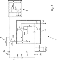
- Fig. 1 shows a block diagram of a well-known from the prior art analog current output module 1.
- the current output module 1 sets the current I on a current loop 2 and a two-wire line.
- the field device or here the meter consisting of sensor S and a control / evaluation unit 6, connected to a remote evaluation / output unit.
- Field devices or here measuring devices for determining or monitoring a process variable in automation technology capture the process variable and transmit the acquired measured values via the current loop 2 or a digital communication to a receiving unit, eg the evaluation / output unit mentioned above.
- the current I flowing through the current loop 2 is adjusted via a current controller 5 and a current setting unit 7 such that the set current I uniquely and with high accuracy represents the determined process or manipulated variable.
- the automation technology uses the 4-20mA standard.
- a current of 4 mA in the current loop represents e.g. the minimum value of the process variable and a current of 20 mA, e.g. the maximum value of the process variable.
- the 4-20mA technology is largely immune to interference, it is used in potentially explosive atmospheres and is often used in industrial applications.
- Automation technology has established the so-called two-wire technology, in which not only the measured or manipulated values are transmitted via the current loop 2, but also via which the sensor / actuator is also supplied with energy.
- only limited power is available to the field device for the measuring / setting task. This power depends on the supply voltage and the current representing the current measured value / setpoint.
- conventional field devices are dimensioned so that they get along with the minimum available power, ie they need for the measuring or Actuating only the power at minimum current and voltage. If more power is available, this additional power is usually converted into a power sink 4 in power loss.
- FIG. 1 shown current output module 1 is implemented for example in a 4-20mA transmitter, ie in the electronics part, a field device.
- the current output module 1 sets the current I, which flows through the current loop 2.
- the current I is represented by the voltage source V1 and the resistor R1 - to the left of the positive terminal 3a and the negative terminal 3b.
- the voltage source V5 represents the setpoint value of the current loop control 5.
- the transistor Q2 of the current setting unit 7 controls the current flowing from the positive terminal 3a to the current sink 4.
- the current sink 4 is at reference potential, preferably at ground GND.
- the current flows to the negative terminal 3b via the measuring resistor R12.
- a voltage between the negative terminal and ground GND is generated, which is proportional to the flowing current.
- This voltage is used as a reference voltage to control the transistor Q2 and thus to adjust the current in the current loop 2.
- the regulation of the set current takes place via the current loop control 5.
- the core of the current loop control 5 is the operational amplifier U2A.
- the operational amplifier U2A controls the transistor Q1 and also the transistor Q2 such that the sum of the voltages at the positive output of the operational amplifier U2A is equal to zero. If this condition is satisfied, the current I through the measuring resistor R12 and in the current loop 2 is proportional to the desired value, which is represented by the voltage V5.
- the current sink 4 serves to derive the power that is not required by the field device, to ground GND and thus in power loss convert. If the power supply of the field device via a separate power line, the current sink 4 can be omitted, or it can be replaced by a short circuit.
- Fig. 2 shows a schematic representation of the field device according to the invention with a sensor S, triple redundant measurement channels MK1, MK2, Mk3, triply redundant Stromeinstellkanälen IK1, IK2, IK3 and triple redundant Voterkanälen VK1, VK2, Vk3.
- the voter V comprises the Voterkanäle VK1, VK2, VK3, wherein the Voterkanälen VK1, VK2, VK3 at least parts of the comparator stages 11.1, 11.2, 11.3, the error detection stages 10.1, 10.2, 10.3 and the Ausschalttryn 9.1, 9.2, 9.3 assigned.
- the redundant analog current interface 8 includes the Stromeinstellkanäle IK1, IK2, IK3 and the Voterkanäle VK1, VK2, VK3.
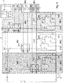
- Fig. 3 shows a preferred embodiment of a deployable in the field device according to the invention redundant power interface 8 with safe redundant voter V.
- the field device according to the invention and in particular the analog current interface 8 are designed so that they meet the high security requirements in a desired safety-critical application, eg SIL 3.
- the voltage V1 and the resistor R1 represent the voltage supply, via which the 4-20mA current loop 2 is supplied with energy.
- the power supply is integrated into a remotely located output / evaluation unit, eg a PLC.
- the control / evaluation unit 6 the output signals supplied by the sensor S V5, V8, V4 - in the case of a sensor S represent the output signals V5, V8, V4 in particular measured values - along at least three redundant and / or diversely designed measuring channels MK1, MK2 , MK3 recycles and evaluates.
- the output signals supplied by the sensor S V5, V8, V4 - in the case of a sensor S represent the output signals V5, V8, V4 in particular measured values - along at least three redundant and / or diversely designed measuring channels MK1, MK2 , MK3 recycles and evaluates.
- FIG. 3 shown essential components of the current interface 8 according to the invention are shown in the following figures Fig. 4-7 shown and described in detail.
- the analog redundant power interface 8 is in Fig. 4 shown and described in detail in an enlarged view.
- the setpoints for the control of the transistors Q2, Q4, Q7 by the three parallel-connected current loop controls 5.1, 5.2, 5.3 correspond to the output signals V5, V8, V4 of the three not separately in Fig. 4 shown measuring channels MK1, MK2, MK3. Via the transistors Q2, Q4, Q7, the current is controlled, which is converted in the current sink 4 in power loss.
- the operational amplifiers U2A, U3A, U4A of the current loop controls 5.1, 5.2, 5.3 are each assigned their own power supply VCC1, VCC2, VCC3.
- This embodiment has the advantage that if one of the power supplies fails, no total failure of the field device occurs.
- the output current I flowing in the current loop 2 is automatically given via the current setting channel IK in which the largest current is set.
- the circuit is, so to speak, designed so that the Stromeinstellkanal IK wins with the largest set current.
- the field device according to the invention has the accuracy of the measuring channel MK, which processes and evaluates the measured values / setting values with the least accuracy.
- this measuring channel is the analogously designed measuring channel MK.
- each current setting channel IK1, IK2, IK3 or each current setting unit 7.1, 7.2, 7.3 is assigned an opening stage 9.1, 9.2, 9.3.
- the switch-off stages 9.1, 9.2, 9.3 are in Fig. 5 in addition to the current regulations 5.1, 5.2, 5.3 and the Stromeinstellein pulp 7.1, 7.2, 7.3 shown.
- the turn-off stages 9.1, 9.2, 9.3 are controlled by the voter V by the signals A, B, C, D, E, F.
- the turn-off stages 9.1, 9.2, 9.3 are configured twice in each of the measuring / Stromeinstellkanal MK, IK redundant, since the voter V is twice redundant in each of the measuring / Stromeinstellkanäle MK, IK is formed.
- Each switch-off stage 9.1, 9.2, 9.3 preferably consists of simple transistors Q9, Q10; Q12, Q13; Q14, Q15, which interrupt the control signal, and thus the base current of the current regulation transistors Q2, Q4, Q7. Once the base current is interrupted, transistor Q2, Q4, Q7 is open, and no current flows in current loop 2.
- the two remaining current adjustment channels IK in this case seamlessly take over the function of current adjustment on current loop 2; the adjustment of the current on the current loop 2 takes place automatically via one of the remaining current setting channels IK.
- the output signals of the operational amplifiers U2A, U3A, U4A are used.
- the corresponding output signals are in the figures Fig. 5 and Fig. 6 marked Ch1, Ch2, Ch3.
- each Stromeinstellkanal IK1, IK2, IK3 a Voterkanal VK1, VK2, VK3 assigned.
- Each Voterkanal VK1, VK2, VK3 is part of the dual redundant Voters V and consists of a comparator 11.1, 11.2, 11.3 and an error detection stage 10.1, 10.2, 10.3.
- Each comparator stage 11 has two comparator modules 12, which in turn have two comparators 18 and two voltage dividers 16. Since the signals supplied to the comparators 18 are analog signals, the comparators 18 must also be designed as analog components. This has the advantage that a malfunction Fch is detected immediately after its occurrence and switching over to one of the remaining current adjustment channels IK can likewise take place without a time delay. This ensures a seamless transition and thus a continuous operation of the field device.
- Each comparator module 12 consists, as already stated, of two analog comparators 18 and two voltage dividers 16.
- the tolerance given in a comparison of the accuracies of the channels essentially corresponds to the accuracy of the measuring channel MK with the lowest accuracy.
- the tolerance is preferably one percent of the current measured value.
- the measuring channel MK with the lowest accuracy is in principle the analog measuring channel MK.
- the output of a comparator stage 11 signals the difference between two signals which is greater than 1%.
- the comparator stages 11 are connected to the error detection stages 10, which detect in which of the measuring or Stromeinstellkanäle MK, IK a malfunction has occurred. For example, if (Ch1 ⁇ Ch2) ⁇ (Ch1 ⁇ Ch3), then the malfunction has occurred in channel IK1.
- the fault detection stage 10.1 controls the corresponding turn-off stage 9.1 such that the power control unit 7.1 of the channel IK1, in which the malfunction is present, is overridden.
- the voter V is designed twice redundant.
- the voter V allows the reliable detection of a malfunction Fch occurring in one of the current setting channels IK even in the case where the malfunction Fch occurs in a component of the voter V, that is, either in the comparator stage 11, the error detection stage 10, or in the turn-off stage 9 of each Stromeinstellkanals IK. If any component in one of the current adjustment channels IK fails, the adjustment function is taken over by one of the remaining current adjustment channels IK - the functionality of the field device is thus ensured even if a malfunction occurs in one of the current adjustment channels IK.
- the invention also detects errors that occur in the upstream measurement channels MK.
- the analogously configured dual-redundant voter V is designed such that it continues to operate in a channel IK even if the power supply fails. Thus, the field device remains operational. If a voltage supply fails, then current regulation 5 / current setting unit 7 of the affected channel IK fails. The function of the affected channel IK is taken over by one of the remaining channels IK. Since the error detection stage 10 of a channel IK receives information from the comparators 12 of the other channels IK, it is important that a channel IK does not affect the other channels IK when the voltage is lost. Therefore, the fault detection unit 10 is provided with pull-down resistors 13.
- Each pull-down resistor 13 is connected between a signal line and ground potential and causes the signal to be set at a defined level when a current setting channel IK is turned off and the control fails due to turning off a current setting channel IK. As long as the controller is working properly, the pull-down resistors 13 have no effect on the signal since they are relatively high-impedance. The pull-down resistors 13 ensure that a properly operating current adjustment channel IK is not turned off when the power supply in one of the other current adjustment channels IK fails.
- voltage monitoring elements are provided in each current adjustment channel IK, which detect over- or under-voltages. A voltage monitoring element can switch off the power supply of the affected Stromeinstellkanals IK in case of malfunction.
- Each Voterkanal VK comprises a part of the comparator stage 11, a part of the error detection stages 10 and a part of the Ausschaltcut 9.
- Each Voterkanal VK is designed as an integrated part of the associated measurement channel MK and the associated Stromeinstellkanals IK.
- the comparator stage 11.1 has two comparator modules 12 which compare the output signals Ch1 of the associated Stromeinstellkanals IK1 with the output signals Ch2, Ch3 of the remaining Stromeinstellkanäle IK2, IK3.
- the output signals of the two comparators 18 of each of the comparator modules 12 form the input signals for the downstream NAND gate 22.1 and the downstream NAND gate 22.2.
- the output signals F, E of the NAND gate 22.1 and the NAND gate 22.2 are fed to the error detection stage 10.1.
- the error detection stage 10.1 connected downstream of the comparator stage 11.1, it is determined in which of the measurement or current setting channels MK, IK a malfunction has occurred.
- the error detection stages 10.1, 10.2, 10.3 are in each case a logic stage which is composed of two NAND gates 15.1, 15.2. In the following, let's take a closer look at the first Voter channel VK1: At the inputs of the first NAND gate 15.2 are the output signals E, F of the comparator stage 11.1 of the first Voter channel VK1. The first Voterkanal VK1 is assigned to the first measuring channel MK1.
- the redundant output signals B, D of the comparator stages 11.2, 11.3 of the second VOTerkanals VK2 and the third Voterkanals VK3 are at the inputs of the second NAND gate 15.1.
- the output signals of the first NAND gate 15.2 and the second NAND gate 15.1 form the control signals for the downstream shutdown 9.1. As long as at least one input signal of the first NAND gate 15.2 and at least one input signal of the second NAND gate 15.1 are in the logic "0" state, this does not happen. As soon as both input signals of the first NAND gate 15.2 or both input signals of the second NAND gate 15.1 are in the logic "1" state, the corresponding current setting channel IK1 is switched off directly by the corresponding switch-off stage 9.1. The same applies to the two other Stromeinstellkanäle VK2, VK3.
- control / evaluation unit 6 is configured as dynamically reconfigurable or reconfigurable or simply as FPGA, and if two channels MK, IK are implemented in the FPGA, then two channels MK, IK are connected to one power supply. Therefore, the power supply from a single channel MK, IK can not be switched off.
- the alarm current module 14 is designed such that it can detect multiple malfunctions Fch in different measurement channels MK or current adjustment channels IK.
- the alarm current module 14 corresponds to a fourth current setting channel IK4, which can be triggered to set a fault current of ⁇ 22 mA, the so-called alarm current.
- the triggering is done by the controller 20 for the alarm current control 19. Since this alarm current in a 4-20mA current loop is greater than all other currents flowing in the analog current interface 8, it automatically takes over the control.
- the alarm power module 14 is preferably powered by its own power supply VCC4.
- the alarm power module 14 may also be triggered by other modules, such as by a voltage monitor or by reconfiguration controls. These embodiments are in Figure 7 not shown separately.
- the signals of the error detection stages 10 are preferably forwarded to the reconfiguration controller, which causes the reconfiguration of the faulty measurement channels MK. These are shown and described in the already mentioned above DE 10 2012 106 652.3 in the figures Fig. 1 . Fig. 2 and Fig. 3 , The essential differences with respect to the present invention are that the voter V in the present invention is implemented in the analog power interface 8 and that the power interface 8 is redundant.
Landscapes
- Physics & Mathematics (AREA)
- General Physics & Mathematics (AREA)
- Engineering & Computer Science (AREA)
- Automation & Control Theory (AREA)
- Safety Devices In Control Systems (AREA)
Claims (15)
- Appareil de terrain destiné à la détermination ou la surveillance d'une grandeur de process dans la technique d'automatisation, l'appareil de terrain répondant à une norme de sécurité exigée par une utilisation prédéfinie, critique en terme de sécurité, lequel appareil de terrain comprend un capteur, qui fonctionne d'après un principe de mesure défini, ainsi qu'une unité de contrôle / d'exploitation (6), qui traite et exploite les données de mesure fournies par le capteur le long d'au moins trois voies de mesure (MK) conçues de manière redondante et/ou diversitaire, et une interface de courant analogique (8) étant prévue, par l'intermédiaire de laquelle un courant représentant la grandeur de process est réglable via une ligne bifilaire,
l'interface de courant analogique (8) étant conçue à triple redondance et les composants suivants étant attribués à l'interface de courant analogique (8) :- trois voies de réglage de courant (IK) couplées en parallèle, par l'intermédiaire desquelles le courant représentant la grandeur de process est réglé via la ligne bifilaire,- un dispositif de décision (V) à double redondance, qui détecte un dysfonctionnement (Fch) dans l'une des voies de mesure (MK) et/ou dans l'une des voies de réglage de courant (IK),- un étage de coupure (9) à double redondance, par l'intermédiaire duquel une voie de mesure (MK) ou une voie de réglage de courant (IK) est coupée lorsque le dispositif de décision (V) détecte un dysfonctionnement dans la voie de mesure (MK) ou dans la voie de réglage de courant (IK). - Appareil de terrain selon la revendication 1,
pour lequel chacune des voies de réglage de courant (IK) comporte une unité de réglage de courant (7) et une régulation de courant (5) et
l'unité de réglage de courant (7) et la régulation de courant (5) sont couplés en parallèle. - Appareil de terrain selon la revendication 1,
pour lequel le dispositif de décision (V) est constitué de plusieurs composants, qui sont conçus au moins partiellement ou en totalité avec une double redondance. - Appareil de terrain selon l'une ou plusieurs revendications 1 à 3,
pour lequel le dispositif de décision (V) est un dispositif de décision majoritaire, qui présente plusieurs voies de dispositif de décision (VK), chacune des voies de dispositif de décision (VK) comportant les composants suivants :un étage de comparateur (11), par l'intermédiaire duquel les signaux de sortie (Ch1, Ch2, Ch3), fournis par les différentes voies de réglage de courant (IK), sont comparés entre eux,un étage de détection d'erreur (10), qui détecte - grâce à une combinaison appropriée des signaux de sortie (A, B, C, D, E, F) des étages de comparateur (11) attribués aux voies de dispositif de décision (VK) - un dysfonctionnement (Fch) apparaissant dans une voie de mesure (MK) ou dans une voie de réglage de courant (IK) etun étage de coupure (9), qui coupe la voie de réglage de courant (IK), dans laquelle l'étage de détection d'erreur (10) détecte un dysfonctionnement. - Appareil de terrain selon la revendication 4,
pour lequel chaque voie de dispositif de décision (VK) comprend une partie de l'étage de comparateur (11), une partie de l'unité de détection d'erreur (10) et une partie de l'étage de coupure (9), et pour lequel chaque voie de dispositif de décision (VK) est conçue comme partie intégrante de la voie de mesure (MK) correspondante et de la voie de réglage de courant (IK) correspondante. - Appareil de terrain selon l'une ou plusieurs revendications 4 ou 5,
pour lequel l'étage de comparateur (11) présente pour chaque voie de dispositif de décision (VK) deux modules comparateurs (12), qui comparent les signaux de sortie (Ch1, Ch2, Ch3) de la voie de réglage de courant (IK) correspondante avec les signaux de sortie (Ch1, Ch2, Ch3) des voies de réglage de courant (IK) restantes. - Appareil de terrain selon la revendication 5,
pour lequel il s'agit, concernant les étages de détection d'erreur (10), respectivement d'un étage logique constitué de deux portes NON ET (15), les signaux de sortie des comparateurs (12) d'une première voie de dispositif de décision (VK1) étant appliqués aux entrées de la première porte NON ET (15.2), laquelle première voie est attribuée à une voie de mesure (MK1) sélectionnée, et les signaux de sortie des comparateurs (12) de la deuxième voie de dispositif (VK2) et de la troisième voie de dispositif de décision (VK3), lesquels signaux sont redondants par rapport aux entrées de la première porte NON ET (15.2), étant appliqués à la deuxième porte NON ET (15.1), et les signaux de sortie de la première porte NON ET (15.2) et de la deuxième porte NON ET (15.1) formant les signaux de commande pour l'étage de coupure (9) aval. - Appareil de terrain selon l'une ou plusieurs revendications 1 à 7,
pour lequel chaque voie de mesure (MK) / voie de réglage de courant (IK) se voit attribuer une propre alimentation de tension (U). - Appareil de terrain selon l'une ou plusieurs des revendications précédentes, pour lequel est prévu un module de courant d'alarme (14), lequel est conçu de telle sorte à délivrer un courant de défaut (22 mA) en cas d'apparition d'un dysfonctionnement (Fch) simultanément dans au moins deux voies de mesure (MK) ou dans au moins deux voies de réglage de courant (IK).
- Appareil de terrain selon l'une ou plusieurs des revendications précédentes,
pour lequel l'unité de contrôle / d'exploitation (6) est conçue, avec les voies de mesure (MK) / voies de réglage de courant (IK), les composants correspondants du dispositif de décision (V) ou les voies de dispositif de décision (VK), au moins partiellement en tant que composant logique reconfigurable avec plusieurs modules de fonction reconfigurables, partiellement de façon dynamique, dans les voies de mesure (MK) / voies de réglage de courant (IK). - Appareil de terrain selon l'une ou plusieurs des revendications précédentes,
pour lequel une commande de reconfiguration configure les modules de fonction dans les voies de mesure (MK) ou les voies de réglage de courant (IK) en fonction de l'utilisation définie, critique en terme de sécurité, de telle sorte que l'appareil de terrain réponde soit conforme au standard de sécurité exigé. - Appareil de terrain selon l'une ou plusieurs des revendications précédentes,
pour lequel la commande de reconfiguration se voit attribuer au moins un microprocesseur (17), qui reconfigure, en partie de façon dynamique, les modules de fonction d'une voie de mesure (MK) ou une voie de réglage de courant (IK), dans laquelle une erreur est détectée. - Appareil de terrain selon l'une ou plusieurs des revendications précédentes, pour lequel l'une des voies de mesure (MK) ou voies de réglage de courant (IK) est configurée sur une base analogique dans un composant FPAA.
- Appareil de terrain selon l'une ou plusieurs des revendications précédentes, pour lequel les différentes voies de mesure (MK) ou voies de réglage de courant (IK) sont espacées les unes par rapport aux autres de telle sorte qu'un changement de température et/ou de tension dans une voie de mesure (MK) ou une voie de réglage de courant (IK) n'a/n'ont aucune influence sur une voie de mesure (MK) ou voie de réglage de courant (IK) voisine.
- Appareil de terrain selon l'une ou plusieurs des revendications précédentes, notamment selon la revendication 12,
pour lequel l'au moins un microprocesseur (17) est configuré de façon permanente dans une zone statique du composant logique (FPGA).
Applications Claiming Priority (3)
| Application Number | Priority Date | Filing Date | Title |
|---|---|---|---|
| DE102012111518 | 2012-11-28 | ||
| DE102013100159.9A DE102013100159A1 (de) | 2012-11-28 | 2013-01-09 | Feldgerät zur Bestimmung oder Überwachung einer Prozessgröße in der Automatisierungstechnik |
| PCT/EP2013/072566 WO2014082806A1 (fr) | 2012-11-28 | 2013-10-29 | Appareil de terrain permettant de déterminer ou de surveiller une grandeur de processus en technique d'automatisation |
Publications (2)
| Publication Number | Publication Date |
|---|---|
| EP2926203A1 EP2926203A1 (fr) | 2015-10-07 |
| EP2926203B1 true EP2926203B1 (fr) | 2019-08-21 |
Family
ID=50679124
Family Applications (1)
| Application Number | Title | Priority Date | Filing Date |
|---|---|---|---|
| EP13783587.2A Active EP2926203B1 (fr) | 2012-11-28 | 2013-10-29 | Appareil de terrain permettant de déterminer ou de surveiller une grandeur de processus en technique d'automatisation |
Country Status (4)
| Country | Link |
|---|---|
| US (1) | US10078313B2 (fr) |
| EP (1) | EP2926203B1 (fr) |
| DE (1) | DE102013100159A1 (fr) |
| WO (1) | WO2014082806A1 (fr) |
Cited By (1)
| Publication number | Priority date | Publication date | Assignee | Title |
|---|---|---|---|---|
| US20240035853A1 (en) * | 2020-12-09 | 2024-02-01 | Vega Grieshaber Kg | Method for detecting erroneous measurement signal outputs from a field device, detection system and field device |
Families Citing this family (4)
| Publication number | Priority date | Publication date | Assignee | Title |
|---|---|---|---|---|
| DE102013101579A1 (de) | 2013-02-18 | 2014-08-21 | Endress + Hauser Gmbh + Co. Kg | Feldgerät zur Bestimmung oder Überwachung einer Prozessgröße in der Automatisierungstechnik |
| EP3336624B1 (fr) * | 2016-12-19 | 2019-02-06 | Siemens Aktiengesellschaft | Système comprenant deux modules redondants se surveillant mutuellement |
| CN106840715B (zh) * | 2017-02-13 | 2019-11-29 | 中国铁道科学研究院 | 列车转向架失稳检测传感器检测系统及方法 |
| CN109358488A (zh) * | 2018-09-04 | 2019-02-19 | 南宁学院 | 一种高容错的传感器冗余控制系统 |
Family Cites Families (14)
| Publication number | Priority date | Publication date | Assignee | Title |
|---|---|---|---|---|
| US3725818A (en) * | 1971-09-15 | 1973-04-03 | Elliott Bros | Voter circuits for three-channel redundant systems |
| US4590579A (en) * | 1983-10-04 | 1986-05-20 | Ramsey Engineering Company | Apparatus and method for digital specific gravity measurement |
| US5252134A (en) * | 1991-05-31 | 1993-10-12 | Stauffer Craig M | Integrated delivery system for chemical vapor from non-gaseous sources for semiconductor processing |
| US5428769A (en) * | 1992-03-31 | 1995-06-27 | The Dow Chemical Company | Process control interface system having triply redundant remote field units |
| DE19517492B4 (de) * | 1995-05-12 | 2004-04-29 | Bosch Rexroth Ag | Analoge Stromschnittstelle |
| DE10234303A1 (de) * | 2002-07-26 | 2004-02-19 | Endress + Hauser Gmbh + Co. Kg | Vorrichtung zur Bestimmung und/oder Überwachung einer physikalischen oder chemischen Prozeßgröße |
| US7130703B2 (en) * | 2003-04-08 | 2006-10-31 | Fisher-Rosemount Systems, Inc. | Voter logic block including operational and maintenance overrides in a process control system |
| DE102007054672A1 (de) * | 2007-11-14 | 2009-05-20 | Endress + Hauser Gmbh + Co. Kg | Feldgerät zur Bestimmung oder Überwachung einer Prozessgröße in der Prozessautomatisierung |
| KR100980043B1 (ko) * | 2008-10-22 | 2010-09-06 | 한국전력기술 주식회사 | Fpga를 이용한 발전소 보호 시스템 및 보호 방법 |
| US8209591B2 (en) * | 2008-10-23 | 2012-06-26 | Intersil Americas Inc. | Voter tester for redundant systems |
| DE102009026785A1 (de) | 2009-01-30 | 2010-08-05 | Endress + Hauser Gmbh + Co. Kg | Feldgerät zur Bestimmung und/oder Überwachung einer physikalischen oder chemischen Prozessgröße |
| DE102009028938A1 (de) * | 2009-08-27 | 2011-03-03 | Endress + Hauser Gmbh + Co. Kg | Feldgerät zur Bestimmung oder Überwachung einer physikalischen oder chemischen Variablen |
| CA2707373A1 (fr) * | 2010-06-14 | 2011-12-14 | Ievgenii Bakhmach | Procede et plate-forme pour la mise en oeuvre de systemes critiques de securite |
| DE102012106652A1 (de) | 2012-07-23 | 2014-01-23 | Endress + Hauser Gmbh + Co. Kg | Feldgerät zur Bestimmung oder Überwachung einer Prozessgröße in der Automatisierungstechnik |
-
2013
- 2013-01-09 DE DE102013100159.9A patent/DE102013100159A1/de not_active Withdrawn
- 2013-10-29 WO PCT/EP2013/072566 patent/WO2014082806A1/fr not_active Ceased
- 2013-10-29 EP EP13783587.2A patent/EP2926203B1/fr active Active
- 2013-10-29 US US14/647,506 patent/US10078313B2/en active Active
Non-Patent Citations (1)
| Title |
|---|
| None * |
Cited By (1)
| Publication number | Priority date | Publication date | Assignee | Title |
|---|---|---|---|---|
| US20240035853A1 (en) * | 2020-12-09 | 2024-02-01 | Vega Grieshaber Kg | Method for detecting erroneous measurement signal outputs from a field device, detection system and field device |
Also Published As
| Publication number | Publication date |
|---|---|
| DE102013100159A1 (de) | 2014-05-28 |
| WO2014082806A1 (fr) | 2014-06-05 |
| US10078313B2 (en) | 2018-09-18 |
| US20150316899A1 (en) | 2015-11-05 |
| EP2926203A1 (fr) | 2015-10-07 |
Similar Documents
| Publication | Publication Date | Title |
|---|---|---|
| EP2210151B1 (fr) | Appareil de champ pour déterminer ou surveiller une variable de processus dans l'automatisation des processus | |
| EP2926203B1 (fr) | Appareil de terrain permettant de déterminer ou de surveiller une grandeur de processus en technique d'automatisation | |
| EP1860513A2 (fr) | Circuit destiné à la transmission sécurisée d'une valeur de signal analogique | |
| EP2981868B1 (fr) | Système de commande et de transmission de données, dispositif de traitement et procédé de commande de processus redondante à redondance décentralisée | |
| EP3069202A1 (fr) | Commande de sécurité à entrées configurables | |
| DE102009028938A1 (de) | Feldgerät zur Bestimmung oder Überwachung einer physikalischen oder chemischen Variablen | |
| EP3538962B1 (fr) | Procédé d'analyse de dysfonctionnements dans une installation de l'automatisation de processus | |
| DE102009026785A1 (de) | Feldgerät zur Bestimmung und/oder Überwachung einer physikalischen oder chemischen Prozessgröße | |
| EP2498270A1 (fr) | Relais de sécurité et système de communication orienté vers la sécurité | |
| EP2591402B1 (fr) | Appareil de terrain pour la détermination ou la surveillance d'une grandeur de processus physique ou chimique | |
| DE102008032823B4 (de) | Sichere Anschlussvorrichtung | |
| EP2875408A1 (fr) | Appareil de champ pour la détermination ou la surveillance d'une grandeur de processus dans la technique de l'automatisation | |
| EP3336624B1 (fr) | Système comprenant deux modules redondants se surveillant mutuellement | |
| EP2701019B1 (fr) | Procédé de paramétrage d'un appareil de terrain, appareil de terrain correspondant et système de paramétrage | |
| EP3470939B1 (fr) | Procédé et système de surveillance de l'intégrité de sécurité d'une fonction de sécurité fournie par un système de sécurité | |
| WO2014124792A1 (fr) | Appareil de terrain pour application relevant de la sécurité, comprenant des canaux de mesure redondants dans un fpga | |
| EP3200033B1 (fr) | Systeme comprenant au moins deux unites peripheriques et un capteur | |
| WO2008125526A1 (fr) | Procédé de surveillance d'un réseau de la technique d'automatisation de processus | |
| DE102009002734A1 (de) | Feldgerät zur Bestimmung oder Überwachung einer Prozessgröße in der Prozessautomatisierung | |
| EP3509316A1 (fr) | Réseau de sécurité et capteur de sécurité | |
| DE102017123222A1 (de) | Verfahren zum Betreiben einer Anlage der Automatisierungstechnik | |
| EP1119802A1 (fr) | Dispositif permettant de commander et/ou de surveiller des processus industriels externes | |
| EP3557338B1 (fr) | Procédé de programmation d'une commande de sécurité |
Legal Events
| Date | Code | Title | Description |
|---|---|---|---|
| PUAI | Public reference made under article 153(3) epc to a published international application that has entered the european phase |
Free format text: ORIGINAL CODE: 0009012 |
|
| 17P | Request for examination filed |
Effective date: 20150520 |
|
| AK | Designated contracting states |
Kind code of ref document: A1 Designated state(s): AL AT BE BG CH CY CZ DE DK EE ES FI FR GB GR HR HU IE IS IT LI LT LU LV MC MK MT NL NO PL PT RO RS SE SI SK SM TR |
|
| AX | Request for extension of the european patent |
Extension state: BA ME |
|
| RIN1 | Information on inventor provided before grant (corrected) |
Inventor name: GIRARDEY, ROMUALD |
|
| DAX | Request for extension of the european patent (deleted) | ||
| STAA | Information on the status of an ep patent application or granted ep patent |
Free format text: STATUS: EXAMINATION IS IN PROGRESS |
|
| 17Q | First examination report despatched |
Effective date: 20170929 |
|
| RAP1 | Party data changed (applicant data changed or rights of an application transferred) |
Owner name: ENDRESS+HAUSER SE+CO. KG |
|
| GRAP | Despatch of communication of intention to grant a patent |
Free format text: ORIGINAL CODE: EPIDOSNIGR1 |
|
| STAA | Information on the status of an ep patent application or granted ep patent |
Free format text: STATUS: GRANT OF PATENT IS INTENDED |
|
| INTG | Intention to grant announced |
Effective date: 20190418 |
|
| GRAS | Grant fee paid |
Free format text: ORIGINAL CODE: EPIDOSNIGR3 |
|
| GRAA | (expected) grant |
Free format text: ORIGINAL CODE: 0009210 |
|
| STAA | Information on the status of an ep patent application or granted ep patent |
Free format text: STATUS: THE PATENT HAS BEEN GRANTED |
|
| AK | Designated contracting states |
Kind code of ref document: B1 Designated state(s): AL AT BE BG CH CY CZ DE DK EE ES FI FR GB GR HR HU IE IS IT LI LT LU LV MC MK MT NL NO PL PT RO RS SE SI SK SM TR |
|
| REG | Reference to a national code |
Ref country code: GB Ref legal event code: FG4D Free format text: NOT ENGLISH |
|
| REG | Reference to a national code |
Ref country code: CH Ref legal event code: EP |
|
| REG | Reference to a national code |
Ref country code: DE Ref legal event code: R096 Ref document number: 502013013425 Country of ref document: DE |
|
| REG | Reference to a national code |
Ref country code: AT Ref legal event code: REF Ref document number: 1170450 Country of ref document: AT Kind code of ref document: T Effective date: 20190915 |
|
| REG | Reference to a national code |
Ref country code: IE Ref legal event code: FG4D Free format text: LANGUAGE OF EP DOCUMENT: GERMAN |
|
| REG | Reference to a national code |
Ref country code: LT Ref legal event code: MG4D |
|
| REG | Reference to a national code |
Ref country code: NL Ref legal event code: MP Effective date: 20190821 |
|
| PG25 | Lapsed in a contracting state [announced via postgrant information from national office to epo] |
Ref country code: HR Free format text: LAPSE BECAUSE OF FAILURE TO SUBMIT A TRANSLATION OF THE DESCRIPTION OR TO PAY THE FEE WITHIN THE PRESCRIBED TIME-LIMIT Effective date: 20190821 Ref country code: NL Free format text: LAPSE BECAUSE OF FAILURE TO SUBMIT A TRANSLATION OF THE DESCRIPTION OR TO PAY THE FEE WITHIN THE PRESCRIBED TIME-LIMIT Effective date: 20190821 Ref country code: BG Free format text: LAPSE BECAUSE OF FAILURE TO SUBMIT A TRANSLATION OF THE DESCRIPTION OR TO PAY THE FEE WITHIN THE PRESCRIBED TIME-LIMIT Effective date: 20191121 Ref country code: LT Free format text: LAPSE BECAUSE OF FAILURE TO SUBMIT A TRANSLATION OF THE DESCRIPTION OR TO PAY THE FEE WITHIN THE PRESCRIBED TIME-LIMIT Effective date: 20190821 Ref country code: PT Free format text: LAPSE BECAUSE OF FAILURE TO SUBMIT A TRANSLATION OF THE DESCRIPTION OR TO PAY THE FEE WITHIN THE PRESCRIBED TIME-LIMIT Effective date: 20191223 Ref country code: NO Free format text: LAPSE BECAUSE OF FAILURE TO SUBMIT A TRANSLATION OF THE DESCRIPTION OR TO PAY THE FEE WITHIN THE PRESCRIBED TIME-LIMIT Effective date: 20191121 Ref country code: SE Free format text: LAPSE BECAUSE OF FAILURE TO SUBMIT A TRANSLATION OF THE DESCRIPTION OR TO PAY THE FEE WITHIN THE PRESCRIBED TIME-LIMIT Effective date: 20190821 Ref country code: FI Free format text: LAPSE BECAUSE OF FAILURE TO SUBMIT A TRANSLATION OF THE DESCRIPTION OR TO PAY THE FEE WITHIN THE PRESCRIBED TIME-LIMIT Effective date: 20190821 |
|
| PG25 | Lapsed in a contracting state [announced via postgrant information from national office to epo] |
Ref country code: IS Free format text: LAPSE BECAUSE OF FAILURE TO SUBMIT A TRANSLATION OF THE DESCRIPTION OR TO PAY THE FEE WITHIN THE PRESCRIBED TIME-LIMIT Effective date: 20191221 Ref country code: RS Free format text: LAPSE BECAUSE OF FAILURE TO SUBMIT A TRANSLATION OF THE DESCRIPTION OR TO PAY THE FEE WITHIN THE PRESCRIBED TIME-LIMIT Effective date: 20190821 Ref country code: AL Free format text: LAPSE BECAUSE OF FAILURE TO SUBMIT A TRANSLATION OF THE DESCRIPTION OR TO PAY THE FEE WITHIN THE PRESCRIBED TIME-LIMIT Effective date: 20190821 Ref country code: ES Free format text: LAPSE BECAUSE OF FAILURE TO SUBMIT A TRANSLATION OF THE DESCRIPTION OR TO PAY THE FEE WITHIN THE PRESCRIBED TIME-LIMIT Effective date: 20190821 Ref country code: GR Free format text: LAPSE BECAUSE OF FAILURE TO SUBMIT A TRANSLATION OF THE DESCRIPTION OR TO PAY THE FEE WITHIN THE PRESCRIBED TIME-LIMIT Effective date: 20191122 Ref country code: LV Free format text: LAPSE BECAUSE OF FAILURE TO SUBMIT A TRANSLATION OF THE DESCRIPTION OR TO PAY THE FEE WITHIN THE PRESCRIBED TIME-LIMIT Effective date: 20190821 |
|
| PG25 | Lapsed in a contracting state [announced via postgrant information from national office to epo] |
Ref country code: TR Free format text: LAPSE BECAUSE OF FAILURE TO SUBMIT A TRANSLATION OF THE DESCRIPTION OR TO PAY THE FEE WITHIN THE PRESCRIBED TIME-LIMIT Effective date: 20190821 |
|
| PG25 | Lapsed in a contracting state [announced via postgrant information from national office to epo] |
Ref country code: DK Free format text: LAPSE BECAUSE OF FAILURE TO SUBMIT A TRANSLATION OF THE DESCRIPTION OR TO PAY THE FEE WITHIN THE PRESCRIBED TIME-LIMIT Effective date: 20190821 Ref country code: EE Free format text: LAPSE BECAUSE OF FAILURE TO SUBMIT A TRANSLATION OF THE DESCRIPTION OR TO PAY THE FEE WITHIN THE PRESCRIBED TIME-LIMIT Effective date: 20190821 Ref country code: RO Free format text: LAPSE BECAUSE OF FAILURE TO SUBMIT A TRANSLATION OF THE DESCRIPTION OR TO PAY THE FEE WITHIN THE PRESCRIBED TIME-LIMIT Effective date: 20190821 Ref country code: PL Free format text: LAPSE BECAUSE OF FAILURE TO SUBMIT A TRANSLATION OF THE DESCRIPTION OR TO PAY THE FEE WITHIN THE PRESCRIBED TIME-LIMIT Effective date: 20190821 |
|
| PG25 | Lapsed in a contracting state [announced via postgrant information from national office to epo] |
Ref country code: SM Free format text: LAPSE BECAUSE OF FAILURE TO SUBMIT A TRANSLATION OF THE DESCRIPTION OR TO PAY THE FEE WITHIN THE PRESCRIBED TIME-LIMIT Effective date: 20190821 Ref country code: SK Free format text: LAPSE BECAUSE OF FAILURE TO SUBMIT A TRANSLATION OF THE DESCRIPTION OR TO PAY THE FEE WITHIN THE PRESCRIBED TIME-LIMIT Effective date: 20190821 Ref country code: MC Free format text: LAPSE BECAUSE OF FAILURE TO SUBMIT A TRANSLATION OF THE DESCRIPTION OR TO PAY THE FEE WITHIN THE PRESCRIBED TIME-LIMIT Effective date: 20190821 Ref country code: IS Free format text: LAPSE BECAUSE OF FAILURE TO SUBMIT A TRANSLATION OF THE DESCRIPTION OR TO PAY THE FEE WITHIN THE PRESCRIBED TIME-LIMIT Effective date: 20200224 Ref country code: CZ Free format text: LAPSE BECAUSE OF FAILURE TO SUBMIT A TRANSLATION OF THE DESCRIPTION OR TO PAY THE FEE WITHIN THE PRESCRIBED TIME-LIMIT Effective date: 20190821 |
|
| REG | Reference to a national code |
Ref country code: CH Ref legal event code: PL |
|
| REG | Reference to a national code |
Ref country code: DE Ref legal event code: R097 Ref document number: 502013013425 Country of ref document: DE |
|
| PLBE | No opposition filed within time limit |
Free format text: ORIGINAL CODE: 0009261 |
|
| STAA | Information on the status of an ep patent application or granted ep patent |
Free format text: STATUS: NO OPPOSITION FILED WITHIN TIME LIMIT |
|
| PG2D | Information on lapse in contracting state deleted |
Ref country code: IS |
|
| PG25 | Lapsed in a contracting state [announced via postgrant information from national office to epo] |
Ref country code: LU Free format text: LAPSE BECAUSE OF NON-PAYMENT OF DUE FEES Effective date: 20191029 Ref country code: CH Free format text: LAPSE BECAUSE OF NON-PAYMENT OF DUE FEES Effective date: 20191031 Ref country code: LI Free format text: LAPSE BECAUSE OF NON-PAYMENT OF DUE FEES Effective date: 20191031 |
|
| 26N | No opposition filed |
Effective date: 20200603 |
|
| REG | Reference to a national code |
Ref country code: BE Ref legal event code: MM Effective date: 20191031 |
|
| PG25 | Lapsed in a contracting state [announced via postgrant information from national office to epo] |
Ref country code: SI Free format text: LAPSE BECAUSE OF FAILURE TO SUBMIT A TRANSLATION OF THE DESCRIPTION OR TO PAY THE FEE WITHIN THE PRESCRIBED TIME-LIMIT Effective date: 20190821 Ref country code: BE Free format text: LAPSE BECAUSE OF NON-PAYMENT OF DUE FEES Effective date: 20191031 |
|
| GBPC | Gb: european patent ceased through non-payment of renewal fee |
Effective date: 20191121 |
|
| PG25 | Lapsed in a contracting state [announced via postgrant information from national office to epo] |
Ref country code: IE Free format text: LAPSE BECAUSE OF NON-PAYMENT OF DUE FEES Effective date: 20191029 Ref country code: GB Free format text: LAPSE BECAUSE OF NON-PAYMENT OF DUE FEES Effective date: 20191121 |
|
| REG | Reference to a national code |
Ref country code: AT Ref legal event code: MM01 Ref document number: 1170450 Country of ref document: AT Kind code of ref document: T Effective date: 20191029 |
|
| PG25 | Lapsed in a contracting state [announced via postgrant information from national office to epo] |
Ref country code: AT Free format text: LAPSE BECAUSE OF NON-PAYMENT OF DUE FEES Effective date: 20191029 |
|
| PG25 | Lapsed in a contracting state [announced via postgrant information from national office to epo] |
Ref country code: CY Free format text: LAPSE BECAUSE OF FAILURE TO SUBMIT A TRANSLATION OF THE DESCRIPTION OR TO PAY THE FEE WITHIN THE PRESCRIBED TIME-LIMIT Effective date: 20190821 |
|
| PG25 | Lapsed in a contracting state [announced via postgrant information from national office to epo] |
Ref country code: HU Free format text: LAPSE BECAUSE OF FAILURE TO SUBMIT A TRANSLATION OF THE DESCRIPTION OR TO PAY THE FEE WITHIN THE PRESCRIBED TIME-LIMIT; INVALID AB INITIO Effective date: 20131029 Ref country code: MT Free format text: LAPSE BECAUSE OF FAILURE TO SUBMIT A TRANSLATION OF THE DESCRIPTION OR TO PAY THE FEE WITHIN THE PRESCRIBED TIME-LIMIT Effective date: 20190821 |
|
| PG25 | Lapsed in a contracting state [announced via postgrant information from national office to epo] |
Ref country code: MK Free format text: LAPSE BECAUSE OF FAILURE TO SUBMIT A TRANSLATION OF THE DESCRIPTION OR TO PAY THE FEE WITHIN THE PRESCRIBED TIME-LIMIT Effective date: 20190821 |
|
| P01 | Opt-out of the competence of the unified patent court (upc) registered |
Effective date: 20230601 |
|
| PGFP | Annual fee paid to national office [announced via postgrant information from national office to epo] |
Ref country code: IT Payment date: 20231026 Year of fee payment: 11 Ref country code: FR Payment date: 20231026 Year of fee payment: 11 |
|
| PG25 | Lapsed in a contracting state [announced via postgrant information from national office to epo] |
Ref country code: FR Free format text: LAPSE BECAUSE OF NON-PAYMENT OF DUE FEES Effective date: 20241031 |
|
| PG25 | Lapsed in a contracting state [announced via postgrant information from national office to epo] |
Ref country code: IT Free format text: LAPSE BECAUSE OF NON-PAYMENT OF DUE FEES Effective date: 20241029 |
|
| PGFP | Annual fee paid to national office [announced via postgrant information from national office to epo] |
Ref country code: DE Payment date: 20251021 Year of fee payment: 13 |