EP2926465B1 - Transfert inductif d'énergie sans fil - Google Patents
Transfert inductif d'énergie sans fil Download PDFInfo
- Publication number
- EP2926465B1 EP2926465B1 EP13795515.9A EP13795515A EP2926465B1 EP 2926465 B1 EP2926465 B1 EP 2926465B1 EP 13795515 A EP13795515 A EP 13795515A EP 2926465 B1 EP2926465 B1 EP 2926465B1
- Authority
- EP
- European Patent Office
- Prior art keywords
- power
- transmitter
- receiver
- control error
- signal
- Prior art date
- Legal status (The legal status is an assumption and is not a legal conclusion. Google has not performed a legal analysis and makes no representation as to the accuracy of the status listed.)
- Active
Links
Images


Classifications
-
- H—ELECTRICITY
- H04—ELECTRIC COMMUNICATION TECHNIQUE
- H04B—TRANSMISSION
- H04B5/00—Near-field transmission systems, e.g. inductive or capacitive transmission systems
- H04B5/70—Near-field transmission systems, e.g. inductive or capacitive transmission systems specially adapted for specific purposes
- H04B5/79—Near-field transmission systems, e.g. inductive or capacitive transmission systems specially adapted for specific purposes for data transfer in combination with power transfer
-
- H—ELECTRICITY
- H02—GENERATION; CONVERSION OR DISTRIBUTION OF ELECTRIC POWER
- H02J—ELECTRIC POWER NETWORKS; CIRCUIT ARRANGEMENTS OR SYSTEMS FOR SUPPLYING OR DISTRIBUTING ELECTRIC POWER; SYSTEMS FOR STORING ELECTRIC ENERGY
- H02J50/00—Circuit arrangements or systems for wireless supply or distribution of electric power
- H02J50/10—Circuit arrangements or systems for wireless supply or distribution of electric power using inductive coupling
- H02J50/12—Circuit arrangements or systems for wireless supply or distribution of electric power using inductive coupling of the resonant type
-
- H—ELECTRICITY
- H02—GENERATION; CONVERSION OR DISTRIBUTION OF ELECTRIC POWER
- H02J—ELECTRIC POWER NETWORKS; CIRCUIT ARRANGEMENTS OR SYSTEMS FOR SUPPLYING OR DISTRIBUTING ELECTRIC POWER; SYSTEMS FOR STORING ELECTRIC ENERGY
- H02J50/00—Circuit arrangements or systems for wireless supply or distribution of electric power
- H02J50/80—Circuit arrangements or systems for wireless supply or distribution of electric power involving the exchange of data, concerning supply or distribution of electric power, between transmitting devices and receiving devices
-
- H—ELECTRICITY
- H04—ELECTRIC COMMUNICATION TECHNIQUE
- H04B—TRANSMISSION
- H04B5/00—Near-field transmission systems, e.g. inductive or capacitive transmission systems
- H04B5/20—Near-field transmission systems, e.g. inductive or capacitive transmission systems characterised by the transmission technique; characterised by the transmission medium
- H04B5/24—Inductive coupling
- H04B5/26—Inductive coupling using coils
- H04B5/266—One coil at each side, e.g. with primary and secondary coils
-
- H—ELECTRICITY
- H02—GENERATION; CONVERSION OR DISTRIBUTION OF ELECTRIC POWER
- H02J—ELECTRIC POWER NETWORKS; CIRCUIT ARRANGEMENTS OR SYSTEMS FOR SUPPLYING OR DISTRIBUTING ELECTRIC POWER; SYSTEMS FOR STORING ELECTRIC ENERGY
- H02J7/00—Circuit arrangements for charging or discharging batteries or for supplying loads from batteries
- H02J7/40—Circuit arrangements for charging or discharging batteries or for supplying loads from batteries characterised by the exchange of charge or discharge related data
- H02J7/42—Circuit arrangements for charging or discharging batteries or for supplying loads from batteries characterised by the exchange of charge or discharge related data with electronic devices having internal batteries, e.g. mobile phones
-
- H—ELECTRICITY
- H04—ELECTRIC COMMUNICATION TECHNIQUE
- H04B—TRANSMISSION
- H04B5/00—Near-field transmission systems, e.g. inductive or capacitive transmission systems
- H04B5/40—Near-field transmission systems, e.g. inductive or capacitive transmission systems characterised by components specially adapted for near-field transmission
- H04B5/45—Transponders
Definitions
- Power transmission via magnetic induction is a well-known concept, mostly applied in transformers, having a tight coupling between primary transmitter coil and a secondary receiver coil.
- transformers having a tight coupling between primary transmitter coil and a secondary receiver coil.
- wireless power transfer between these becomes possible based on the principle of a loosely coupled transformer.
- This may in many embodiments provide a particularly advantageous way for the power transmitter to provide a response to a query message from the power receiver. It may allow effective, reliable and/or low complexity detection at the power receiver. A particular advantage is that detection may be improved and/or facilitated.
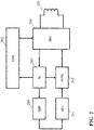
- the driver 201 is coupled to a power transmitter controller 203 which comprises various control functionality for operating the power transfer function, and which in the specific example is arranged to operate the power transmitter 101 in accordance with the Qi standard.
- the power transmitter controller 203 may be arranged to perform the Identification and Configuration as well as the power transfer phases of the Qi standard.
- the system is furthermore arranged to sometimes temporarily deviate from this operation and to set the power of the power signal differently than requested by the power control error messages from the power receiver 105
- This deviation is performed in response to receiving a query message from the power receiver 105 and constitutes a reply to the query message.
- the deviation in how the power transmitter 101 responds to one or more power control error messages provides an indication to the power receiver 105 of a response to the query message.
- the approach introduces bidirectional communication to a power transfer system, such as a Qi system, but without requiring separate communication functionality and without additional modulation of the power signal. Rather, a temporary variation in the response to power control error messages is used to communicate from the power transmitter 101 to the power receiver 105.
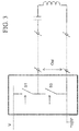
- the power receiver 105 comprises a sense processor 511 which is arranged to monitor power variations in the power signal. Specifically, the sense processor 511 may sense the inductor current and voltage of the receiver coil 107 and may detect when the power transmitter 101 changes the power of the power signal and thus the flux affecting the receiver coil 107.
- the power receiver 105 can detect that the power signal changes corresponding to requests of the power control error messages and thus that the response to the query message is negative. It should be noted that the actual changes to the power signal are not pre-determined or can be assumed in advance. Rather, they are given by the requests of the power control error messages and the resulting variations on the power signal depend both on the power control error messages and on the message being communicated. The actual changes in the power level that indicate a negative reply depend on the power requests contained in the power control error messages, and are through this dependency also dependent on the current operating conditions, and specifically on the current power level of the power signal and on the load conditions. The power signal impact is thus not predetermined as for conventional modulation of the power signal.
- the response may be provided during the power transfer phase.
- power control may for example be introduced earlier, such as during the configuration phase.
Landscapes
- Engineering & Computer Science (AREA)
- Computer Networks & Wireless Communication (AREA)
- Power Engineering (AREA)
- Signal Processing (AREA)
- Near-Field Transmission Systems (AREA)
- Charge And Discharge Circuits For Batteries Or The Like (AREA)
- Control Of Conveyors (AREA)
Claims (16)
- Transmetteur de puissance (101) pour transférer de la puissance à un récepteur de puissance (105) en utilisant un signal de puissance inductive sans fil, le transmetteur de puissance (101) comprenant :un inducteur (103) pour fournir le signal de puissance ;un générateur de signal de puissance (207) pour commander à l'inducteur (103) de fournir le signal de puissance ;un récepteur (213) pour recevoir des messages de données du récepteur de puissance (105), les messages de données étant communiqués par modulation de charge du signal de puissance ;un dispositif de commande de boucle de puissance (207) agencé pour commander une puissance du signal de puissance en réponse aux messages d'erreurs de commande de puissance reçus du récepteur de puissance (105) ;un processeur de message d'interrogation (209) pour détecter qu'un message d'interrogation a été reçu du récepteur de puissance (105) ; etun processeur de modification (211) pour modifier, au cours d'une phase de transfert de puissance, une réponse du dispositif de commande de boucle de puissance (207) aux messages d'erreurs de commande de puissance en réponse au message d'interrogation.
- Transmetteur de puissance selon la revendication 1, dans lequel le processeur de modification (211) est agencé pour ignorer au moins un message de commande d'erreur en réponse au message d'interrogation.
- Transmetteur de puissance selon la revendication 1, dans lequel les messages d'erreurs de commande de puissance indiquent une demande de changement de puissance du signal de puissance et le processeur de modification (211) est agencé pour modifier une réponse pour au moins un message d'erreur de commande de puissance en changeant une puissance du signal de puissance dans un sens opposé à celui demandé par le au moins un message d'erreur de commande de puissance.
- Transmetteur de puissance selon la revendication 1, 2 ou 3, dans lequel le premier processeur est agencé pour modifier les réponses aux messages d'erreurs de commande de puissance conformément à un premier motif de modifications à des réponses aux messages d'erreurs de commande de puissance.
- Transmetteur de puissance selon la revendication 4, dans lequel le premier processeur est agencé pour sélectionner le premier motif parmi une pluralité de motifs de modifications aux réponses aux messages d'erreurs de commande de puissance en réponse au message d'interrogation, chaque motif de la pluralité de motifs correspondant à une réponse différente au message d'interrogation.
- Transmetteur de puissance selon la revendication 4 ou 5, dans lequel le premier motif comprend au moins une modification correspondant à aucun changement de puissance du signal de puissance et au moins une modification correspondant au changement de la puissance du signal de puissance conformément à la demande du message d'erreur de commande de puissance.
- Transmetteur de puissance selon la revendication 1, dans lequel le message d'interrogation comprend une indication d'une modification souhaitée de la réponse du dispositif de commande de boucle de puissance aux messages d'erreurs de commande de puissance correspondant à une réponse au message d'interrogation.
- Transmetteur de puissance selon la revendication 1, dans lequel le processeur de modification (211) est agencé pour changer la puissance du signal de puissance en changeant un courant inducteur.
- Transmetteur de puissance selon la revendication 1, dans lequel le message d'interrogation comprend une identification de dispositif et le processeur de modification (211) est agencé pour modifier la réponse en fonction de l'identification du dispositif.
- Transmetteur de puissance selon la revendication 1, dans lequel le message d'interrogation comprend une indication d'une spécification technique à laquelle répond le récepteur de puissance et le processeur de modification (211) est agencé pour modifier la réponse en fonction de l'indication d'une spécification technique.
- Transmetteur de puissance selon la revendication 1, dans lequel le message d'interrogation est compris dans un message de configuration transmis avant l'initialisation d'une phase de transfert de puissance.
- Transmetteur de puissance selon la revendication 1, dans lequel la modification dépend en outre d'une capacité du transmetteur de puissance.
- Récepteur de puissance (105) pour recevoir de la puissance d'un transmetteur de puissance (101) en utilisant un signal de puissance inductive sans fil, le récepteur de puissance (105) comprenant :un inducteur (107) pour recevoir le signal de puissance ;un transmetteur (505) pour transmettre des messages de données au transmetteur de puissance (101), les messages de données étant communiqués par modulation de charge du signal de puissance ;un processeur de message d'interrogation (509) pour transmettre un message d'interrogation au transmetteur de puissance (101) ;un dispositif de commande de boucle de puissance (507) pour transmettre des messages d'erreurs de commande de puissance au transmetteur de puissance (101), au moins certains des messages d'erreurs de commande de puissance nécessitant un changement dans une puissance du signal de puissance ;un moniteur de signal de puissance (511) pour surveiller les variations de puissance du signal de puissance ; etun processeur de réponse (513) pour déterminer, au cours d'une phase de transfert de puissance, une réponse au message d'interrogation en réponse à une comparaison des variations de puissance du signal de puissance et des variations de puissance demandées par les messages d'erreurs de commande de puissance.
- Système de transfert de puissance comprenant un transmetteur de puissance (101) selon la revendication 1 et un récepteur de puissance (105) selon la revendication 13.
- Procédé de fonctionnement pour un transmetteur de puissance (101) agencé pour transférer de la puissance à un récepteur de puissance (105) en utilisant un signal de puissance inductive sans fil, le transmetteur de puissance (101) comprenant un inducteur (103) pour fournir le signal de puissance et un générateur de signal de puissance (207) pour commande à l'inducteur (103) de fournir le signal de puissance ; le procédé comprenant :la réception de messages de données du récepteur de puissance (105), les messages de données étant communiqués par modulation de charge du signal de puissance ;la commande d'une puissance du signal de puissance en réponse aux messages d'erreurs de commande de puissance reçus du récepteur de puissance (105) ;la détection qu'un message d'interrogation a été reçu du récepteur de puissance (105) ; etla modification, au cours d'une phase de transfert de puissance, d'une réponse aux messages d'erreurs de commande de puissance en réponse au message d'interrogation.
- Procédé de fonctionnement pour un récepteur de puissance (105) agencé pour recevoir de la puissance d'un transmetteur de puissance (101) en utilisant un signal de puissance inductive sans fil, le récepteur de puissance (105) comprenant un inducteur (107) pour recevoir le signal de puissance ; le procédé comprenant :la transmission d'un message d'interrogation au transmetteur de puissance (101) par modulation de charge du signal de puissance ;la transmission de messages d'erreurs de commande de puissance au transmetteur de puissance (101) par modulation de charge du signal de puissance, au moins certains des messages d'erreurs de commande de puissance nécessitant un changement d'une puissance du signal de puissance ;la surveillance de variations de puissance dans le signal de puissance ; etla détermination, au cours d'une phase de transfert de puissance, d'une réponse au message d'interrogation en réponse à une comparaison des variations de puissance dans le signal de puissance et des variations de puissance nécessitées par les messages d'erreurs de commande de puissance.
Priority Applications (1)
| Application Number | Priority Date | Filing Date | Title |
|---|---|---|---|
| EP13795515.9A EP2926465B1 (fr) | 2012-11-29 | 2013-11-26 | Transfert inductif d'énergie sans fil |
Applications Claiming Priority (3)
| Application Number | Priority Date | Filing Date | Title |
|---|---|---|---|
| EP12194763 | 2012-11-29 | ||
| EP13795515.9A EP2926465B1 (fr) | 2012-11-29 | 2013-11-26 | Transfert inductif d'énergie sans fil |
| PCT/EP2013/074784 WO2014083015A1 (fr) | 2012-11-29 | 2013-11-26 | Transfert de puissance inductive sans fil |
Publications (2)
| Publication Number | Publication Date |
|---|---|
| EP2926465A1 EP2926465A1 (fr) | 2015-10-07 |
| EP2926465B1 true EP2926465B1 (fr) | 2020-02-12 |
Family
ID=47594324
Family Applications (1)
| Application Number | Title | Priority Date | Filing Date |
|---|---|---|---|
| EP13795515.9A Active EP2926465B1 (fr) | 2012-11-29 | 2013-11-26 | Transfert inductif d'énergie sans fil |
Country Status (8)
| Country | Link |
|---|---|
| US (2) | US10771112B2 (fr) |
| EP (1) | EP2926465B1 (fr) |
| JP (1) | JP6371775B2 (fr) |
| CN (1) | CN104798315B (fr) |
| BR (1) | BR112015012074B1 (fr) |
| MX (1) | MX352471B (fr) |
| RU (1) | RU2658331C2 (fr) |
| WO (1) | WO2014083015A1 (fr) |
Families Citing this family (37)
| Publication number | Priority date | Publication date | Assignee | Title |
|---|---|---|---|---|
| EP2845416B1 (fr) | 2012-05-02 | 2018-11-21 | Apple Inc. | Procédés de détection et d'identification d'un récepteur dans un système de transfert de puissance inductif |
| KR102283473B1 (ko) | 2012-11-05 | 2021-08-02 | 애플 인크. | 유도 결합된 전력 전송 시스템 |
| JP6081207B2 (ja) * | 2013-01-29 | 2017-02-15 | 三洋電機株式会社 | 無接点給電システム、受電機器、給電台、無接点給電方法 |
| US20150091508A1 (en) * | 2013-10-01 | 2015-04-02 | Blackberry Limited | Bi-directional communication with a device under charge |
| JP6824737B2 (ja) | 2013-11-13 | 2021-02-03 | アップル インコーポレイテッドApple Inc. | 誘導電力伝送システムのための送信器 |
| US10283995B2 (en) * | 2014-02-28 | 2019-05-07 | L'oreal | Charge current monitoring or control in a resonance-tuned inductive charger |
| WO2015178781A1 (fr) | 2014-05-19 | 2015-11-26 | Powerbyproxi Limited | Noyau magnétiquement perméable et agencement de bobine de transfert de puissance inductive |
| US10269486B2 (en) | 2014-05-19 | 2019-04-23 | Apple Inc. | Magnetically permeable core and inductive power transfer coil arrangement |
| EP3158621A4 (fr) | 2014-06-20 | 2017-07-12 | PowerbyProxi Limited | Détection d'objet étranger dans un champ de transfert de puissance inductive |
| KR102285941B1 (ko) | 2014-08-12 | 2021-08-06 | 애플 인크. | 전력 전달을 위한 시스템 및 방법 |
| KR20160080499A (ko) * | 2014-12-29 | 2016-07-08 | 엘지이노텍 주식회사 | 무선 전력 송신 장치 및 이를 포함하는 무선충전 시스템 |
| US9805580B2 (en) * | 2015-01-23 | 2017-10-31 | Visteon Global Technologies, Inc. | Initiating an alert based on a mobile device being left behind |
| EP3254352A4 (fr) | 2015-02-03 | 2017-12-13 | PowerbyProxi Limited | Émetteur de puissance inductif |
| US10566853B2 (en) | 2015-02-03 | 2020-02-18 | Apple Inc. | Inductive power transmitter |
| KR102191406B1 (ko) | 2015-03-04 | 2020-12-16 | 애플 인크. | 유도 전력 전송기 |
| CN107529346B (zh) | 2015-04-02 | 2021-03-02 | 苹果公司 | 感应电力发射器 |
| EP3375068B1 (fr) * | 2015-11-09 | 2019-05-15 | Koninklijke Philips N.V. | Transfert inductif d'énergie sans fil |
| CN108401471B (zh) | 2015-11-19 | 2021-06-25 | 苹果公司 | 感应式电力发射器 |
| JP6700470B2 (ja) | 2016-04-04 | 2020-05-27 | アップル インコーポレイテッドApple Inc. | 誘導電力送信機 |
| WO2017204663A1 (fr) | 2016-05-25 | 2017-11-30 | Powerbyproxi Limited | Agencement de bobine |
| WO2017209630A1 (fr) | 2016-06-01 | 2017-12-07 | Powerbyproxi Limited | Joint électrique à transfert sans fil |
| WO2017213032A1 (fr) * | 2016-06-06 | 2017-12-14 | 株式会社村田製作所 | Système d'alimentation électrique sans fil, dispositif de transmission d'énergie sans fil, et dispositif de réception d'énergie sans fil |
| CN206834025U (zh) | 2016-11-18 | 2018-01-02 | 鲍尔拜普罗克西有限公司 | 感应式电力传输线圈组件 |
| US10978911B2 (en) | 2016-12-19 | 2021-04-13 | Apple Inc. | Inductive power transfer system |
| KR102601200B1 (ko) | 2017-03-07 | 2023-11-09 | 파워매트 테크놀로지스 엘티디. | 무선 전력 충전 시스템 |
| KR102561310B1 (ko) | 2017-03-07 | 2023-07-27 | 파워매트 테크놀로지스 엘티디. | 무선 전력 충전 시스템 |
| JP7278217B2 (ja) | 2017-03-07 | 2023-05-19 | パワーマット テクノロジーズ リミテッド | 無線電力充電用のシステム |
| US11218025B2 (en) | 2017-03-07 | 2022-01-04 | Powermat Technologies Ltd. | System for wireless power charging |
| EP3509186A1 (fr) * | 2018-01-03 | 2019-07-10 | Koninklijke Philips N.V. | Commande de puissance dans un système de transfert de puissance sans fil |
| US10593468B2 (en) | 2018-04-05 | 2020-03-17 | Apple Inc. | Inductive power transfer assembly |
| US10826169B2 (en) | 2019-01-03 | 2020-11-03 | Apple Inc. | Radio frequency remote head front-end circuitry systems and methods |
| EP3787151A1 (fr) * | 2019-08-27 | 2021-03-03 | Koninklijke Philips N.V. | Émetteur de puissance, système et procédé associés |
| EP3790159A1 (fr) | 2019-09-09 | 2021-03-10 | Koninklijke Philips N.V. | Transfert de puissance sans fil |
| US11081911B1 (en) * | 2020-08-21 | 2021-08-03 | Apple Inc. | Enhanced wireless power transfer |
| CN114233110B (zh) * | 2021-12-06 | 2023-04-21 | 河北省天然气有限责任公司沙河分公司 | 一种用于智能井盖的锁定装置 |
| US12024088B2 (en) | 2022-10-28 | 2024-07-02 | Voxx International Corporation | Lighting system for vehicle cupholder with inductive power coupling and related methods |
| EP4686040A1 (fr) * | 2024-07-24 | 2026-01-28 | Koninklijke Philips N.V. | Transfert d'énergie sans fil |
Family Cites Families (10)
| Publication number | Priority date | Publication date | Assignee | Title |
|---|---|---|---|---|
| JP5124991B2 (ja) * | 2006-05-30 | 2013-01-23 | ソニー株式会社 | 通信システム、通信装置、通信方法、並びにプログラム |
| US8234509B2 (en) | 2008-09-26 | 2012-07-31 | Hewlett-Packard Development Company, L.P. | Portable power supply device for mobile computing devices |
| NZ593720A (en) | 2009-01-06 | 2014-03-28 | Access Business Group Int Llc | Wireless charging system with device power compliance |
| JP2010183704A (ja) * | 2009-02-04 | 2010-08-19 | Seiko Epson Corp | 受電制御装置、受電装置、送電制御装置、送電装置及び電子機器 |
| JP5554937B2 (ja) * | 2009-04-22 | 2014-07-23 | パナソニック株式会社 | 非接触給電システム |
| KR20110103297A (ko) * | 2010-03-12 | 2011-09-20 | 삼성전자주식회사 | 무선 전력 충전 방법 및 장치 |
| PL2628233T3 (pl) | 2010-10-13 | 2020-06-01 | Koninklijke Philips N.V. | Nadajnik energii i odbiornik energii dla indukcyjnego systemu zasilania |
| WO2012129273A1 (fr) * | 2011-03-22 | 2012-09-27 | Access Business Group International Llc | Système et procédé de commande améliorée dans systèmes d'alimentation électrique sans fil |
| MX2014003598A (es) | 2011-09-30 | 2014-04-25 | Koninkl Philips Nv | Transferencia de energia inductiva inalambrica. |
| WO2014001983A1 (fr) | 2012-06-29 | 2014-01-03 | Koninklijke Philips N.V. | Transfert sans fil de puissance inductive |
-
2013
- 2013-11-26 BR BR112015012074-1A patent/BR112015012074B1/pt active IP Right Grant
- 2013-11-26 WO PCT/EP2013/074784 patent/WO2014083015A1/fr not_active Ceased
- 2013-11-26 JP JP2015544444A patent/JP6371775B2/ja active Active
- 2013-11-26 EP EP13795515.9A patent/EP2926465B1/fr active Active
- 2013-11-26 RU RU2015125515A patent/RU2658331C2/ru active
- 2013-11-26 MX MX2015006567A patent/MX352471B/es active IP Right Grant
- 2013-11-26 CN CN201380062433.3A patent/CN104798315B/zh active Active
- 2013-11-26 US US14/441,308 patent/US10771112B2/en active Active
-
2020
- 2020-04-07 US US16/841,950 patent/US11139859B2/en active Active
Non-Patent Citations (1)
| Title |
|---|
| None * |
Also Published As
| Publication number | Publication date |
|---|---|
| JP6371775B2 (ja) | 2018-08-08 |
| US10771112B2 (en) | 2020-09-08 |
| WO2014083015A1 (fr) | 2014-06-05 |
| US11139859B2 (en) | 2021-10-05 |
| JP2016503645A (ja) | 2016-02-04 |
| BR112015012074A2 (pt) | 2017-07-11 |
| RU2015125515A (ru) | 2017-01-10 |
| RU2658331C2 (ru) | 2018-06-20 |
| CN104798315B (zh) | 2017-06-20 |
| EP2926465A1 (fr) | 2015-10-07 |
| US20200274581A1 (en) | 2020-08-27 |
| MX2015006567A (es) | 2015-08-05 |
| MX352471B (es) | 2017-11-27 |
| CN104798315A (zh) | 2015-07-22 |
| BR112015012074B1 (pt) | 2022-10-11 |
| US20150303995A1 (en) | 2015-10-22 |
Similar Documents
| Publication | Publication Date | Title |
|---|---|---|
| US11139859B2 (en) | Wireless inductive power transfer | |
| US20240056123A1 (en) | Wireless power transferring method and device therefor | |
| KR102888972B1 (ko) | 무선 전력 전달 방법 및 이를 위한 장치 | |
| US9425864B2 (en) | Wireless inductive power transfer | |
| US10396605B2 (en) | Wireless power transmitter and receiver | |
| EP3627656B1 (fr) | Émetteur de puissance, récepteur de puissance et procédé de communication pour un système d'alimentation inductive | |
| KR102145497B1 (ko) | 무선 전력 전송 방법 및 장치 | |
| EP2867997A1 (fr) | Transfert sans fil de puissance inductive | |
| CN104508935A (zh) | 无线感应式电力传输 | |
| KR20170138271A (ko) | 무선 전력 수신기의 동작 방법 및 무선 전력 송신기의 동작 방법 | |
| KR20210112529A (ko) | 전력 중계 장치 |
Legal Events
| Date | Code | Title | Description |
|---|---|---|---|
| PUAI | Public reference made under article 153(3) epc to a published international application that has entered the european phase |
Free format text: ORIGINAL CODE: 0009012 |
|
| 17P | Request for examination filed |
Effective date: 20150629 |
|
| AK | Designated contracting states |
Kind code of ref document: A1 Designated state(s): AL AT BE BG CH CY CZ DE DK EE ES FI FR GB GR HR HU IE IS IT LI LT LU LV MC MK MT NL NO PL PT RO RS SE SI SK SM TR |
|
| AX | Request for extension of the european patent |
Extension state: BA ME |
|
| DAX | Request for extension of the european patent (deleted) | ||
| STAA | Information on the status of an ep patent application or granted ep patent |
Free format text: STATUS: EXAMINATION IS IN PROGRESS |
|
| 17Q | First examination report despatched |
Effective date: 20190329 |
|
| REG | Reference to a national code |
Ref country code: DE Ref legal event code: R079 Ref document number: 602013065746 Country of ref document: DE Free format text: PREVIOUS MAIN CLASS: H04B0005000000 Ipc: H02J0050120000 |
|
| GRAP | Despatch of communication of intention to grant a patent |
Free format text: ORIGINAL CODE: EPIDOSNIGR1 |
|
| STAA | Information on the status of an ep patent application or granted ep patent |
Free format text: STATUS: GRANT OF PATENT IS INTENDED |
|
| RIC1 | Information provided on ipc code assigned before grant |
Ipc: H02J 50/80 20160101ALI20190730BHEP Ipc: H02J 50/12 20160101AFI20190730BHEP Ipc: H02J 7/02 20160101ALI20190730BHEP |
|
| INTG | Intention to grant announced |
Effective date: 20190816 |
|
| GRAS | Grant fee paid |
Free format text: ORIGINAL CODE: EPIDOSNIGR3 |
|
| GRAA | (expected) grant |
Free format text: ORIGINAL CODE: 0009210 |
|
| STAA | Information on the status of an ep patent application or granted ep patent |
Free format text: STATUS: THE PATENT HAS BEEN GRANTED |
|
| AK | Designated contracting states |
Kind code of ref document: B1 Designated state(s): AL AT BE BG CH CY CZ DE DK EE ES FI FR GB GR HR HU IE IS IT LI LT LU LV MC MK MT NL NO PL PT RO RS SE SI SK SM TR |
|
| REG | Reference to a national code |
Ref country code: GB Ref legal event code: FG4D |
|
| REG | Reference to a national code |
Ref country code: CH Ref legal event code: EP |
|
| REG | Reference to a national code |
Ref country code: AT Ref legal event code: REF Ref document number: 1233387 Country of ref document: AT Kind code of ref document: T Effective date: 20200215 |
|
| REG | Reference to a national code |
Ref country code: IE Ref legal event code: FG4D |
|
| REG | Reference to a national code |
Ref country code: DE Ref legal event code: R096 Ref document number: 602013065746 Country of ref document: DE |
|
| RAP2 | Party data changed (patent owner data changed or rights of a patent transferred) |
Owner name: KONINKLIJKE PHILIPS N.V. |
|
| PG25 | Lapsed in a contracting state [announced via postgrant information from national office to epo] |
Ref country code: NO Free format text: LAPSE BECAUSE OF FAILURE TO SUBMIT A TRANSLATION OF THE DESCRIPTION OR TO PAY THE FEE WITHIN THE PRESCRIBED TIME-LIMIT Effective date: 20200512 Ref country code: RS Free format text: LAPSE BECAUSE OF FAILURE TO SUBMIT A TRANSLATION OF THE DESCRIPTION OR TO PAY THE FEE WITHIN THE PRESCRIBED TIME-LIMIT Effective date: 20200212 Ref country code: FI Free format text: LAPSE BECAUSE OF FAILURE TO SUBMIT A TRANSLATION OF THE DESCRIPTION OR TO PAY THE FEE WITHIN THE PRESCRIBED TIME-LIMIT Effective date: 20200212 |
|
| REG | Reference to a national code |
Ref country code: LT Ref legal event code: MG4D |
|
| REG | Reference to a national code |
Ref country code: NL Ref legal event code: MP Effective date: 20200212 |
|
| PG25 | Lapsed in a contracting state [announced via postgrant information from national office to epo] |
Ref country code: GR Free format text: LAPSE BECAUSE OF FAILURE TO SUBMIT A TRANSLATION OF THE DESCRIPTION OR TO PAY THE FEE WITHIN THE PRESCRIBED TIME-LIMIT Effective date: 20200513 Ref country code: BG Free format text: LAPSE BECAUSE OF FAILURE TO SUBMIT A TRANSLATION OF THE DESCRIPTION OR TO PAY THE FEE WITHIN THE PRESCRIBED TIME-LIMIT Effective date: 20200512 Ref country code: HR Free format text: LAPSE BECAUSE OF FAILURE TO SUBMIT A TRANSLATION OF THE DESCRIPTION OR TO PAY THE FEE WITHIN THE PRESCRIBED TIME-LIMIT Effective date: 20200212 Ref country code: IS Free format text: LAPSE BECAUSE OF FAILURE TO SUBMIT A TRANSLATION OF THE DESCRIPTION OR TO PAY THE FEE WITHIN THE PRESCRIBED TIME-LIMIT Effective date: 20200612 Ref country code: SE Free format text: LAPSE BECAUSE OF FAILURE TO SUBMIT A TRANSLATION OF THE DESCRIPTION OR TO PAY THE FEE WITHIN THE PRESCRIBED TIME-LIMIT Effective date: 20200212 Ref country code: LV Free format text: LAPSE BECAUSE OF FAILURE TO SUBMIT A TRANSLATION OF THE DESCRIPTION OR TO PAY THE FEE WITHIN THE PRESCRIBED TIME-LIMIT Effective date: 20200212 |
|
| PG25 | Lapsed in a contracting state [announced via postgrant information from national office to epo] |
Ref country code: NL Free format text: LAPSE BECAUSE OF FAILURE TO SUBMIT A TRANSLATION OF THE DESCRIPTION OR TO PAY THE FEE WITHIN THE PRESCRIBED TIME-LIMIT Effective date: 20200212 |
|
| PG25 | Lapsed in a contracting state [announced via postgrant information from national office to epo] |
Ref country code: ES Free format text: LAPSE BECAUSE OF FAILURE TO SUBMIT A TRANSLATION OF THE DESCRIPTION OR TO PAY THE FEE WITHIN THE PRESCRIBED TIME-LIMIT Effective date: 20200212 Ref country code: PT Free format text: LAPSE BECAUSE OF FAILURE TO SUBMIT A TRANSLATION OF THE DESCRIPTION OR TO PAY THE FEE WITHIN THE PRESCRIBED TIME-LIMIT Effective date: 20200705 Ref country code: SK Free format text: LAPSE BECAUSE OF FAILURE TO SUBMIT A TRANSLATION OF THE DESCRIPTION OR TO PAY THE FEE WITHIN THE PRESCRIBED TIME-LIMIT Effective date: 20200212 Ref country code: SM Free format text: LAPSE BECAUSE OF FAILURE TO SUBMIT A TRANSLATION OF THE DESCRIPTION OR TO PAY THE FEE WITHIN THE PRESCRIBED TIME-LIMIT Effective date: 20200212 Ref country code: LT Free format text: LAPSE BECAUSE OF FAILURE TO SUBMIT A TRANSLATION OF THE DESCRIPTION OR TO PAY THE FEE WITHIN THE PRESCRIBED TIME-LIMIT Effective date: 20200212 Ref country code: DK Free format text: LAPSE BECAUSE OF FAILURE TO SUBMIT A TRANSLATION OF THE DESCRIPTION OR TO PAY THE FEE WITHIN THE PRESCRIBED TIME-LIMIT Effective date: 20200212 Ref country code: CZ Free format text: LAPSE BECAUSE OF FAILURE TO SUBMIT A TRANSLATION OF THE DESCRIPTION OR TO PAY THE FEE WITHIN THE PRESCRIBED TIME-LIMIT Effective date: 20200212 Ref country code: RO Free format text: LAPSE BECAUSE OF FAILURE TO SUBMIT A TRANSLATION OF THE DESCRIPTION OR TO PAY THE FEE WITHIN THE PRESCRIBED TIME-LIMIT Effective date: 20200212 Ref country code: EE Free format text: LAPSE BECAUSE OF FAILURE TO SUBMIT A TRANSLATION OF THE DESCRIPTION OR TO PAY THE FEE WITHIN THE PRESCRIBED TIME-LIMIT Effective date: 20200212 |
|
| REG | Reference to a national code |
Ref country code: DE Ref legal event code: R097 Ref document number: 602013065746 Country of ref document: DE |
|
| REG | Reference to a national code |
Ref country code: AT Ref legal event code: MK05 Ref document number: 1233387 Country of ref document: AT Kind code of ref document: T Effective date: 20200212 |
|
| PLBE | No opposition filed within time limit |
Free format text: ORIGINAL CODE: 0009261 |
|
| STAA | Information on the status of an ep patent application or granted ep patent |
Free format text: STATUS: NO OPPOSITION FILED WITHIN TIME LIMIT |
|
| 26N | No opposition filed |
Effective date: 20201113 |
|
| PG25 | Lapsed in a contracting state [announced via postgrant information from national office to epo] |
Ref country code: IT Free format text: LAPSE BECAUSE OF FAILURE TO SUBMIT A TRANSLATION OF THE DESCRIPTION OR TO PAY THE FEE WITHIN THE PRESCRIBED TIME-LIMIT Effective date: 20200212 Ref country code: AT Free format text: LAPSE BECAUSE OF FAILURE TO SUBMIT A TRANSLATION OF THE DESCRIPTION OR TO PAY THE FEE WITHIN THE PRESCRIBED TIME-LIMIT Effective date: 20200212 |
|
| PG25 | Lapsed in a contracting state [announced via postgrant information from national office to epo] |
Ref country code: PL Free format text: LAPSE BECAUSE OF FAILURE TO SUBMIT A TRANSLATION OF THE DESCRIPTION OR TO PAY THE FEE WITHIN THE PRESCRIBED TIME-LIMIT Effective date: 20200212 Ref country code: SI Free format text: LAPSE BECAUSE OF FAILURE TO SUBMIT A TRANSLATION OF THE DESCRIPTION OR TO PAY THE FEE WITHIN THE PRESCRIBED TIME-LIMIT Effective date: 20200212 |
|
| PG25 | Lapsed in a contracting state [announced via postgrant information from national office to epo] |
Ref country code: MC Free format text: LAPSE BECAUSE OF FAILURE TO SUBMIT A TRANSLATION OF THE DESCRIPTION OR TO PAY THE FEE WITHIN THE PRESCRIBED TIME-LIMIT Effective date: 20200212 |
|
| REG | Reference to a national code |
Ref country code: CH Ref legal event code: PL |
|
| PG25 | Lapsed in a contracting state [announced via postgrant information from national office to epo] |
Ref country code: LU Free format text: LAPSE BECAUSE OF NON-PAYMENT OF DUE FEES Effective date: 20201126 |
|
| REG | Reference to a national code |
Ref country code: BE Ref legal event code: MM Effective date: 20201130 |
|
| PG25 | Lapsed in a contracting state [announced via postgrant information from national office to epo] |
Ref country code: CH Free format text: LAPSE BECAUSE OF NON-PAYMENT OF DUE FEES Effective date: 20201130 Ref country code: LI Free format text: LAPSE BECAUSE OF NON-PAYMENT OF DUE FEES Effective date: 20201130 |
|
| PG25 | Lapsed in a contracting state [announced via postgrant information from national office to epo] |
Ref country code: IE Free format text: LAPSE BECAUSE OF NON-PAYMENT OF DUE FEES Effective date: 20201126 |
|
| PG25 | Lapsed in a contracting state [announced via postgrant information from national office to epo] |
Ref country code: MT Free format text: LAPSE BECAUSE OF FAILURE TO SUBMIT A TRANSLATION OF THE DESCRIPTION OR TO PAY THE FEE WITHIN THE PRESCRIBED TIME-LIMIT Effective date: 20200212 Ref country code: CY Free format text: LAPSE BECAUSE OF FAILURE TO SUBMIT A TRANSLATION OF THE DESCRIPTION OR TO PAY THE FEE WITHIN THE PRESCRIBED TIME-LIMIT Effective date: 20200212 |
|
| PG25 | Lapsed in a contracting state [announced via postgrant information from national office to epo] |
Ref country code: MK Free format text: LAPSE BECAUSE OF FAILURE TO SUBMIT A TRANSLATION OF THE DESCRIPTION OR TO PAY THE FEE WITHIN THE PRESCRIBED TIME-LIMIT Effective date: 20200212 Ref country code: AL Free format text: LAPSE BECAUSE OF FAILURE TO SUBMIT A TRANSLATION OF THE DESCRIPTION OR TO PAY THE FEE WITHIN THE PRESCRIBED TIME-LIMIT Effective date: 20200212 |
|
| PG25 | Lapsed in a contracting state [announced via postgrant information from national office to epo] |
Ref country code: BE Free format text: LAPSE BECAUSE OF NON-PAYMENT OF DUE FEES Effective date: 20201130 |
|
| PGFP | Annual fee paid to national office [announced via postgrant information from national office to epo] |
Ref country code: DE Payment date: 20251126 Year of fee payment: 13 |
|
| PGFP | Annual fee paid to national office [announced via postgrant information from national office to epo] |
Ref country code: GB Payment date: 20251125 Year of fee payment: 13 |
|
| PGFP | Annual fee paid to national office [announced via postgrant information from national office to epo] |
Ref country code: FR Payment date: 20251125 Year of fee payment: 13 |
|
| PGFP | Annual fee paid to national office [announced via postgrant information from national office to epo] |
Ref country code: TR Payment date: 20251112 Year of fee payment: 13 |