EP2926623B2 - Heizelement und prozessheizer - Google Patents
Heizelement und prozessheizer Download PDFInfo
- Publication number
- EP2926623B2 EP2926623B2 EP15705240.8A EP15705240A EP2926623B2 EP 2926623 B2 EP2926623 B2 EP 2926623B2 EP 15705240 A EP15705240 A EP 15705240A EP 2926623 B2 EP2926623 B2 EP 2926623B2
- Authority
- EP
- European Patent Office
- Prior art keywords
- heating
- tube
- heating element
- element according
- gas
- Prior art date
- Legal status (The legal status is an assumption and is not a legal conclusion. Google has not performed a legal analysis and makes no representation as to the accuracy of the status listed.)
- Active
Links
Images

Classifications
-
- H—ELECTRICITY
- H05—ELECTRIC TECHNIQUES NOT OTHERWISE PROVIDED FOR
- H05B—ELECTRIC HEATING; ELECTRIC LIGHT SOURCES NOT OTHERWISE PROVIDED FOR; CIRCUIT ARRANGEMENTS FOR ELECTRIC LIGHT SOURCES, IN GENERAL
- H05B3/00—Ohmic-resistance heating
- H05B3/40—Heating elements having the shape of rods or tubes
- H05B3/42—Heating elements having the shape of rods or tubes non-flexible
- H05B3/44—Heating elements having the shape of rods or tubes non-flexible heating conductor arranged within rods or tubes of insulating material
-
- F—MECHANICAL ENGINEERING; LIGHTING; HEATING; WEAPONS; BLASTING
- F24—HEATING; RANGES; VENTILATING
- F24H—FLUID HEATERS, e.g. WATER OR AIR HEATERS, HAVING HEAT-GENERATING MEANS, e.g. HEAT PUMPS, IN GENERAL
- F24H3/00—Air heaters
- F24H3/002—Air heaters using electric energy supply
-
- H—ELECTRICITY
- H05—ELECTRIC TECHNIQUES NOT OTHERWISE PROVIDED FOR
- H05B—ELECTRIC HEATING; ELECTRIC LIGHT SOURCES NOT OTHERWISE PROVIDED FOR; CIRCUIT ARRANGEMENTS FOR ELECTRIC LIGHT SOURCES, IN GENERAL
- H05B3/00—Ohmic-resistance heating
- H05B3/40—Heating elements having the shape of rods or tubes
- H05B3/42—Heating elements having the shape of rods or tubes non-flexible
- H05B3/48—Heating elements having the shape of rods or tubes non-flexible heating conductor embedded in insulating material
-
- H—ELECTRICITY
- H05—ELECTRIC TECHNIQUES NOT OTHERWISE PROVIDED FOR
- H05B—ELECTRIC HEATING; ELECTRIC LIGHT SOURCES NOT OTHERWISE PROVIDED FOR; CIRCUIT ARRANGEMENTS FOR ELECTRIC LIGHT SOURCES, IN GENERAL
- H05B2203/00—Aspects relating to Ohmic resistive heating covered by group H05B3/00
- H05B2203/002—Heaters using a particular layout for the resistive material or resistive elements
- H05B2203/003—Heaters using a particular layout for the resistive material or resistive elements using serpentine layout
-
- H—ELECTRICITY
- H05—ELECTRIC TECHNIQUES NOT OTHERWISE PROVIDED FOR
- H05B—ELECTRIC HEATING; ELECTRIC LIGHT SOURCES NOT OTHERWISE PROVIDED FOR; CIRCUIT ARRANGEMENTS FOR ELECTRIC LIGHT SOURCES, IN GENERAL
- H05B2203/00—Aspects relating to Ohmic resistive heating covered by group H05B3/00
- H05B2203/014—Heaters using resistive wires or cables not provided for in H05B3/54
-
- H—ELECTRICITY
- H05—ELECTRIC TECHNIQUES NOT OTHERWISE PROVIDED FOR
- H05B—ELECTRIC HEATING; ELECTRIC LIGHT SOURCES NOT OTHERWISE PROVIDED FOR; CIRCUIT ARRANGEMENTS FOR ELECTRIC LIGHT SOURCES, IN GENERAL
- H05B2203/00—Aspects relating to Ohmic resistive heating covered by group H05B3/00
- H05B2203/022—Heaters specially adapted for heating gaseous material
Definitions
- the present invention relates to a heating element for heating gases to high temperatures, comprising at least one pipe 1 designed for the flow of hot gas and an electric heating wire in the pipe, which is used to transfer heat to gas flowing past the heating wire is designed according to the preamble of claim 1.
- the present invention also relates to a process heater having a housing with a gas supply and a gas outlet, a heating space between gas supply and gas outlet for receiving a heating element and electrical connections for at least one heating element, according to the preamble of claim 15.
- Corresponding heating elements have long been known. They consist, as already mentioned, of at least one gas to be flowed through pipe, which is open on both sides for the purpose of flow, wherein in the tube, a heating wire is arranged, at which the gas flows past and heated by the direct contact with the heating wire.
- the document DE 16 15 278 A1 discloses a heating element having a helical heating wire disposed in a tube.
- heating wires helically wound, fine wires whose cross-section is much smaller than the pipe cross-section and are traversed by electricity and thereby heat.
- the electrical energy converted into heat by the heating wire naturally depends on the available electrical voltage and the resistance of corresponding heating wires, whereby the length of a coiled wire can be adapted to achieve desired resistance values or several corresponding heating wires can be connected in parallel or in series.
- the heat energy transferred to the gas flowing along the heating wire depends on the maximum temperature reached by the heating wire, on the flow velocity and on the surface available for heat exchange as well as on the exact flow conditions in the heating element.
- the maximum gas temperatures which can be reached regularly in continuous operation with such process heaters in practice, are in the order of 700 ° C.
- heating wire typically contains aluminum in small amounts, contact with oxygen initially results in the formation of a protective aluminum oxide layer around the wire.
- a large surface-to-volume ratio of the heating wires is considered advantageous for an effective transmission of the heat energy generated in the heating wire on the gas flowing past, so far the short life of such heating elements is accepted when gas temperatures in the range of 900 ° C or above.
- Process heaters and heating elements that generate gas temperatures of 900 ° C or even more, but have for the aforementioned reasons regularly only a service life of a few hours.
- the document US 4,877,990 discloses a heating element according to the preamble of claim 1 and also a process heater according to the preamble of claim 15.
- the heating elements according to D1 consists of a plurality of bores in a block of insulating material, through which central heating filaments extend in the longitudinal direction.
- the heating element serves as an air sterilizer and is intended for the generation of temperatures which amount to a maximum of 400 ° C.
- the concrete embodiment described describes a heating filament of NiCr with a resistance of 100 ⁇ / m.
- the present invention has the object to provide a process heater and a corresponding heating element, which allow a generation of gas temperatures up to 1000 ° C or even above, so that extremely large amounts of energy can transfer to the gas and still have a relatively long life , which is at least 10 times the life of conventional heating coils in the generation of gas temperatures up to 1000 ° C usually.
- the heating wire is not a coiled wire whose material cross-section is substantially smaller than that of the tube, but rather a rod, for which in turn one can define a corresponding longitudinal axis which extends substantially along or parallel to the axis of the tube and while the tube fills so far that between heating element and Pipe wall remains only a relatively small, clear distance which is a maximum of 10 mm and preferably still significantly less, even if he punctually, ie in areas less than 20% of the overlap length of pipe and heater or less than 20% of the circumference of the Heater rod make up, can be larger.
- the term "heating wire” is therefore used in the present description as a generic term for both relatively thin coiled wires and for heating rods according to the present invention, wherein the different thickness is not the primary distinguishing criterion.
- the maximum clear distance between the heating element and the tube is in many practical cases between 1 and 2 mm, slightly above or below it down to minimum values of 0.02 mm.
- the maximum diameter of the heating element is rarely over 10 mm, because even larger diameters, the efficiency of energy transfer due to a relatively large volume / surface ratio of the heating significantly decreases, which can only be partially compensated by a larger pipe and Schustabus. In principle, however, the use of heating elements with larger diameters is possible, although not preferred.
- a diameter range for heating rods apparently favorable in practice for the purposes of the present invention is between 0.5 mm and 5 mm.
- the present invention provides a minimum ratio of the cross-sectional area of the heating element to the free inner cross-section of the tube, which is in the range between 0.04 and 0.95.
- the heating element at least as far as it extends within the tube, should have a cross-sectional area which is at least 30% and more preferably at least 50% of the free tube cross-section. In specific embodiments that were tested with positive results, this aspect ratio was about 80%, wherein the maximum clear distance was 0.2 to 0.5 mm and a correspondingly uniform annular gap between the heating element and the tube wall about 0.1 to 0.25 mm was.
- tube is to be interpreted broadly in the context of the present invention and ultimately defines only one cavity with an inlet and an outlet opening, which allow a flow to be heated with gas. Not even the cross section across the length of the pipe must be constant, although this is of course preferred in order to produce a largely constant gap, in particular a constant annular gap, between the heating element and the pipe wall by simple means.
- the annular gap can be interrupted by elevations, which are distributed over the circumference on the Schustabober Diagram or on the inner surface of the tube, to allow a centering of the heating rod and to ensure a homogeneous heat transfer.
- tubes for example, through holes are considered in a solid block, such a block may have a plurality of parallel holes.
- the heating rods according to the present invention are relatively thick compared to the coiled wires in corresponding tubes of conventional heaters, they can better transfer and distribute heat internally, which helps avoid local overheating, and for that reason alone have high thermal stress High heating rod temperatures beyond 1000 ° C significantly longer life and durability or allow only the heating of gases to over 1000 ° C with metallic electric heating elements.
- the preferred proportions between the cross section of the heating element and the inner cross section of the tube are expediently in the range of 0.2 to about 0.95.
- a cross-sectional ratio of 0.2 results, for example, in a very thin heating rod diameter of 0.2 mm and a tube diameter of 0.45 mm ,.
- a cross-sectional ratio of 0.9 is obtained, for example, with a heater rod diameter of about 4.75 mm in a tube with 5 mm inner diameter, wherein it does not matter in terms of the cross-sectional ratios on the unit or on the absolute dimensions, as long as the Edelstab screenmesser within the above and below ranges.
- a preferred range of cross-sectional ratios is between 0.3 and 0.8, corresponding to a diameter ratio between about 0.5 and 0.9 with absolute diameters of the heating rods between 0.5 and 5 mm.
- the heat transfer between the heating element and the gas flowing through is surprisingly effective, so that with such a heating element readily Process gas temperatures of up to 1200 ° C or even more, while the lifetime of these process heaters and in particular the heating rods is a multiple of the life of conventional process heaters or heating wires, which are designed for the generation of gas temperatures of 900 ° C or more.
- the annular gap along the circumference of the heating element also does not necessarily have to have a constant width, but can vary between 0 (contact) and the maximum value (in the case of circular cross sections, ie twice the uniform gap width.
- the absolute pipe diameter and Wienstab preparedmesser can vary widely, for example between an inner diameter of the tube from 1 mm to 20 mm or more, z. B. 60 mm, again depending on the other dimensions, such as the length of tube and heater, the desired width of the annular gap, the gas flow rate and the electrical resistance of the heating element and the available standing tension.
- the heating rod has a correspondingly smaller diameter for small pipe diameters, and in an extreme case also 0.5 mm or less, e.g. May be 0.2 mm. He is so compared to conventional helical wires or Schufilraitn but still significantly thicker and especially not coiled, but extends parallel to the tube axis and along the tube axis.
- heating element of a heating element according to the present invention is usually also thicker than the heating wires in conventional heating elements with the same tube cross-section and a heating element in the overall comparable heating element according to the prior art.
- the heating element is arranged as accurately as possible in the center of the tube, wherein the outer cross section of the heating element substantially coincides with the shape of the inner cross section of the tube, resulting in the result that the annular gap between the heating element and the inner wall of the tube has a substantially constant width.
- the inner surface of the tube and / or the outer surface of the heating element could also be structured, i. For example, have a running in the longitudinal direction of the rod and the tube rib or groove structure, which may also have a small helix angle.
- Such superficial structures may, for a given annular gap width, expand the laminar flow region to larger gas flow rates if desired.
- the concrete width of the annular gap always represents a compromise between maximum heat energy transfer and pressure loss at the desired gas flow rate. That is, the narrower the annular gap, the more effective is the heat transfer from the heating element to the gas flowing between the heating element and the tube, with a narrow gap but also limits the gas flow and / or requires a large pressure difference between inlet and outlet.
- the reasonable width of the annular gap but also depends on the length of the tube and also from the converted in the heating element electric heating power.
- the average width of the annular gap is about 0.1 mm, in another example, 0.2 mm but it is not always possible to really concentrically arrange the heating element in a tube, so that the annular gap width at least at some axial positions in the circumferential direction can vary between zero and twice the average annular gap width.
- spacers are therefore provided at some positions along the circumference and / or over the length, which center the heating element in the tube.
- the spacers may be integrally formed with the heating element or the tube and are in particular designed so that they impede the gas flow between the heating element and the pipe as little as possible.
- the spacers are preferably made of heat-resistant ceramic and are ideally realized via the tube geometry.
- heating rod and tube are arranged coaxially with each other, d. H. their axes collapse.
- the heating element and the tube but by no means have a circular cross section, they could for example also have the cross section of a preferably equilateral polygon and it could, for example, a pipe with hexagonal or octagonal cross-section or outer contour, which receives a cylindrical heating element.
- a square or hexagonal outer contour of the tubes allows a very compact arrangement of the tube bundle and a resulting minimal bypass flow between the tubes.
- a plurality of parallel tubes are combined to form a tube package and the heating element, more precisely the heating rods of the individual tubes of the tube package have the shape of a meandering passed through the heating wire, which is inserted at the end of a tube and from the outlet side
- a tube package can consist of several groups of tubes, which are each traversed by a single continuous heating wire. Should it require the electrical connection power, a division into several electrical zones has proven, which allow a connection in delta or star connection.
- a tight packing of such tubes is arranged in a common housing, wherein between the housing wall and the outside of the dense packing of individual tubes additionally insulating material is arranged.
- the insulating material is preferably a high temperature resistant, ceramic material which has sufficient stability for the production of dimensionally stable Has tubes. Between a plurality of parallel tubes bundled together, a high-temperature resistant ceramic insulating material such as sold by the applicant under the trade name "Fibrothal" can be disposed.
- the tubes should consist of an insulating and high-temperature-resistant ceramic, which in particular aluminum oxide (Al2O3) comes into consideration.
- Al2O3 aluminum oxide
- the heating element is preferably made of an iron-chromium-aluminum alloy or of a nickel-chromium-iron alloy.
- a thicker heating rod in turn consist of a bundle of parallel, possibly also twisted together individual rods or wires, in such an embodiment, the above-defined clearance by the clearance of an envelope of the bundle of rods or wires to the inner wall of the tube is defined.
- the heating element may have a diameter in the range of 0.2 to 50 mm, preferably between 0.5 and 10 mm.
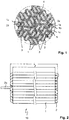
- FIG. 1 a dense packing of tubes 1 in a hexagonal arrangement, through which heating rods 2 are passed.
- the tubes 1 are made of alumina ceramic and have an inner diameter of about 1.7 mm, and an outer diameter of about 2.7 to 2.8 mm, resulting in a wall thickness of the tubes 1 of about 0.5 to 0.55 mm results.
- the heating elements are formed here by a continuous heating wire with a diameter of about 1.5 mm, which is passed alternately in opposite directions through a plurality of tubes of this tube package, wherein the heating element marked 2a, the insertion side of the heating wire in the tube 1 a marked, which is then returned through the pipe 1 b again, reintroduced into the tube 1 c and in this way passed through a plurality of tubes and substantially parallel to the axis until finally the end of the wire in the form of the heating element 2 z through the Tube 1 z exits again.
- thermocouples or other thermometers serve, while the central tube may have, for example, a centering 4, with the aid of which from the tube package and the passed heating wire existing heating element 10 can be centered in the housing of a process heater.
- FIG. 2 is a side view of the package or the hexagonal packing of tubes according to FIG. 1 ,
- the length I of the tubes 1 is, for example, between 150 and 500 mm, while the length L of the entire heating element 10 (without the protruding terminal ends 2a and 2z) is greater by approximately 4-5 mm for the dimensions of tubes 1 and heating rods 2 indicated here ,
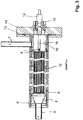
- FIG. 3 shows a complete process heater 100 with a tubular housing 6, a gas supply pipe 7, a gas outlet nozzle 9 with outlet pipe 8 and a mounting flange 13, which in turn is mounted on a power supply flange 14.
- the gas supply pipe 7 opens into a cylindrical cavity 18, through which extend two parallel power supply pipes 16, of which in the side view of FIG. 3 only one is recognizable.
- the power supply tubes form a passage for the connection of the wire ends 2a and 2z with electrical connection contacts on the electrical connection flange 14.
- the heating element 10, which consists of a tube package, for example according to FIGS. 1 and 2 is located in the center of the tubular housing 6, wherein between the inner wall of the tubular housing 6 and the heating element 10, a high temperature resistant, ceramic insulating material 17 is arranged, which typically consists of two heating elements 10 from opposite sides enclosing half shells 17a, 17b (see FIG. 5 ), whose inner contour of the outer contour of the heating element 10 is adjusted.
- the half shells can also together form a simple cylindrical tube, in which case the remaining spaces between the heating element 10 are stuffed with present in loose fiber composite insulating material, which also fills the spaces between the tubes 1, 3 otherwise.
- the gas inlet side of the heating element 10 could also have a corresponding perforated, circular cover plate whose diameter corresponds to the maximum outer diameter of the tube assembly of the heating element 10 and which has holes only at the position of the tubes or the tube openings and thus covering the entire end face of the tube package with the exception of the holes before the heating wire is passed through the tubes.
- a cover plate could consist of the same ceramic insulating material, as it is also used for the half-shells 17a, 17b between the housing and heating element 10 and which is sold by the applicant under the brand name "Fibrothal".
- the ends 2a and 2z of the heating wire (s) 2 are connected by the insulating connecting pipes 16 to external electrical terminals 12 which are mounted to the supply flange 14 via a compression fitting 11.
- the variant of a process heater shown here is designed for a Schustab- or- Walkerdraht designedmesser of about 1, 5 mm for a heating power of 3.5 kW, the clear inner tube diameter between about 1.7 and 2.2 mm can be and the heating wire or rods consist of an iron-chromium-aluminum alloy. Suitable heating wires are sold by the applicant, inter alia, under the trade name "NICROTHAL". It goes without saying that corresponding process heaters can be dimensioned arbitrarily so that the power range can extend between a few watts or a few 100 watts and 100 or more kilowatts.
- the gas to be heated is supplied through the port 7 and enters a substantially cylindrical vestibule 18, which is otherwise still traversed by the two insulating tubes 16 of the power connection and flows into the open annular gaps 5 between the tubes 1 and the heating wires 2 and through the tubes, to then exit via the nozzle 9 and the outlet tube 8 from the process heater.
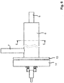
- FIG. 4 is finally after a frontal view of the process heater after FIG. 3 from the left, which in turn recognizes the nozzle 9 with the outlet end 8, as well as the housing 6, the gas supply pipe 7 and the connecting flange thirteenth
Landscapes
- Engineering & Computer Science (AREA)
- Physics & Mathematics (AREA)
- Thermal Sciences (AREA)
- Chemical & Material Sciences (AREA)
- Combustion & Propulsion (AREA)
- Mechanical Engineering (AREA)
- General Engineering & Computer Science (AREA)
- Resistance Heating (AREA)
Priority Applications (1)
| Application Number | Priority Date | Filing Date | Title |
|---|---|---|---|
| PL15705240T PL2926623T5 (pl) | 2014-02-25 | 2015-02-10 | Element grzejny i ogrzewacz procesowy |
Applications Claiming Priority (2)
| Application Number | Priority Date | Filing Date | Title |
|---|---|---|---|
| DE102014102474.5A DE102014102474A1 (de) | 2014-02-25 | 2014-02-25 | Heizelement und Prozessheizer |
| PCT/EP2015/052712 WO2015128183A1 (de) | 2014-02-25 | 2015-02-10 | Heizelement und prozessheizer |
Publications (3)
| Publication Number | Publication Date |
|---|---|
| EP2926623A1 EP2926623A1 (de) | 2015-10-07 |
| EP2926623B1 EP2926623B1 (de) | 2016-06-15 |
| EP2926623B2 true EP2926623B2 (de) | 2019-05-01 |
Family
ID=52484457
Family Applications (1)
| Application Number | Title | Priority Date | Filing Date |
|---|---|---|---|
| EP15705240.8A Active EP2926623B2 (de) | 2014-02-25 | 2015-02-10 | Heizelement und prozessheizer |
Country Status (12)
| Country | Link |
|---|---|
| US (2) | US9867232B2 (es) |
| EP (1) | EP2926623B2 (es) |
| JP (2) | JP6194115B2 (es) |
| KR (2) | KR101735817B1 (es) |
| CN (2) | CN108489087A (es) |
| CA (1) | CA2936372C (es) |
| DE (1) | DE102014102474A1 (es) |
| DK (1) | DK2926623T4 (es) |
| ES (1) | ES2586472T5 (es) |
| PL (1) | PL2926623T5 (es) |
| RU (1) | RU2669589C1 (es) |
| WO (1) | WO2015128183A1 (es) |
Cited By (3)
| Publication number | Priority date | Publication date | Assignee | Title |
|---|---|---|---|---|
| EP3873173A1 (de) | 2020-02-26 | 2021-09-01 | SunFire GmbH | Gaserhitzer-heizelement-herstellungsverfahren sowie gaserhitzer-heizelement |
| US11692738B2 (en) | 2017-12-08 | 2023-07-04 | Kanthal Gmbh | Electric fluid flow heater with heating element support member |
| US12000622B2 (en) | 2017-12-08 | 2024-06-04 | Kanthal Gmbh | Electric fluid flow heater with stabilisation brace |
Families Citing this family (34)
| Publication number | Priority date | Publication date | Assignee | Title |
|---|---|---|---|---|
| DE102014102474A1 (de) * | 2014-02-25 | 2015-08-27 | Sandvik Materials Technology Deutschland Gmbh | Heizelement und Prozessheizer |
| KR101737049B1 (ko) * | 2016-01-26 | 2017-05-17 | 조수홍 | 콤팩트 타입의 질소 가열 장치 |
| WO2019046246A1 (en) | 2017-08-28 | 2019-03-07 | Watlow Electric Manufacturing Company | HEAT EXCHANGER WITH CONTINUOUS HELICAL DEFLECTOR |
| DE102017120814A1 (de) | 2017-09-08 | 2019-03-14 | Karlsruher Institut für Technologie | Konvertierungsreaktor und Verfahrensführung |
| JP2019154554A (ja) * | 2018-03-08 | 2019-09-19 | 株式会社三洋物産 | 遊技機 |
| JP2019154555A (ja) * | 2018-03-08 | 2019-09-19 | 株式会社三洋物産 | 遊技機 |
| JP2019154556A (ja) * | 2018-03-08 | 2019-09-19 | 株式会社三洋物産 | 遊技機 |
| DE102018109643A1 (de) * | 2018-04-23 | 2019-10-24 | Eisenmann Se | Vorrichtung und Verfahren zum Erhitzen von Gas für einen Hochtemperaturofen |
| WO2020193479A1 (en) | 2019-03-25 | 2020-10-01 | Sandvik Materials Technology Deutschland Gmbh | Electric fluid flow heater with heating elements stabilization fins |
| CN110068137B (zh) * | 2019-04-26 | 2020-05-15 | 西安交通大学 | 直接式液态金属钠高功率加热系统及加热方法 |
| CN110617377A (zh) * | 2019-09-30 | 2019-12-27 | 无锡英普朗科技有限公司 | 一种用于防止等离子气体沉积的传输单元 |
| EP4038324B1 (en) * | 2019-10-01 | 2025-01-29 | Kanthal AB | An electric gas heater device and a system of electric gas heater devices |
| US11940146B2 (en) * | 2019-10-08 | 2024-03-26 | Mhi Health Devices, Inc. | Superheated steam and efficient thermal plasma combined generation for high temperature reactions apparatus and method |
| GB2592093B (en) * | 2020-02-12 | 2022-03-16 | Singh Nagi Jaskiran | An electric boiler |
| EP3895795B1 (en) * | 2020-04-18 | 2024-04-17 | Gianluca Pauletto | A reactor with an electrically heated structured ceramic catalyst |
| SE546054C2 (en) * | 2020-06-11 | 2024-04-30 | Kanthal Ab | Electric Gas Heater and a Method for Heating a gas |
| CN220570700U (zh) * | 2020-09-25 | 2024-03-08 | 沃特洛电气制造公司 | 具有连接组件的加热器组件 |
| EP3981859A1 (en) * | 2020-10-09 | 2022-04-13 | Gianluca Pauletto | Electric reactor for steam cracking |
| DK4013187T3 (da) | 2020-12-10 | 2025-06-16 | Sunfire Se | Elektrisk gasstrømningsvarmer og fremgangsmåde til fremstilling af en gasstrømningsvarmer |
| CN112797625A (zh) * | 2021-03-01 | 2021-05-14 | 西安慧金科技有限公司 | 一种高温气体加热装置 |
| JP7623236B2 (ja) * | 2021-06-25 | 2025-01-28 | エスペック株式会社 | 温調空気供給装置 |
| DE102021208923A1 (de) | 2021-08-13 | 2023-02-16 | Ineratec Gmbh | Plattenelement für reaktionsmodule oder -systeme |
| CN118284776B (zh) * | 2021-12-07 | 2025-08-15 | 康泰尔有限公司 | 电加热器和电加热系统 |
| CN114636313B (zh) * | 2022-02-23 | 2024-04-12 | 大连海事大学 | 一种用于高温脉动热管的加热保温设备及其设计方法 |
| GB202205797D0 (en) * | 2022-04-21 | 2022-06-08 | Cryolec Ltd | An induction heater |
| DE102022206778A1 (de) | 2022-07-01 | 2024-01-04 | Thyssenkrupp Ag | CO2-freie Erzeugung von künstlichen Puzzolanen insbesondere aus Tonen |
| EP4548024A1 (de) | 2022-07-01 | 2025-05-07 | thyssenkrupp Polysius GmbH | Co2-freie erzeugung von künstlichen puzzolanen insbesondere aus tonen |
| BE1030687B1 (de) | 2022-07-01 | 2024-01-29 | Thyssenkrupp Ind Solutions Ag | CO2-freie Erzeugung von künstlichen Puzzolanen insbesondere aus Tonen |
| DE102022214304A1 (de) * | 2022-12-22 | 2024-06-27 | Robert Bosch Gesellschaft mit beschränkter Haftung | Vorheizer für eine Elektrolysevorrichtung |
| DE102022214300A1 (de) * | 2022-12-22 | 2024-06-27 | Robert Bosch Gesellschaft mit beschränkter Haftung | Vorheizer für eine Elektrolysevorrichtung |
| EP4456668A1 (de) | 2023-04-25 | 2024-10-30 | COBES GmbH | Eine vorrichtung zur heissgaserzeugung und verfahren zu deren betrieb |
| WO2024258191A1 (ko) * | 2023-06-12 | 2024-12-19 | 주식회사 엘지화학 | 전기 가열 반응기 |
| EP4498016A1 (en) * | 2023-07-25 | 2025-01-29 | Hyperheat GmbH | High-temperature heating apparatus |
| KR20250099945A (ko) * | 2023-12-26 | 2025-07-03 | 주식회사 엘지화학 | 전기 가열 반응기 |
Citations (5)
| Publication number | Priority date | Publication date | Assignee | Title |
|---|---|---|---|---|
| DE735982C (de) † | 1937-03-03 | 1943-06-04 | Dr Walter Schottky | Anordnung zur elektrischen Erhitzung stroemender Luft oder Gase auf hohe Temperaturen |
| US3828161A (en) † | 1971-07-20 | 1974-08-06 | Cleland E | For heating fluids by means of gas permeable heat generating members |
| US4877990A (en) † | 1984-12-19 | 1989-10-31 | Fiorenzano Jr Alintor | Sterilization system by means of high thermal gradient ducts |
| DE19613411C1 (de) † | 1996-04-03 | 1997-08-21 | Steag Micro Tech Gmbh | Fluid-Heizeinrichtung mit einem von einem Fluid durchströmten Rohr |
| US20130264326A1 (en) † | 2012-04-04 | 2013-10-10 | Gaumer Company, Inc. | High Velocity Fluid Flow Electric Heater |
Family Cites Families (28)
| Publication number | Priority date | Publication date | Assignee | Title |
|---|---|---|---|---|
| US1727584A (en) * | 1927-08-23 | 1929-09-10 | Robert A Carleton | High-temperature fluid-heating apparatus |
| DE1615278C3 (de) * | 1967-06-30 | 1979-06-21 | Gefi Gesellschaft F. Industriewaerme Mbh, 4150 Krefeld | Elektrischer Widerstandsofen insbesondere zur Erhitzung gasförmiger Medien |
| US3594544A (en) * | 1968-08-30 | 1971-07-20 | Atlantic Richfield Co | Fluid reactor preheater |
| US3783236A (en) * | 1973-03-02 | 1974-01-01 | Gte Sylvania Inc | Electrically operated steam heater |
| US4085308A (en) * | 1976-11-26 | 1978-04-18 | Rex Veech Youngquist | Electric water heater for showers |
| US4179603A (en) * | 1977-11-21 | 1979-12-18 | The Electric Furnace Company | Radial blade heating device |
| US4395618A (en) * | 1980-03-03 | 1983-07-26 | Emerson Electric Co. | Electric circulation heater for heating fluids such as oil |
| US5134684A (en) * | 1990-05-21 | 1992-07-28 | Gte Products Corporation | Electric air or gas heater utilizing a plurality or serpentine heating elements |
| US5400432A (en) * | 1993-05-27 | 1995-03-21 | Sterling, Inc. | Apparatus for heating or cooling of fluid including heating or cooling elements in a pair of counterflow fluid flow passages |
| US5380987A (en) * | 1993-11-12 | 1995-01-10 | Uop | Electric heater cold pin insulation |
| DE69513303T2 (de) * | 1994-10-27 | 2000-07-20 | Watkins Mfg. Corporation, Vista | Elektrischer patronenheizkörper |
| AU718139B2 (en) * | 1995-11-13 | 2000-04-06 | Fisher & Paykel Healthcare Limited | Heated respiratory conduit |
| US6289177B1 (en) * | 1998-06-29 | 2001-09-11 | John W. Finger | Encapsulated heating element fluid heater |
| US6456785B1 (en) * | 1999-06-01 | 2002-09-24 | Robert Evans | Resistance heating element |
| JP3587249B2 (ja) | 2000-03-30 | 2004-11-10 | 東芝セラミックス株式会社 | 流体加熱装置 |
| DE50110692D1 (de) * | 2001-01-24 | 2006-09-21 | Leister Process Tech | Heisslufteinrichtung |
| US6621985B1 (en) * | 2002-05-07 | 2003-09-16 | Sherwood-Templeton Coal Company, Inc. | Electric water heater |
| SE525477C2 (sv) * | 2003-07-10 | 2005-03-01 | Sandvik Ab | Elektriskt värmeelement med strålningstub |
| US7162149B2 (en) * | 2004-04-26 | 2007-01-09 | Robert Evans | Gaseous fluid generation system |
| WO2008124475A1 (en) * | 2007-04-03 | 2008-10-16 | Global Heating Solutions, Inc. | Spa having heat pump system |
| US9835355B2 (en) * | 2007-11-01 | 2017-12-05 | Infinity Fluids Corp. | Inter-axial inline fluid heater |
| ATE492140T1 (de) * | 2008-06-09 | 2011-01-15 | Leister Process Tech | Elektrisches widerstandsheizelement für eine heizeinrichtung zum erhitzen eines strömenden gasförmigen mediums |
| RU2379858C1 (ru) * | 2008-06-16 | 2010-01-20 | Государственное образовательное учреждение высшего профессионального образования Московский государственный университет дизайна и технологии (МГУДТ) | Устройство для нагрева газового потока с проволочным электрическим нагревателем |
| CN102811514A (zh) * | 2012-07-23 | 2012-12-05 | 镇江威斯康电器有限公司 | 电热元件及管道电加热器 |
| DE102012218941A1 (de) * | 2012-10-17 | 2014-04-17 | Wacker Chemie Ag | Reaktor und Verfahren zur endothermen Gasphasenreaktion in einem Reaktor |
| KR101314531B1 (ko) * | 2013-02-01 | 2013-10-04 | 주식회사 유니웜 | 도전성 발열열선을 이용하는 다중 발열파이프 |
| CN203163236U (zh) * | 2013-02-19 | 2013-08-28 | 杭州中亚机械股份有限公司 | 一种用于加热气体的电加热装置 |
| DE102014102474A1 (de) * | 2014-02-25 | 2015-08-27 | Sandvik Materials Technology Deutschland Gmbh | Heizelement und Prozessheizer |
-
2014
- 2014-02-25 DE DE102014102474.5A patent/DE102014102474A1/de not_active Withdrawn
-
2015
- 2015-02-10 RU RU2016123605A patent/RU2669589C1/ru active
- 2015-02-10 CN CN201810062814.6A patent/CN108489087A/zh not_active Withdrawn
- 2015-02-10 KR KR1020167018289A patent/KR101735817B1/ko active Active
- 2015-02-10 EP EP15705240.8A patent/EP2926623B2/de active Active
- 2015-02-10 KR KR1020177012509A patent/KR20170054576A/ko not_active Withdrawn
- 2015-02-10 JP JP2016533061A patent/JP6194115B2/ja active Active
- 2015-02-10 US US15/035,678 patent/US9867232B2/en active Active
- 2015-02-10 PL PL15705240T patent/PL2926623T5/pl unknown
- 2015-02-10 ES ES15705240T patent/ES2586472T5/es active Active
- 2015-02-10 WO PCT/EP2015/052712 patent/WO2015128183A1/de not_active Ceased
- 2015-02-10 CA CA2936372A patent/CA2936372C/en active Active
- 2015-02-10 DK DK15705240.8T patent/DK2926623T4/da active
- 2015-02-10 CN CN201580003492.2A patent/CN105874878B/zh active Active
-
2017
- 2017-08-09 JP JP2017154413A patent/JP2018041722A/ja active Pending
- 2017-12-05 US US15/831,957 patent/US20180098385A1/en not_active Abandoned
Patent Citations (5)
| Publication number | Priority date | Publication date | Assignee | Title |
|---|---|---|---|---|
| DE735982C (de) † | 1937-03-03 | 1943-06-04 | Dr Walter Schottky | Anordnung zur elektrischen Erhitzung stroemender Luft oder Gase auf hohe Temperaturen |
| US3828161A (en) † | 1971-07-20 | 1974-08-06 | Cleland E | For heating fluids by means of gas permeable heat generating members |
| US4877990A (en) † | 1984-12-19 | 1989-10-31 | Fiorenzano Jr Alintor | Sterilization system by means of high thermal gradient ducts |
| DE19613411C1 (de) † | 1996-04-03 | 1997-08-21 | Steag Micro Tech Gmbh | Fluid-Heizeinrichtung mit einem von einem Fluid durchströmten Rohr |
| US20130264326A1 (en) † | 2012-04-04 | 2013-10-10 | Gaumer Company, Inc. | High Velocity Fluid Flow Electric Heater |
Cited By (5)
| Publication number | Priority date | Publication date | Assignee | Title |
|---|---|---|---|---|
| US11692738B2 (en) | 2017-12-08 | 2023-07-04 | Kanthal Gmbh | Electric fluid flow heater with heating element support member |
| US12000622B2 (en) | 2017-12-08 | 2024-06-04 | Kanthal Gmbh | Electric fluid flow heater with stabilisation brace |
| EP3873173A1 (de) | 2020-02-26 | 2021-09-01 | SunFire GmbH | Gaserhitzer-heizelement-herstellungsverfahren sowie gaserhitzer-heizelement |
| WO2021170260A1 (de) | 2020-02-26 | 2021-09-02 | Sunfire Gmbh | Gaserhitzer-heizelement-herstellungsverfahren |
| US12484117B2 (en) | 2020-02-26 | 2025-11-25 | Sunfire Gmbh | Gas heater heating element production method |
Also Published As
| Publication number | Publication date |
|---|---|
| US20180098385A1 (en) | 2018-04-05 |
| EP2926623A1 (de) | 2015-10-07 |
| JP6194115B2 (ja) | 2017-09-06 |
| WO2015128183A1 (de) | 2015-09-03 |
| PL2926623T3 (pl) | 2017-08-31 |
| JP2018041722A (ja) | 2018-03-15 |
| CA2936372A1 (en) | 2015-09-02 |
| EP2926623B1 (de) | 2016-06-15 |
| CN108489087A (zh) | 2018-09-04 |
| PL2926623T5 (pl) | 2019-09-30 |
| KR20160085921A (ko) | 2016-07-18 |
| JP2017510021A (ja) | 2017-04-06 |
| CN105874878A (zh) | 2016-08-17 |
| KR20170054576A (ko) | 2017-05-17 |
| RU2016123605A (ru) | 2017-12-20 |
| DK2926623T3 (da) | 2016-09-26 |
| CA2936372C (en) | 2018-03-20 |
| DK2926623T4 (da) | 2019-07-01 |
| RU2669589C1 (ru) | 2018-10-12 |
| KR101735817B1 (ko) | 2017-05-15 |
| US20170094725A1 (en) | 2017-03-30 |
| ES2586472T5 (es) | 2019-11-27 |
| ES2586472T3 (es) | 2016-10-14 |
| CN105874878B (zh) | 2018-02-27 |
| US9867232B2 (en) | 2018-01-09 |
| DE102014102474A1 (de) | 2015-08-27 |
Similar Documents
| Publication | Publication Date | Title |
|---|---|---|
| EP2926623B2 (de) | Heizelement und prozessheizer | |
| EP3301378B1 (de) | Wärmeübertragerrohr und heizkessel mit einem solchen wärmeübertragerrohr | |
| EP3777473B1 (de) | Keramischer heizwiderstand, elektrisches heizelement sowie vorrichtung zur erwärmung eines fluides | |
| DE202020104130U1 (de) | Infrarotstrahler, Infrarotheizelement und Infrarot-Durchlauferhitzer | |
| EP3261986B1 (de) | Ozongenerator mit positionsabhängiger entladungsverteilung | |
| DE2149536A1 (de) | Verfahren zum Erhitzen einer Waermeuebertragungsfluessigkeit | |
| EP3494294B1 (de) | Elektrisch beheizbarer wabenkörper zur abgasbehandlung mit einer mehrzahl von heizelementen | |
| DE1916911U (de) | Anordnung zum betrieb einer elektrischen lichtbogenentladung. | |
| AT521541B1 (de) | Verfahren zum Erhitzen eines Mediums | |
| EP2829833B1 (de) | Einrichtung zur Entwärmung von Abwasser | |
| DE19921289A1 (de) | Rinnensystem zum Führen von Glasschmelzen | |
| DE1802729B2 (de) | Vorrichtung zum Erhitzen von Flüssigkeiten beziehungsweise Gasen | |
| EP1703227A2 (de) | Wärmetauscher | |
| WO2010139620A1 (de) | Vorwärmvorrichtung zum vorwärmen von flüssigem und/oder gasförmigem treibstoff für eine brennkraftmaschine | |
| EP2348251A2 (de) | Vorrichtung zum Erhitzen einer Flüssigkeit und Verfahren zur Herstellung einer Heizvorrichtung zum Erhitzen einer Flüssigkeit | |
| EP0175949A1 (de) | Wärmeerzeuger zum Erwärmen flüssiger Strömungsmittel | |
| EP1255085B1 (de) | Wärmetauscher mit mehreren Heizwicklungen und Verfahren zur Herstellung des Wärmetauschers | |
| DE1094383B (de) | Elektrisches Strahlungsheizelement | |
| DE1021518B (de) | Elektrischer Rohrheizkoerper grosser Leistung | |
| EP3825636A1 (de) | Wärmetauscher und verfahren zu dessen herstellung beziehungsweise entwurf | |
| DE2322509A1 (de) | Elektrischer rohrheizkoerper und verfahren zu seiner herstellung | |
| DE1074779B (de) | Elektro-Heißwassergerät | |
| AT515109B1 (de) | Fallfilmverdampfer | |
| DE10341644B4 (de) | Wendelförmiger Wärmeaustauscher | |
| EP3728964A1 (de) | Solarreceiver zum aufnehmen von sonnenstrahlen und zum aufheizen eines mediums |
Legal Events
| Date | Code | Title | Description |
|---|---|---|---|
| PUAI | Public reference made under article 153(3) epc to a published international application that has entered the european phase |
Free format text: ORIGINAL CODE: 0009012 |
|
| 17P | Request for examination filed |
Effective date: 20150608 |
|
| AK | Designated contracting states |
Kind code of ref document: A1 Designated state(s): AL AT BE BG CH CY CZ DE DK EE ES FI FR GB GR HR HU IE IS IT LI LT LU LV MC MK MT NL NO PL PT RO RS SE SI SK SM TR |
|
| AX | Request for extension of the european patent |
Extension state: BA ME |
|
| GRAP | Despatch of communication of intention to grant a patent |
Free format text: ORIGINAL CODE: EPIDOSNIGR1 |
|
| INTG | Intention to grant announced |
Effective date: 20160127 |
|
| GRAP | Despatch of communication of intention to grant a patent |
Free format text: ORIGINAL CODE: EPIDOSNIGR1 |
|
| GRAS | Grant fee paid |
Free format text: ORIGINAL CODE: EPIDOSNIGR3 |
|
| GRAA | (expected) grant |
Free format text: ORIGINAL CODE: 0009210 |
|
| INTG | Intention to grant announced |
Effective date: 20160502 |
|
| AK | Designated contracting states |
Kind code of ref document: B1 Designated state(s): AL AT BE BG CH CY CZ DE DK EE ES FI FR GB GR HR HU IE IS IT LI LT LU LV MC MK MT NL NO PL PT RO RS SE SI SK SM TR |
|
| DAX | Request for extension of the european patent (deleted) | ||
| REG | Reference to a national code |
Ref country code: CH Ref legal event code: EP Ref country code: GB Ref legal event code: FG4D Free format text: NOT ENGLISH |
|
| REG | Reference to a national code |
Ref country code: IE Ref legal event code: FG4D Free format text: LANGUAGE OF EP DOCUMENT: GERMAN |
|
| REG | Reference to a national code |
Ref country code: AT Ref legal event code: REF Ref document number: 807072 Country of ref document: AT Kind code of ref document: T Effective date: 20160715 |
|
| REG | Reference to a national code |
Ref country code: DE Ref legal event code: R096 Ref document number: 502015000058 Country of ref document: DE |
|
| REG | Reference to a national code |
Ref country code: SE Ref legal event code: TRGR |
|
| REG | Reference to a national code |
Ref country code: NL Ref legal event code: FP |
|
| REG | Reference to a national code |
Ref country code: DK Ref legal event code: T3 Effective date: 20160921 |
|
| REG | Reference to a national code |
Ref country code: NO Ref legal event code: T2 Effective date: 20160615 Ref country code: LT Ref legal event code: MG4D |
|
| REG | Reference to a national code |
Ref country code: ES Ref legal event code: FG2A Ref document number: 2586472 Country of ref document: ES Kind code of ref document: T3 Effective date: 20161014 |
|
| PG25 | Lapsed in a contracting state [announced via postgrant information from national office to epo] |
Ref country code: LT Free format text: LAPSE BECAUSE OF FAILURE TO SUBMIT A TRANSLATION OF THE DESCRIPTION OR TO PAY THE FEE WITHIN THE PRESCRIBED TIME-LIMIT Effective date: 20160615 |
|
| PG25 | Lapsed in a contracting state [announced via postgrant information from national office to epo] |
Ref country code: RS Free format text: LAPSE BECAUSE OF FAILURE TO SUBMIT A TRANSLATION OF THE DESCRIPTION OR TO PAY THE FEE WITHIN THE PRESCRIBED TIME-LIMIT Effective date: 20160615 Ref country code: LV Free format text: LAPSE BECAUSE OF FAILURE TO SUBMIT A TRANSLATION OF THE DESCRIPTION OR TO PAY THE FEE WITHIN THE PRESCRIBED TIME-LIMIT Effective date: 20160615 Ref country code: GR Free format text: LAPSE BECAUSE OF FAILURE TO SUBMIT A TRANSLATION OF THE DESCRIPTION OR TO PAY THE FEE WITHIN THE PRESCRIBED TIME-LIMIT Effective date: 20160916 Ref country code: HR Free format text: LAPSE BECAUSE OF FAILURE TO SUBMIT A TRANSLATION OF THE DESCRIPTION OR TO PAY THE FEE WITHIN THE PRESCRIBED TIME-LIMIT Effective date: 20160615 |
|
| REG | Reference to a national code |
Ref country code: FR Ref legal event code: PLFP Year of fee payment: 3 |
|
| PG25 | Lapsed in a contracting state [announced via postgrant information from national office to epo] |
Ref country code: EE Free format text: LAPSE BECAUSE OF FAILURE TO SUBMIT A TRANSLATION OF THE DESCRIPTION OR TO PAY THE FEE WITHIN THE PRESCRIBED TIME-LIMIT Effective date: 20160615 Ref country code: SK Free format text: LAPSE BECAUSE OF FAILURE TO SUBMIT A TRANSLATION OF THE DESCRIPTION OR TO PAY THE FEE WITHIN THE PRESCRIBED TIME-LIMIT Effective date: 20160615 Ref country code: RO Free format text: LAPSE BECAUSE OF FAILURE TO SUBMIT A TRANSLATION OF THE DESCRIPTION OR TO PAY THE FEE WITHIN THE PRESCRIBED TIME-LIMIT Effective date: 20160615 |
|
| PG25 | Lapsed in a contracting state [announced via postgrant information from national office to epo] |
Ref country code: SM Free format text: LAPSE BECAUSE OF FAILURE TO SUBMIT A TRANSLATION OF THE DESCRIPTION OR TO PAY THE FEE WITHIN THE PRESCRIBED TIME-LIMIT Effective date: 20160615 Ref country code: PT Free format text: LAPSE BECAUSE OF FAILURE TO SUBMIT A TRANSLATION OF THE DESCRIPTION OR TO PAY THE FEE WITHIN THE PRESCRIBED TIME-LIMIT Effective date: 20161017 |
|
| REG | Reference to a national code |
Ref country code: DE Ref legal event code: R026 Ref document number: 502015000058 Country of ref document: DE |
|
| PLBI | Opposition filed |
Free format text: ORIGINAL CODE: 0009260 |
|
| PLAX | Notice of opposition and request to file observation + time limit sent |
Free format text: ORIGINAL CODE: EPIDOSNOBS2 |
|
| 26 | Opposition filed |
Opponent name: VON WESTERNHAGEN, TILO Effective date: 20170315 |
|
| PLBB | Reply of patent proprietor to notice(s) of opposition received |
Free format text: ORIGINAL CODE: EPIDOSNOBS3 |
|
| PG25 | Lapsed in a contracting state [announced via postgrant information from national office to epo] |
Ref country code: SI Free format text: LAPSE BECAUSE OF FAILURE TO SUBMIT A TRANSLATION OF THE DESCRIPTION OR TO PAY THE FEE WITHIN THE PRESCRIBED TIME-LIMIT Effective date: 20160615 |
|
| REG | Reference to a national code |
Ref country code: FR Ref legal event code: PLFP Year of fee payment: 4 |
|
| PG25 | Lapsed in a contracting state [announced via postgrant information from national office to epo] |
Ref country code: MT Free format text: LAPSE BECAUSE OF FAILURE TO SUBMIT A TRANSLATION OF THE DESCRIPTION OR TO PAY THE FEE WITHIN THE PRESCRIBED TIME-LIMIT Effective date: 20160615 |
|
| PG25 | Lapsed in a contracting state [announced via postgrant information from national office to epo] |
Ref country code: AL Free format text: LAPSE BECAUSE OF FAILURE TO SUBMIT A TRANSLATION OF THE DESCRIPTION OR TO PAY THE FEE WITHIN THE PRESCRIBED TIME-LIMIT Effective date: 20160615 |
|
| PUAH | Patent maintained in amended form |
Free format text: ORIGINAL CODE: 0009272 |
|
| STAA | Information on the status of an ep patent application or granted ep patent |
Free format text: STATUS: PATENT MAINTAINED AS AMENDED |
|
| REG | Reference to a national code |
Ref country code: CH Ref legal event code: AELC |
|
| 27A | Patent maintained in amended form |
Effective date: 20190501 |
|
| AK | Designated contracting states |
Kind code of ref document: B2 Designated state(s): AL AT BE BG CH CY CZ DE DK EE ES FI FR GB GR HR HU IE IS IT LI LT LU LV MC MK MT NL NO PL PT RO RS SE SI SK SM TR |
|
| REG | Reference to a national code |
Ref country code: DE Ref legal event code: R102 Ref document number: 502015000058 Country of ref document: DE |
|
| PG25 | Lapsed in a contracting state [announced via postgrant information from national office to epo] |
Ref country code: HU Free format text: LAPSE BECAUSE OF FAILURE TO SUBMIT A TRANSLATION OF THE DESCRIPTION OR TO PAY THE FEE WITHIN THE PRESCRIBED TIME-LIMIT; INVALID AB INITIO Effective date: 20150210 |
|
| REG | Reference to a national code |
Ref country code: DK Ref legal event code: T4 Effective date: 20190624 |
|
| REG | Reference to a national code |
Ref country code: NO Ref legal event code: TB2 |
|
| REG | Reference to a national code |
Ref country code: NL Ref legal event code: FP |
|
| REG | Reference to a national code |
Ref country code: SE Ref legal event code: RPEO |
|
| PG25 | Lapsed in a contracting state [announced via postgrant information from national office to epo] |
Ref country code: BG Free format text: LAPSE BECAUSE OF FAILURE TO SUBMIT A TRANSLATION OF THE DESCRIPTION OR TO PAY THE FEE WITHIN THE PRESCRIBED TIME-LIMIT Effective date: 20160615 |
|
| PG25 | Lapsed in a contracting state [announced via postgrant information from national office to epo] |
Ref country code: CY Free format text: LAPSE BECAUSE OF FAILURE TO SUBMIT A TRANSLATION OF THE DESCRIPTION OR TO PAY THE FEE WITHIN THE PRESCRIBED TIME-LIMIT Effective date: 20160615 |
|
| REG | Reference to a national code |
Ref country code: ES Ref legal event code: DC2A Ref document number: 2586472 Country of ref document: ES Kind code of ref document: T5 Effective date: 20191127 |
|
| PG25 | Lapsed in a contracting state [announced via postgrant information from national office to epo] |
Ref country code: MK Free format text: LAPSE BECAUSE OF FAILURE TO SUBMIT A TRANSLATION OF THE DESCRIPTION OR TO PAY THE FEE WITHIN THE PRESCRIBED TIME-LIMIT Effective date: 20160615 |
|
| REG | Reference to a national code |
Ref country code: DE Ref legal event code: R081 Ref document number: 502015000058 Country of ref document: DE Owner name: KANTHAL GMBH, DE Free format text: FORMER OWNER: SANDVIK MATERIALS TECHNOLOGY DEUTSCHLAND GMBH, 40549 DUESSELDORF, DE |
|
| REG | Reference to a national code |
Ref country code: BE Ref legal event code: PD Owner name: KANTHAL GMBH; DE Free format text: DETAILS ASSIGNMENT: CHANGE OF OWNER(S), ASSIGNMENT; FORMER OWNER NAME: SANDVIK MATERIALS TECHNOLOGY DEUTSCHLAND GMBH Effective date: 20211105 |
|
| PGFP | Annual fee paid to national office [announced via postgrant information from national office to epo] |
Ref country code: LU Payment date: 20220124 Year of fee payment: 8 |
|
| PGFP | Annual fee paid to national office [announced via postgrant information from national office to epo] |
Ref country code: IE Payment date: 20220110 Year of fee payment: 8 Ref country code: FI Payment date: 20220209 Year of fee payment: 8 Ref country code: DK Payment date: 20220209 Year of fee payment: 8 |
|
| REG | Reference to a national code |
Ref country code: AT Ref legal event code: PC Ref document number: 807072 Country of ref document: AT Kind code of ref document: T Owner name: KANTHAL GMBH, DE Effective date: 20220411 |
|
| PGFP | Annual fee paid to national office [announced via postgrant information from national office to epo] |
Ref country code: IS Payment date: 20220105 Year of fee payment: 8 Ref country code: TR Payment date: 20220209 Year of fee payment: 8 Ref country code: NO Payment date: 20220208 Year of fee payment: 8 Ref country code: MC Payment date: 20220128 Year of fee payment: 8 |
|
| REG | Reference to a national code |
Ref country code: DE Ref legal event code: R081 Ref document number: 502015000058 Country of ref document: DE Owner name: KANTHAL GMBH, DE Free format text: FORMER OWNER: KANTHAL GMBH, 40549 DUESSELDORF, DE |
|
| REG | Reference to a national code |
Ref country code: GB Ref legal event code: 732E Free format text: REGISTERED BETWEEN 20220714 AND 20220720 |
|
| REG | Reference to a national code |
Ref country code: NL Ref legal event code: PD Owner name: KANTHAL GMBH; DE Free format text: DETAILS ASSIGNMENT: CHANGE OF OWNER(S), ASSIGNMENT; FORMER OWNER NAME: SANDVIK MATERIALS TECHNOLOGY DEUTSCHLAND GMBH Effective date: 20221220 |
|
| REG | Reference to a national code |
Ref country code: ES Ref legal event code: PC2A Owner name: KANTHAL GMBH Effective date: 20230306 |
|
| P01 | Opt-out of the competence of the unified patent court (upc) registered |
Effective date: 20230525 |
|
| REG | Reference to a national code |
Ref country code: NO Ref legal event code: MMEP Ref country code: DK Ref legal event code: EBP Effective date: 20230228 |
|
| PG25 | Lapsed in a contracting state [announced via postgrant information from national office to epo] |
Ref country code: MC Free format text: LAPSE BECAUSE OF NON-PAYMENT OF DUE FEES Effective date: 20230228 |
|
| PG25 | Lapsed in a contracting state [announced via postgrant information from national office to epo] |
Ref country code: NO Free format text: LAPSE BECAUSE OF NON-PAYMENT OF DUE FEES Effective date: 20230228 Ref country code: LU Free format text: LAPSE BECAUSE OF NON-PAYMENT OF DUE FEES Effective date: 20230210 Ref country code: FI Free format text: LAPSE BECAUSE OF NON-PAYMENT OF DUE FEES Effective date: 20230210 |
|
| REG | Reference to a national code |
Ref country code: IE Ref legal event code: MM4A |
|
| PG25 | Lapsed in a contracting state [announced via postgrant information from national office to epo] |
Ref country code: IE Free format text: LAPSE BECAUSE OF NON-PAYMENT OF DUE FEES Effective date: 20230210 Ref country code: DK Free format text: LAPSE BECAUSE OF NON-PAYMENT OF DUE FEES Effective date: 20230228 |
|
| PGFP | Annual fee paid to national office [announced via postgrant information from national office to epo] |
Ref country code: CH Payment date: 20250301 Year of fee payment: 11 |
|
| PGFP | Annual fee paid to national office [announced via postgrant information from national office to epo] |
Ref country code: PL Payment date: 20250113 Year of fee payment: 11 Ref country code: CZ Payment date: 20250127 Year of fee payment: 11 |
|
| PG25 | Lapsed in a contracting state [announced via postgrant information from national office to epo] |
Ref country code: IS Free format text: LAPSE BECAUSE OF NON-PAYMENT OF DUE FEES Effective date: 20230906 |
|
| PGFP | Annual fee paid to national office [announced via postgrant information from national office to epo] |
Ref country code: NL Payment date: 20260106 Year of fee payment: 12 |
|
| REG | Reference to a national code |
Ref country code: CH Ref legal event code: U11 Free format text: ST27 STATUS EVENT CODE: U-0-0-U10-U11 (AS PROVIDED BY THE NATIONAL OFFICE) Effective date: 20260301 |
|
| PGFP | Annual fee paid to national office [announced via postgrant information from national office to epo] |
Ref country code: SE Payment date: 20260105 Year of fee payment: 12 |
|
| PGFP | Annual fee paid to national office [announced via postgrant information from national office to epo] |
Ref country code: GB Payment date: 20260106 Year of fee payment: 12 |
|
| PGFP | Annual fee paid to national office [announced via postgrant information from national office to epo] |
Ref country code: ES Payment date: 20260311 Year of fee payment: 12 |
|
| PGFP | Annual fee paid to national office [announced via postgrant information from national office to epo] |
Ref country code: DE Payment date: 20260102 Year of fee payment: 12 |
|
| PGFP | Annual fee paid to national office [announced via postgrant information from national office to epo] |
Ref country code: AT Payment date: 20260127 Year of fee payment: 12 |
|
| PGFP | Annual fee paid to national office [announced via postgrant information from national office to epo] |
Ref country code: BE Payment date: 20260105 Year of fee payment: 12 Ref country code: IT Payment date: 20260122 Year of fee payment: 12 |
|
| PGFP | Annual fee paid to national office [announced via postgrant information from national office to epo] |
Ref country code: FR Payment date: 20260121 Year of fee payment: 12 |