EP2926689A1 - Plate-forme de bureau à hauteur réglable - Google Patents
Plate-forme de bureau à hauteur réglable Download PDFInfo
- Publication number
- EP2926689A1 EP2926689A1 EP15161122.5A EP15161122A EP2926689A1 EP 2926689 A1 EP2926689 A1 EP 2926689A1 EP 15161122 A EP15161122 A EP 15161122A EP 2926689 A1 EP2926689 A1 EP 2926689A1
- Authority
- EP
- European Patent Office
- Prior art keywords
- platform
- leg
- adjustable height
- leg member
- rack
- Prior art date
- Legal status (The legal status is an assumption and is not a legal conclusion. Google has not performed a legal analysis and makes no representation as to the accuracy of the status listed.)
- Granted
Links
- 230000007246 mechanism Effects 0.000 claims abstract description 40
- 238000000034 method Methods 0.000 claims description 4
- 239000002131 composite material Substances 0.000 claims description 2
- 239000002245 particle Substances 0.000 claims description 2
- 239000004033 plastic Substances 0.000 claims description 2
- 239000002023 wood Substances 0.000 claims description 2
- 230000008878 coupling Effects 0.000 claims 3
- 238000010168 coupling process Methods 0.000 claims 3
- 238000005859 coupling reaction Methods 0.000 claims 3
- 239000000463 material Substances 0.000 description 5
- 239000000853 adhesive Substances 0.000 description 2
- 230000001070 adhesive effect Effects 0.000 description 2
- 239000003086 colorant Substances 0.000 description 1
- 230000000694 effects Effects 0.000 description 1
- 230000003100 immobilizing effect Effects 0.000 description 1
- 239000000123 paper Substances 0.000 description 1
- 230000036316 preload Effects 0.000 description 1
- 230000000717 retained effect Effects 0.000 description 1
- 238000005096 rolling process Methods 0.000 description 1
- 230000001360 synchronised effect Effects 0.000 description 1
Images






Classifications
-
- A—HUMAN NECESSITIES
- A47—FURNITURE; DOMESTIC ARTICLES OR APPLIANCES; COFFEE MILLS; SPICE MILLS; SUCTION CLEANERS IN GENERAL
- A47B—TABLES; DESKS; OFFICE FURNITURE; CABINETS; DRAWERS; GENERAL DETAILS OF FURNITURE
- A47B9/00—Tables with tops of variable height
- A47B9/16—Tables with tops of variable height with means for, or adapted for, inclining the legs of the table for varying the height of the top, e.g. with adjustable cross legs
-
- A—HUMAN NECESSITIES
- A47—FURNITURE; DOMESTIC ARTICLES OR APPLIANCES; COFFEE MILLS; SPICE MILLS; SUCTION CLEANERS IN GENERAL
- A47B—TABLES; DESKS; OFFICE FURNITURE; CABINETS; DRAWERS; GENERAL DETAILS OF FURNITURE
- A47B3/00—Folding or stowable tables
- A47B3/08—Folding or stowable tables with legs pivoted to top or underframe
- A47B3/0818—Folding or stowable tables with legs pivoted to top or underframe with manually actuated locking means
-
- A—HUMAN NECESSITIES
- A47—FURNITURE; DOMESTIC ARTICLES OR APPLIANCES; COFFEE MILLS; SPICE MILLS; SUCTION CLEANERS IN GENERAL
- A47B—TABLES; DESKS; OFFICE FURNITURE; CABINETS; DRAWERS; GENERAL DETAILS OF FURNITURE
- A47B3/00—Folding or stowable tables
- A47B3/02—Folding or stowable tables with foldable cross legs
- A47B2003/025—Folding or stowable tables with foldable cross legs pivoting to a position underneath the tabletop
-
- A—HUMAN NECESSITIES
- A47—FURNITURE; DOMESTIC ARTICLES OR APPLIANCES; COFFEE MILLS; SPICE MILLS; SUCTION CLEANERS IN GENERAL
- A47B—TABLES; DESKS; OFFICE FURNITURE; CABINETS; DRAWERS; GENERAL DETAILS OF FURNITURE
- A47B2200/00—General construction of tables or desks
- A47B2200/0035—Tables or desks with features relating to adjustability or folding
- A47B2200/005—Leg adjustment
Definitions
- This application relates generally to work surfaces, and more particularly, to an adjustable height desk platform.
- Desk platforms are known in the art. Desk platforms can be used on top of an existing surface (e.g., a conventional desk or table) to raise the height of the work surface. Alternatively, desk platforms can be used over a person's lap when working from a chair, sofa, or other surface that lacks a useable work surface. In order to vary the height of the desk platform, the platform may include adjustable legs movable between raised and lowered positions.
- an adjustable height desk platform includes: a platform including a substantially flat work surface and a lower surface opposite to the work surface; a first leg member and a second leg member coupled to the lower surface, the first leg member and the second leg member each movable between a fully raised position and a fully lowered position; a rack and pinion gear system associated with the first leg member and the second leg member; and a latch mechanism associated with the rack and pinion gear system, the latch mechanism adapted to selectively immobilize the rack and pinion gear system to retain the first leg member and the second leg member in the fully raised position or the fully lowered position.
- the platform can include an upper and lower surface cover and a fitted work surface.
- a method of using the desk platform comprises: disengaging the latch mechanism; lifting the platform, thereby raising the first leg member and the second leg member from the fully lowered position to the fully raised position; and re-engaging the latch mechanism.
- the present invention relates to an adjustable height desk platform that can be used, for example, to support reading materials, writing materials, computers, and other electronics, etc.
- the desk platform can be adjustable in height, as will be described in more detail, below.
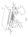
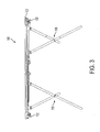
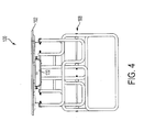
- Figures 1-4 depict an embodiment of the adjustable height desk platform 100 in a fully raised position
- Figures 5-6 depict the desk platform 100 in a fully lowered position
- the desk platform 100 can also be located in one or more intermediate positions between the fully raised and fully lowered positions.
- the desk platform 100 can include a platform 102 having an upper surface that defines a substantially flat work surface 104, and a lower surface 106 opposite to the work surface 104.
- the work surface 104 can occupy the entire upper surface of the platform 102.
- the work surface 104 can be substantially flat and devoid of any obstructions that would disrupt placing items on the work surface 104.
- other embodiments may include features (not shown) in the work surface 104, such as depressions or pockets to hold writing utensils or other items, or a raised edge to prevent items from rolling off the work surface 104.
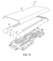
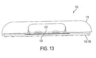
- the platform 102 can be constructed from a variety of materials, including plastic, composites, wood, particle board, cardboard, or other materials known in the art, or combinations thereof. As discussed in reference to Figures 12-16 below, the platform 102 can include additional component(s) to add to the aesthetics or increase the profile of the platform. Still referring to Figure 1 , the work surface 104 can define length L of between about 15 inches and about 36 inches, for example between about 20 inches and about 30 inches. The work surface 104 can also define a width W of between about 10 inches and about 20 inches, for example between about 12 inches and about 16 inches. One of ordinary skill in the art will appreciate from this disclosure, however, that other sizes and shapes of the work surface 104 are possible. For example, the work surface 104 can alternatively define a length L of between about 24 inches and about 60 inches, and a width W of between about 18 inches and about 36 inches.
- the desk platform 100 can include a first leg member 108 and a second leg member 110 coupled to the lower surface 106 of the platform 102.
- first leg member 108 and second leg member 110 When in the fully raised position, or any of the intermediate positions, the first leg member 108 and second leg member 110 together support the desk platform 100 above an existing surface, such as an office desk, sofa, or other surface.
- the first and second leg members 108, 110 can each be pivotably coupled to the platform 102 using brackets 112, or other structures known in the art.
- first and second leg member 108, 110 may each include two arm members and a horizontal member located between the two arm members.
- each of the first leg member 108 and the second leg member 110 can comprise two parts joined together.
- each of the first leg member 108 and the second leg member 110 can include a first leg component 114 coupled to the lower surface 106 of the platform 102, for example, using the brackets 112.
- Each leg member 108, 110 can also include a second leg component 116 pivotably coupled to the first leg component 114, for example, using screws, bolts, rivets, hinges, or other structures.
- first and second leg components 114, 116 each leg member 108, 110 can fold in an ergonomic and compact manner when moving between fully raised and fully lowered positions.
- first leg components 114 may each include a wide portion and a narrow portion, where the narrow portion is located between the arms of the respective second leg component 116.
- first and second leg components 114, 116 and the first and second leg members 108, 110 may be configured such that when they are in the fully lowered position, the first and second components 114, 116 and the first and second leg members 108, 110 are all positioned substantially horizontal to the work surface 104.
- leg members 108, 110 that are a single rigid component, or that comprise multiple components rigidly connected to one another.
- a portion of each second leg component 116 can be coupled to a rack and pinion gear system, to be described in more detail below.
- FIG. 7 and 8 an embodiment of a rack and pinion gear system 120 according to the present invention is shown.
- the rack and pinion gear system 120 can be used in conjunction with one or more latch mechanisms, described later, to releasably hold the leg members 108, 110 (only partially shown in Figures 7 and 8 ) in the fully raised position, fully lowered position, or in one or more intermediate positions therebetween.
- the rack and pinion gear system 120 can include a first rack gear 122 associated with the first leg member 108, and a second rack gear 124 associated with the second leg member 110.
- the first and second rack gears 122, 124 can be slidably mounted to the lower surface 106 of the platform 102, for example, using linear bearings 126 or other structures known in the art. Accordingly, the first rack gear 122 and second rack gear 124 can slide along the lower surface 106 substantially in parallel to one another, e.g., in and out of the paper as seen in Figure 8 .
- the first leg member 108 can be coupled to the first rack gear 122, for example, through its second leg component 116, such that moving the first leg member 108 between the fully raised and fully lowered positions causes the first rack gear 122 to slide along the lower surface 106 of the platform, e.g., within linear bearing 126.
- second leg member 110 can be coupled to the second rack gear 124, for example, through its second leg component 116, such that moving the first leg member 110 between the fully raised and fully lowered positions causes the second rack gear 124 to slide along the lower surface 106.
- simultaneously raising and lowering the first and second leg members 108, 110 can cause the first rack gear 122 and second rack gear 124 to move in substantially parallel, but opposite, directions.
- the rack and pinion gear system 120 can also include a pinion gear 130 located in contact with the first and second rack gears 122, 124.
- the pinion gear 130 can be rotatably mounted to the lower surface 106 of the platform 102 in between the movement paths of the first and second rack gears 122, 124. Due to their mutual engagement with the pinion gear 130, the first and second rack gears 122, 124 can be constrained to substantially proportional movement in substantially parallel, but opposite, directions. As a result, movement of the first leg member 108 and second leg member 110 can be synchronized.
- preventing rotation of the pinion gear 130 can immobilize the first and second rack gears 122, 124, and in turn, can substantially lock the position of the corresponding first and second leg members 108, 110 (e.g., in the fully raised position, fully lowered position, or an intermediate position there between).
- the desk platform 100 can also include a latch mechanism operable to engage and immobilize the pinion gear 130, or alternatively, to disengage the pinion gear 130.
- the latch mechanism can control whether the first and second members 108, 110 are locked in position, or are free to move with respect to the platform 102.
- Alternate embodiments can include a latch mechanism that engages some other part of the rack and pinion gear system 120, such as one or more of the rack gears 122, 124, or some other part associated therewith.
- the latch mechanism can include a handle 132 that is movable by a user, for example, pivotable with respect to the platform 102.
- the handle 132 can be connected to a latch member 134 (see Figures 2 and 7 ) adapted to engage the pinion gear 130.
- the handle 132 can be connected to the latch member 134 by a linkage member 136.
- Linkage member 136 can cause a portion of the latch member 134 to move in a horizontal direction and engage the pinion gear 130.
- the handle 132 can be pivotably mounted to the lower surface 106 of platform 102 by opposite pairs of pivot blocks 133, however, other configurations are possible.
- the latch member 134 can be biased into engagement with the pinion gear 130, such that the latch member 134 normally immobilizes the pinion gear 130. As a result, absent disengagement of the latch mechanism by the user, the latch mechanism will lock the rack and pinion gear system, 120, and substantially immobilize the first and second leg members 108, 110.
- springs or other elastic members associated with latch housing 138 can bias the latch member 134 into engagement with the pinion gear 130, however, other configurations are possible. For example, additionally or alternatively, springs or other elastic members associated with the handle 132 can bias the latch member 134 into engagement with the pinion gear 130.
- the desk platform 100 can include first and second latching mechanisms, both of which can be substantially as described above. Accordingly, the user may need to disengage both the first and second latch mechanisms in order to change the position of the first and second leg members 108, 110 with respect to the platform 102, however, other configurations are possible.
- one or more elastic members 140 may be provided to pre-load or bias the first and second leg members 108, 110 with respect to the platform 102.
- one of the elastic members 140 can be anchored to the second rack gear 124 at one end, and can be anchored to the lower surface 106 of the platform 102 at the opposite end.
- the elastic member 140 can be positioned such that moving the leg member 110 from the fully raised position toward the fully lowered position extends the elastic member 140, thereby providing resistance to movement in this lowering direction.
- FIG. 7 and 8 another elastic member 140 can also be provided in connection with the first leg member 108 and first rack gear 122. Recesses can be provided in the lower surface 106 of the platform 102 in the vicinity of the elastic members 140, e.g., to provide adequate clearance, however, other configurations are possible.
- the elastic members 140 are not limited to the configuration shown. Rather, other configurations are possible, as will be appreciated by one of ordinary skill in the art based on this disclosure.
- one or more standoffs 150 can be connected to the lower surface 106 of the platform 102 to maintain the first and/or second leg members 108, 110 in proper position with respect to the lower surface 106 when in the fully lowered position.
- the height of desk platform 100 can be adjusted by the user to suit his or her needs or environment.
- Figure 6 shows the desk platform in a fully lowered position.
- the user can disengage the latch mechanism from the rack and pinion gear system 120, thereby allowing the first and second leg members 108, 110 to raise with respect to the platform 102, for example, under the "lift assist" provided by optional elastic members 40.
- the user can then move the platform 102 to one of the intermediate positions, or to the fully raised position, and release the handle to re-engage the latch mechanism and rack and pinion gear system 120, thereby substantially locking the first and second leg members 108, 110 in place.
- Figure 1 shows the desk platform 100 in the fully raised position.
- the user can once again pivot the handles 132 to disengage the latch mechanism from the rack and pinion gear system 120 to move the platform 102 to the desired position.
- the user can move the platform 102 to the fully lowered position shown in Figure 6 to provide a compact configuration for storage, or for use while sitting. Movement of the platform 102 from the fully raised position toward the fully lowered position can extend the elastic members 140, thereby providing a dampening effect to the lowering motion.
- Figure 9 depicts a bottom, perspective, partially exploded view of another embodiment of the adjustable height desk platform 100.
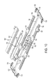
- Figure 10 depicts a partially exploded, perspective view of a portion of Figure 9 .
- the same reference numbers are used in Figures 9 and 10 to identify items that are the same as, or substantially similar to, features shown Figures 1-8 . Only significant differences between the embodiment of Figures 1-8 and the embodiment of Figures 9-10 are described below.
- the desk platform 100 can use tracks 160 to couple the first and second rack gears 122, 124 to the lower surface of the platform 102.
- each of the tracks 160 can be secured to the lower surface of the platform 102 using mounting brackets 162 that extend over the tracks 160, however, other configurations are possible.
- the tracks 160 can alternatively be screwed directly to the platform 102.
- one or more slide members 164 can connect each rack gear 122, 124 to the respective track 160.
- the tracks 160 can define an outer profile that compliments an inner profile of the slide members 164.
- the slide members 164 are retained on the tracks 160 in a manner that permits sliding of the sliding members 164 along the tracks 160.
- the rack gears 122, 124 can in turn be connected to the respective sliding members 164, for example, using fasteners, bonding, adhesives, or other structures.
- the second leg components 116 can couple to the respective rack gears 122, 124 using mounting tabs 168 on the rack gears 122, 124, and respective fasteners 166 located on the second leg components 116, however, other configurations are possible.
- embodiments of the desk platform 100 can include a carrying handle 170.
- the carrying handle 170 can be used by a user to facilitate transport of the desk platform.
- the handle 170 can mount to the lower surface of platform 102 using brackets 172.
- the handle can slide within brackets 172, allowing the handle 170 to move between a carrying position and a retracted position. Bent ends 173 or other retaining structures can prevent the handle 170 from disconnecting from the brackets 172 when in the carrying position.
- the entire handle 170 When in the retracted position, the entire handle 170 can be located behind the adjacent edge of the platform 102, such that none of the handle 170 protrudes laterally beyond the perimeter of the platform 102. In the extended position, a portion of the handle 170 can extend laterally beyond the perimeter of the platform 102, to provide a surface for the user to grip.
- recesses 174 can be provided in the lower surface 106 of the platform 102 in the vicinity of the tracks 160, or other components, to facilitate the desk platform 100 having a low profile.
- the desk platform 100 can include a cover 176 coupled to the lower surface of the platform 102.
- the cover 176 can extend over all or a substantial portion of the rack and pinion gear system, as well as the latch mechanism. Additionally or alternatively, the cover 176 can extend over the tracks 160 and associated components.
- the cover 176 can conceal many or all of the mechanical components of the deck platform 100 (e.g., all but the legs 108, 110 and other components that need to be exposed). This can add to the aesthetics and safety of the desk platform 100.
- brackets 180 can secure to the lower surface 106 of platform 102, as well as to the cover 176 (e.g., using screws or other fasteners) to attach cover 176 on the platform 102. Additionally or alternatively, other fasteners, adhesives, or known structures can be used to attach the cover 176 to the platform.
- the cover 176 may also be configured to be attached to a lower surface of the platform 102, where the lower surface of the platform 102 includes waffled ridges 175. These waffled ridges can help reduce the weight of the platform 102 while maintaining its structural integrity.
- the platform 102 can further comprise a cover 178 and a fitted work surface 105.
- the fitted work surface 105 can be configured to fit over a top surface of the cover 178.
- the fitted work surface 105 can snap onto the cover 178, for example, using detents, snaps, or other known structures, or alternatively, can be fastened to the cover 178 by fasteners, bonding, etc.
- the fitted work surface 105 can have a pair of rounded edges, which can add to the aesthetics of the desk platform 100.
- the cover 178 can include side cavities 179 to allow for movement of the handles 132.
- the cover 178 can also include holes through which screws or other fasteners may be inserted so that the brackets 112 may be attached to cover 178.
- the cover 178 can also include recesses to allow for movement of elastic members 140.
- first and second leg members 108,110 may be folded up beneath the platform 102. This allows for compact storage of the desk platform 100. As seen in Figure 15 , first and second leg members 108, 110 may be raised beneath the platform 102 for compact storage, as described in detail in regards to Figure 2 .
- Figure 16 shows an embodiment of an adjustable height desk platform, wherein the fitted work surface 105 may include aesthetic designs on an upper surface of the fitted work surface 105.
- fitted work surface 105 may also be formed of different colors and materials, based on an aesthetic choice.
- a variety of different work surfaces 105 can be provided with different aesthetic properties.
- the different work surfaces 105 may be interchangeably attachable to the cover 178 to vary the appearance of the desk platform 100.
Landscapes
- Tables And Desks Characterized By Structural Shape (AREA)
Applications Claiming Priority (1)
| Application Number | Priority Date | Filing Date | Title |
|---|---|---|---|
| US14/230,499 US9289058B2 (en) | 2014-03-31 | 2014-03-31 | Adjustable height desk platform |
Publications (2)
| Publication Number | Publication Date |
|---|---|
| EP2926689A1 true EP2926689A1 (fr) | 2015-10-07 |
| EP2926689B1 EP2926689B1 (fr) | 2019-02-27 |
Family
ID=52784955
Family Applications (1)
| Application Number | Title | Priority Date | Filing Date |
|---|---|---|---|
| EP15161122.5A Not-in-force EP2926689B1 (fr) | 2014-03-31 | 2015-03-26 | Plate-forme de bureau à hauteur réglable |
Country Status (8)
| Country | Link |
|---|---|
| US (1) | US9289058B2 (fr) |
| EP (1) | EP2926689B1 (fr) |
| JP (1) | JP2017513663A (fr) |
| KR (1) | KR20170028814A (fr) |
| CN (2) | CN205180731U (fr) |
| AU (1) | AU2015201469B2 (fr) |
| CA (1) | CA2885812C (fr) |
| WO (1) | WO2015153099A1 (fr) |
Cited By (2)
| Publication number | Priority date | Publication date | Assignee | Title |
|---|---|---|---|---|
| USD850172S1 (en) | 2017-05-08 | 2019-06-04 | Designa Inc. | Mobile height-adjustable work station |
| USD851852S1 (en) | 2017-05-08 | 2019-06-18 | Designa Inc. | Mobile height-adjustable work station |
Families Citing this family (33)
| Publication number | Priority date | Publication date | Assignee | Title |
|---|---|---|---|---|
| US9289058B2 (en) * | 2014-03-31 | 2016-03-22 | Varidesk, Llc | Adjustable height desk platform |
| USD785386S1 (en) | 2014-12-19 | 2017-05-02 | Varidesk, Llc | Desk |
| USD785989S1 (en) * | 2014-12-23 | 2017-05-09 | Varidesk, Llc | Desk |
| USD781618S1 (en) * | 2014-12-23 | 2017-03-21 | Varidesk, Llc | Desk |
| USD781617S1 (en) * | 2014-12-23 | 2017-03-21 | Varidesk, Llc | Desk |
| USD784050S1 (en) * | 2014-12-23 | 2017-04-18 | Varidesk, Llc | Desk |
| USD781619S1 (en) | 2014-12-23 | 2017-03-21 | Varidesk, Llc | Desk |
| USD785375S1 (en) | 2014-12-23 | 2017-05-02 | Varidesk, Llc | Desk |
| MX2017010085A (es) * | 2015-02-04 | 2017-11-23 | Affinity Tool Works Llc | Banco de trabajo movil plegable y soporte para herramienta. |
| CA2925376A1 (fr) | 2015-04-01 | 2016-10-01 | Timothy Hing-Yan Chung | Ensemble de dessus de table a hauteur reglable portable et methode d'ajustement de la hauteur dudit ensemble |
| USD804862S1 (en) * | 2015-05-13 | 2017-12-12 | Varidesk, Llc | Desk |
| USD814214S1 (en) | 2015-07-17 | 2018-04-03 | Varidesk, Llc | Desk |
| JP6751289B2 (ja) * | 2015-11-09 | 2020-09-02 | 株式会社オカムラ | 天板昇降式デスク |
| CN209565553U (zh) * | 2015-11-11 | 2019-11-01 | 史丹利工具(以色列)有限公司 | 工作台 |
| US10285496B2 (en) | 2016-06-03 | 2019-05-14 | Designa Inc. | Height adjustment mechanism and platform |
| CN105901923B (zh) | 2016-06-03 | 2017-10-24 | 佛山市迪赛纳科技有限公司 | 升降机构及包含升降机构的升降工作台和工作台升降方法 |
| USD841369S1 (en) | 2016-08-01 | 2019-02-26 | Designa Inc. | Height adjustment platform |
| AU2017254956B2 (en) * | 2016-09-08 | 2018-05-17 | Movi Workspace Pty Ltd | Desk mountable workstation |
| CN106239445A (zh) * | 2016-09-21 | 2016-12-21 | 宁波渠成进出口有限公司 | 可升降的工作台 |
| US10111518B2 (en) | 2016-11-23 | 2018-10-30 | Knape & Vogt Manufacturing Company | Adjustable ergonomic workstation |
| US10555603B2 (en) * | 2016-11-28 | 2020-02-11 | Lumi Legend Corporation | Height adjustable workstation |
| CN107041626B (zh) * | 2017-03-16 | 2020-02-28 | 韩桂云 | 一种可升降办公桌 |
| US10092089B1 (en) * | 2017-06-06 | 2018-10-09 | Chung Chiao Holding Corp. | Height-adjustable table |
| US10085550B1 (en) * | 2017-08-07 | 2018-10-02 | Chen-Source Inc. | Single lever-operated height-adjustable table |
| USD843137S1 (en) | 2017-08-21 | 2019-03-19 | Designa Inc. | Height adjustable workstation |
| CN109700183B (zh) * | 2019-01-31 | 2023-11-21 | 黄建明 | 一种摆放式升降台 |
| CN114667088A (zh) * | 2019-10-10 | 2022-06-24 | 科尔布鲁克博松及桑德斯(产品)有限公司 | 台式升降器 |
| CN111168652B (zh) * | 2020-01-19 | 2021-04-02 | 广东博智林机器人有限公司 | 折叠式支撑装置和机器人 |
| US11696638B2 (en) | 2020-05-13 | 2023-07-11 | Four Board Woodworks, LLC | Convertible table |
| US11109671B1 (en) * | 2020-06-04 | 2021-09-07 | C.D. Great Furniture Co., Ltd. | Height-adjustable table structure |
| CN114803052B (zh) * | 2022-05-24 | 2024-08-16 | 郑红燕 | 多功能收纳箱 |
| US20250234989A1 (en) * | 2024-01-19 | 2025-07-24 | A&C Future, Inc. | Foldable table |
| US12295489B1 (en) * | 2024-07-12 | 2025-05-13 | Marina Tf Pte. Ltd. | Powered lifting table |
Citations (4)
| Publication number | Priority date | Publication date | Assignee | Title |
|---|---|---|---|---|
| US165885A (en) * | 1875-07-20 | Improvement in accountants hand-rests | ||
| US2814541A (en) * | 1957-03-13 | 1957-11-26 | Derman Sam | Collapsible extensible table |
| US4662286A (en) * | 1986-01-13 | 1987-05-05 | Castro Convertible Corporation | Convertible table |
| CN101849736B (zh) * | 2010-06-17 | 2012-04-04 | 张勇 | 一种升降茶几的升降辅助装置 |
Family Cites Families (24)
| Publication number | Priority date | Publication date | Assignee | Title |
|---|---|---|---|---|
| US150220A (en) * | 1874-04-28 | Improvement in folding tables | ||
| US145858A (en) * | 1873-12-23 | Improvement in sewing-stands | ||
| US294954A (en) * | 1884-03-11 | John baggs | ||
| US831994A (en) * | 1905-11-28 | 1906-09-25 | Frank Rudman | Scaffold-machine. |
| US2664329A (en) * | 1949-08-13 | 1953-12-29 | Reinhold M Kraska | Table with folding legs |
| US2761743A (en) * | 1955-07-22 | 1956-09-04 | Cottar Robert | Adjustable scaffold leg unit |
| US2846282A (en) * | 1955-11-18 | 1958-08-05 | Jr Guy Barker | Table extendable in height and size |
| US2799546A (en) * | 1956-09-13 | 1957-07-16 | Michael J Lowry | Foldable, extensible table |
| US2818256A (en) * | 1956-10-31 | 1957-12-31 | Wilbert C Hopper | Game table |
| JPS49105401U (fr) * | 1972-12-28 | 1974-09-10 | ||
| JPS5537119Y2 (fr) * | 1977-10-24 | 1980-09-01 | ||
| US4747353A (en) * | 1986-10-14 | 1988-05-31 | Weber-Knapp Company | Straight line motion mechanism |
| JPH0517984Y2 (fr) * | 1989-07-24 | 1993-05-13 | ||
| US6752091B2 (en) * | 2001-01-12 | 2004-06-22 | Cosco Management, Inc. | Folding banquet table |
| US6912961B2 (en) * | 2002-01-09 | 2005-07-05 | Lifetime Products, Inc. | Personal table |
| CN2521968Y (zh) * | 2002-01-29 | 2002-11-27 | 吕孝兰 | 可升茶几 |
| JP3097252U (ja) * | 2003-04-17 | 2004-01-22 | 楊 信誠 | 高さが調整可能なテーブル |
| KR100601360B1 (ko) * | 2005-11-02 | 2006-07-19 | 희승산업주식회사 | 원터치 절첩식 책상다리를 구비한 책상 |
| DK176598B1 (da) * | 2006-02-10 | 2008-10-20 | Jesper Oestergaard Kristensen | Teleskop löftesöjle til höjdeindstilling af eleverbare borde |
| US8333271B2 (en) * | 2009-11-09 | 2012-12-18 | Gibson Brian D | Convertible luggage |
| CN103479104A (zh) * | 2012-06-13 | 2014-01-01 | 李绍汉 | 三节同步双缓冲抽屉导轨 |
| CN202739182U (zh) * | 2012-07-23 | 2013-02-20 | 吴建伟 | 一种可调节桌面高度的桌子 |
| TWM445388U (zh) * | 2012-08-07 | 2013-01-21 | Hui-Ling Huang | 具有輔助裝置之可調式桌具 |
| US9289058B2 (en) * | 2014-03-31 | 2016-03-22 | Varidesk, Llc | Adjustable height desk platform |
-
2014
- 2014-03-31 US US14/230,499 patent/US9289058B2/en not_active Expired - Fee Related
-
2015
- 2015-03-13 JP JP2017503769A patent/JP2017513663A/ja active Pending
- 2015-03-13 WO PCT/US2015/020392 patent/WO2015153099A1/fr not_active Ceased
- 2015-03-13 KR KR1020157021654A patent/KR20170028814A/ko not_active Withdrawn
- 2015-03-20 CA CA2885812A patent/CA2885812C/fr active Active
- 2015-03-20 AU AU2015201469A patent/AU2015201469B2/en not_active Ceased
- 2015-03-26 EP EP15161122.5A patent/EP2926689B1/fr not_active Not-in-force
- 2015-03-31 CN CN201520187646.5U patent/CN205180731U/zh not_active Expired - Fee Related
- 2015-03-31 CN CN201510146943.XA patent/CN105146910B/zh active Active
Patent Citations (4)
| Publication number | Priority date | Publication date | Assignee | Title |
|---|---|---|---|---|
| US165885A (en) * | 1875-07-20 | Improvement in accountants hand-rests | ||
| US2814541A (en) * | 1957-03-13 | 1957-11-26 | Derman Sam | Collapsible extensible table |
| US4662286A (en) * | 1986-01-13 | 1987-05-05 | Castro Convertible Corporation | Convertible table |
| CN101849736B (zh) * | 2010-06-17 | 2012-04-04 | 张勇 | 一种升降茶几的升降辅助装置 |
Cited By (2)
| Publication number | Priority date | Publication date | Assignee | Title |
|---|---|---|---|---|
| USD850172S1 (en) | 2017-05-08 | 2019-06-04 | Designa Inc. | Mobile height-adjustable work station |
| USD851852S1 (en) | 2017-05-08 | 2019-06-18 | Designa Inc. | Mobile height-adjustable work station |
Also Published As
| Publication number | Publication date |
|---|---|
| CN105146910A (zh) | 2015-12-16 |
| US20150272316A1 (en) | 2015-10-01 |
| KR20170028814A (ko) | 2017-03-14 |
| CA2885812A1 (fr) | 2015-09-30 |
| CN205180731U (zh) | 2016-04-27 |
| EP2926689B1 (fr) | 2019-02-27 |
| AU2015201469A1 (en) | 2015-10-15 |
| WO2015153099A1 (fr) | 2015-10-08 |
| AU2015201469B2 (en) | 2019-10-17 |
| US9289058B2 (en) | 2016-03-22 |
| JP2017513663A (ja) | 2017-06-01 |
| CN105146910B (zh) | 2018-09-21 |
| CA2885812C (fr) | 2023-02-07 |
Similar Documents
| Publication | Publication Date | Title |
|---|---|---|
| CA2885812C (fr) | Plateforme de bureau a hauteur reglable | |
| US10413053B2 (en) | Adjustable desk platform | |
| US5590607A (en) | Portable shelf for notebook computers | |
| US5816649A (en) | Chair with articulating tablet and interfacing table | |
| US10314750B2 (en) | Sliding arm mechanism for wheelchairs | |
| US8006327B1 (en) | Pivoting leg assembly for folding furniture | |
| EP2668872B1 (fr) | Chaise composite | |
| JP2011004917A (ja) | ワゴンデスク | |
| US20140158024A1 (en) | Table with privacy screen | |
| US8573688B2 (en) | Reconfigurable seating device with integral document shelf | |
| TWI613983B (zh) | 升降桌及其使用方法 | |
| US9980562B2 (en) | Tray table apparatus | |
| US8677910B2 (en) | Extendible table | |
| US5802988A (en) | Vertically adjustable table | |
| KR102695899B1 (ko) | 각도 조절 보조 책상 | |
| KR101726548B1 (ko) | 휠체어에 사용되는 너비 조절 가능한 책상 | |
| KR20160006086A (ko) | 접이탁자가 부착된 접이식 침대 | |
| US20150123431A1 (en) | Computing device tray for folding attachment to a chair | |
| TWI589252B (zh) | 躺椅裝置 | |
| KR20100005237U (ko) | 책상 | |
| GB2569531A (en) | Foot rest | |
| JP2008100030A (ja) | 車イス用テーブル | |
| AU2004202055A1 (en) | Multipurpose Tray | |
| JP2013102789A (ja) | 椅子 |
Legal Events
| Date | Code | Title | Description |
|---|---|---|---|
| PUAI | Public reference made under article 153(3) epc to a published international application that has entered the european phase |
Free format text: ORIGINAL CODE: 0009012 |
|
| 17P | Request for examination filed |
Effective date: 20150326 |
|
| AK | Designated contracting states |
Kind code of ref document: A1 Designated state(s): AL AT BE BG CH CY CZ DE DK EE ES FI FR GB GR HR HU IE IS IT LI LT LU LV MC MK MT NL NO PL PT RO RS SE SI SK SM TR |
|
| AX | Request for extension of the european patent |
Extension state: BA ME |
|
| RIN1 | Information on inventor provided before grant (corrected) |
Inventor name: FLAHERTY, DANIEL G. Inventor name: WANG, SHENG CHIEN Inventor name: PATTON, DAVID |
|
| 17Q | First examination report despatched |
Effective date: 20160801 |
|
| STAA | Information on the status of an ep patent application or granted ep patent |
Free format text: STATUS: EXAMINATION IS IN PROGRESS |
|
| RIC1 | Information provided on ipc code assigned before grant |
Ipc: A47B 3/02 20060101ALI20180509BHEP Ipc: A47B 3/08 20060101ALN20180509BHEP Ipc: A47B 9/16 20060101AFI20180509BHEP |
|
| GRAP | Despatch of communication of intention to grant a patent |
Free format text: ORIGINAL CODE: EPIDOSNIGR1 |
|
| STAA | Information on the status of an ep patent application or granted ep patent |
Free format text: STATUS: GRANT OF PATENT IS INTENDED |
|
| INTG | Intention to grant announced |
Effective date: 20180620 |
|
| GRAS | Grant fee paid |
Free format text: ORIGINAL CODE: EPIDOSNIGR3 |
|
| GRAJ | Information related to disapproval of communication of intention to grant by the applicant or resumption of examination proceedings by the epo deleted |
Free format text: ORIGINAL CODE: EPIDOSDIGR1 |
|
| GRAL | Information related to payment of fee for publishing/printing deleted |
Free format text: ORIGINAL CODE: EPIDOSDIGR3 |
|
| STAA | Information on the status of an ep patent application or granted ep patent |
Free format text: STATUS: EXAMINATION IS IN PROGRESS |
|
| GRAR | Information related to intention to grant a patent recorded |
Free format text: ORIGINAL CODE: EPIDOSNIGR71 |
|
| STAA | Information on the status of an ep patent application or granted ep patent |
Free format text: STATUS: GRANT OF PATENT IS INTENDED |
|
| GRAA | (expected) grant |
Free format text: ORIGINAL CODE: 0009210 |
|
| STAA | Information on the status of an ep patent application or granted ep patent |
Free format text: STATUS: THE PATENT HAS BEEN GRANTED |
|
| INTC | Intention to grant announced (deleted) | ||
| RIC1 | Information provided on ipc code assigned before grant |
Ipc: A47B 3/02 20060101ALI20190110BHEP Ipc: A47B 3/08 20060101ALN20190110BHEP Ipc: A47B 9/16 20060101AFI20190110BHEP |
|
| INTG | Intention to grant announced |
Effective date: 20190116 |
|
| AK | Designated contracting states |
Kind code of ref document: B1 Designated state(s): AL AT BE BG CH CY CZ DE DK EE ES FI FR GB GR HR HU IE IS IT LI LT LU LV MC MK MT NL NO PL PT RO RS SE SI SK SM TR |
|
| REG | Reference to a national code |
Ref country code: GB Ref legal event code: FG4D |
|
| REG | Reference to a national code |
Ref country code: CH Ref legal event code: EP |
|
| REG | Reference to a national code |
Ref country code: AT Ref legal event code: REF Ref document number: 1100115 Country of ref document: AT Kind code of ref document: T Effective date: 20190315 |
|
| REG | Reference to a national code |
Ref country code: IE Ref legal event code: FG4D |
|
| REG | Reference to a national code |
Ref country code: DE Ref legal event code: R096 Ref document number: 602015025194 Country of ref document: DE |
|
| REG | Reference to a national code |
Ref country code: NL Ref legal event code: FP |
|
| REG | Reference to a national code |
Ref country code: LT Ref legal event code: MG4D |
|
| PG25 | Lapsed in a contracting state [announced via postgrant information from national office to epo] |
Ref country code: LT Free format text: LAPSE BECAUSE OF FAILURE TO SUBMIT A TRANSLATION OF THE DESCRIPTION OR TO PAY THE FEE WITHIN THE PRESCRIBED TIME-LIMIT Effective date: 20190227 Ref country code: FI Free format text: LAPSE BECAUSE OF FAILURE TO SUBMIT A TRANSLATION OF THE DESCRIPTION OR TO PAY THE FEE WITHIN THE PRESCRIBED TIME-LIMIT Effective date: 20190227 Ref country code: SE Free format text: LAPSE BECAUSE OF FAILURE TO SUBMIT A TRANSLATION OF THE DESCRIPTION OR TO PAY THE FEE WITHIN THE PRESCRIBED TIME-LIMIT Effective date: 20190227 Ref country code: NO Free format text: LAPSE BECAUSE OF FAILURE TO SUBMIT A TRANSLATION OF THE DESCRIPTION OR TO PAY THE FEE WITHIN THE PRESCRIBED TIME-LIMIT Effective date: 20190527 Ref country code: PT Free format text: LAPSE BECAUSE OF FAILURE TO SUBMIT A TRANSLATION OF THE DESCRIPTION OR TO PAY THE FEE WITHIN THE PRESCRIBED TIME-LIMIT Effective date: 20190627 |
|
| PG25 | Lapsed in a contracting state [announced via postgrant information from national office to epo] |
Ref country code: GR Free format text: LAPSE BECAUSE OF FAILURE TO SUBMIT A TRANSLATION OF THE DESCRIPTION OR TO PAY THE FEE WITHIN THE PRESCRIBED TIME-LIMIT Effective date: 20190528 Ref country code: BG Free format text: LAPSE BECAUSE OF FAILURE TO SUBMIT A TRANSLATION OF THE DESCRIPTION OR TO PAY THE FEE WITHIN THE PRESCRIBED TIME-LIMIT Effective date: 20190527 Ref country code: RS Free format text: LAPSE BECAUSE OF FAILURE TO SUBMIT A TRANSLATION OF THE DESCRIPTION OR TO PAY THE FEE WITHIN THE PRESCRIBED TIME-LIMIT Effective date: 20190227 Ref country code: HR Free format text: LAPSE BECAUSE OF FAILURE TO SUBMIT A TRANSLATION OF THE DESCRIPTION OR TO PAY THE FEE WITHIN THE PRESCRIBED TIME-LIMIT Effective date: 20190227 Ref country code: IS Free format text: LAPSE BECAUSE OF FAILURE TO SUBMIT A TRANSLATION OF THE DESCRIPTION OR TO PAY THE FEE WITHIN THE PRESCRIBED TIME-LIMIT Effective date: 20190627 Ref country code: LV Free format text: LAPSE BECAUSE OF FAILURE TO SUBMIT A TRANSLATION OF THE DESCRIPTION OR TO PAY THE FEE WITHIN THE PRESCRIBED TIME-LIMIT Effective date: 20190227 |
|
| REG | Reference to a national code |
Ref country code: AT Ref legal event code: MK05 Ref document number: 1100115 Country of ref document: AT Kind code of ref document: T Effective date: 20190227 |
|
| PG25 | Lapsed in a contracting state [announced via postgrant information from national office to epo] |
Ref country code: AL Free format text: LAPSE BECAUSE OF FAILURE TO SUBMIT A TRANSLATION OF THE DESCRIPTION OR TO PAY THE FEE WITHIN THE PRESCRIBED TIME-LIMIT Effective date: 20190227 Ref country code: EE Free format text: LAPSE BECAUSE OF FAILURE TO SUBMIT A TRANSLATION OF THE DESCRIPTION OR TO PAY THE FEE WITHIN THE PRESCRIBED TIME-LIMIT Effective date: 20190227 Ref country code: DK Free format text: LAPSE BECAUSE OF FAILURE TO SUBMIT A TRANSLATION OF THE DESCRIPTION OR TO PAY THE FEE WITHIN THE PRESCRIBED TIME-LIMIT Effective date: 20190227 Ref country code: SK Free format text: LAPSE BECAUSE OF FAILURE TO SUBMIT A TRANSLATION OF THE DESCRIPTION OR TO PAY THE FEE WITHIN THE PRESCRIBED TIME-LIMIT Effective date: 20190227 Ref country code: RO Free format text: LAPSE BECAUSE OF FAILURE TO SUBMIT A TRANSLATION OF THE DESCRIPTION OR TO PAY THE FEE WITHIN THE PRESCRIBED TIME-LIMIT Effective date: 20190227 Ref country code: IT Free format text: LAPSE BECAUSE OF FAILURE TO SUBMIT A TRANSLATION OF THE DESCRIPTION OR TO PAY THE FEE WITHIN THE PRESCRIBED TIME-LIMIT Effective date: 20190227 Ref country code: CZ Free format text: LAPSE BECAUSE OF FAILURE TO SUBMIT A TRANSLATION OF THE DESCRIPTION OR TO PAY THE FEE WITHIN THE PRESCRIBED TIME-LIMIT Effective date: 20190227 Ref country code: ES Free format text: LAPSE BECAUSE OF FAILURE TO SUBMIT A TRANSLATION OF THE DESCRIPTION OR TO PAY THE FEE WITHIN THE PRESCRIBED TIME-LIMIT Effective date: 20190227 |
|
| REG | Reference to a national code |
Ref country code: CH Ref legal event code: PL |
|
| REG | Reference to a national code |
Ref country code: DE Ref legal event code: R097 Ref document number: 602015025194 Country of ref document: DE |
|
| PG25 | Lapsed in a contracting state [announced via postgrant information from national office to epo] |
Ref country code: SM Free format text: LAPSE BECAUSE OF FAILURE TO SUBMIT A TRANSLATION OF THE DESCRIPTION OR TO PAY THE FEE WITHIN THE PRESCRIBED TIME-LIMIT Effective date: 20190227 Ref country code: PL Free format text: LAPSE BECAUSE OF FAILURE TO SUBMIT A TRANSLATION OF THE DESCRIPTION OR TO PAY THE FEE WITHIN THE PRESCRIBED TIME-LIMIT Effective date: 20190227 Ref country code: LU Free format text: LAPSE BECAUSE OF NON-PAYMENT OF DUE FEES Effective date: 20190326 |
|
| REG | Reference to a national code |
Ref country code: BE Ref legal event code: MM Effective date: 20190331 |
|
| PG25 | Lapsed in a contracting state [announced via postgrant information from national office to epo] |
Ref country code: MC Free format text: LAPSE BECAUSE OF FAILURE TO SUBMIT A TRANSLATION OF THE DESCRIPTION OR TO PAY THE FEE WITHIN THE PRESCRIBED TIME-LIMIT Effective date: 20190227 Ref country code: AT Free format text: LAPSE BECAUSE OF FAILURE TO SUBMIT A TRANSLATION OF THE DESCRIPTION OR TO PAY THE FEE WITHIN THE PRESCRIBED TIME-LIMIT Effective date: 20190227 |
|
| PLBE | No opposition filed within time limit |
Free format text: ORIGINAL CODE: 0009261 |
|
| STAA | Information on the status of an ep patent application or granted ep patent |
Free format text: STATUS: NO OPPOSITION FILED WITHIN TIME LIMIT |
|
| PG25 | Lapsed in a contracting state [announced via postgrant information from national office to epo] |
Ref country code: IE Free format text: LAPSE BECAUSE OF NON-PAYMENT OF DUE FEES Effective date: 20190326 Ref country code: CH Free format text: LAPSE BECAUSE OF NON-PAYMENT OF DUE FEES Effective date: 20190331 Ref country code: LI Free format text: LAPSE BECAUSE OF NON-PAYMENT OF DUE FEES Effective date: 20190331 |
|
| 26N | No opposition filed |
Effective date: 20191128 |
|
| PG25 | Lapsed in a contracting state [announced via postgrant information from national office to epo] |
Ref country code: BE Free format text: LAPSE BECAUSE OF NON-PAYMENT OF DUE FEES Effective date: 20190331 Ref country code: FR Free format text: LAPSE BECAUSE OF NON-PAYMENT OF DUE FEES Effective date: 20190427 Ref country code: SI Free format text: LAPSE BECAUSE OF FAILURE TO SUBMIT A TRANSLATION OF THE DESCRIPTION OR TO PAY THE FEE WITHIN THE PRESCRIBED TIME-LIMIT Effective date: 20190227 |
|
| PG25 | Lapsed in a contracting state [announced via postgrant information from national office to epo] |
Ref country code: TR Free format text: LAPSE BECAUSE OF FAILURE TO SUBMIT A TRANSLATION OF THE DESCRIPTION OR TO PAY THE FEE WITHIN THE PRESCRIBED TIME-LIMIT Effective date: 20190227 |
|
| PG25 | Lapsed in a contracting state [announced via postgrant information from national office to epo] |
Ref country code: MT Free format text: LAPSE BECAUSE OF NON-PAYMENT OF DUE FEES Effective date: 20190326 |
|
| PG25 | Lapsed in a contracting state [announced via postgrant information from national office to epo] |
Ref country code: CY Free format text: LAPSE BECAUSE OF FAILURE TO SUBMIT A TRANSLATION OF THE DESCRIPTION OR TO PAY THE FEE WITHIN THE PRESCRIBED TIME-LIMIT Effective date: 20190227 |
|
| PG25 | Lapsed in a contracting state [announced via postgrant information from national office to epo] |
Ref country code: HU Free format text: LAPSE BECAUSE OF FAILURE TO SUBMIT A TRANSLATION OF THE DESCRIPTION OR TO PAY THE FEE WITHIN THE PRESCRIBED TIME-LIMIT; INVALID AB INITIO Effective date: 20150326 |
|
| PG25 | Lapsed in a contracting state [announced via postgrant information from national office to epo] |
Ref country code: MK Free format text: LAPSE BECAUSE OF FAILURE TO SUBMIT A TRANSLATION OF THE DESCRIPTION OR TO PAY THE FEE WITHIN THE PRESCRIBED TIME-LIMIT Effective date: 20190227 |
|
| PGFP | Annual fee paid to national office [announced via postgrant information from national office to epo] |
Ref country code: GB Payment date: 20230206 Year of fee payment: 9 Ref country code: DE Payment date: 20230302 Year of fee payment: 9 |
|
| PGFP | Annual fee paid to national office [announced via postgrant information from national office to epo] |
Ref country code: NL Payment date: 20230322 Year of fee payment: 9 |
|
| REG | Reference to a national code |
Ref country code: DE Ref legal event code: R119 Ref document number: 602015025194 Country of ref document: DE |
|
| REG | Reference to a national code |
Ref country code: NL Ref legal event code: MM Effective date: 20240401 |
|
| GBPC | Gb: european patent ceased through non-payment of renewal fee |
Effective date: 20240326 |
|
| PG25 | Lapsed in a contracting state [announced via postgrant information from national office to epo] |
Ref country code: NL Free format text: LAPSE BECAUSE OF NON-PAYMENT OF DUE FEES Effective date: 20240401 |
|
| PG25 | Lapsed in a contracting state [announced via postgrant information from national office to epo] |
Ref country code: NL Free format text: LAPSE BECAUSE OF NON-PAYMENT OF DUE FEES Effective date: 20240401 |
|
| PG25 | Lapsed in a contracting state [announced via postgrant information from national office to epo] |
Ref country code: DE Free format text: LAPSE BECAUSE OF NON-PAYMENT OF DUE FEES Effective date: 20241001 |
|
| PG25 | Lapsed in a contracting state [announced via postgrant information from national office to epo] |
Ref country code: GB Free format text: LAPSE BECAUSE OF NON-PAYMENT OF DUE FEES Effective date: 20240326 |
|
| PG25 | Lapsed in a contracting state [announced via postgrant information from national office to epo] |
Ref country code: GB Free format text: LAPSE BECAUSE OF NON-PAYMENT OF DUE FEES Effective date: 20240326 Ref country code: DE Free format text: LAPSE BECAUSE OF NON-PAYMENT OF DUE FEES Effective date: 20241001 |