EP2926865A1 - Herstellungsverfahren eines hermetisch verschlossenen gehäuses zum einkapseln einer implantierbaren vorrichtung, und entsprechendes gehäuse - Google Patents
Herstellungsverfahren eines hermetisch verschlossenen gehäuses zum einkapseln einer implantierbaren vorrichtung, und entsprechendes gehäuse Download PDFInfo
- Publication number
- EP2926865A1 EP2926865A1 EP15161124.1A EP15161124A EP2926865A1 EP 2926865 A1 EP2926865 A1 EP 2926865A1 EP 15161124 A EP15161124 A EP 15161124A EP 2926865 A1 EP2926865 A1 EP 2926865A1
- Authority
- EP
- European Patent Office
- Prior art keywords
- frame
- metal frame
- substrate
- seal
- hermetic seal
- Prior art date
- Legal status (The legal status is an assumption and is not a legal conclusion. Google has not performed a legal analysis and makes no representation as to the accuracy of the status listed.)
- Granted
Links
Images

Classifications
-
- A—HUMAN NECESSITIES
- A61—MEDICAL OR VETERINARY SCIENCE; HYGIENE
- A61N—ELECTROTHERAPY; MAGNETOTHERAPY; RADIATION THERAPY; ULTRASOUND THERAPY
- A61N1/00—Electrotherapy; Circuits therefor
- A61N1/18—Applying electric currents by contact electrodes
- A61N1/32—Applying electric currents by contact electrodes alternating or intermittent currents
- A61N1/36—Applying electric currents by contact electrodes alternating or intermittent currents for stimulation
- A61N1/372—Arrangements in connection with the implantation of stimulators
- A61N1/375—Constructional arrangements, e.g. casings
- A61N1/37512—Pacemakers
-
- A—HUMAN NECESSITIES
- A61—MEDICAL OR VETERINARY SCIENCE; HYGIENE
- A61N—ELECTROTHERAPY; MAGNETOTHERAPY; RADIATION THERAPY; ULTRASOUND THERAPY
- A61N1/00—Electrotherapy; Circuits therefor
- A61N1/18—Applying electric currents by contact electrodes
- A61N1/32—Applying electric currents by contact electrodes alternating or intermittent currents
- A61N1/36—Applying electric currents by contact electrodes alternating or intermittent currents for stimulation
- A61N1/372—Arrangements in connection with the implantation of stimulators
- A61N1/375—Constructional arrangements, e.g. casings
- A61N1/3752—Details of casing-lead connections
- A61N1/3754—Feedthroughs
-
- B—PERFORMING OPERATIONS; TRANSPORTING
- B23—MACHINE TOOLS; METAL-WORKING NOT OTHERWISE PROVIDED FOR
- B23K—SOLDERING OR UNSOLDERING; WELDING; CLADDING OR PLATING BY SOLDERING OR WELDING; CUTTING BY APPLYING HEAT LOCALLY, e.g. FLAME CUTTING; WORKING BY LASER BEAM
- B23K1/00—Soldering, e.g. brazing, or unsoldering
- B23K1/0008—Soldering, e.g. brazing, or unsoldering specially adapted for particular articles or work
-
- B—PERFORMING OPERATIONS; TRANSPORTING
- B23—MACHINE TOOLS; METAL-WORKING NOT OTHERWISE PROVIDED FOR
- B23K—SOLDERING OR UNSOLDERING; WELDING; CLADDING OR PLATING BY SOLDERING OR WELDING; CUTTING BY APPLYING HEAT LOCALLY, e.g. FLAME CUTTING; WORKING BY LASER BEAM
- B23K1/00—Soldering, e.g. brazing, or unsoldering
- B23K1/14—Soldering, e.g. brazing, or unsoldering specially adapted for soldering seams
- B23K1/18—Soldering, e.g. brazing, or unsoldering specially adapted for soldering seams circumferential seams, e.g. of shells
-
- B—PERFORMING OPERATIONS; TRANSPORTING
- B23—MACHINE TOOLS; METAL-WORKING NOT OTHERWISE PROVIDED FOR
- B23K—SOLDERING OR UNSOLDERING; WELDING; CLADDING OR PLATING BY SOLDERING OR WELDING; CUTTING BY APPLYING HEAT LOCALLY, e.g. FLAME CUTTING; WORKING BY LASER BEAM
- B23K1/00—Soldering, e.g. brazing, or unsoldering
- B23K1/19—Soldering, e.g. brazing, or unsoldering taking account of the properties of the materials to be soldered
-
- B—PERFORMING OPERATIONS; TRANSPORTING
- B23—MACHINE TOOLS; METAL-WORKING NOT OTHERWISE PROVIDED FOR
- B23K—SOLDERING OR UNSOLDERING; WELDING; CLADDING OR PLATING BY SOLDERING OR WELDING; CUTTING BY APPLYING HEAT LOCALLY, e.g. FLAME CUTTING; WORKING BY LASER BEAM
- B23K26/00—Working by laser beam, e.g. welding, cutting or boring
- B23K26/20—Bonding
- B23K26/21—Bonding by welding
- B23K26/24—Seam welding
- B23K26/28—Seam welding of curved planar seams
-
- B—PERFORMING OPERATIONS; TRANSPORTING
- B23—MACHINE TOOLS; METAL-WORKING NOT OTHERWISE PROVIDED FOR
- B23K—SOLDERING OR UNSOLDERING; WELDING; CLADDING OR PLATING BY SOLDERING OR WELDING; CUTTING BY APPLYING HEAT LOCALLY, e.g. FLAME CUTTING; WORKING BY LASER BEAM
- B23K26/00—Working by laser beam, e.g. welding, cutting or boring
- B23K26/20—Bonding
- B23K26/32—Bonding taking account of the properties of the material involved
-
- A—HUMAN NECESSITIES
- A61—MEDICAL OR VETERINARY SCIENCE; HYGIENE
- A61N—ELECTROTHERAPY; MAGNETOTHERAPY; RADIATION THERAPY; ULTRASOUND THERAPY
- A61N1/00—Electrotherapy; Circuits therefor
- A61N1/18—Applying electric currents by contact electrodes
- A61N1/32—Applying electric currents by contact electrodes alternating or intermittent currents
- A61N1/36—Applying electric currents by contact electrodes alternating or intermittent currents for stimulation
- A61N1/3605—Implantable neurostimulators for stimulating central or peripheral nerve system
-
- B—PERFORMING OPERATIONS; TRANSPORTING
- B23—MACHINE TOOLS; METAL-WORKING NOT OTHERWISE PROVIDED FOR
- B23K—SOLDERING OR UNSOLDERING; WELDING; CLADDING OR PLATING BY SOLDERING OR WELDING; CUTTING BY APPLYING HEAT LOCALLY, e.g. FLAME CUTTING; WORKING BY LASER BEAM
- B23K2103/00—Materials to be soldered, welded or cut
- B23K2103/08—Non-ferrous metals or alloys
- B23K2103/14—Titanium or alloys thereof
-
- B—PERFORMING OPERATIONS; TRANSPORTING
- B23—MACHINE TOOLS; METAL-WORKING NOT OTHERWISE PROVIDED FOR
- B23K—SOLDERING OR UNSOLDERING; WELDING; CLADDING OR PLATING BY SOLDERING OR WELDING; CUTTING BY APPLYING HEAT LOCALLY, e.g. FLAME CUTTING; WORKING BY LASER BEAM
- B23K2103/00—Materials to be soldered, welded or cut
- B23K2103/18—Dissimilar materials
-
- B—PERFORMING OPERATIONS; TRANSPORTING
- B23—MACHINE TOOLS; METAL-WORKING NOT OTHERWISE PROVIDED FOR
- B23K—SOLDERING OR UNSOLDERING; WELDING; CLADDING OR PLATING BY SOLDERING OR WELDING; CUTTING BY APPLYING HEAT LOCALLY, e.g. FLAME CUTTING; WORKING BY LASER BEAM
- B23K2103/00—Materials to be soldered, welded or cut
- B23K2103/50—Inorganic materials other than metals or composite materials
- B23K2103/52—Ceramics
Definitions
- the invention relates to a method for producing a hermetic housing particularly intended for the encapsulation of a device and more particularly of an implantable medical device.
- the invention also relates to such a hermetic housing.
- Implantable biomedical devices such as pacemakers, cardiac defibrillators, cardiac monitors, pumps, biomedical sensors or neurostimulation devices, consist of a battery and a set of electronic components encapsulated in a metal housing. (usually titanium) biocompatible.
- the casing ensuring the encapsulation of the various components of the device must be hermetic to avoid contact between the components and the tissues or biological fluids.
- the patent U.S. 5,750,926 to Schulman et al. describes a housing ensuring the encapsulation of the various components necessary for the proper functioning of a neurostimulator. It is obtained by attaching a metal cover to an insulating substrate. Two steps are necessary to ensure the hermeticity of the housing: the first step provides for the formation of a first hermetic seal between a metal frame and the insulating substrate, generally by brazing. The second step allows for a second seal hermetic between the metal frame and the metal cover by localized welding and in particular by laser welding.
- the object of the invention is to further reduce the thickness of the encapsulation casings, without compromising their mechanical strength, in particular to obtain mechanically flexible housings.
- Such thin and flexible housings can significantly improve the comfort of the patient and consider implantation in areas of the human body difficult to access conventional devices.
- implantable neurostimulators they allow implantation closer to the area to be stimulated electrically, which reduces the risks associated with the rupture of extension cables and electrode probes.
- the first hermetic seal is formed on a portion of the interface and the method comprises, before step c), an additional step of disposing a ceramic frame on the opposite the metal frame opposite said interface, so as to partially cover this face, the projection surface of said ceramic frame in a projection plane covering the projection surface of said first seal in the same projection plane.
- the first hermetic seal formed in step c) is a solder joint.
- a substrate may then be provided in which a recess is formed, the solder joint being at least partially integrated in said recess.
- a metal frame in which a recess is formed, the solder joint being at least partially integrated in said recess.
- the invention also relates to a method of encapsulation of a device consisting in implementing the method of producing a hermetic package according to the invention and mounting at least one component of said device to be encapsulated on the substrate, after the step c).
- the ceramic frame is located inside the cavity.
- the ceramic frame is located outside the cavity.
- the first hermetic seal is preferably a solder joint.
- said substrate and / or said metal frame advantageously comprises a recess in which at least part of said solder joint is integrated.
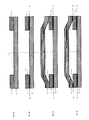
- the Figure 1A describes the first two steps of a method according to the state of the art, in which is provided a ceramic substrate 10, facing which is placed a metal frame 11.
- the Figure 1B illustrates a third step of the method in which a first hermetic seal 12 is formed at the interface between the metal frame 11 and the substrate 10, or between a lower face 110 of the metal frame and the substrate 10.
- This first hermetic seal 12 is formed by soldering and makes it possible to assemble the substrate and the frame.
- the figure 1C illustrates a fourth step in which a metal cover 13 is disposed on the metal frame 11.
- the figure 1D illustrates a fifth step of the process in which a second hermetic seal 14 is formed at the interface between the metal frame 11 and the cover 13, or between an upper face 111 of the frame 11 and the cover 13.
- This second seal 14 is formed by a welding process comprising a localized supply of heat, such as a laser beam welding.
- the brazing joint 12 Firstly, during the formation of the first hermetic seal 12 by brazing, chemical elements contained in the brazing joint 12 diffuse through the thickness of the metal frame 11, which results in an undesirable grip of the upper face 111. of the metal frame 11 on the sample holder. Indeed, the latter (not represented at figure 1 ) is used to apply pressure on the upper face 111 of the metal frame 11, during the formation of the first hermetic seal 12.
- the metal frame 11 is made of titanium and the first hermetic seal 12 consists of titanium and nickel
- the nickel diffuses through the thickness of the metal frame 11 and contributes to forming an undesirable grip zone between the upper face 111 of the metal frame 11 and the sample holder.
- the first hermetic seal 12 can be thermally degraded.
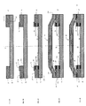
- FIG. 2 illustrates a method of manufacturing a hermetic package according to the invention.
- the Figure 2A illustrates the first two steps of the process which are identical to the first two steps of the method according to the state of the art.
- They consist in providing a ceramic substrate 20 and a metal frame 21 and putting it in front of the substrate 20.
- the ceramic substrate 20 may be of alumina, zirconia, zirconia stabilized with yttrium oxide, or zirconia stabilized with cerium oxide.
- the ceramic substrate 20 has an area of between 10 mm 2 and 100 cm 2 and a thickness of between 10 ⁇ m and 1 mm and, preferably, between 10 ⁇ m and 100 ⁇ m.
- the metal frame 21 may be titanium or titanium alloy.
- the metal frame 21 has a width of between 1 mm and 1 cm and a thickness of between 10 microns and 1 mm and preferably between 10 microns and 100 microns.
- the Figure 2B illustrates another step of the method in which is disposed a ceramic frame 25 on the upper face 211 of the frame 21, which face is opposed to the interface between the metal frame 25 and the substrate 20.
- this ceramic frame 25 covers only partially the upper face 211 of the frame 21.
- the frame 25 is located on the side of the inner face 213 of the metal frame 21.
- the inner edge 251 of the frame 25 is, in this example, located substantially vertically above the inside face 213 of the metal frame 21.
- the ceramic frame 25 may be of alumina, zirconia, zirconia stabilized with yttrium oxide or zirconia stabilized with cerium oxide.
- the ceramic frame 25 has a width of between 1 mm and 1 cm and a thickness of between 10 ⁇ m and 1 mm and, preferably, between 10 ⁇ m and 100 ⁇ m.
- the Figure 2C illustrates the following step in which is formed a first hermetic seal 22 at the interface between the substrate 20 and the frame metal 21, that is to say between the lower face 210 of the frame 21, opposite the upper face 211, and the substrate 20.
- This seal 22 is formed on a portion of the interface which is opposite the ceramic frame 25. This portion is therefore also located towards the inside of the housing in progress.
- the projection surface of the frame 25 in this projection plane is at least equal to the projection surface of the first hermetic seal 22 in the same plane of projection.
- the relative position of the frame 25 and the seal 22 is such that the projection surface of the frame 25 completely covers the projection surface of the seal 22.
- the seal 22 is formed on the entire interface.
- the surface area of the interface occupied by the seal 22 is between 20 and 80% to allow both an efficient assembly and the establishment of a cover.
- This first hermetic seal 22 may consist of titanium and nickel.
- a gripping zone 220 is simultaneously formed between the upper face 211 of the metal frame 21 and the ceramic frame 25. In fact, this results from the diffusion of the chemical elements contained in the seal brazing 22 through the thickness of the metal frame 21.
- the ceramic frame 25 for its part does not catch on the sample holder (not shown in FIG. figure 2 ) which is used to apply pressure on the ceramic frame 25, and thus indirectly on the upper face 211 of the metal frame 21, during the formation of the first hermetic seal 22.
- the nickel diffuses through the thickness of the metal frame 21 and contributes to forming the attachment zone 220 between the upper face 211 of the metal frame 21 and the ceramic frame 25.
- the nickel is only present at the first hermetic seal 22.
- the nickel is also found at the attachment zone 220, as well as throughout the part of the metal frame 21 between the first hermetic seal 22 and the attachment zone 220.
- first hermetic seal 22, attachment zone 220 and part of the metal frame 21 situated between the seal 22 and the attachment zone 220 have a similar chemical composition, these three zones containing titanium and nickel.
- the 2D figure illustrates the next step of the method in which a metal cover 23 is disposed on the upper face 211 of the metal frame 21.
- the outer edge 230 of the cover 23 is substantially in line with the outer face 212 of the metal frame 21 opposite face to the inner surface 213.
- the ceramic frame 25 is located inside the cavity 30 of the housing being formed.
- the metal cover 23 may be titanium or titanium alloy.
- the metal cover 23 has a thickness of between 10 microns and 1 mm, and preferably between 10 microns and 100 microns.
- a second hermetic seal 24 is formed between the upper face 211 of the metal frame 21 and the cover 23.
- This seal 24 is formed by a welding process performed with a localized supply of heat, such as a laser beam welding.
- the risk of thermally degrading the first hermetic seal 22 is very low, since the second hermetic seal 24 is offset laterally with respect to the first hermetic seal 22, the first seal 22 being located at the inside the cavity 30 and the second seal 24 at the periphery of the cavity.
- the two seals 22 and 24 are shifted both in a common projection plane, parallel to the substrate 20, and in another common projection plane, perpendicular to the substrate 20.
- the lateral offset between the two hermetic seals makes it possible to avoid any degradation of the first hermetic seal during the formation of the second seal.
- figure 3 illustrates an alternative embodiment of the method illustrated in FIG. figure 2 .
- this embodiment variant consists in arranging the ceramic frame 25 on the outside of the metal frame 21 so as to partially cover the upper face 211 of the frame 21.
- the outer edge 250 of the ceramic frame 25, opposite the inner edge 251 is located substantially vertically above the outer face 212 of the metal frame 21, opposite the inner face 213.
- first hermetic seal 22 at the interface between the metal frame 21 and the substrate 20 is carried out as described previously with regard to the Figure 2C and will not be described in more detail.
- This step makes it possible not only to obtain the hermetic seal 22 between the lower face 210 of the frame 21 and the substrate 20, but also a zone of attachment 220 between the upper face 211 of the frame 21 and the ceramic frame 25.
- the projection surface of the ceramic frame 25 in a projection plane is at least equal to the projection surface of the seal 22 in the same plane.
- This common projection plane may in particular comprise the seal 22 and correspond to the plane of the substrate 20.
- the relative position of the ceramic frame 25 and the seal 22 is such that the projection surface of the frame 25 completely covers the projection surface of the seal 22, in this common projection plane.
- the frame 25 avoids any attachment of a sample holder on the metal frame 21.
- the lid 33 is then superimposed on the assembly obtained.
- the figure 3B shows that, in this embodiment of the method, the outer edge 330 of the cover 33 is located towards the inside of the housing in progress with respect to the ceramic frame 25.
- the last step of the process consists in forming the second hermetic seal 24, as has been described with reference to the figure 2E .
- the figure 3B shows the case thus obtained.
- the ceramic frame 25 is here located outside the cavity 40 formed by the housing.
- This second variant embodiment of the process has the same advantages as those described with reference to the method described with reference to the figure 2 .
- the lateral offset between the two hermetic seals makes it possible to avoid any degradation of the first hermetic seal 22 during the formation of the second seal 24.
- first seal 22 is located outside the cavity 40 while the second seal is located at the periphery of this cavity.
- Another variant of the method according to the invention consists in making a recess in the ceramic substrate 20, in which recess is formed the solder joint 22, the seal being at least partially integrated in this recess.
- Another variant of the method consists in providing such a recess in the metal frame 21.
- this recess makes it possible to further reduce the thickness of the hermetic package obtained by the method according to the invention, since the brazing joint lies partly in the recess made in the substrate and / or the lid. Indeed, the impact of the thickness of the solder joint on the thickness of the housing is thus reduced.
Landscapes
- Engineering & Computer Science (AREA)
- Health & Medical Sciences (AREA)
- Mechanical Engineering (AREA)
- Optics & Photonics (AREA)
- Physics & Mathematics (AREA)
- Life Sciences & Earth Sciences (AREA)
- Biomedical Technology (AREA)
- General Health & Medical Sciences (AREA)
- Public Health (AREA)
- Veterinary Medicine (AREA)
- Radiology & Medical Imaging (AREA)
- Nuclear Medicine, Radiotherapy & Molecular Imaging (AREA)
- Animal Behavior & Ethology (AREA)
- Plasma & Fusion (AREA)
- Chemical & Material Sciences (AREA)
- Materials Engineering (AREA)
- Biophysics (AREA)
- Heart & Thoracic Surgery (AREA)
- Piezo-Electric Or Mechanical Vibrators, Or Delay Or Filter Circuits (AREA)
- Ceramic Products (AREA)
Applications Claiming Priority (1)
| Application Number | Priority Date | Filing Date | Title |
|---|---|---|---|
| FR1452790A FR3019375B1 (fr) | 2014-03-31 | 2014-03-31 | Procede de realisation d'un boitier hermetique destine a l'encapsulation d'un dispositif implantable et boitier correspondant |
Publications (2)
| Publication Number | Publication Date |
|---|---|
| EP2926865A1 true EP2926865A1 (de) | 2015-10-07 |
| EP2926865B1 EP2926865B1 (de) | 2017-08-09 |
Family
ID=50976888
Family Applications (1)
| Application Number | Title | Priority Date | Filing Date |
|---|---|---|---|
| EP15161124.1A Active EP2926865B1 (de) | 2014-03-31 | 2015-03-26 | Herstellungsverfahren eines hermetisch verschlossenen gehäuses zum einkapseln einer implantierbaren vorrichtung, und entsprechendes gehäuse |
Country Status (3)
| Country | Link |
|---|---|
| US (1) | US9387336B2 (de) |
| EP (1) | EP2926865B1 (de) |
| FR (1) | FR3019375B1 (de) |
Cited By (1)
| Publication number | Priority date | Publication date | Assignee | Title |
|---|---|---|---|---|
| FR3042308A1 (fr) * | 2015-10-13 | 2017-04-14 | Commissariat Energie Atomique | Boitier pour composants microelectroniques |
Families Citing this family (2)
| Publication number | Priority date | Publication date | Assignee | Title |
|---|---|---|---|---|
| KR101656723B1 (ko) * | 2015-06-30 | 2016-09-12 | 재단법인 오송첨단의료산업진흥재단 | 피드스루 제조방법 |
| CN108211118B (zh) * | 2017-12-23 | 2021-11-26 | 深圳先进技术研究院 | 植入式封装体及其制造方法和植入式医疗器件 |
Citations (7)
| Publication number | Priority date | Publication date | Assignee | Title |
|---|---|---|---|---|
| EP0266210A2 (de) * | 1986-10-29 | 1988-05-04 | Kabushiki Kaisha Toshiba | Elektronischer Apparat mit einem keramischen Substrat |
| US5750926A (en) | 1995-08-16 | 1998-05-12 | Alfred E. Mann Foundation For Scientific Research | Hermetically sealed electrical feedthrough for use with implantable electronic devices |
| EP1445798A1 (de) * | 2001-11-12 | 2004-08-11 | Sumitomo Special Metals Company Limited | Kapselung für elektronische teile, deckel dafür, material für den deckel und verfahren zur herstellung des deckelmaterials |
| WO2006097842A1 (en) * | 2005-03-17 | 2006-09-21 | Hymite A/S | Thin package for a micro component |
| WO2012015756A2 (en) * | 2010-07-29 | 2012-02-02 | Proteus Biomedical, Inc. | Hybrid housing for implantable medical device |
| WO2013099167A1 (ja) * | 2011-12-28 | 2013-07-04 | 日本特殊陶業株式会社 | セラミックパッケージ |
| WO2013137214A1 (ja) * | 2012-03-14 | 2013-09-19 | 日本特殊陶業株式会社 | セラミック基板およびその製造方法 |
-
2014
- 2014-03-31 FR FR1452790A patent/FR3019375B1/fr active Active
-
2015
- 2015-03-26 EP EP15161124.1A patent/EP2926865B1/de active Active
- 2015-03-31 US US14/674,489 patent/US9387336B2/en active Active
Patent Citations (8)
| Publication number | Priority date | Publication date | Assignee | Title |
|---|---|---|---|---|
| EP0266210A2 (de) * | 1986-10-29 | 1988-05-04 | Kabushiki Kaisha Toshiba | Elektronischer Apparat mit einem keramischen Substrat |
| US5750926A (en) | 1995-08-16 | 1998-05-12 | Alfred E. Mann Foundation For Scientific Research | Hermetically sealed electrical feedthrough for use with implantable electronic devices |
| EP1445798A1 (de) * | 2001-11-12 | 2004-08-11 | Sumitomo Special Metals Company Limited | Kapselung für elektronische teile, deckel dafür, material für den deckel und verfahren zur herstellung des deckelmaterials |
| WO2006097842A1 (en) * | 2005-03-17 | 2006-09-21 | Hymite A/S | Thin package for a micro component |
| WO2012015756A2 (en) * | 2010-07-29 | 2012-02-02 | Proteus Biomedical, Inc. | Hybrid housing for implantable medical device |
| WO2013099167A1 (ja) * | 2011-12-28 | 2013-07-04 | 日本特殊陶業株式会社 | セラミックパッケージ |
| WO2013137214A1 (ja) * | 2012-03-14 | 2013-09-19 | 日本特殊陶業株式会社 | セラミック基板およびその製造方法 |
| US20140196935A1 (en) * | 2012-03-14 | 2014-07-17 | Ngk Spark Plug Co., Ltd. | Ceramic substrate and process for producing same |
Cited By (3)
| Publication number | Priority date | Publication date | Assignee | Title |
|---|---|---|---|---|
| FR3042308A1 (fr) * | 2015-10-13 | 2017-04-14 | Commissariat Energie Atomique | Boitier pour composants microelectroniques |
| EP3157057A1 (de) * | 2015-10-13 | 2017-04-19 | Commissariat À L'Énergie Atomique Et Aux Énergies Alternatives | Gehäuse für mikroelektronische bauteile |
| US10446810B2 (en) | 2015-10-13 | 2019-10-15 | Commissariat A L'energie Atomique Et Aux Energies Alternatives | Case for microelectronic components |
Also Published As
| Publication number | Publication date |
|---|---|
| US20150273219A1 (en) | 2015-10-01 |
| FR3019375A1 (fr) | 2015-10-02 |
| EP2926865B1 (de) | 2017-08-09 |
| FR3019375B1 (fr) | 2016-05-06 |
| US9387336B2 (en) | 2016-07-12 |
Similar Documents
| Publication | Publication Date | Title |
|---|---|---|
| EP0641934B1 (de) | Herstellungsverfahren einer Mikropumpe | |
| JP4630338B2 (ja) | 気密封止用キャップ、電子部品収納用パッケージおよび気密封止用キャップの製造方法 | |
| EP2952471B1 (de) | Verkapselungsstruktur mit mehreren hohlräumen versehen mit zugangskanälen unterschiedlicher höhe | |
| EP2926865B1 (de) | Herstellungsverfahren eines hermetisch verschlossenen gehäuses zum einkapseln einer implantierbaren vorrichtung, und entsprechendes gehäuse | |
| EP3396705B1 (de) | Versiegelungsvorrichtung und verkapselungsverfahren für eine mikroelektronische komponente mit einer solchen versiegelungsvorrichtung | |
| EP2507825B1 (de) | Verfahren zur montage und abdichtung eines gehäuses | |
| EP2931363B1 (de) | Hermetisches gehäuse zur einkapselung einer implantierbaren medizinischen vorrichtung | |
| CN105209949A (zh) | 用于制造能密闭式密封地钎焊到壳体中的窗口元件的方法和按该方法制造的自由形状窗口元件 | |
| EP3468733B1 (de) | Bauplattform zur generativ herstellung mit einem plattenförmigen versteifungselement ausgestattet, das teilweise in der dicke hohlräume aufweist | |
| EP2436065B1 (de) | Verfahren zur herstellung einer einfüllöffnung in einer wand einer energiespeichervorrichtung | |
| FR3010648A1 (fr) | Procede de realisation d'un boitier hermetique destine a l'encapsulation d'un dispositif implantable et boitier correspondant. | |
| EP3068485A1 (de) | Durchführungsvorrichtung, insbesondere für ein medizinisches implantatsystem und herstellungsverfahren | |
| EP3501042A1 (de) | Verfahren zum verbinden von übergreifenden komponenten mit optimierter dichte | |
| EP3441734B1 (de) | Herstellungsverfahren einer detektionsvorrichtung mit zwei substraten, und eine solche detektionsvorrichtung | |
| EP3243593B1 (de) | Lötverfahren eines metallelements auf ein zirkonoxid-teil, und gelötete implantierbare vorrichtung | |
| EP1760041A2 (de) | Verkapselungsverfahren eines elektrischen oder elektronischen Bauelements durch einen verbesserten Bonddraht | |
| EP2778121B1 (de) | Einkapselungsverfahren einer Mikrovorrichtung durch anodisches Bonden | |
| EP1824779B1 (de) | Vorrichtung und verfahren zur hermetischen abdichtung eines hohlraums in einem elektronischen bauteil | |
| FR2702329A1 (fr) | Procédé de fermeture hermétique d'enceinte en particulier d'enceinte contenant des circuits microélectroniques, et enceinte ainsi obtenue. | |
| EP3109921B1 (de) | Herstellungsverfahren einer elektronischen vorrichtung | |
| WO2002037511A1 (fr) | Procede de fabrication d"une traversee etanche a condensateur integre et element ainsi obtenu | |
| FR2983845A1 (fr) | Procede de realisation d'une microstructure comportant deux substrats relies mecaniquement | |
| WO2005114721A1 (fr) | Procede et dispositif d'encapsulation, notamment pour dispositifs micromecaniques | |
| JP2006324374A (ja) | 透光窓付き蓋体とその製造方法 |
Legal Events
| Date | Code | Title | Description |
|---|---|---|---|
| PUAI | Public reference made under article 153(3) epc to a published international application that has entered the european phase |
Free format text: ORIGINAL CODE: 0009012 |
|
| AK | Designated contracting states |
Kind code of ref document: A1 Designated state(s): AL AT BE BG CH CY CZ DE DK EE ES FI FR GB GR HR HU IE IS IT LI LT LU LV MC MK MT NL NO PL PT RO RS SE SI SK SM TR |
|
| AX | Request for extension of the european patent |
Extension state: BA ME |
|
| 17P | Request for examination filed |
Effective date: 20160406 |
|
| RBV | Designated contracting states (corrected) |
Designated state(s): AL AT BE BG CH CY CZ DE DK EE ES FI FR GB GR HR HU IE IS IT LI LT LU LV MC MK MT NL NO PL PT RO RS SE SI SK SM TR |
|
| GRAP | Despatch of communication of intention to grant a patent |
Free format text: ORIGINAL CODE: EPIDOSNIGR1 |
|
| STAA | Information on the status of an ep patent application or granted ep patent |
Free format text: STATUS: GRANT OF PATENT IS INTENDED |
|
| RIC1 | Information provided on ipc code assigned before grant |
Ipc: H05K 5/00 20060101ALI20170209BHEP Ipc: A61N 1/375 20060101AFI20170209BHEP |
|
| INTG | Intention to grant announced |
Effective date: 20170301 |
|
| GRAS | Grant fee paid |
Free format text: ORIGINAL CODE: EPIDOSNIGR3 |
|
| GRAA | (expected) grant |
Free format text: ORIGINAL CODE: 0009210 |
|
| STAA | Information on the status of an ep patent application or granted ep patent |
Free format text: STATUS: THE PATENT HAS BEEN GRANTED |
|
| AK | Designated contracting states |
Kind code of ref document: B1 Designated state(s): AL AT BE BG CH CY CZ DE DK EE ES FI FR GB GR HR HU IE IS IT LI LT LU LV MC MK MT NL NO PL PT RO RS SE SI SK SM TR |
|
| REG | Reference to a national code |
Ref country code: GB Ref legal event code: FG4D Free format text: NOT ENGLISH |
|
| REG | Reference to a national code |
Ref country code: CH Ref legal event code: EP Ref country code: AT Ref legal event code: REF Ref document number: 916173 Country of ref document: AT Kind code of ref document: T Effective date: 20170815 |
|
| REG | Reference to a national code |
Ref country code: IE Ref legal event code: FG4D Free format text: LANGUAGE OF EP DOCUMENT: FRENCH |
|
| REG | Reference to a national code |
Ref country code: DE Ref legal event code: R096 Ref document number: 602015003938 Country of ref document: DE |
|
| REG | Reference to a national code |
Ref country code: NL Ref legal event code: MP Effective date: 20170809 |
|
| REG | Reference to a national code |
Ref country code: LT Ref legal event code: MG4D |
|
| REG | Reference to a national code |
Ref country code: AT Ref legal event code: MK05 Ref document number: 916173 Country of ref document: AT Kind code of ref document: T Effective date: 20170809 |
|
| PG25 | Lapsed in a contracting state [announced via postgrant information from national office to epo] |
Ref country code: NL Free format text: LAPSE BECAUSE OF FAILURE TO SUBMIT A TRANSLATION OF THE DESCRIPTION OR TO PAY THE FEE WITHIN THE PRESCRIBED TIME-LIMIT Effective date: 20170809 Ref country code: LT Free format text: LAPSE BECAUSE OF FAILURE TO SUBMIT A TRANSLATION OF THE DESCRIPTION OR TO PAY THE FEE WITHIN THE PRESCRIBED TIME-LIMIT Effective date: 20170809 Ref country code: AT Free format text: LAPSE BECAUSE OF FAILURE TO SUBMIT A TRANSLATION OF THE DESCRIPTION OR TO PAY THE FEE WITHIN THE PRESCRIBED TIME-LIMIT Effective date: 20170809 Ref country code: FI Free format text: LAPSE BECAUSE OF FAILURE TO SUBMIT A TRANSLATION OF THE DESCRIPTION OR TO PAY THE FEE WITHIN THE PRESCRIBED TIME-LIMIT Effective date: 20170809 Ref country code: SE Free format text: LAPSE BECAUSE OF FAILURE TO SUBMIT A TRANSLATION OF THE DESCRIPTION OR TO PAY THE FEE WITHIN THE PRESCRIBED TIME-LIMIT Effective date: 20170809 Ref country code: HR Free format text: LAPSE BECAUSE OF FAILURE TO SUBMIT A TRANSLATION OF THE DESCRIPTION OR TO PAY THE FEE WITHIN THE PRESCRIBED TIME-LIMIT Effective date: 20170809 Ref country code: NO Free format text: LAPSE BECAUSE OF FAILURE TO SUBMIT A TRANSLATION OF THE DESCRIPTION OR TO PAY THE FEE WITHIN THE PRESCRIBED TIME-LIMIT Effective date: 20171109 |
|
| PG25 | Lapsed in a contracting state [announced via postgrant information from national office to epo] |
Ref country code: LV Free format text: LAPSE BECAUSE OF FAILURE TO SUBMIT A TRANSLATION OF THE DESCRIPTION OR TO PAY THE FEE WITHIN THE PRESCRIBED TIME-LIMIT Effective date: 20170809 Ref country code: GR Free format text: LAPSE BECAUSE OF FAILURE TO SUBMIT A TRANSLATION OF THE DESCRIPTION OR TO PAY THE FEE WITHIN THE PRESCRIBED TIME-LIMIT Effective date: 20171110 Ref country code: RS Free format text: LAPSE BECAUSE OF FAILURE TO SUBMIT A TRANSLATION OF THE DESCRIPTION OR TO PAY THE FEE WITHIN THE PRESCRIBED TIME-LIMIT Effective date: 20170809 Ref country code: ES Free format text: LAPSE BECAUSE OF FAILURE TO SUBMIT A TRANSLATION OF THE DESCRIPTION OR TO PAY THE FEE WITHIN THE PRESCRIBED TIME-LIMIT Effective date: 20170809 Ref country code: PL Free format text: LAPSE BECAUSE OF FAILURE TO SUBMIT A TRANSLATION OF THE DESCRIPTION OR TO PAY THE FEE WITHIN THE PRESCRIBED TIME-LIMIT Effective date: 20170809 Ref country code: IS Free format text: LAPSE BECAUSE OF FAILURE TO SUBMIT A TRANSLATION OF THE DESCRIPTION OR TO PAY THE FEE WITHIN THE PRESCRIBED TIME-LIMIT Effective date: 20171209 Ref country code: BG Free format text: LAPSE BECAUSE OF FAILURE TO SUBMIT A TRANSLATION OF THE DESCRIPTION OR TO PAY THE FEE WITHIN THE PRESCRIBED TIME-LIMIT Effective date: 20171109 |
|
| REG | Reference to a national code |
Ref country code: FR Ref legal event code: PLFP Year of fee payment: 4 |
|
| PG25 | Lapsed in a contracting state [announced via postgrant information from national office to epo] |
Ref country code: RO Free format text: LAPSE BECAUSE OF FAILURE TO SUBMIT A TRANSLATION OF THE DESCRIPTION OR TO PAY THE FEE WITHIN THE PRESCRIBED TIME-LIMIT Effective date: 20170809 Ref country code: CZ Free format text: LAPSE BECAUSE OF FAILURE TO SUBMIT A TRANSLATION OF THE DESCRIPTION OR TO PAY THE FEE WITHIN THE PRESCRIBED TIME-LIMIT Effective date: 20170809 Ref country code: DK Free format text: LAPSE BECAUSE OF FAILURE TO SUBMIT A TRANSLATION OF THE DESCRIPTION OR TO PAY THE FEE WITHIN THE PRESCRIBED TIME-LIMIT Effective date: 20170809 |
|
| REG | Reference to a national code |
Ref country code: DE Ref legal event code: R097 Ref document number: 602015003938 Country of ref document: DE |
|
| PG25 | Lapsed in a contracting state [announced via postgrant information from national office to epo] |
Ref country code: EE Free format text: LAPSE BECAUSE OF FAILURE TO SUBMIT A TRANSLATION OF THE DESCRIPTION OR TO PAY THE FEE WITHIN THE PRESCRIBED TIME-LIMIT Effective date: 20170809 Ref country code: SK Free format text: LAPSE BECAUSE OF FAILURE TO SUBMIT A TRANSLATION OF THE DESCRIPTION OR TO PAY THE FEE WITHIN THE PRESCRIBED TIME-LIMIT Effective date: 20170809 Ref country code: SM Free format text: LAPSE BECAUSE OF FAILURE TO SUBMIT A TRANSLATION OF THE DESCRIPTION OR TO PAY THE FEE WITHIN THE PRESCRIBED TIME-LIMIT Effective date: 20170809 Ref country code: IT Free format text: LAPSE BECAUSE OF FAILURE TO SUBMIT A TRANSLATION OF THE DESCRIPTION OR TO PAY THE FEE WITHIN THE PRESCRIBED TIME-LIMIT Effective date: 20170809 |
|
| PLBE | No opposition filed within time limit |
Free format text: ORIGINAL CODE: 0009261 |
|
| STAA | Information on the status of an ep patent application or granted ep patent |
Free format text: STATUS: NO OPPOSITION FILED WITHIN TIME LIMIT |
|
| 26N | No opposition filed |
Effective date: 20180511 |
|
| PG25 | Lapsed in a contracting state [announced via postgrant information from national office to epo] |
Ref country code: SI Free format text: LAPSE BECAUSE OF FAILURE TO SUBMIT A TRANSLATION OF THE DESCRIPTION OR TO PAY THE FEE WITHIN THE PRESCRIBED TIME-LIMIT Effective date: 20170809 |
|
| PG25 | Lapsed in a contracting state [announced via postgrant information from national office to epo] |
Ref country code: MT Free format text: LAPSE BECAUSE OF FAILURE TO SUBMIT A TRANSLATION OF THE DESCRIPTION OR TO PAY THE FEE WITHIN THE PRESCRIBED TIME-LIMIT Effective date: 20170809 |
|
| REG | Reference to a national code |
Ref country code: CH Ref legal event code: PL |
|
| PG25 | Lapsed in a contracting state [announced via postgrant information from national office to epo] |
Ref country code: MC Free format text: LAPSE BECAUSE OF FAILURE TO SUBMIT A TRANSLATION OF THE DESCRIPTION OR TO PAY THE FEE WITHIN THE PRESCRIBED TIME-LIMIT Effective date: 20170809 |
|
| REG | Reference to a national code |
Ref country code: BE Ref legal event code: MM Effective date: 20180331 |
|
| REG | Reference to a national code |
Ref country code: IE Ref legal event code: MM4A |
|
| PG25 | Lapsed in a contracting state [announced via postgrant information from national office to epo] |
Ref country code: LU Free format text: LAPSE BECAUSE OF NON-PAYMENT OF DUE FEES Effective date: 20180326 |
|
| PG25 | Lapsed in a contracting state [announced via postgrant information from national office to epo] |
Ref country code: IE Free format text: LAPSE BECAUSE OF NON-PAYMENT OF DUE FEES Effective date: 20180326 |
|
| PG25 | Lapsed in a contracting state [announced via postgrant information from national office to epo] |
Ref country code: BE Free format text: LAPSE BECAUSE OF NON-PAYMENT OF DUE FEES Effective date: 20180331 Ref country code: LI Free format text: LAPSE BECAUSE OF NON-PAYMENT OF DUE FEES Effective date: 20180331 Ref country code: CH Free format text: LAPSE BECAUSE OF NON-PAYMENT OF DUE FEES Effective date: 20180331 |
|
| PG25 | Lapsed in a contracting state [announced via postgrant information from national office to epo] |
Ref country code: TR Free format text: LAPSE BECAUSE OF FAILURE TO SUBMIT A TRANSLATION OF THE DESCRIPTION OR TO PAY THE FEE WITHIN THE PRESCRIBED TIME-LIMIT Effective date: 20170809 |
|
| PG25 | Lapsed in a contracting state [announced via postgrant information from national office to epo] |
Ref country code: PT Free format text: LAPSE BECAUSE OF FAILURE TO SUBMIT A TRANSLATION OF THE DESCRIPTION OR TO PAY THE FEE WITHIN THE PRESCRIBED TIME-LIMIT Effective date: 20170809 |
|
| PG25 | Lapsed in a contracting state [announced via postgrant information from national office to epo] |
Ref country code: CY Free format text: LAPSE BECAUSE OF FAILURE TO SUBMIT A TRANSLATION OF THE DESCRIPTION OR TO PAY THE FEE WITHIN THE PRESCRIBED TIME-LIMIT Effective date: 20170809 Ref country code: HU Free format text: LAPSE BECAUSE OF FAILURE TO SUBMIT A TRANSLATION OF THE DESCRIPTION OR TO PAY THE FEE WITHIN THE PRESCRIBED TIME-LIMIT; INVALID AB INITIO Effective date: 20150326 Ref country code: MK Free format text: LAPSE BECAUSE OF NON-PAYMENT OF DUE FEES Effective date: 20170809 |
|
| PG25 | Lapsed in a contracting state [announced via postgrant information from national office to epo] |
Ref country code: AL Free format text: LAPSE BECAUSE OF FAILURE TO SUBMIT A TRANSLATION OF THE DESCRIPTION OR TO PAY THE FEE WITHIN THE PRESCRIBED TIME-LIMIT Effective date: 20170809 |
|
| PGFP | Annual fee paid to national office [announced via postgrant information from national office to epo] |
Ref country code: GB Payment date: 20260324 Year of fee payment: 12 |
|
| PGFP | Annual fee paid to national office [announced via postgrant information from national office to epo] |
Ref country code: DE Payment date: 20260320 Year of fee payment: 12 |
|
| PGFP | Annual fee paid to national office [announced via postgrant information from national office to epo] |
Ref country code: FR Payment date: 20260324 Year of fee payment: 12 |