EP2926932B1 - Schneideinsatz, schneidwerkzeug und verfahren zur herstellung eines schneidwerkstücks - Google Patents
Schneideinsatz, schneidwerkzeug und verfahren zur herstellung eines schneidwerkstücks Download PDFInfo
- Publication number
- EP2926932B1 EP2926932B1 EP13858960.1A EP13858960A EP2926932B1 EP 2926932 B1 EP2926932 B1 EP 2926932B1 EP 13858960 A EP13858960 A EP 13858960A EP 2926932 B1 EP2926932 B1 EP 2926932B1
- Authority
- EP
- European Patent Office
- Prior art keywords
- cutting edge
- straight cutting
- straight
- insert
- cutting
- Prior art date
- Legal status (The legal status is an assumption and is not a legal conclusion. Google has not performed a legal analysis and makes no representation as to the accuracy of the status listed.)
- Active
Links
Images








Classifications
-
- B—PERFORMING OPERATIONS; TRANSPORTING
- B23—MACHINE TOOLS; METAL-WORKING NOT OTHERWISE PROVIDED FOR
- B23C—MILLING
- B23C5/00—Milling-cutters
- B23C5/02—Milling-cutters characterised by the shape of the cutter
- B23C5/06—Face-milling cutters, i.e. having only or primarily a substantially flat cutting surface
-
- B—PERFORMING OPERATIONS; TRANSPORTING
- B23—MACHINE TOOLS; METAL-WORKING NOT OTHERWISE PROVIDED FOR
- B23C—MILLING
- B23C2200/00—Details of milling cutting inserts
- B23C2200/08—Rake or top surfaces
- B23C2200/085—Rake or top surfaces discontinuous
-
- B—PERFORMING OPERATIONS; TRANSPORTING
- B23—MACHINE TOOLS; METAL-WORKING NOT OTHERWISE PROVIDED FOR
- B23C—MILLING
- B23C2200/00—Details of milling cutting inserts
- B23C2200/12—Side or flank surfaces
- B23C2200/125—Side or flank surfaces discontinuous
-
- B—PERFORMING OPERATIONS; TRANSPORTING
- B23—MACHINE TOOLS; METAL-WORKING NOT OTHERWISE PROVIDED FOR
- B23C—MILLING
- B23C2200/00—Details of milling cutting inserts
- B23C2200/20—Top or side views of the cutting edge
- B23C2200/205—Discontinuous cutting edges
-
- B—PERFORMING OPERATIONS; TRANSPORTING
- B23—MACHINE TOOLS; METAL-WORKING NOT OTHERWISE PROVIDED FOR
- B23C—MILLING
- B23C2200/00—Details of milling cutting inserts
- B23C2200/28—Angles
-
- B—PERFORMING OPERATIONS; TRANSPORTING
- B23—MACHINE TOOLS; METAL-WORKING NOT OTHERWISE PROVIDED FOR
- B23C—MILLING
- B23C5/00—Milling-cutters
- B23C5/16—Milling-cutters characterised by physical features other than shape
- B23C5/20—Milling-cutters characterised by physical features other than shape with removable cutter bits or teeth or cutting inserts
-
- B—PERFORMING OPERATIONS; TRANSPORTING
- B23—MACHINE TOOLS; METAL-WORKING NOT OTHERWISE PROVIDED FOR
- B23C—MILLING
- B23C5/00—Milling-cutters
- B23C5/16—Milling-cutters characterised by physical features other than shape
- B23C5/20—Milling-cutters characterised by physical features other than shape with removable cutter bits or teeth or cutting inserts
- B23C5/202—Plate-like cutting inserts with special form
-
- Y—GENERAL TAGGING OF NEW TECHNOLOGICAL DEVELOPMENTS; GENERAL TAGGING OF CROSS-SECTIONAL TECHNOLOGIES SPANNING OVER SEVERAL SECTIONS OF THE IPC; TECHNICAL SUBJECTS COVERED BY FORMER USPC CROSS-REFERENCE ART COLLECTIONS [XRACs] AND DIGESTS
- Y10—TECHNICAL SUBJECTS COVERED BY FORMER USPC
- Y10T—TECHNICAL SUBJECTS COVERED BY FORMER US CLASSIFICATION
- Y10T407/00—Cutters, for shaping
- Y10T407/19—Rotary cutting tool
- Y10T407/1906—Rotary cutting tool including holder [i.e., head] having seat for inserted tool
- Y10T407/1934—Rotary cutting tool including holder [i.e., head] having seat for inserted tool with separate means to fasten tool to holder
- Y10T407/1936—Apertured tool
-
- Y—GENERAL TAGGING OF NEW TECHNOLOGICAL DEVELOPMENTS; GENERAL TAGGING OF CROSS-SECTIONAL TECHNOLOGIES SPANNING OVER SEVERAL SECTIONS OF THE IPC; TECHNICAL SUBJECTS COVERED BY FORMER USPC CROSS-REFERENCE ART COLLECTIONS [XRACs] AND DIGESTS
- Y10—TECHNICAL SUBJECTS COVERED BY FORMER USPC
- Y10T—TECHNICAL SUBJECTS COVERED BY FORMER US CLASSIFICATION
- Y10T407/00—Cutters, for shaping
- Y10T407/23—Cutters, for shaping including tool having plural alternatively usable cutting edges
-
- Y—GENERAL TAGGING OF NEW TECHNOLOGICAL DEVELOPMENTS; GENERAL TAGGING OF CROSS-SECTIONAL TECHNOLOGIES SPANNING OVER SEVERAL SECTIONS OF THE IPC; TECHNICAL SUBJECTS COVERED BY FORMER USPC CROSS-REFERENCE ART COLLECTIONS [XRACs] AND DIGESTS
- Y10—TECHNICAL SUBJECTS COVERED BY FORMER USPC
- Y10T—TECHNICAL SUBJECTS COVERED BY FORMER US CLASSIFICATION
- Y10T407/00—Cutters, for shaping
- Y10T407/23—Cutters, for shaping including tool having plural alternatively usable cutting edges
- Y10T407/235—Cutters, for shaping including tool having plural alternatively usable cutting edges with integral chip breaker, guide or deflector
-
- Y—GENERAL TAGGING OF NEW TECHNOLOGICAL DEVELOPMENTS; GENERAL TAGGING OF CROSS-SECTIONAL TECHNOLOGIES SPANNING OVER SEVERAL SECTIONS OF THE IPC; TECHNICAL SUBJECTS COVERED BY FORMER USPC CROSS-REFERENCE ART COLLECTIONS [XRACs] AND DIGESTS
- Y10—TECHNICAL SUBJECTS COVERED BY FORMER USPC
- Y10T—TECHNICAL SUBJECTS COVERED BY FORMER US CLASSIFICATION
- Y10T409/00—Gear cutting, milling, or planing
- Y10T409/30—Milling
- Y10T409/303752—Process
Definitions
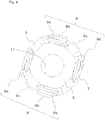
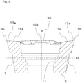
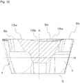
- the cutting insert 1 of the present embodiment has, as the rake surface 15 whose height from the lower surface 5 decreases as departing from the cutting edge 9, a first inclined surface 15a disposed along the first straight cutting edge 9b, a second inclined surface 15b disposed along the second straight cutting edge 9c, and a third inclined surface 15c disposed along the third straight cutting edge 9d.
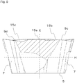
- the first straight cutting edge 9b is parallel to the lower surface 5, and the second straight cutting edge 9c and the third straight cutting edge 9d are inclined so as to have a smaller height from the lower surface 5 as departing from the first straight cutting edge 9b in the side view.
- the cutting edge 9 thus configured, it is possible to suppress cutting resistance even in the areas of the second straight cutting edge 9c and the third straight cutting edge 9d, both of which have the relatively large cutting edge angle, thereby increasing the chip thickness. It is also possible to make it easier for the chips generated by the cutting edge to be discharged in a direction away from the workpiece 201, thereby reducing the chip biting at the second straight cutting edge 9c and the third straight cutting edge 9d.
Landscapes
- Engineering & Computer Science (AREA)
- Mechanical Engineering (AREA)
- Milling Processes (AREA)
Claims (6)
- Ein Schneideinsatz (1), aufweisend:eine obere Fläche (3),eine untere Fläche (5),eine Seitenfläche (7), die mit jeder von der oberen Fläche (3) und der unteren Fläche (5) verbunden ist,eine Schneidkante (9), die in einer Draufsicht der Reihe nach aufweist: eine Eckschneidkante (9a), eine erste gerade Schneidkante (9b), eine zweite gerade Schneidkante (9c) und eine dritte gerade Schneidkante (9d), die entlang einem Schnittbereich der oberen Fläche (3) und der Seitenfläche (7) angeordnet sind und einander in einem stumpfen Winkel schneiden, undein Durchgangsloch (11), das sich von einem mittleren Teil der oberen Fläche (3) zu einem mittleren Teil der unteren Fläche (5) erstreckt,wobei die obere Fläche (3) aufweist: eine erste Neigungsfläche (15a), die sich entlang der ersten geraden Schneidkante (9b) erstreckt und in einer Schnittansicht von der ersten geraden Schneidkante (9b) in Richtung zu dem Durchgangsloch (11) von einer virtuellen Ebene (H) orthogonal zu einer zentralen Achse (X) des Durchgangslochs (11) eine geringere Höhe hat, während sie sich von der ersten geraden Schneidkante (9b) entfernt, eine zweite Neigungsfläche (15b), die sich entlang der zweiten geraden Schneidkante (9c) erstreckt und in einer Schnittansicht von der zweiten geraden Schneidkante (9c) in Richtung zu dem Durchgangsloch (11) von der virtuellen Ebene (H) aus eine geringere Höhe hat, während sie sich von der zweiten geraden Schneidkante (9c) entfernt, und eine dritte Neigungsfläche (15c), die sich entlang der dritten geraden Schneidkante (9d) erstreckt und in einer Schnittansicht von der dritten geraden Schneidkante (9d) in Richtung zu dem Durchgangsloch (11) von der virtuellen Ebene (H) aus eine geringere Höhe hat, während sie sich von der dritten geraden Schneidkante (9d) entfernt,dadurch gekennzeichnet, dass ein Neigungswinkel der zweiten Neigungsfläche (15b) relativ zu der virtuellen Ebene (H) größer als ein Neigungswinkel von jeder der ersten Neigungsfläche (15a) und der dritten Neigungsfläche (15c) relativ zu der virtuellen Ebene (H) ist.
- Der Schneideinsatz (1) gemäß Anspruch 1,wobei die obere Fläche (3) aufweist eine erste Stegfläche (13a), die sich zwischen der ersten geraden Schneidkante (9b) und der ersten Neigungsfläche (15a) befindet, eine zweite Stegfläche (13b), die sich zwischen der zweiten geraden Schneidkante (9c) und der zweiten Neigungsfläche (15b) befindet, und eine dritte Stegfläche (13c), die sich zwischen der dritten geraden Schneidkante (9d) und der dritten Neigungsfläche (15c) befindet, undwobei eine Breite zwischen der ersten geraden Schneidkante (9b) und der ersten Neigungsfläche (15a) auf der ersten Stegfläche (13a) größer als jede von einer Breite zwischen der zweiten geraden Schneidkante (9c) und der zweiten Neigungsfläche (15b) auf der zweiten Stegfläche (13b) und einer Breite zwischen der dritten geraden Schneidkante (9d) und der dritten Neigungsfläche (15c) auf der dritten Stegfläche (13c) ist.
- Der Schneideinsatz (1) gemäß Anspruch 1 oder 2, wobei die erste gerade Schneidkante (9b) parallel zu der unteren Fläche (5) ist und die zweite gerade Schneidkante (9c) und die dritte gerade Schneidkante (9d) geneigt sind, um von der virtuellen Ebene (H) aus in einer Seitenansicht eine geringere Höhe zu haben, während sie sich von der ersten geraden Schneidkante (9b) entfernen.
- Der Schneideinsatz (1) gemäß irgendeinem der Ansprüche 1 bis 3, wobei in einer Draufsicht eine Länge der zweiten geraden Schneidkante (9c) größer als eine Länge der dritten geraden Schneidkante (9d) ist und eine Länge der ersten geraden Schneidkante (9b) größer als die Länge der zweiten geraden Schneidkante (9c) ist.
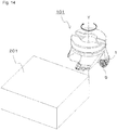
- Ein Schneidwerkzeug (101), aufweisend:eine Halterung (103), die eine Mehrzahl von Einsatztaschen (107) an einer vorderen Endseite eines Außenumfangs der Halterung (103) hat, undeinen Schneideinsatz (1) gemäß irgendeinem der Ansprüche 1 bis 4 zum Anbringen an den Einsatztaschen (107), so dass die Schneidkante (9) von der Halterung aus zur Seite hervorsteht.
- Ein Verfahren zum Herstellen eines maschinell bearbeiteten Produkts, aufweisend:Drehen eines Schneidwerkzeugs (101) gemäß Anspruch 5,in-Kontakt-Bringen der Schneidkante (9) des Schneidwerkzeugs (101), das gedreht wird, mit einem Werkstück (201), undTrennen des Schneidwerkzeugs (101) von dem Werkstück (201) .
Applications Claiming Priority (2)
| Application Number | Priority Date | Filing Date | Title |
|---|---|---|---|
| JP2012261818 | 2012-11-30 | ||
| PCT/JP2013/081890 WO2014084252A1 (ja) | 2012-11-30 | 2013-11-27 | 切削インサート、切削工具および切削加工物の製造方法 |
Publications (3)
| Publication Number | Publication Date |
|---|---|
| EP2926932A1 EP2926932A1 (de) | 2015-10-07 |
| EP2926932A4 EP2926932A4 (de) | 2016-04-20 |
| EP2926932B1 true EP2926932B1 (de) | 2019-01-16 |
Family
ID=50827884
Family Applications (1)
| Application Number | Title | Priority Date | Filing Date |
|---|---|---|---|
| EP13858960.1A Active EP2926932B1 (de) | 2012-11-30 | 2013-11-27 | Schneideinsatz, schneidwerkzeug und verfahren zur herstellung eines schneidwerkstücks |
Country Status (4)
| Country | Link |
|---|---|
| US (1) | US9718138B2 (de) |
| EP (1) | EP2926932B1 (de) |
| JP (1) | JP5905123B2 (de) |
| WO (1) | WO2014084252A1 (de) |
Families Citing this family (5)
| Publication number | Priority date | Publication date | Assignee | Title |
|---|---|---|---|---|
| KR102003446B1 (ko) * | 2018-01-19 | 2019-07-24 | 한국야금 주식회사 | 절삭 인서트 및 이를 장착한 절삭 공구 |
| JP1716025S (ja) * | 2021-10-25 | 2022-05-27 | 切削工具用インサート | |
| JP1716026S (ja) * | 2021-10-25 | 2022-05-27 | 切削工具用インサート | |
| JP1716024S (ja) * | 2021-10-25 | 2022-05-27 | 切削工具用インサート | |
| USD1029898S1 (en) * | 2022-04-21 | 2024-06-04 | Sumitomo Electric Hardmetal Corp. | Cutting tool insert |
Family Cites Families (16)
| Publication number | Priority date | Publication date | Assignee | Title |
|---|---|---|---|---|
| IL110785A (en) * | 1994-08-25 | 1998-04-05 | Iscar Ltd | Cutting insert for a rotary milling cutter |
| SE528016C2 (sv) * | 2004-05-14 | 2006-08-08 | Sandvik Intellectual Property | Svarvskär med en skarp övergång mellan en första och en andra egg |
| JP4810903B2 (ja) * | 2005-07-15 | 2011-11-09 | 株式会社タンガロイ | 転削工具および高送り用チップ |
| JP4449895B2 (ja) | 2005-12-19 | 2010-04-14 | 三菱マテリアル株式会社 | スローアウェイチップおよびスローアウェイ式切削工具 |
| KR100886455B1 (ko) * | 2006-12-27 | 2009-03-04 | 한국야금 주식회사 | 고능률 절삭 인서트 |
| SE531250C2 (sv) * | 2007-06-05 | 2009-02-03 | Sandvik Intellectual Property | Indexerbart hörnfrässkär |
| US8985915B2 (en) * | 2009-05-28 | 2015-03-24 | Kyocera Corporation | Cutting insert, cutting tool, and method of manufacturing machined product using the same |
| CN102427904B (zh) * | 2009-06-26 | 2013-10-16 | 京瓷株式会社 | 切削镶刀及切削工具、以及使用该切削工具的切削加工物的制造方法 |
| EP2450139B1 (de) * | 2009-06-29 | 2019-03-27 | Kyocera Corporation | Schneideeinsatz, schneidewerkzeug sowie herstellungsverfahren für schneideprodukte damit |
| WO2011024595A1 (ja) * | 2009-08-31 | 2011-03-03 | 京セラ株式会社 | 切削工具およびそれを用いた切削加工物の製造方法 |
| JP2013006221A (ja) * | 2009-10-13 | 2013-01-10 | Mitsubishi Materials Corp | 切削インサート及び刃先交換式回転工具 |
| CN102548694B (zh) * | 2009-10-28 | 2014-05-21 | 京瓷株式会社 | 切削镶刀及切削工具、以及使用该切削工具的切削加工物的制造方法 |
| JP5441615B2 (ja) * | 2009-10-29 | 2014-03-12 | 京セラ株式会社 | 切削インサートおよび切削工具ならびに被削加工物の製造方法 |
| CN102481641B (zh) * | 2010-01-29 | 2013-11-06 | 京瓷株式会社 | 切削镶刀及切削工具、以及使用该切削工具的切削加工物的制造方法 |
| EP2567768A1 (de) * | 2010-05-06 | 2013-03-13 | Tungaloy Corporation | Schneideeinsatz und schneidewerkzeug mit klingenspitzen-ersatzmöglichkeit |
| JP6205726B2 (ja) * | 2013-01-15 | 2017-10-04 | 三菱マテリアル株式会社 | 正面フライス用切削インサート及び刃先交換式正面フライス |
-
2013
- 2013-11-27 EP EP13858960.1A patent/EP2926932B1/de active Active
- 2013-11-27 WO PCT/JP2013/081890 patent/WO2014084252A1/ja not_active Ceased
- 2013-11-27 JP JP2014549859A patent/JP5905123B2/ja active Active
- 2013-11-27 US US14/646,096 patent/US9718138B2/en active Active
Non-Patent Citations (1)
| Title |
|---|
| None * |
Also Published As
| Publication number | Publication date |
|---|---|
| US20150336186A1 (en) | 2015-11-26 |
| EP2926932A4 (de) | 2016-04-20 |
| US9718138B2 (en) | 2017-08-01 |
| WO2014084252A1 (ja) | 2014-06-05 |
| EP2926932A1 (de) | 2015-10-07 |
| JPWO2014084252A1 (ja) | 2017-01-05 |
| JP5905123B2 (ja) | 2016-04-20 |
Similar Documents
| Publication | Publication Date | Title |
|---|---|---|
| US10058938B2 (en) | Cutting insert, cutting tool, and method of producing machined product | |
| EP2926933B1 (de) | Schneideinsatz, schneidwerkzeug und verfahren zur herstellung eines schneidwerkstücks | |
| US10213849B2 (en) | Cutting insert, cutting tool, and method of manufacturing a machined product | |
| EP3072617B1 (de) | Schneideinsatz, schneidwerkzeug sowie verfahren zur herstellung eines zerschnittenen artikels | |
| JP6337112B2 (ja) | 切削インサート、切削工具及び切削加工物の製造方法 | |
| EP3015205B1 (de) | Schneideinsatz, schneidwerkzeug und herstellungsverfahren für geschnittenes werkstück | |
| US10239125B2 (en) | Cutting insert, cutting tool, and method for manufacturing machined product using same | |
| EP2926932A1 (de) | Schneideeinsatz, schneidwerkzeug und schneidwerkstückherstellungsverfahren | |
| US10406610B2 (en) | Cutting insert, cutting tool, and method of manufacturing machined product | |
| US11517965B2 (en) | Cutting insert, cutting tool, and method of manufacturing machined product | |
| JP5952073B2 (ja) | 切削インサート、切削工具および被削加工物の製造方法 | |
| JP5762020B2 (ja) | 切削インサートおよび切削工具ならびにそれを用いた被削材の切削方法 | |
| JP6825854B2 (ja) | 切削工具及び切削加工物の製造方法 | |
| JPWO2018180780A1 (ja) | 切削インサート、ドリル及び切削加工物の製造方法 | |
| WO2024224768A1 (ja) | ドリルおよび切削加工物の製造方法 |
Legal Events
| Date | Code | Title | Description |
|---|---|---|---|
| PUAI | Public reference made under article 153(3) epc to a published international application that has entered the european phase |
Free format text: ORIGINAL CODE: 0009012 |
|
| 17P | Request for examination filed |
Effective date: 20150520 |
|
| AK | Designated contracting states |
Kind code of ref document: A1 Designated state(s): AL AT BE BG CH CY CZ DE DK EE ES FI FR GB GR HR HU IE IS IT LI LT LU LV MC MK MT NL NO PL PT RO RS SE SI SK SM TR |
|
| AX | Request for extension of the european patent |
Extension state: BA ME |
|
| DAX | Request for extension of the european patent (deleted) | ||
| RA4 | Supplementary search report drawn up and despatched (corrected) |
Effective date: 20160318 |
|
| RIC1 | Information provided on ipc code assigned before grant |
Ipc: B23C 5/20 20060101AFI20160314BHEP Ipc: B23C 5/06 20060101ALI20160314BHEP |
|
| GRAP | Despatch of communication of intention to grant a patent |
Free format text: ORIGINAL CODE: EPIDOSNIGR1 |
|
| STAA | Information on the status of an ep patent application or granted ep patent |
Free format text: STATUS: GRANT OF PATENT IS INTENDED |
|
| INTG | Intention to grant announced |
Effective date: 20180809 |
|
| RIN1 | Information on inventor provided before grant (corrected) |
Inventor name: ISHI, HIROHISA |
|
| GRAS | Grant fee paid |
Free format text: ORIGINAL CODE: EPIDOSNIGR3 |
|
| GRAA | (expected) grant |
Free format text: ORIGINAL CODE: 0009210 |
|
| STAA | Information on the status of an ep patent application or granted ep patent |
Free format text: STATUS: THE PATENT HAS BEEN GRANTED |
|
| AK | Designated contracting states |
Kind code of ref document: B1 Designated state(s): AL AT BE BG CH CY CZ DE DK EE ES FI FR GB GR HR HU IE IS IT LI LT LU LV MC MK MT NL NO PL PT RO RS SE SI SK SM TR |
|
| REG | Reference to a national code |
Ref country code: GB Ref legal event code: FG4D |
|
| REG | Reference to a national code |
Ref country code: CH Ref legal event code: EP |
|
| REG | Reference to a national code |
Ref country code: IE Ref legal event code: FG4D |
|
| REG | Reference to a national code |
Ref country code: DE Ref legal event code: R096 Ref document number: 602013050050 Country of ref document: DE |
|
| REG | Reference to a national code |
Ref country code: AT Ref legal event code: REF Ref document number: 1089340 Country of ref document: AT Kind code of ref document: T Effective date: 20190215 |
|
| REG | Reference to a national code |
Ref country code: NL Ref legal event code: MP Effective date: 20190116 |
|
| REG | Reference to a national code |
Ref country code: LT Ref legal event code: MG4D |
|
| PG25 | Lapsed in a contracting state [announced via postgrant information from national office to epo] |
Ref country code: NL Free format text: LAPSE BECAUSE OF FAILURE TO SUBMIT A TRANSLATION OF THE DESCRIPTION OR TO PAY THE FEE WITHIN THE PRESCRIBED TIME-LIMIT Effective date: 20190116 |
|
| REG | Reference to a national code |
Ref country code: AT Ref legal event code: MK05 Ref document number: 1089340 Country of ref document: AT Kind code of ref document: T Effective date: 20190116 |
|
| PG25 | Lapsed in a contracting state [announced via postgrant information from national office to epo] |
Ref country code: LT Free format text: LAPSE BECAUSE OF FAILURE TO SUBMIT A TRANSLATION OF THE DESCRIPTION OR TO PAY THE FEE WITHIN THE PRESCRIBED TIME-LIMIT Effective date: 20190116 Ref country code: FI Free format text: LAPSE BECAUSE OF FAILURE TO SUBMIT A TRANSLATION OF THE DESCRIPTION OR TO PAY THE FEE WITHIN THE PRESCRIBED TIME-LIMIT Effective date: 20190116 Ref country code: NO Free format text: LAPSE BECAUSE OF FAILURE TO SUBMIT A TRANSLATION OF THE DESCRIPTION OR TO PAY THE FEE WITHIN THE PRESCRIBED TIME-LIMIT Effective date: 20190416 Ref country code: SE Free format text: LAPSE BECAUSE OF FAILURE TO SUBMIT A TRANSLATION OF THE DESCRIPTION OR TO PAY THE FEE WITHIN THE PRESCRIBED TIME-LIMIT Effective date: 20190116 Ref country code: PL Free format text: LAPSE BECAUSE OF FAILURE TO SUBMIT A TRANSLATION OF THE DESCRIPTION OR TO PAY THE FEE WITHIN THE PRESCRIBED TIME-LIMIT Effective date: 20190116 Ref country code: ES Free format text: LAPSE BECAUSE OF FAILURE TO SUBMIT A TRANSLATION OF THE DESCRIPTION OR TO PAY THE FEE WITHIN THE PRESCRIBED TIME-LIMIT Effective date: 20190116 Ref country code: PT Free format text: LAPSE BECAUSE OF FAILURE TO SUBMIT A TRANSLATION OF THE DESCRIPTION OR TO PAY THE FEE WITHIN THE PRESCRIBED TIME-LIMIT Effective date: 20190516 |
|
| PG25 | Lapsed in a contracting state [announced via postgrant information from national office to epo] |
Ref country code: LV Free format text: LAPSE BECAUSE OF FAILURE TO SUBMIT A TRANSLATION OF THE DESCRIPTION OR TO PAY THE FEE WITHIN THE PRESCRIBED TIME-LIMIT Effective date: 20190116 Ref country code: RS Free format text: LAPSE BECAUSE OF FAILURE TO SUBMIT A TRANSLATION OF THE DESCRIPTION OR TO PAY THE FEE WITHIN THE PRESCRIBED TIME-LIMIT Effective date: 20190116 Ref country code: GR Free format text: LAPSE BECAUSE OF FAILURE TO SUBMIT A TRANSLATION OF THE DESCRIPTION OR TO PAY THE FEE WITHIN THE PRESCRIBED TIME-LIMIT Effective date: 20190417 Ref country code: BG Free format text: LAPSE BECAUSE OF FAILURE TO SUBMIT A TRANSLATION OF THE DESCRIPTION OR TO PAY THE FEE WITHIN THE PRESCRIBED TIME-LIMIT Effective date: 20190416 Ref country code: IS Free format text: LAPSE BECAUSE OF FAILURE TO SUBMIT A TRANSLATION OF THE DESCRIPTION OR TO PAY THE FEE WITHIN THE PRESCRIBED TIME-LIMIT Effective date: 20190516 Ref country code: HR Free format text: LAPSE BECAUSE OF FAILURE TO SUBMIT A TRANSLATION OF THE DESCRIPTION OR TO PAY THE FEE WITHIN THE PRESCRIBED TIME-LIMIT Effective date: 20190116 |
|
| REG | Reference to a national code |
Ref country code: DE Ref legal event code: R097 Ref document number: 602013050050 Country of ref document: DE |
|
| PG25 | Lapsed in a contracting state [announced via postgrant information from national office to epo] |
Ref country code: DK Free format text: LAPSE BECAUSE OF FAILURE TO SUBMIT A TRANSLATION OF THE DESCRIPTION OR TO PAY THE FEE WITHIN THE PRESCRIBED TIME-LIMIT Effective date: 20190116 Ref country code: AT Free format text: LAPSE BECAUSE OF FAILURE TO SUBMIT A TRANSLATION OF THE DESCRIPTION OR TO PAY THE FEE WITHIN THE PRESCRIBED TIME-LIMIT Effective date: 20190116 Ref country code: AL Free format text: LAPSE BECAUSE OF FAILURE TO SUBMIT A TRANSLATION OF THE DESCRIPTION OR TO PAY THE FEE WITHIN THE PRESCRIBED TIME-LIMIT Effective date: 20190116 Ref country code: SK Free format text: LAPSE BECAUSE OF FAILURE TO SUBMIT A TRANSLATION OF THE DESCRIPTION OR TO PAY THE FEE WITHIN THE PRESCRIBED TIME-LIMIT Effective date: 20190116 Ref country code: IT Free format text: LAPSE BECAUSE OF FAILURE TO SUBMIT A TRANSLATION OF THE DESCRIPTION OR TO PAY THE FEE WITHIN THE PRESCRIBED TIME-LIMIT Effective date: 20190116 Ref country code: EE Free format text: LAPSE BECAUSE OF FAILURE TO SUBMIT A TRANSLATION OF THE DESCRIPTION OR TO PAY THE FEE WITHIN THE PRESCRIBED TIME-LIMIT Effective date: 20190116 Ref country code: CZ Free format text: LAPSE BECAUSE OF FAILURE TO SUBMIT A TRANSLATION OF THE DESCRIPTION OR TO PAY THE FEE WITHIN THE PRESCRIBED TIME-LIMIT Effective date: 20190116 Ref country code: RO Free format text: LAPSE BECAUSE OF FAILURE TO SUBMIT A TRANSLATION OF THE DESCRIPTION OR TO PAY THE FEE WITHIN THE PRESCRIBED TIME-LIMIT Effective date: 20190116 |
|
| PLBE | No opposition filed within time limit |
Free format text: ORIGINAL CODE: 0009261 |
|
| STAA | Information on the status of an ep patent application or granted ep patent |
Free format text: STATUS: NO OPPOSITION FILED WITHIN TIME LIMIT |
|
| PG25 | Lapsed in a contracting state [announced via postgrant information from national office to epo] |
Ref country code: SM Free format text: LAPSE BECAUSE OF FAILURE TO SUBMIT A TRANSLATION OF THE DESCRIPTION OR TO PAY THE FEE WITHIN THE PRESCRIBED TIME-LIMIT Effective date: 20190116 |
|
| 26N | No opposition filed |
Effective date: 20191017 |
|
| PG25 | Lapsed in a contracting state [announced via postgrant information from national office to epo] |
Ref country code: SI Free format text: LAPSE BECAUSE OF FAILURE TO SUBMIT A TRANSLATION OF THE DESCRIPTION OR TO PAY THE FEE WITHIN THE PRESCRIBED TIME-LIMIT Effective date: 20190116 |
|
| PG25 | Lapsed in a contracting state [announced via postgrant information from national office to epo] |
Ref country code: TR Free format text: LAPSE BECAUSE OF FAILURE TO SUBMIT A TRANSLATION OF THE DESCRIPTION OR TO PAY THE FEE WITHIN THE PRESCRIBED TIME-LIMIT Effective date: 20190116 |
|
| REG | Reference to a national code |
Ref country code: CH Ref legal event code: PL |
|
| PG25 | Lapsed in a contracting state [announced via postgrant information from national office to epo] |
Ref country code: LI Free format text: LAPSE BECAUSE OF NON-PAYMENT OF DUE FEES Effective date: 20191130 Ref country code: LU Free format text: LAPSE BECAUSE OF NON-PAYMENT OF DUE FEES Effective date: 20191127 Ref country code: MC Free format text: LAPSE BECAUSE OF FAILURE TO SUBMIT A TRANSLATION OF THE DESCRIPTION OR TO PAY THE FEE WITHIN THE PRESCRIBED TIME-LIMIT Effective date: 20190116 Ref country code: CH Free format text: LAPSE BECAUSE OF NON-PAYMENT OF DUE FEES Effective date: 20191130 |
|
| REG | Reference to a national code |
Ref country code: BE Ref legal event code: MM Effective date: 20191130 |
|
| GBPC | Gb: european patent ceased through non-payment of renewal fee |
Effective date: 20191127 |
|
| PG25 | Lapsed in a contracting state [announced via postgrant information from national office to epo] |
Ref country code: GB Free format text: LAPSE BECAUSE OF NON-PAYMENT OF DUE FEES Effective date: 20191127 Ref country code: IE Free format text: LAPSE BECAUSE OF NON-PAYMENT OF DUE FEES Effective date: 20191127 Ref country code: FR Free format text: LAPSE BECAUSE OF NON-PAYMENT OF DUE FEES Effective date: 20191130 |
|
| PG25 | Lapsed in a contracting state [announced via postgrant information from national office to epo] |
Ref country code: BE Free format text: LAPSE BECAUSE OF NON-PAYMENT OF DUE FEES Effective date: 20191130 |
|
| PG25 | Lapsed in a contracting state [announced via postgrant information from national office to epo] |
Ref country code: CY Free format text: LAPSE BECAUSE OF FAILURE TO SUBMIT A TRANSLATION OF THE DESCRIPTION OR TO PAY THE FEE WITHIN THE PRESCRIBED TIME-LIMIT Effective date: 20190116 |
|
| PG25 | Lapsed in a contracting state [announced via postgrant information from national office to epo] |
Ref country code: MT Free format text: LAPSE BECAUSE OF FAILURE TO SUBMIT A TRANSLATION OF THE DESCRIPTION OR TO PAY THE FEE WITHIN THE PRESCRIBED TIME-LIMIT Effective date: 20190116 Ref country code: HU Free format text: LAPSE BECAUSE OF FAILURE TO SUBMIT A TRANSLATION OF THE DESCRIPTION OR TO PAY THE FEE WITHIN THE PRESCRIBED TIME-LIMIT; INVALID AB INITIO Effective date: 20131127 |
|
| PG25 | Lapsed in a contracting state [announced via postgrant information from national office to epo] |
Ref country code: MK Free format text: LAPSE BECAUSE OF FAILURE TO SUBMIT A TRANSLATION OF THE DESCRIPTION OR TO PAY THE FEE WITHIN THE PRESCRIBED TIME-LIMIT Effective date: 20190116 |
|
| P01 | Opt-out of the competence of the unified patent court (upc) registered |
Effective date: 20230508 |
|
| PGFP | Annual fee paid to national office [announced via postgrant information from national office to epo] |
Ref country code: DE Payment date: 20250930 Year of fee payment: 13 |