EP2926942B1 - Dispositif d'usinage de profilés et procédé destiné à l'usinage de profilés - Google Patents
Dispositif d'usinage de profilés et procédé destiné à l'usinage de profilés Download PDFInfo
- Publication number
- EP2926942B1 EP2926942B1 EP15159239.1A EP15159239A EP2926942B1 EP 2926942 B1 EP2926942 B1 EP 2926942B1 EP 15159239 A EP15159239 A EP 15159239A EP 2926942 B1 EP2926942 B1 EP 2926942B1
- Authority
- EP
- European Patent Office
- Prior art keywords
- profile
- tool
- gripper
- machining
- roller
- Prior art date
- Legal status (The legal status is an assumption and is not a legal conclusion. Google has not performed a legal analysis and makes no representation as to the accuracy of the status listed.)
- Active
Links
Images

Classifications
-
- B—PERFORMING OPERATIONS; TRANSPORTING
- B23—MACHINE TOOLS; METAL-WORKING NOT OTHERWISE PROVIDED FOR
- B23Q—DETAILS, COMPONENTS, OR ACCESSORIES FOR MACHINE TOOLS, e.g. ARRANGEMENTS FOR COPYING OR CONTROLLING; MACHINE TOOLS IN GENERAL CHARACTERISED BY THE CONSTRUCTION OF PARTICULAR DETAILS OR COMPONENTS; COMBINATIONS OR ASSOCIATIONS OF METAL-WORKING MACHINES, NOT DIRECTED TO A PARTICULAR RESULT
- B23Q3/00—Devices holding, supporting, or positioning work or tools, of a kind normally removable from the machine
- B23Q3/02—Devices holding, supporting, or positioning work or tools, of a kind normally removable from the machine for mounting on a work-table, tool-slide, or analogous part
- B23Q3/06—Work-clamping means
- B23Q3/069—Work-clamping means for pressing workpieces against a work-table
-
- B—PERFORMING OPERATIONS; TRANSPORTING
- B23—MACHINE TOOLS; METAL-WORKING NOT OTHERWISE PROVIDED FOR
- B23D—PLANING; SLOTTING; SHEARING; BROACHING; SAWING; FILING; SCRAPING; LIKE OPERATIONS FOR WORKING METAL BY REMOVING MATERIAL, NOT OTHERWISE PROVIDED FOR
- B23D47/00—Sawing machines or sawing devices working with circular saw blades, characterised only by constructional features of particular parts
- B23D47/04—Sawing machines or sawing devices working with circular saw blades, characterised only by constructional features of particular parts of devices for feeding, positioning, clamping, or rotating work
-
- B—PERFORMING OPERATIONS; TRANSPORTING
- B23—MACHINE TOOLS; METAL-WORKING NOT OTHERWISE PROVIDED FOR
- B23Q—DETAILS, COMPONENTS, OR ACCESSORIES FOR MACHINE TOOLS, e.g. ARRANGEMENTS FOR COPYING OR CONTROLLING; MACHINE TOOLS IN GENERAL CHARACTERISED BY THE CONSTRUCTION OF PARTICULAR DETAILS OR COMPONENTS; COMBINATIONS OR ASSOCIATIONS OF METAL-WORKING MACHINES, NOT DIRECTED TO A PARTICULAR RESULT
- B23Q7/00—Arrangements for handling work specially combined with or arranged in, or specially adapted for use in connection with, machine tools, e.g. for conveying, loading, positioning, discharging, sorting
- B23Q7/04—Arrangements for handling work specially combined with or arranged in, or specially adapted for use in connection with, machine tools, e.g. for conveying, loading, positioning, discharging, sorting by means of grippers
-
- B—PERFORMING OPERATIONS; TRANSPORTING
- B23—MACHINE TOOLS; METAL-WORKING NOT OTHERWISE PROVIDED FOR
- B23Q—DETAILS, COMPONENTS, OR ACCESSORIES FOR MACHINE TOOLS, e.g. ARRANGEMENTS FOR COPYING OR CONTROLLING; MACHINE TOOLS IN GENERAL CHARACTERISED BY THE CONSTRUCTION OF PARTICULAR DETAILS OR COMPONENTS; COMBINATIONS OR ASSOCIATIONS OF METAL-WORKING MACHINES, NOT DIRECTED TO A PARTICULAR RESULT
- B23Q7/00—Arrangements for handling work specially combined with or arranged in, or specially adapted for use in connection with, machine tools, e.g. for conveying, loading, positioning, discharging, sorting
- B23Q7/05—Arrangements for handling work specially combined with or arranged in, or specially adapted for use in connection with, machine tools, e.g. for conveying, loading, positioning, discharging, sorting by means of roller-ways
-
- B—PERFORMING OPERATIONS; TRANSPORTING
- B23—MACHINE TOOLS; METAL-WORKING NOT OTHERWISE PROVIDED FOR
- B23Q—DETAILS, COMPONENTS, OR ACCESSORIES FOR MACHINE TOOLS, e.g. ARRANGEMENTS FOR COPYING OR CONTROLLING; MACHINE TOOLS IN GENERAL CHARACTERISED BY THE CONSTRUCTION OF PARTICULAR DETAILS OR COMPONENTS; COMBINATIONS OR ASSOCIATIONS OF METAL-WORKING MACHINES, NOT DIRECTED TO A PARTICULAR RESULT
- B23Q2240/00—Machine tools specially suited for a specific kind of workpiece
- B23Q2240/007—Elongated workpieces
Definitions
- the invention relates to a profile machining device with a machine frame, at least one tool for profile machining, at least one clamping device for a profile to be machined and a feed device for moving a profile to be processed in a transport direction by the profile processing device, wherein the transport direction corresponds to a longitudinal direction of the profile and wherein the Clamping device has at least one roller tensioner for guiding the profile during a profile machining with simultaneous movement of the profile by means of the feed device.
- the invention also relates to a method for processing profiles with a profile-machining device according to the invention.
- the device comprises a machine frame, on which the plate stack rests, and a tool designed as a circular saw, which is fastened to a portal.
- the gantry is slidable along guide rails that run on either side of the plate stack.
- the tool is displaceable transversely to the guide rails on the portal.
- To the left and right of the circular saw blade rollers are arranged on the tool carrier, which can be pressed onto the plate stack during the machining process. The rollers are moved together with the tool carrier and thus together with the circular saw blade. Movement of the plate stack relative to the machine frame during processing of the plate stack is not provided.
- a processing device for plate material is provided.
- a tool such as a router, is attached to a tool carrier that can be moved relative to the plate material to be processed.
- the tool carrier is provided with pressure rollers.
- the pressure rollers are connected to a feed device for the tool, so that the clamping can always be done by means of the pressure rollers in the region of the tool, even if the tool changes its position in the course of processing.
- a device for processing stacked plate material is known. Specifically, it is provided to process a stack of sheet metal plates with a cutting torch.
- the cutting torch is arranged on a portal, which can be moved in and against the longitudinal direction of the metal plates. In addition, can the cutting torch be moved transversely to the longitudinal direction of the portal.
- a further portal with several pressure rollers is also provided, wherein the portal has two rows of pressure rollers, between which an opening for passing through the cutting torch is provided. The pressure rollers must thereby be moved substantially synchronously with the cutting torch in or against the longitudinal direction and can ensure that the machined metal plates are held down in front of and behind the cutting torch seen in the longitudinal direction.
- a profile processing apparatus is provided with a machine frame, at least one tool for profile machining, at least one clamping device for a profile to be machined and a feed device for moving a profile to be processed in a transport direction corresponding to a longitudinal direction of the profile by the profile processing device
- the tensioning device has at least one roller tensioner for guiding the profile during profile machining while the profile is being moved by means of the feed device, wherein the tensioning device has a guide rail which is arranged parallel to the transport direction on the machine frame and wherein the at least one roller tensioner is displaceable in and against the transport direction is arranged on the guide rail.
- a profile machining device in that at least one roller tensioner of the tensioning device is displaceably arranged on a guide rail in and against the transport direction.
- the problem occurs, among other things on that sometimes very long profile pieces are processed, which, be it by incorrect storage or already by the manufacturing process, not one hundred percent straight.
- the profiles are gripped on their end facing away from the tool by means of a gripper and then transported during the profile processing by the profile processing device, make such not 100% rectilinear profile to the effect that they are not detected by the gripper or not in the jig on Tool can be introduced.
- a remedy is created in the prior art in that numerous roll tensioners are distributed over the entire transport area of the profiles. These roller tensioners are then delivered as a function of the length of the profile to be machined, so that the profile is guided over its entire length by means of the roller tensioners and, above all, arranged in a predetermined position, so that it can be easily detected by a gripper.
- the processed profile lengths are, for example, six meters, so that a large number of roll tensioners, for example ten or more roll tensioners, are required in the transport area.
- this movable roller tensioner can be moved to the position where it is needed, ie usually to the free end of the profile, which must then be taken by the gripper and then to the tool end facing the end, so that it can then be easily inserted into the clamping device on the tool.
- the surprisingly simple solution according to the invention thereby makes it possible to manage with one or only a few displaceable roller tensions instead of a plurality of fixed roller tensions.
- the guide rail extends substantially over an entire Eintransport Scheme for profiles to the tool.
- displaceable roller tensioner can always be moved into the region of the end face of the profile, which is to be detected by the gripper of a feed device, regardless of the length of the profile to be machined.
- support rollers and / or guide rollers for a profile to be machined are arranged over the entire transport area.
- the feed-in table has fixedly arranged support rollers and / or guide rollers in the longitudinal direction, and the roller tensioner therefore only has to have a single, in Direction of the profile deliverable tensioner.
- the support rollers and / or guide rollers may be movable perpendicular to the longitudinal direction to raise the profile to be machined, for example, to allow access of the gripper.
- a plurality of roll tensioners displaceable along the guide rail are provided.
- one of the roller tensioner can be moved in the region of the front side of the profile to be machined and the rest of the roll tensioners are distributed over the length of the profile, that during a profile machining a profile of the profile over its entire length is possible.
- machining precision is thereby increased, since the distances of the roll tensioners can be matched to the processing just made and to the profile to be processed.
- the guide rail is provided with a stator of a linear motor and each roller tensioner with a rotor of the linear motor.
- the feed device has a gripper for gripping an end face of a profile to be machined.
- a profile to be machined can be held securely and moved precisely and with high holding force during profile machining in and against the transport direction.
- the gripper is provided with a rotor of the linear motor.
- both the roll tensioner and the gripper of the feed device can be moved on one and the same stator.
- the costs for the stator of the linear motor thereby incurred only once and can be used for the displacement of the gripper and a roller tensioner or multiple roller tensioners.
- detecting the position of an end of the profile facing away from the tool in the feed-in area moving at least one roller tensioner into a region of the profile adjacent to the end facing away from the tool and delivering a Tension roller of the roller tensioner in the direction of the profile provided to the system on the profile.
- gripping an end face of a profile to be machined with a gripper after delivering and applying the tension roller of the roller tensioner to the profile in the region of the profile adjacent to the end of the profile facing away from the tool is provided.
- the front end of a profile can be securely held and during profile machining, the profile can be moved in and against the transport direction relative to the tool.
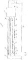
- the presentation of the Fig. 7 shows sections of a profile processing apparatus 10 according to the prior art.
- the profile processing device 10 is intended to process a profile 12.
- the profile 12 is detected on its side facing away from a tool, not shown, by means of a gripper 14 of a feed device and then moved in the directions of a double arrow 16.
- the gripper 14 is also used to transport the profile 12 further through the profile processing device.
- a total of six roller tensioners 18 are provided.
- the roll tensioners 18 are evenly distributed over the length of the profile 12 to reliably guide the profile 12 over its entire length. It will be appreciated that if profile 12 is shorter than illustrated, only some of the roller tensioners 18 will be needed.
- the roller tensioners 18 must also be moved out of the range of movement of the gripper perpendicular to the double arrow 16 in order to allow movement of the gripper 14 and, if necessary, require a large adjustment range.
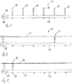
- the presentation of the Fig. 1 schematically shows a profile machining device 20 according to the invention.
- the profile machining device 20 has a machine frame 22 which stands on a ground surface 24.
- a tool 26 is arranged, which is provided for the processing of a profile 12 and which can be configured substantially in any desired manner.
- the tool 26 is shown only schematically.
- the tool 26 may for example have a sawing device with a circular saw blade, one or more drilling and milling spindles and also other tools.
- the tool 26 may, for example, also have a turntable whose axis of rotation is arranged parallel to a longitudinal direction of the profile 12, through which the profile 12 is pushed and on which a plurality of tools are arranged.
- a relative movement between the tool 26 and profile 12 is in the profile processing device 20 of Fig.
- the gripper 28 is slidably mounted on a guide rail 32 which is fixed to the machine frame 22.
- the guide rail 32 extends to just before the tool 26, so that the gripper 30 can move the profile 12 during profile machining and during transport on the tool.
- the profile 12 rests on a plurality of support rollers 34, which are arranged uniformly spaced from each other on the machine frame and, in the illustration of Fig. 1 , Both left and right of the tool 26 are arranged. On the support rollers 34, the profile 12 can thus be transported during and after a profile machining by means of the tool 12.
- the support rollers 34 are fixedly arranged in the longitudinal direction, but can at least partially perpendicular to the longitudinal direction, in Fig. 1 Thus, to be raised, or lowered, for example, to temporarily raise the profile 12 to facilitate access of the gripper 30.
- the support rollers 34 may also be referred to as guide rollers.
- the guide rail 32 and the gripper 30 form a feed device for the profile 12.
- a roll tensioner 36 is slidably disposed in the directions of the double arrow 30 further.
- the roller tensioner 36 has a tensioning roller 38, which can be delivered to the profile 12 and pulled back from the profile 12.
- the roll tensioner 36 is slidable along the entire guide rail 32 and thus can be driven into the region of the end of the profile 12 which is gripped by the gripper 30 and also, as in Fig. 1 is shown to be driven just before the tool 26.
- Fig. 1 only one roller tensioner 36 is shown. However, it may be provided a plurality of roller tensioners 36, which are then arranged on the guide rail 32 slidably.
- the guide rail 32 is provided in a manner not shown with a stator of a linear motor.
- the roller tensioner 36 is provided with a rotor of the linear motor and can thereby be moved automatically along the guide rail 32.
- the gripper 28 is also provided with a rotor of the linear motor, so that only one linear motor is required for a movement of both the gripper 28 and the roller tensioner 36 along the guide rail 32.
- the presentation of the Fig. 2 shows the profile processing device 20 of Fig. 1 in a first state, in which a tool 26 facing away from the end face of the profile 12 is to be taken.
- the profile 12 is not straight over its entire length, but is bent in the region of the gripper 28 facing the end upwards.
- the front of the gripper 28 lying end of the profile 12 could not be taken or not correctly.
- Fig. 7 a large, evenly distributed over the entire length of the Eintransport Schemes number of roll tensioners provided.
- a single roller-type tensioner 36 is sufficient to securely grasp the profile 12 at its end facing away from the tool.
- the roller tensioner 36 is moved in the region of the end of the profile 12, which faces away from the tool and which lies in front of the gripper 28 for this purpose.
- This end of the profile 12 is thereby pressed against the roller tensioner 36 opposite Auflagerolle 34 and thereby in a predefined position, namely resting on the Auflagerolle 34.
- the gripper 28 is positioned correctly to the end of the profile 12 and can grip this reliably.
- the presentation of the Fig. 4 shows the profile machining device 20 according to the invention in another state.
- a shorter profile 12 is now to be processed, but the end facing away from the tool and facing the gripper 28 is likewise lifted off the support rollers 34, since the profile 12 does not extend in a straight line over its entire length.
- the roll tensioner 36 is again moved along the guide rail 32 into the region of the end of the profile 12 lying in front of the gripper 28, as in Fig. 5 is shown.
- the profile 12 is pressed against the support roller 34 in the region of an end lying in front of the gripper 28 and the gripper 28 can grasp the profile 12 reliably.
- profiles 12 of any desired length can thus be processed, and even with a deviation from the straightness, these profiles 12 can be gripped reliably by means of the gripper 28, without a large number of roller clamps, as in profile machining devices according to the prior art 18 must be distributed uniformly over the entire Eintransport Scheme the profile processing device.
- the presentation of the Fig. 6 shows the profile machining device 20 according to the invention in another state.
- the tool 12 remote from the end of the profile 12 has been gripped by the gripper 28 and the gripper 28 pushes or pulls the profile 12 in the directions of the double arrow 30 during a profile machining relative to the tool 26, see Fig. 1 ,
- the roll tensioner 36 is now arranged during profile machining so that the profile 12 is guided as evenly as possible.
- the roller tensioner 36 is in the state of Fig. 6 this has been moved approximately to the middle of the distance between the tool and the gripper 28.
- a plurality of displaceable roller clamps 36 may be provided to guide the profile 12 safely.
- the profile-machining device 20 it is thus possible to ensure that a not-so-straight profile can be gripped securely by the gripper 28 or a feed device and, moreover, a guide distributed uniformly over the length of the profile can be ensured during profile machining. Nevertheless, the profile-machining device 20 according to the invention can handle only one or a few roller clamps 36.
Landscapes
- Engineering & Computer Science (AREA)
- Mechanical Engineering (AREA)
- Turning (AREA)
- Machine Tool Units (AREA)
- Jigs For Machine Tools (AREA)
Claims (7)
- Dispositif d'usinage de profilés comprenant un châssis de machine (22), au moins un outil (26) pour l'usinage de profilés, au moins un dispositif de serrage pour un profilé à usiner (12) et un dispositif d'avance pour déplacer un profilé à usiner (12) dans une direction de transport qui correspond à une direction longitudinale du profilé (12) à travers le dispositif d'usinage de profilés (20), le dispositif de serrage présentant au moins un dispositif de serrage à rouleaux (36) pour le guidage du profilé (12) pendant un usinage du profilé avec un déplacement simultané du profilé au moyen du dispositif d'avance, caractérisé en ce que le dispositif de serrage présente un rail de guidage (32) qui est disposé parallèlement à la direction de transport sur le châssis de machine (22), l'au moins un dispositif de serrage à rouleaux (36) étant disposé sur le rail de guidage (32) de manière déplaçable dans la direction de transport et dans la direction opposée, en ce que le rail de guidage (32) s'étend essentiellement sur toute une région d'amenée de profilés (12) jusqu'à l'outil (26), et en ce que le dispositif d'avance présente un dispositif de préhension (28) pour saisir un côté frontal d'un profilé à usiner (12), des moyens étant prévus pour détecter une position du côté frontal du profilé (12) opposé à l'outil (26) dans la région d'amenée et des moyens étant prévus pour déplacer l'au moins un dispositif de serrage à rouleaux (36) dans une région du profilé (12) qui est adjacente au côté frontal opposé à l'outil.
- Dispositif d'usinage de profilés selon la revendication 1, caractérisé en ce que sur toute la région d'amenée sont disposés des rouleaux d'appui et/ou des rouleaux de guidage (34) pour un profilé à usiner (12).
- Dispositif d'usinage de profilés selon l'une quelconque des revendications précédentes, caractérisé en ce que plusieurs dispositifs de serrage à rouleaux (36) déplaçables le long du rail de guidage (32) sont prévus.
- Dispositif d'usinage de profilés selon la revendication 3, caractérisé en ce que le rail de guidage (32) est pourvu d'un stator d'un moteur linéaire et chaque dispositif de serrage à rouleaux (36) est pourvu d'un rotor du moteur linéaire.
- Dispositif d'usinage de profilés selon l'une quelconque des revendications précédentes, caractérisé en ce que le dispositif de préhension (28) est disposé de manière déplaçable sur le rail de guidage.
- Dispositif d'usinage de profilés selon l'une quelconque des revendications précédentes, caractérisé en ce que le dispositif de préhension (28) est pourvu d'un rotor du moteur linéaire.
- Procédé pour usiner des profilés utilisant un dispositif d'usinage de profilés selon l'une quelconque des revendications précédentes, caractérisé par la détection de la position d'un côté frontal du profilé (12) opposé à l'outil (26) dans la région d'amenée, le déplacement d'au moins un dispositif de serrage à rouleaux (36) dans une région du profilé (12) qui est adjacente au côté frontal opposé à l'outil (26), l'approche d'un rouleau de serrage (38) du dispositif de serrage à rouleaux (36) dans la direction du profilé (12) et la saisie du côté frontal du profilé à usiner (12) avec un dispositif de préhension (28) du dispositif d'avance après l'approche du rouleau de serrage (38) du dispositif de serrage à rouleaux (36) jusqu'au profilé (12) dans la région du profilé (12) qui est adjacente au côté frontal du profilé (12) opposé à l'outil (26).
Applications Claiming Priority (1)
| Application Number | Priority Date | Filing Date | Title |
|---|---|---|---|
| DE102014205405.2A DE102014205405B4 (de) | 2014-03-24 | 2014-03-24 | Profilbearbeitungsvorrichtung und Verfahren zum Bearbeiten von Profilen |
Publications (2)
| Publication Number | Publication Date |
|---|---|
| EP2926942A1 EP2926942A1 (fr) | 2015-10-07 |
| EP2926942B1 true EP2926942B1 (fr) | 2017-01-11 |
Family
ID=52997824
Family Applications (1)
| Application Number | Title | Priority Date | Filing Date |
|---|---|---|---|
| EP15159239.1A Active EP2926942B1 (fr) | 2014-03-24 | 2015-03-16 | Dispositif d'usinage de profilés et procédé destiné à l'usinage de profilés |
Country Status (2)
| Country | Link |
|---|---|
| EP (1) | EP2926942B1 (fr) |
| DE (1) | DE102014205405B4 (fr) |
Cited By (1)
| Publication number | Priority date | Publication date | Assignee | Title |
|---|---|---|---|---|
| CN108788298A (zh) * | 2018-07-24 | 2018-11-13 | 浙江威力士机械有限公司 | 金属料棒切断圆锯机 |
Families Citing this family (3)
| Publication number | Priority date | Publication date | Assignee | Title |
|---|---|---|---|---|
| ITUA20163993A1 (it) * | 2016-05-31 | 2017-12-01 | F O M Ind S R L | Macchina per la lavorazione di profilati |
| CN107971576A (zh) * | 2017-12-15 | 2018-05-01 | 湖南新融创科技有限公司 | 一种五金零部件生产加工用切割装置 |
| IT201900022962A1 (it) * | 2019-12-04 | 2021-06-04 | Lorenzo Lattanzi | Dispositivo di avanzamento |
Family Cites Families (9)
| Publication number | Priority date | Publication date | Assignee | Title |
|---|---|---|---|---|
| DE1628917B1 (de) | 1967-03-30 | 1974-02-28 | Teutoburger Maschinenfabrik Gm | Vorrichtung zum Aufteilen von Formatplatten |
| US3648993A (en) * | 1970-06-30 | 1972-03-14 | Mitsubishi Heavy Ind Ltd | Work piece pressing device in automatic stack gas cutting |
| IT1169821B (it) * | 1983-09-13 | 1987-06-03 | Teax Srl | Macchina per la foratura di materiali lastriformi fragili,in paticolare di lastre in vetro e simili |
| DE4401271C2 (de) * | 1994-01-18 | 1997-06-12 | Schmidler Maschinenbau Gmbh | Abbundanlage mit Transporteinrichtungen |
| US6116126A (en) * | 1996-07-10 | 2000-09-12 | Van Den Bulcke; Marc | Method and machine for making profile pieces |
| DE19905876A1 (de) * | 1999-02-12 | 2000-08-17 | Hans Hundegger | Holzbearbeitungsanlage in Portalbauweise |
| DE20203938U1 (de) * | 2002-03-12 | 2002-06-06 | Wassmer Spezialmaschinen GmbH, 79423 Heitersheim | Bearbeitungsmaschine zum wenigstens teilweisen konturenabhängigen Ausschneiden oder Fräsen |
| DE102005002595B4 (de) | 2005-01-20 | 2007-02-08 | Holzma Plattenaufteiltechnik Gmbh | Greifeinrichtung, insbesondere Spannzange, zur Verwendung bei einer Vorschubvorrichtung für plattenförmige Werkstücke |
| DE102008026330A1 (de) * | 2008-05-31 | 2009-12-03 | Holzma Plattenaufteiltechnik Gmbh | Plattenaufteilanlage |
-
2014
- 2014-03-24 DE DE102014205405.2A patent/DE102014205405B4/de active Active
-
2015
- 2015-03-16 EP EP15159239.1A patent/EP2926942B1/fr active Active
Non-Patent Citations (1)
| Title |
|---|
| None * |
Cited By (2)
| Publication number | Priority date | Publication date | Assignee | Title |
|---|---|---|---|---|
| CN108788298A (zh) * | 2018-07-24 | 2018-11-13 | 浙江威力士机械有限公司 | 金属料棒切断圆锯机 |
| CN108788298B (zh) * | 2018-07-24 | 2019-07-23 | 浙江威力士机械有限公司 | 金属料棒切断圆锯机 |
Also Published As
| Publication number | Publication date |
|---|---|
| DE102014205405A1 (de) | 2015-09-24 |
| EP2926942A1 (fr) | 2015-10-07 |
| DE102014205405B4 (de) | 2020-06-25 |
Similar Documents
| Publication | Publication Date | Title |
|---|---|---|
| EP3197639B1 (fr) | Dispositif d'usinage | |
| EP3639971B1 (fr) | Procédé de traitement des pièces longues en bois, en matière plastique et analogue, ainsi que machine permettant de mettre en oeuvre ledit procédé | |
| EP3356098A1 (fr) | Dispositif d'usinage | |
| EP2926942B1 (fr) | Dispositif d'usinage de profilés et procédé destiné à l'usinage de profilés | |
| DE102007035743B4 (de) | Bearbeitungsstation zum Bearbeiten von plattenförmigen Werkstücken | |
| EP3215317A1 (fr) | Dispositif de serrage | |
| EP3023193B1 (fr) | Dispositif d'introduction de piece a usiner | |
| EP2404691B1 (fr) | Couronne rotative pour usinage de profilés | |
| EP2774708B1 (fr) | Scie destinée à scier au moins une pièce en forme de plaque | |
| EP2810754A1 (fr) | Procédé destiné au traitement d'un tronc d'arbre | |
| DE102014205404A1 (de) | Profilbearbeitungsvorrichtung und Verfahren zum Bearbeiten von Profilen | |
| EP2481540B1 (fr) | Dispositif de sciage d'au moins deux pièces usinées sous forme de plaques ou de piles de plaques | |
| EP2371480B1 (fr) | Centre de traitement de profilés | |
| DE3737228A1 (de) | Einrichtung zum buntaufteilen von plattenfoermigen werkstuecken | |
| WO2009030348A1 (fr) | Installation de traitement de pièces en bois, matière plastique et analogues, et procédé de traitement de telles pièces | |
| EP1764177B1 (fr) | Dispositif pour couper de barres de vitrage à longueur et procédé pour couper de barres de vitrage ou similaires | |
| EP2236232A2 (fr) | Scie mécanique | |
| EP3069837B1 (fr) | Dispositif d'usinage | |
| EP3922423B1 (fr) | Dispositif d'alimentation en pièces ou dispositif d'évacuation de pièces | |
| EP2030725B1 (fr) | Dispositif et procédé destinés à aligner des pièces à usiner | |
| DE10303136B3 (de) | Band- und Platinenabstützung für ein Schneidwerkzeug mit zwei Schneidbalken | |
| DE102011102793B3 (de) | Verfahren zur Bearbeitung der Stirnseiten von Werkstücken aus Holz, Kunststoff und dergleichen | |
| DE102012111879A1 (de) | Verfahren und Vorrichtung zum Bearbeiten von Platten | |
| DE102019003699A1 (de) | Werkstück-Bereitstellungsgruppe für eine Bearbeitungsstation | |
| DE102014219098A1 (de) | Werkstücktisch und Bearbeitungsvorrichtung mit einem Werkstücktisch |
Legal Events
| Date | Code | Title | Description |
|---|---|---|---|
| PUAI | Public reference made under article 153(3) epc to a published international application that has entered the european phase |
Free format text: ORIGINAL CODE: 0009012 |
|
| AK | Designated contracting states |
Kind code of ref document: A1 Designated state(s): AL AT BE BG CH CY CZ DE DK EE ES FI FR GB GR HR HU IE IS IT LI LT LU LV MC MK MT NL NO PL PT RO RS SE SI SK SM TR |
|
| AX | Request for extension of the european patent |
Extension state: BA ME |
|
| 17P | Request for examination filed |
Effective date: 20160122 |
|
| RBV | Designated contracting states (corrected) |
Designated state(s): AL AT BE BG CH CY CZ DE DK EE ES FI FR GB GR HR HU IE IS IT LI LT LU LV MC MK MT NL NO PL PT RO RS SE SI SK SM TR |
|
| RIC1 | Information provided on ipc code assigned before grant |
Ipc: B23Q 7/05 20060101ALI20160707BHEP Ipc: B23Q 7/04 20060101ALI20160707BHEP Ipc: B23Q 3/06 20060101AFI20160707BHEP Ipc: B23D 47/04 20060101ALI20160707BHEP |
|
| GRAP | Despatch of communication of intention to grant a patent |
Free format text: ORIGINAL CODE: EPIDOSNIGR1 |
|
| INTG | Intention to grant announced |
Effective date: 20160817 |
|
| GRAS | Grant fee paid |
Free format text: ORIGINAL CODE: EPIDOSNIGR3 |
|
| GRAJ | Information related to disapproval of communication of intention to grant by the applicant or resumption of examination proceedings by the epo deleted |
Free format text: ORIGINAL CODE: EPIDOSDIGR1 |
|
| GRAL | Information related to payment of fee for publishing/printing deleted |
Free format text: ORIGINAL CODE: EPIDOSDIGR3 |
|
| GRAP | Despatch of communication of intention to grant a patent |
Free format text: ORIGINAL CODE: EPIDOSNIGR1 |
|
| GRAA | (expected) grant |
Free format text: ORIGINAL CODE: 0009210 |
|
| INTC | Intention to grant announced (deleted) | ||
| INTG | Intention to grant announced |
Effective date: 20161128 |
|
| AK | Designated contracting states |
Kind code of ref document: B1 Designated state(s): AL AT BE BG CH CY CZ DE DK EE ES FI FR GB GR HR HU IE IS IT LI LT LU LV MC MK MT NL NO PL PT RO RS SE SI SK SM TR |
|
| REG | Reference to a national code |
Ref country code: GB Ref legal event code: FG4D Free format text: NOT ENGLISH |
|
| REG | Reference to a national code |
Ref country code: CH Ref legal event code: EP |
|
| REG | Reference to a national code |
Ref country code: AT Ref legal event code: REF Ref document number: 860816 Country of ref document: AT Kind code of ref document: T Effective date: 20170115 |
|
| REG | Reference to a national code |
Ref country code: IE Ref legal event code: FG4D Free format text: LANGUAGE OF EP DOCUMENT: GERMAN |
|
| REG | Reference to a national code |
Ref country code: DE Ref legal event code: R096 Ref document number: 502015000487 Country of ref document: DE |
|
| REG | Reference to a national code |
Ref country code: FR Ref legal event code: PLFP Year of fee payment: 3 |
|
| REG | Reference to a national code |
Ref country code: LT Ref legal event code: MG4D |
|
| REG | Reference to a national code |
Ref country code: NL Ref legal event code: MP Effective date: 20170111 |
|
| PG25 | Lapsed in a contracting state [announced via postgrant information from national office to epo] |
Ref country code: NL Free format text: LAPSE BECAUSE OF FAILURE TO SUBMIT A TRANSLATION OF THE DESCRIPTION OR TO PAY THE FEE WITHIN THE PRESCRIBED TIME-LIMIT Effective date: 20170111 |
|
| PG25 | Lapsed in a contracting state [announced via postgrant information from national office to epo] |
Ref country code: HR Free format text: LAPSE BECAUSE OF FAILURE TO SUBMIT A TRANSLATION OF THE DESCRIPTION OR TO PAY THE FEE WITHIN THE PRESCRIBED TIME-LIMIT Effective date: 20170111 Ref country code: GR Free format text: LAPSE BECAUSE OF FAILURE TO SUBMIT A TRANSLATION OF THE DESCRIPTION OR TO PAY THE FEE WITHIN THE PRESCRIBED TIME-LIMIT Effective date: 20170412 Ref country code: IS Free format text: LAPSE BECAUSE OF FAILURE TO SUBMIT A TRANSLATION OF THE DESCRIPTION OR TO PAY THE FEE WITHIN THE PRESCRIBED TIME-LIMIT Effective date: 20170511 Ref country code: NO Free format text: LAPSE BECAUSE OF FAILURE TO SUBMIT A TRANSLATION OF THE DESCRIPTION OR TO PAY THE FEE WITHIN THE PRESCRIBED TIME-LIMIT Effective date: 20170411 Ref country code: LT Free format text: LAPSE BECAUSE OF FAILURE TO SUBMIT A TRANSLATION OF THE DESCRIPTION OR TO PAY THE FEE WITHIN THE PRESCRIBED TIME-LIMIT Effective date: 20170111 Ref country code: FI Free format text: LAPSE BECAUSE OF FAILURE TO SUBMIT A TRANSLATION OF THE DESCRIPTION OR TO PAY THE FEE WITHIN THE PRESCRIBED TIME-LIMIT Effective date: 20170111 |
|
| PG25 | Lapsed in a contracting state [announced via postgrant information from national office to epo] |
Ref country code: BG Free format text: LAPSE BECAUSE OF FAILURE TO SUBMIT A TRANSLATION OF THE DESCRIPTION OR TO PAY THE FEE WITHIN THE PRESCRIBED TIME-LIMIT Effective date: 20170411 Ref country code: PL Free format text: LAPSE BECAUSE OF FAILURE TO SUBMIT A TRANSLATION OF THE DESCRIPTION OR TO PAY THE FEE WITHIN THE PRESCRIBED TIME-LIMIT Effective date: 20170111 Ref country code: PT Free format text: LAPSE BECAUSE OF FAILURE TO SUBMIT A TRANSLATION OF THE DESCRIPTION OR TO PAY THE FEE WITHIN THE PRESCRIBED TIME-LIMIT Effective date: 20170511 Ref country code: LV Free format text: LAPSE BECAUSE OF FAILURE TO SUBMIT A TRANSLATION OF THE DESCRIPTION OR TO PAY THE FEE WITHIN THE PRESCRIBED TIME-LIMIT Effective date: 20170111 Ref country code: SE Free format text: LAPSE BECAUSE OF FAILURE TO SUBMIT A TRANSLATION OF THE DESCRIPTION OR TO PAY THE FEE WITHIN THE PRESCRIBED TIME-LIMIT Effective date: 20170111 Ref country code: ES Free format text: LAPSE BECAUSE OF FAILURE TO SUBMIT A TRANSLATION OF THE DESCRIPTION OR TO PAY THE FEE WITHIN THE PRESCRIBED TIME-LIMIT Effective date: 20170111 Ref country code: RS Free format text: LAPSE BECAUSE OF FAILURE TO SUBMIT A TRANSLATION OF THE DESCRIPTION OR TO PAY THE FEE WITHIN THE PRESCRIBED TIME-LIMIT Effective date: 20170111 |
|
| REG | Reference to a national code |
Ref country code: DE Ref legal event code: R097 Ref document number: 502015000487 Country of ref document: DE |
|
| PG25 | Lapsed in a contracting state [announced via postgrant information from national office to epo] |
Ref country code: RO Free format text: LAPSE BECAUSE OF FAILURE TO SUBMIT A TRANSLATION OF THE DESCRIPTION OR TO PAY THE FEE WITHIN THE PRESCRIBED TIME-LIMIT Effective date: 20170111 Ref country code: SK Free format text: LAPSE BECAUSE OF FAILURE TO SUBMIT A TRANSLATION OF THE DESCRIPTION OR TO PAY THE FEE WITHIN THE PRESCRIBED TIME-LIMIT Effective date: 20170111 Ref country code: EE Free format text: LAPSE BECAUSE OF FAILURE TO SUBMIT A TRANSLATION OF THE DESCRIPTION OR TO PAY THE FEE WITHIN THE PRESCRIBED TIME-LIMIT Effective date: 20170111 Ref country code: CZ Free format text: LAPSE BECAUSE OF FAILURE TO SUBMIT A TRANSLATION OF THE DESCRIPTION OR TO PAY THE FEE WITHIN THE PRESCRIBED TIME-LIMIT Effective date: 20170111 |
|
| PLBE | No opposition filed within time limit |
Free format text: ORIGINAL CODE: 0009261 |
|
| STAA | Information on the status of an ep patent application or granted ep patent |
Free format text: STATUS: NO OPPOSITION FILED WITHIN TIME LIMIT |
|
| PG25 | Lapsed in a contracting state [announced via postgrant information from national office to epo] |
Ref country code: MC Free format text: LAPSE BECAUSE OF FAILURE TO SUBMIT A TRANSLATION OF THE DESCRIPTION OR TO PAY THE FEE WITHIN THE PRESCRIBED TIME-LIMIT Effective date: 20170111 Ref country code: DK Free format text: LAPSE BECAUSE OF FAILURE TO SUBMIT A TRANSLATION OF THE DESCRIPTION OR TO PAY THE FEE WITHIN THE PRESCRIBED TIME-LIMIT Effective date: 20170111 Ref country code: SM Free format text: LAPSE BECAUSE OF FAILURE TO SUBMIT A TRANSLATION OF THE DESCRIPTION OR TO PAY THE FEE WITHIN THE PRESCRIBED TIME-LIMIT Effective date: 20170111 |
|
| 26N | No opposition filed |
Effective date: 20171012 |
|
| REG | Reference to a national code |
Ref country code: IE Ref legal event code: MM4A |
|
| PG25 | Lapsed in a contracting state [announced via postgrant information from national office to epo] |
Ref country code: LU Free format text: LAPSE BECAUSE OF NON-PAYMENT OF DUE FEES Effective date: 20170316 |
|
| PG25 | Lapsed in a contracting state [announced via postgrant information from national office to epo] |
Ref country code: IE Free format text: LAPSE BECAUSE OF NON-PAYMENT OF DUE FEES Effective date: 20170316 Ref country code: SI Free format text: LAPSE BECAUSE OF FAILURE TO SUBMIT A TRANSLATION OF THE DESCRIPTION OR TO PAY THE FEE WITHIN THE PRESCRIBED TIME-LIMIT Effective date: 20170111 |
|
| REG | Reference to a national code |
Ref country code: BE Ref legal event code: MM Effective date: 20170331 |
|
| REG | Reference to a national code |
Ref country code: FR Ref legal event code: PLFP Year of fee payment: 4 |
|
| PG25 | Lapsed in a contracting state [announced via postgrant information from national office to epo] |
Ref country code: BE Free format text: LAPSE BECAUSE OF NON-PAYMENT OF DUE FEES Effective date: 20170331 |
|
| PG25 | Lapsed in a contracting state [announced via postgrant information from national office to epo] |
Ref country code: MT Free format text: LAPSE BECAUSE OF FAILURE TO SUBMIT A TRANSLATION OF THE DESCRIPTION OR TO PAY THE FEE WITHIN THE PRESCRIBED TIME-LIMIT Effective date: 20170111 |
|
| REG | Reference to a national code |
Ref country code: CH Ref legal event code: PL |
|
| PG25 | Lapsed in a contracting state [announced via postgrant information from national office to epo] |
Ref country code: LI Free format text: LAPSE BECAUSE OF NON-PAYMENT OF DUE FEES Effective date: 20180331 Ref country code: CH Free format text: LAPSE BECAUSE OF NON-PAYMENT OF DUE FEES Effective date: 20180331 |
|
| PG25 | Lapsed in a contracting state [announced via postgrant information from national office to epo] |
Ref country code: HU Free format text: LAPSE BECAUSE OF FAILURE TO SUBMIT A TRANSLATION OF THE DESCRIPTION OR TO PAY THE FEE WITHIN THE PRESCRIBED TIME-LIMIT; INVALID AB INITIO Effective date: 20150316 |
|
| PG25 | Lapsed in a contracting state [announced via postgrant information from national office to epo] |
Ref country code: CY Free format text: LAPSE BECAUSE OF FAILURE TO SUBMIT A TRANSLATION OF THE DESCRIPTION OR TO PAY THE FEE WITHIN THE PRESCRIBED TIME-LIMIT Effective date: 20170111 |
|
| PG25 | Lapsed in a contracting state [announced via postgrant information from national office to epo] |
Ref country code: MK Free format text: LAPSE BECAUSE OF FAILURE TO SUBMIT A TRANSLATION OF THE DESCRIPTION OR TO PAY THE FEE WITHIN THE PRESCRIBED TIME-LIMIT Effective date: 20170111 |
|
| PG25 | Lapsed in a contracting state [announced via postgrant information from national office to epo] |
Ref country code: AL Free format text: LAPSE BECAUSE OF FAILURE TO SUBMIT A TRANSLATION OF THE DESCRIPTION OR TO PAY THE FEE WITHIN THE PRESCRIBED TIME-LIMIT Effective date: 20170111 |
|
| REG | Reference to a national code |
Ref country code: AT Ref legal event code: MM01 Ref document number: 860816 Country of ref document: AT Kind code of ref document: T Effective date: 20200316 |
|
| PG25 | Lapsed in a contracting state [announced via postgrant information from national office to epo] |
Ref country code: AT Free format text: LAPSE BECAUSE OF NON-PAYMENT OF DUE FEES Effective date: 20200316 |
|
| P01 | Opt-out of the competence of the unified patent court (upc) registered |
Effective date: 20230525 |
|
| PGFP | Annual fee paid to national office [announced via postgrant information from national office to epo] |
Ref country code: IT Payment date: 20250331 Year of fee payment: 11 |
|
| PGFP | Annual fee paid to national office [announced via postgrant information from national office to epo] |
Ref country code: GB Payment date: 20260317 Year of fee payment: 12 |
|
| PGFP | Annual fee paid to national office [announced via postgrant information from national office to epo] |
Ref country code: DE Payment date: 20260324 Year of fee payment: 12 |
|
| PGFP | Annual fee paid to national office [announced via postgrant information from national office to epo] |
Ref country code: FR Payment date: 20260324 Year of fee payment: 12 |
|
| PGFP | Annual fee paid to national office [announced via postgrant information from national office to epo] |
Ref country code: TR Payment date: 20260306 Year of fee payment: 12 |