EP2926996A2 - Endverschluss mit einem einsatz für eine kammerrakelanordnung - Google Patents
Endverschluss mit einem einsatz für eine kammerrakelanordnung Download PDFInfo
- Publication number
- EP2926996A2 EP2926996A2 EP15155991.1A EP15155991A EP2926996A2 EP 2926996 A2 EP2926996 A2 EP 2926996A2 EP 15155991 A EP15155991 A EP 15155991A EP 2926996 A2 EP2926996 A2 EP 2926996A2
- Authority
- EP
- European Patent Office
- Prior art keywords
- seal
- insert
- abrasion resistant
- seal body
- sidewalls
- Prior art date
- Legal status (The legal status is an assumption and is not a legal conclusion. Google has not performed a legal analysis and makes no representation as to the accuracy of the status listed.)
- Withdrawn
Links
- 238000005299 abrasion Methods 0.000 claims abstract description 28
- -1 polytetrafluoroethylene Polymers 0.000 claims abstract description 7
- 239000004812 Fluorinated ethylene propylene Substances 0.000 claims abstract description 5
- 239000004813 Perfluoroalkoxy alkane Substances 0.000 claims abstract description 5
- 229920009441 perflouroethylene propylene Polymers 0.000 claims abstract description 5
- 229920011301 perfluoro alkoxyl alkane Polymers 0.000 claims abstract description 5
- 229920001343 polytetrafluoroethylene Polymers 0.000 claims abstract description 5
- 239000004810 polytetrafluoroethylene Substances 0.000 claims abstract description 5
- HQQADJVZYDDRJT-UHFFFAOYSA-N ethene;prop-1-ene Chemical group C=C.CC=C HQQADJVZYDDRJT-UHFFFAOYSA-N 0.000 claims abstract description 4
- 239000000463 material Substances 0.000 claims description 17
- 229920002799 BoPET Polymers 0.000 claims description 4
- 229930040373 Paraformaldehyde Natural products 0.000 claims description 4
- 229920006324 polyoxymethylene Polymers 0.000 claims description 4
- 239000004699 Ultra-high molecular weight polyethylene Substances 0.000 claims description 2
- 229920000785 ultra high molecular weight polyethylene Polymers 0.000 claims description 2
- 238000007774 anilox coating Methods 0.000 description 24
- 239000012530 fluid Substances 0.000 description 20
- 229920001971 elastomer Polymers 0.000 description 15
- 238000007639 printing Methods 0.000 description 10
- 238000004140 cleaning Methods 0.000 description 9
- 239000000243 solution Substances 0.000 description 6
- 238000004519 manufacturing process Methods 0.000 description 5
- 230000000712 assembly Effects 0.000 description 4
- 238000000429 assembly Methods 0.000 description 4
- 239000004809 Teflon Substances 0.000 description 3
- 229920006362 Teflon® Polymers 0.000 description 3
- 239000000853 adhesive Substances 0.000 description 3
- 230000001070 adhesive effect Effects 0.000 description 3
- 230000008859 change Effects 0.000 description 3
- 230000006835 compression Effects 0.000 description 3
- 238000007906 compression Methods 0.000 description 3
- DHKHKXVYLBGOIT-UHFFFAOYSA-N acetaldehyde Diethyl Acetal Natural products CCOC(C)OCC DHKHKXVYLBGOIT-UHFFFAOYSA-N 0.000 description 2
- 125000002777 acetyl group Chemical class [H]C([H])([H])C(*)=O 0.000 description 2
- 238000005520 cutting process Methods 0.000 description 2
- 238000002347 injection Methods 0.000 description 2
- 239000007924 injection Substances 0.000 description 2
- 238000000465 moulding Methods 0.000 description 2
- 238000011084 recovery Methods 0.000 description 2
- 238000007789 sealing Methods 0.000 description 2
- 238000003466 welding Methods 0.000 description 2
- 229920002943 EPDM rubber Polymers 0.000 description 1
- 229920002449 FKM Polymers 0.000 description 1
- 244000043261 Hevea brasiliensis Species 0.000 description 1
- 229920000459 Nitrile rubber Polymers 0.000 description 1
- 229910000831 Steel Inorganic materials 0.000 description 1
- 229920010741 Ultra High Molecular Weight Polyethylene (UHMWPE) Polymers 0.000 description 1
- 239000000654 additive Substances 0.000 description 1
- 230000004888 barrier function Effects 0.000 description 1
- 238000000576 coating method Methods 0.000 description 1
- 238000013329 compounding Methods 0.000 description 1
- 150000001875 compounds Chemical class 0.000 description 1
- 230000001010 compromised effect Effects 0.000 description 1
- 238000005538 encapsulation Methods 0.000 description 1
- 238000005516 engineering process Methods 0.000 description 1
- 230000002708 enhancing effect Effects 0.000 description 1
- 230000001747 exhibiting effect Effects 0.000 description 1
- 238000000605 extraction Methods 0.000 description 1
- 239000004744 fabric Substances 0.000 description 1
- 239000006260 foam Substances 0.000 description 1
- 239000007788 liquid Substances 0.000 description 1
- 238000003754 machining Methods 0.000 description 1
- 230000004048 modification Effects 0.000 description 1
- 238000012986 modification Methods 0.000 description 1
- 229920003052 natural elastomer Polymers 0.000 description 1
- 239000005445 natural material Substances 0.000 description 1
- 229920001194 natural rubber Polymers 0.000 description 1
- 230000002028 premature Effects 0.000 description 1
- 239000012858 resilient material Substances 0.000 description 1
- 239000010959 steel Substances 0.000 description 1
- 229920003048 styrene butadiene rubber Polymers 0.000 description 1
- 239000000725 suspension Substances 0.000 description 1
- 239000012815 thermoplastic material Substances 0.000 description 1
- 229920001187 thermosetting polymer Polymers 0.000 description 1
- 230000007704 transition Effects 0.000 description 1
- 238000007514 turning Methods 0.000 description 1
- 239000002966 varnish Substances 0.000 description 1
- 238000004073 vulcanization Methods 0.000 description 1
- XLYOFNOQVPJJNP-UHFFFAOYSA-N water Substances O XLYOFNOQVPJJNP-UHFFFAOYSA-N 0.000 description 1
Images
Classifications
-
- G—PHYSICS
- G03—PHOTOGRAPHY; CINEMATOGRAPHY; ANALOGOUS TECHNIQUES USING WAVES OTHER THAN OPTICAL WAVES; ELECTROGRAPHY; HOLOGRAPHY
- G03G—ELECTROGRAPHY; ELECTROPHOTOGRAPHY; MAGNETOGRAPHY
- G03G15/00—Apparatus for electrographic processes using a charge pattern
- G03G15/06—Apparatus for electrographic processes using a charge pattern for developing
- G03G15/08—Apparatus for electrographic processes using a charge pattern for developing using a solid developer, e.g. powder developer
- G03G15/0896—Arrangements or disposition of the complete developer unit or parts thereof not provided for by groups G03G15/08 - G03G15/0894
- G03G15/0898—Arrangements or disposition of the complete developer unit or parts thereof not provided for by groups G03G15/08 - G03G15/0894 for preventing toner scattering during operation, e.g. seals
-
- B—PERFORMING OPERATIONS; TRANSPORTING
- B41—PRINTING; LINING MACHINES; TYPEWRITERS; STAMPS
- B41F—PRINTING MACHINES OR PRESSES
- B41F31/00—Inking arrangements or devices
- B41F31/02—Ducts, containers, supply or metering devices
- B41F31/027—Ink rail devices for inking ink rollers
-
- G—PHYSICS
- G03—PHOTOGRAPHY; CINEMATOGRAPHY; ANALOGOUS TECHNIQUES USING WAVES OTHER THAN OPTICAL WAVES; ELECTROGRAPHY; HOLOGRAPHY
- G03G—ELECTROGRAPHY; ELECTROPHOTOGRAPHY; MAGNETOGRAPHY
- G03G15/00—Apparatus for electrographic processes using a charge pattern
- G03G15/06—Apparatus for electrographic processes using a charge pattern for developing
- G03G15/08—Apparatus for electrographic processes using a charge pattern for developing using a solid developer, e.g. powder developer
- G03G15/0806—Apparatus for electrographic processes using a charge pattern for developing using a solid developer, e.g. powder developer on a donor element, e.g. belt, roller
- G03G15/0817—Apparatus for electrographic processes using a charge pattern for developing using a solid developer, e.g. powder developer on a donor element, e.g. belt, roller characterised by the lateral sealing at both sides of the donor member with respect to the developer carrying direction
Definitions
- the present invention generally relates to doctor blade assemblies which define an enclosed fluid reservoir for applying fluid to a rotating roller, and more particularly relates to an abrasion resistant end seal used to seal the opposite ends of the fluid reservoir, the end seal including an integral abrasion resistant insert which engages with the roller and where the insert may serve as a rotary doctor/metering blade.
- Enclosed doctor blade assemblies are used extensively in machinery utilizing a rotating roller that picks up fluid from a reservoir and deposits the fluid onto another surface located opposite the doctor blade assembly.
- Examples of such machinery include rotary printing units such as flexographic printing machines.
- Such enclosed doctor blade assemblies can also be utilized for the application of varnish, adhesives and various specialty coatings, for example.
- the enclosed doctor blade assembly delivers ink to the surface of an engraved roller, often referred to as the anilox roll.
- the surface of the anilox roller contains engraved microscopic cells that carry and deliver a pre-determined quantity of ink to the surface of the printing plate.
- the enclosed doctor blade assembly is intended to form an intimate seal with the surface of the anilox roller.
- the top and bottom, longitudinal surfaces of the assembly are sealed by means of two doctor blades.
- the doctor blades are mounted to the reservoir and positioned in parallel, spaced relation to each other and are directed at strategic angles to engage the free edges of the doctor blades with the surface of the anilox roller.
- the doctor blades extend the full length of the anilox roller.
- the function of each doctor blade is determined by the rotational direction of the anilox roller with one blade metering the ink or other fluid from the surface of the anilox roller while the other blade simply acts in an ink containment role, holding ink within the reservoir (see, for example, U.S. Pat. No. 5,125,341 ).
- the reservoir and doctor blades contain the fluid except at the opposite ends thereof which are open and must be closed with specially configured seals to completely enclose the reservoir and ensure the fluids (e.g., printing ink and cleaning solutions) do not unintentionally leak from the enclosed fluid reservoir.
- the part of the seal that faces the radial surface of the anilox roller comes into direct contact with the surface of the anilox roller when the enclosed doctor blade assembly is put into operation.
- the remaining surfaces of the seal are in contact with the inner surfaces of the two doctor blades and the frame forming the reservoir of the enclosed doctor blade assembly.
- the surface of the anilox roller is quite hard (e.g., 1250-1300Hv (Vickers scale; equivalent to Shore C +70) and abrasive due to the fluid-holding cells engraved into it which act to coat fluid onto the roller surface as it rotates through the fluid reservoir.
- the end seals are exposed to significant abrasive wear as the anilox roller rotates, particularly at very high speeds which result in a proportional increase in the COF (coefficient of friction) and mechanical stress applied to the seals.
- New servo-drive, gearless flexographic presses have dramatically increased the machine production speeds that can be obtained.
- the end seals are also exposed to various levels of hydraulic pressure applied by the reservoir fluids (e.g., the printing ink and cleaning solutions) that are pumped into and out of the reservoir during normal operation of the press.
- the wear rate of the surface of the seals in contact with the anilox roller is thus directly proportional to the anilox roller surface abrasiveness, hydraulic pressure applied by the reservoir fluids, and the speed at which the anilox roller is turning (rpm's). This rapid wear of the seals results in a considerable decrease in productivity due to the press operator having to frequently stop the printing press to replace worn, dislodged or leaking end seals in each of the print stations.
- a typical gearless flexographic press will have between eight and ten print stations having a pair of seals in each.
- modern servo presses are typically equipped with an automatic wash-up feature that facilitates very quick transition to the next print job.
- the automatic wash-up cycle is initiated and any ink that remains in the enclosed ink reservoir from the completed job is extracted using suction and then charged (pumped) with cleaning solution.
- This cleaning cycle exposes the seals to varying degrees of negative followed by positive hydraulic pressure as ink is removed and cleaning solution is pumped/sprayed through nozzles and circulated within the reservoir of the enclosed doctor blade assembly.
- the end seal wears rapidly (similar to having unbalanced tires on a car) which, if not caught by the operator, results in a loss of intimate contact with the surface of the anilox roller which in turn allows ink to enter the area where the seal makes contact with the surface of the anilox roller.
- the printing ink enters this area (between the surface of the seal facing the roller and the anilox roller) the ink starts to dry which then adds to the rate of abrasive wear on the seal.
- Compounding the problem is that the new gearless press technology runs at 2-3 times the production speed of conventional geared presses. As such, there is a significant increase in the level of mechanical stress applied to the end seals in the rotary direction where it makes contact with the surface of the anilox roller.
- the present invention addresses the above described problems with prior art end seals by providing an end seal for an enclosed doctor blade assembly with the end seal having an abrasion resistant insert which improves the structural integrity of the end seal while also exhibiting good sealing properties and extended end seal operational life.
- the present invention addresses the problems of prior art end seals by providing an end seal for removable attachment to a doctor blade assembly.
- the end seal comprises a seal body having a bottom wall, opposite first and second sidewalls and a top edge configured to include a radius adapted to align with and seal against a roller surface.
- An abrasion resistant insert may be integrally secured within the seal body.
- the insert includes a bottom wall, opposite first and second sidewalls and a top edge configured to coincide with the body top edge so as to align with and seal against the roller surface.
- the seal body and abrasion resistant insert may each further comprise respective first and second upper angled sidewalls extending from respective opposite first and second sidewalls. The respective first and second upper angled sidewalls are aligned to engage in contacting relation with first and second doctor blades, respectively.
- the abrasion resistant insert may further include one or more holes wherein the seal body impregnates the holes. Further, one or both of the opposite first and second insert sidewalls may reside within and be encapsulated by the seal body.
- the insert bottom wall may also reside within and be encapsulated by the seal body.
- the abrasion resistant insert may have a thickness thinner than a width of the seal body such that the abrasion resistant insert is centrally located within the seal body.
- the abrasion resistant insert may be constructed of polyoxymethylene (POM) (also known as acetal), ultra-high-molecular-weight polyethylene (UHMWPE), polytetrafluoroethylene, a perfluoroalkoxy alkane or fluorinated ethylene propylene, or combinations thereof.
- more than one insert may be provided in the seal body in spaced, parallel relation to one another (e.g., two, three, four or more inserts).
- the provision of more than one insert provides added protection against leakage of fluid past the end seal in that if the first insert closest to the reservoir is compromised and fluid leaks past this first insert, the second insert which is adjacent the first insert will act as a back-up barrier to prevent further fluid leakage past the second insert, and so on should the second insert fail with end seals having more than two inserts.
- the insert or inserts may be molded within the end seal or be inserted into a groove machined into an already formed seal. If desired, the insert may be press fit within the respective groove or further secured within the end seal groove using any known and appropriate means such as adhesive or ultrasonic welding, for example.
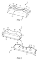
- Seal 10 includes a seal body 20 adapted to carry an integral abrasion resistant insert 30.
- Seal body 20 is preferably formed from a from a rigid yet resilient material (e.g., about 25-90 Durometer Shore A, more preferably about 60-80 Shore A, and yet more preferably about 70 Shore A) which may be injection or compression molded from an appropriate material such as, for example, thermoplastic materials or thermoset materials, EPDM rubber, Buna-N rubber, Natural Rubber, SBR Rubber, Viton, of a rubber compound that has been blended with performance enhancing additives having like characteristics, although other manufacturing processes are of course possible (e.g., cast molding, machining, SLA, vulcanization, vacuum molding, rapid prototyping, mechanical die cutting, water jet cutting, etc.).
- a rigid yet resilient material e.g., about 25-90 Durometer Shore A, more preferably about 60-80 Shore A, and yet more preferably about 70 Shore A
- an appropriate material such as, for example, thermoplastic materials or thermoset materials, EPDM rubber, Bun
- Insert 30 is preferably formed from an abrasion resistant material such as Teflon (polytetrafluoroethylene - PTFE), a perfluoroalkoxy alkane (PFA), fluorinated ethylene propylene (FEP), strip steel, biaxially-oriented polyethylene terephthalate (BoPET) (such as that sold under the trade name Mylar®), UHMWPE, POM (acetal) or other like materials.
- Teflon polytetrafluoroethylene - PTFE
- PFA perfluoroalkoxy alkane
- FEP fluorinated ethylene propylene
- Strip steel strip steel
- BoPET biaxially-oriented polyethylene terephthalate
- UHMWPE UHMWPE
- POM acetal
- abrasion resistant insert 30 is integrally formed within body 20.
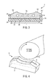
- Insert 30 may include one or more holes 32 passing therethrough. Holes 32 allow the rubber material constituting body 20 to flow through the holes during manufacture thereby impregnating the holes 32 with rubber. The rubber impregnated holes ensure that the insert is positioned and anchored correctly within the seal 10. As a result, insert 30 is an integral and permanent component of the completed seal 10. The insert 30 will not lose its position within body 20, nor will it become dislodged or delaminated from the body 20 during operational rotation of the roller 50 ( FIG. 4 ). The rubber material of body 20 residing with holes 32 of insert 30 further creates a suspension system for the insert. That is, the rubber body 20 provides the necessary compression/recovery properties that allow the abrasion resistant insert 30 to flex or otherwise absorb the mechanical tolerances inherent within the printing machine once the seal 10 is engaged against the rotating anilox roller 50 under pressure.
- seal body 20 is dimensioned to have a body width W and includes opposite body end walls 24b and 24c each having wall heights H B and a body bottom wall 24d defining a total body length L B .
- the upper surface of seal body 20 includes a top radius edge 24a situated between opposite angled upper sidewalls 24a' and 24a".
- Upper sidewalls 24a' and 24a" each taper inwardly as they extend toward the center of seal 10 and are adapted to carry optional doctor blades (not shown) as is generally known in the art.
- insert 30 is dimensioned to have an insert thickness T and includes opposite insert end walls 34b and 34c each having wall heights H I and an insert bottom wall 34d defining a total insert length L I .
- the upper surface of insert 30 includes a top radius edge 34a situated between opposite angled upper sidewalls 34a' and 34a". Again, upper sidewalls 34a' and 34a" each taper inwardly as they extend toward the center of seal 10 and are adapted to carry optional doctor blades.
- insert 30 is positioned within body 20 such that top radius edge 34a of insert 30 is present at the radius edge 24a of body 20.
- the combined top radius edges 24a and 34a are configured to be in intimate contact with rotating cylinder/roller 50.
- the thin surface of top radius edge 34a of insert 30 (as denoted by thickness "T" in FIG. 2 ) may act as a rotary doctor blade while the rubber portions of body radius edge 24a contact the rotating cylinder 50 on either side of insert 30 so as to provide two sealing surfaces to hold the ink/fluids within the enclosed chamber defined by opposing seals 10 in a fully assembled doctor blade assembly.
- the Teflon material of the abrasion resistant insert 30 wears more slowly than the rubber material constituting the remainder of end seal 10. In this manner, the frictional wear subjected to rubber body radius edge 24a is mitigated by insert top radius edge 34a of the abrasion resistant insert 30. This arrangement prolongs the operational lifetime of seal 10 while maintaining adequate liquid seals against rotating cylinder/roller 50.
- insert 30 has an insert length L I which is less than body length L B such that one or neither of insert sidewalls 34b or 34c is configured to coincide with body edge sidewalls 24b or 24c. In this manner, one or both of the insert sidewalls 34b/34c may be resident within and encapsulated by the rubber material comprising seal body 20.
- insert 30 may have a sidewall height H I smaller than body height H B such that insert bottom wall 34d does not coincide with body bottom wall 24d but is terminated within and encapsulated by the rubber material comprising seal body 20.
- the encapsulation of either or both of the insert sidewalls 34b/34c and/or the insert bottom wall 34d provides compression/recovery properties that allow the abrasion resistant insert 30 to flex or otherwise absorb the mechanical tolerances inherent within the printing machine once the seal 10 is engaged against the rotating roller 50.
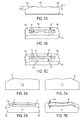
- Figures 5A-5C show another embodiment of a seal body 60 having first and second abrasion resistant inserts 62, 64 positioned in spaced, parallel relation to each other at the top radius edge 60a situated between opposite angled upper sidewalls 60a' and 60a" (see Fig. 5C ).
- the seal body upper sidewalls 60a' and 60" are dimensioned as needed to properly engage the relative positioning and geometry of the particular doctor blades used (not shown) which may or may not result in a symmetrical end seal.
- upper side walls 60a' and 60a" are shown to be of slightly different lengths with each tapering at a different angle "a” and "b” as they extend toward the center of seal 60, respectively (see Fig. 5A ).
- First and second inserts 62, 64 are either integrally molded into seal body 60 as explained above, or may be dimensioned to fit snugly within a cooperatively sized respective groove 66 and 68 machined or otherwise formed into seal body 60 (see Fig. 5B ). Inserts 62, 64 may optionally be further secured in respective grooves 66, 68 using an adhesive or ultrasonic welding, for example.
- first and second inserts 62, 64 are positioned within seal body 60 in the same manner as seal body 20 and insert 30, i.e., the exposed top radius edges 62', 64' of inserts 62, 64 are present at and preferably substantially flush with the radius edge surface 60a of body 60. If required for the particular application, inserts 62 and 64 may extend past radius edge surface 60a and into one or both of upper side walls 60a' and 60a" as shown.
- Figures 6A and 6B show another single insert embodiment having an asymmetrical seal body 70 and insert 72 having opposite ends 72a, 72b which are spaced from respective seal body end walls 70a and 70b.
- Figures 7A and 7B show yet another single insert embodiment having an asymmetrical seal body 80 and insert 82 having a thickness 82a which is larger than the inserts of the other embodiments.
- Insert 82a may be made from a fabric type material such as felt, for example, although it is understood that the inserts may be made of any desired synthetic or natural material and be of any number, thickness or length as appropriate for the particular machine application.
Landscapes
- Physics & Mathematics (AREA)
- General Physics & Mathematics (AREA)
- Inking, Control Or Cleaning Of Printing Machines (AREA)
- Paper (AREA)
- Sealing With Elastic Sealing Lips (AREA)
- Sealing Devices (AREA)
Applications Claiming Priority (2)
| Application Number | Priority Date | Filing Date | Title |
|---|---|---|---|
| US201461974192P | 2014-04-02 | 2014-04-02 | |
| US14/612,851 US9250566B2 (en) | 2014-04-02 | 2015-02-03 | End seal with insert for chambered doctor blade assembly |
Publications (2)
| Publication Number | Publication Date |
|---|---|
| EP2926996A2 true EP2926996A2 (de) | 2015-10-07 |
| EP2926996A3 EP2926996A3 (de) | 2015-11-18 |
Family
ID=52544358
Family Applications (1)
| Application Number | Title | Priority Date | Filing Date |
|---|---|---|---|
| EP15155991.1A Withdrawn EP2926996A3 (de) | 2014-04-02 | 2015-02-20 | Endverschluss mit einem einsatz für eine kammerrakelanordnung |
Country Status (2)
| Country | Link |
|---|---|
| US (2) | US9250566B2 (de) |
| EP (1) | EP2926996A3 (de) |
Families Citing this family (4)
| Publication number | Priority date | Publication date | Assignee | Title |
|---|---|---|---|---|
| US9250566B2 (en) * | 2014-04-02 | 2016-02-02 | Anthony Foley | End seal with insert for chambered doctor blade assembly |
| MX2018005177A (es) * | 2015-10-27 | 2019-05-16 | Macarbox S L U | Dispositivo para la aplicación de un fluido a un rodillo. |
| US11686391B1 (en) * | 2022-12-02 | 2023-06-27 | AJ Flexo Incorporated | End seal with self-sealing insert |
| EP4585315A1 (de) * | 2024-01-12 | 2025-07-16 | Daetwyler Swisstec Ag | Endabdichtung |
Citations (1)
| Publication number | Priority date | Publication date | Assignee | Title |
|---|---|---|---|---|
| US5125341A (en) | 1991-05-15 | 1992-06-30 | Paper Converting Machine Company | Ink unit for printing press and method |
Family Cites Families (5)
| Publication number | Priority date | Publication date | Assignee | Title |
|---|---|---|---|---|
| US5057868A (en) * | 1989-02-10 | 1991-10-15 | Minolta Camera Kabushiki Kaisha | Developing apparatus having a sealing construction for preventing a toner leakage |
| US7177565B1 (en) * | 2003-12-19 | 2007-02-13 | Cartridge Corporation Of America, Inc. | Sealing structure for a toner cartridge |
| DE202009013643U1 (de) | 2009-10-26 | 2011-03-17 | Zeljko, Kitic | Dichtelement |
| EP2425972B1 (de) | 2010-09-01 | 2016-01-13 | Anthony Foley | Selbstschmierende Dichtung für Kammerrakel |
| US9250566B2 (en) * | 2014-04-02 | 2016-02-02 | Anthony Foley | End seal with insert for chambered doctor blade assembly |
-
2015
- 2015-02-03 US US14/612,851 patent/US9250566B2/en active Active
- 2015-02-20 EP EP15155991.1A patent/EP2926996A3/de not_active Withdrawn
-
2016
- 2016-02-01 US US15/012,354 patent/US9535373B2/en active Active
Patent Citations (1)
| Publication number | Priority date | Publication date | Assignee | Title |
|---|---|---|---|---|
| US5125341A (en) | 1991-05-15 | 1992-06-30 | Paper Converting Machine Company | Ink unit for printing press and method |
Also Published As
| Publication number | Publication date |
|---|---|
| US9535373B2 (en) | 2017-01-03 |
| US20150286161A1 (en) | 2015-10-08 |
| EP2926996A3 (de) | 2015-11-18 |
| US9250566B2 (en) | 2016-02-02 |
| US20160147180A1 (en) | 2016-05-26 |
Similar Documents
| Publication | Publication Date | Title |
|---|---|---|
| US8925455B2 (en) | Self-lubricating seal for enclosed doctor blade assembly | |
| US9535373B2 (en) | End seal with insert for chambered doctor blade assembly | |
| US5983797A (en) | End seal engaging bearer of anilox roller assembly | |
| US12350924B2 (en) | Device for applying a fluid to a roller | |
| JPH08500880A (ja) | 油圧ピストン機械 | |
| JP2010069829A (ja) | チャンバー型塗工液供給装置 | |
| JP2018538179A (ja) | フレキソ印刷用装置および注入口モジュール | |
| CN106989175A (zh) | 转叶式舵机动叶一体化密封装置 | |
| US20090000753A1 (en) | Strip Means and an Improved Suction Roll for a Material Web Machine and an Arrangement and a Method for Improving the Duration of the Suction Roll | |
| ES2637998T3 (es) | Elemento de sellado hidrodinámico | |
| JP2014025411A (ja) | 遠心ポンプの軸封装置 | |
| JP4600633B2 (ja) | オイルシール | |
| JP6199895B2 (ja) | ドクターブレードチャンバシール | |
| US9085131B1 (en) | End seal for an ink chamber of a printing machine | |
| US3790180A (en) | Fluid seal with pumping action | |
| JP6378548B2 (ja) | 密封装置 | |
| US6027323A (en) | Hydraulic vane machine | |
| JP3192962U (ja) | ドクタ装置用のシール | |
| EP4378688A1 (de) | Endverschluss mit selbstdichtendem einsatz | |
| CN105604781B (zh) | 液压叶片式机器 | |
| JP2010194859A (ja) | チャンバー型塗工液供給装置 | |
| WO2017094599A1 (ja) | 密封装置 | |
| CN205859156U (zh) | 一种洗衣机骨架水封 | |
| US8474378B1 (en) | Chamber blade/sealing assembly for a printing press | |
| KR102066407B1 (ko) | 차량 브레이크 시스템의 펌프 부재용 밀봉 링 |
Legal Events
| Date | Code | Title | Description |
|---|---|---|---|
| PUAI | Public reference made under article 153(3) epc to a published international application that has entered the european phase |
Free format text: ORIGINAL CODE: 0009012 |
|
| 17P | Request for examination filed |
Effective date: 20150220 |
|
| AK | Designated contracting states |
Kind code of ref document: A2 Designated state(s): AL AT BE BG CH CY CZ DE DK EE ES FI FR GB GR HR HU IE IS IT LI LT LU LV MC MK MT NL NO PL PT RO RS SE SI SK SM TR |
|
| AX | Request for extension of the european patent |
Extension state: BA ME |
|
| PUAL | Search report despatched |
Free format text: ORIGINAL CODE: 0009013 |
|
| AK | Designated contracting states |
Kind code of ref document: A3 Designated state(s): AL AT BE BG CH CY CZ DE DK EE ES FI FR GB GR HR HU IE IS IT LI LT LU LV MC MK MT NL NO PL PT RO RS SE SI SK SM TR |
|
| AX | Request for extension of the european patent |
Extension state: BA ME |
|
| RIC1 | Information provided on ipc code assigned before grant |
Ipc: B41F 31/02 20060101AFI20151012BHEP |
|
| GRAP | Despatch of communication of intention to grant a patent |
Free format text: ORIGINAL CODE: EPIDOSNIGR1 |
|
| INTG | Intention to grant announced |
Effective date: 20180321 |
|
| STAA | Information on the status of an ep patent application or granted ep patent |
Free format text: STATUS: THE APPLICATION IS DEEMED TO BE WITHDRAWN |
|
| 18D | Application deemed to be withdrawn |
Effective date: 20180801 |