EP2927023B1 - Enveloppe de support pour un engrenage différentiel d'un essieu et ensemble de tige de piste - Google Patents
Enveloppe de support pour un engrenage différentiel d'un essieu et ensemble de tige de piste Download PDFInfo
- Publication number
- EP2927023B1 EP2927023B1 EP14196010.4A EP14196010A EP2927023B1 EP 2927023 B1 EP2927023 B1 EP 2927023B1 EP 14196010 A EP14196010 A EP 14196010A EP 2927023 B1 EP2927023 B1 EP 2927023B1
- Authority
- EP
- European Patent Office
- Prior art keywords
- track rod
- support
- mounting
- casing
- rod assembly
- Prior art date
- Legal status (The legal status is an assumption and is not a legal conclusion. Google has not performed a legal analysis and makes no representation as to the accuracy of the status listed.)
- Active
Links
Images

Classifications
-
- B—PERFORMING OPERATIONS; TRANSPORTING
- B60—VEHICLES IN GENERAL
- B60B—VEHICLE WHEELS; CASTORS; AXLES FOR WHEELS OR CASTORS; INCREASING WHEEL ADHESION
- B60B35/00—Axle units; Parts thereof ; Arrangements for lubrication of axles
- B60B35/003—Steerable axles
-
- B—PERFORMING OPERATIONS; TRANSPORTING
- B60—VEHICLES IN GENERAL
- B60K—ARRANGEMENT OR MOUNTING OF PROPULSION UNITS OR OF TRANSMISSIONS IN VEHICLES; ARRANGEMENT OR MOUNTING OF PLURAL DIVERSE PRIME-MOVERS IN VEHICLES; AUXILIARY DRIVES FOR VEHICLES; INSTRUMENTATION OR DASHBOARDS FOR VEHICLES; ARRANGEMENTS IN CONNECTION WITH COOLING, AIR INTAKE, GAS EXHAUST OR FUEL SUPPLY OF PROPULSION UNITS IN VEHICLES
- B60K17/00—Arrangement or mounting of transmissions in vehicles
- B60K17/04—Arrangement or mounting of transmissions in vehicles characterised by arrangement, location or kind of gearing
- B60K17/16—Arrangement or mounting of transmissions in vehicles characterised by arrangement, location or kind of gearing of differential gearing
-
- B—PERFORMING OPERATIONS; TRANSPORTING
- B60—VEHICLES IN GENERAL
- B60B—VEHICLE WHEELS; CASTORS; AXLES FOR WHEELS OR CASTORS; INCREASING WHEEL ADHESION
- B60B35/00—Axle units; Parts thereof ; Arrangements for lubrication of axles
- B60B35/12—Torque-transmitting axles
- B60B35/16—Axle housings
-
- B—PERFORMING OPERATIONS; TRANSPORTING
- B60—VEHICLES IN GENERAL
- B60B—VEHICLE WHEELS; CASTORS; AXLES FOR WHEELS OR CASTORS; INCREASING WHEEL ADHESION
- B60B2320/00—Manufacturing or maintenance operations
- B60B2320/10—Assembling; disassembling
-
- B—PERFORMING OPERATIONS; TRANSPORTING
- B60—VEHICLES IN GENERAL
- B60Y—INDEXING SCHEME RELATING TO ASPECTS CROSS-CUTTING VEHICLE TECHNOLOGY
- B60Y2200/00—Type of vehicle
- B60Y2200/20—Off-Road Vehicles
-
- B—PERFORMING OPERATIONS; TRANSPORTING
- B62—LAND VEHICLES FOR TRAVELLING OTHERWISE THAN ON RAILS
- B62D—MOTOR VEHICLES; TRAILERS
- B62D7/00—Steering linkage; Stub axles or their mountings
- B62D7/20—Links, e.g. track rods
-
- F—MECHANICAL ENGINEERING; LIGHTING; HEATING; WEAPONS; BLASTING
- F16—ENGINEERING ELEMENTS AND UNITS; GENERAL MEASURES FOR PRODUCING AND MAINTAINING EFFECTIVE FUNCTIONING OF MACHINES OR INSTALLATIONS; THERMAL INSULATION IN GENERAL
- F16H—GEARING
- F16H57/00—General details of gearing
- F16H57/02—Gearboxes; Mounting gearing therein
- F16H57/037—Gearboxes for accommodating differential gearings
-
- Y—GENERAL TAGGING OF NEW TECHNOLOGICAL DEVELOPMENTS; GENERAL TAGGING OF CROSS-SECTIONAL TECHNOLOGIES SPANNING OVER SEVERAL SECTIONS OF THE IPC; TECHNICAL SUBJECTS COVERED BY FORMER USPC CROSS-REFERENCE ART COLLECTIONS [XRACs] AND DIGESTS
- Y10—TECHNICAL SUBJECTS COVERED BY FORMER USPC
- Y10T—TECHNICAL SUBJECTS COVERED BY FORMER US CLASSIFICATION
- Y10T29/00—Metal working
- Y10T29/49—Method of mechanical manufacture
- Y10T29/49826—Assembling or joining
- Y10T29/4984—Retaining clearance for motion between assembled parts
Definitions
- This invention relates to a support casing for a differential gear of a driving and steering axle of a vehicle, the casing being adapted to mount a track rod assembly, and to a method of assembling a track rod assembly to such a casing.
- Some vehicles particularly those which are used off-highway, employ a driving and steering axle; such vehicles are typically all wheel drive, and a steering axle may be at the front or at the back, or in both locations.
- a steering axle requires a track rod assembly to couple the pivotable wheel hubs of the axle, and this assembly may be connected to a conventional steering box, a steering rack, or a powered actuator responsive to movement of a steering wheel or the like.
- German patent application with publication number DE10031597A1 describes a support casing according the preamble of claim 1.
- the range of wheel suspension movement is very large, and accordingly it is desirable to mount the track rod assembly, with respect to the corresponding axle, so as to avoid bump/steer effects which may occur with a track rod assembly mounted with respect to the vehicle body.
- a hydraulic barrel-type actuator is inserted in annular mounts of an axle, and has opposed track rods attached on the hub steering arms by conventional ball-jointed track rod ends.
- Such track rod ends typically comprise a female threaded body for attachment to a male threaded track rod, and a conventional taper pin for insertion through a tapered aperture of a steering arm; the taper pin includes a screw-threaded tip to receive a securing nut; the male/female attachment to the track rod may be reversed in some cases, and the taper pin may point up or down.
- the track rod assembly may be in front or behind the axle, with respect to the normal direction of vehicle movement.
- the track rod actuator components are attached to the axle casing, and then the track rod ends are attached to the track rods before the taper pins are coupled to the respective steering arms.
- the threaded connection of track rod and track rod end is often adjusted to set the length of the track rod assembly, and hence the toe-in or toe-out of the wheels of the axle.
- a track rod assembly including attached track rod ends, to minimize attachment operations during vehicle assembly and to obviate delays due to problematic assembly and adjustment.
- the radial extension (taper pin height) of a track rod end is typically greater than the bore of the annular mounts of the axle, so that insertion of a track rod assembly therethrough is obstructed.
- a support casing for the differential gear of a driving and steering axle comprising a nose defining a pinion shaft axis and support arms defining a crown-wheel axis, the casing further comprising a support mounting extending outwards therefrom from a root to a tip and in the extension direction of said nose, the support mounting being arranged to support a track rod assembly for the axle, wherein the support mounting comprises a through bore arranged to receive a cylindrical actuator, the bore having a diameter less than the radial extension of a track rod end of the track rod assembly, and characterized in that the support mounting has a slot extending outwardly of said bore and arranged to allow passage of the taper pin of the track rod end, wherein the slot extends towards said root.
- the arrangement of the invention permits a track rod assembly with track rod ends to be passed through the support mounting for attachment to the corresponding steering arm of one vehicle hub. Accordingly the track rod ends may be pre-assembled, and the length of the track rod assembly may be pre-set. As a result attachment and adjustment at the vehicle assembly line is simplified and the track rod assembly may be supplied as a unitary component.
- the slot is straight, and may be 'as cast'.
- the slot is preferably oblique with respect to the pinion shaft axis and in one embodiment extends generally obliquely away from the operating envelope of the crown wheel and differential gear.
- the axle is preferably a hypoid bevel design in which the pinion axis and crown wheel axis do not coincide, but other kinds of bevel gear are possible.
- the actuator of the track rod assembly may be hydraulic or electric, and typically comprises a cylindrical body within which a piston or like member reciprocates to move both track rods in unison.
- the support casting further includes an attachment mounting extending from the casing and being spaced from said support mounting, wherein the attachment mounting has a through bore with a diameter less than the radial extent of the track rod end, and wherein the through bores of the support mounting and the attachment mounting are aligned; the through bores are substantially of the same diameter.
- This arrangement gives a secure mounting for the actuator, generally at the mid-point of the axle adjacent the differential case.
- the actuator is preferably attached solely at the attachment mounting.
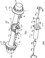
- Fig. 1 illustrates a driving and steering axle 10 of an off-highway construction vehicle.
- the axle consists of a tubular main housing 11 to which is mounted an axle drive head casing 12 having a nose 13 for supporting a driving pinion (not shown).
- the ends of the housing support conventional wheel hub swivels 14 mounted on substantially vertical steering axes 15.
- the hub swivels 14 include respective steering arms 16 connected by a track rod assembly 17, with a powered actuator 18 mounted to the drive head casing 12 as will be described below.
- a conventional crown wheel for meshing with the driving pinion, a differential gear, and opposed side shafts for driving the wheel hubs 19.
- the track rod assembly 17 has a centrally mounted cylindrical actuator 18, which may for example be hydraulic or electric, and opposed track rods 21a, 21b which are in use reciprocated in unison to one side or the other.
- Each track rod generally comprises a male threaded outer end to which the female threaded socket of a respective track rod end 22a 22b is attached.
- the respective inner ends of the track rods include a ball joint 23a, 23b which allows articulation and relative rotation to permit adjustment of the overall length of the assembly 17.
- the cylindrical body of the actuator 18 is received within close-fitting annular support and attachment mounts 24, 25, which will be further described, and is retained at one side to the attachment mount by a suitable actuator flange 26 and screws 27.
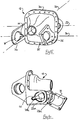
- the conventional axle drive head casing 12 is illustrated in greater detail in Fig. 3 and comprises a one-piece casting, e.g. of cast iron, having a tubular nose 13 to receive a driving pinion supported by rolling element bearings on pinion axis 30.
- Two ears 31 of the same general shape extend oppositely to the nose 13 and define a generally orthogonal crown wheel axis 32 by means of a pair of circular bearing housings 33.
- a mounting flange 34 orthogonal to axis 30 has a peripheral array of holes to receive threaded fasteners of the main axle housing 11, so that the ears 31 are in use within the housing whereas the nose protrudes outwardly towards a drive or propeller shaft (not shown).
- the illustrated axle is for hypoid bevel gear arrangement (the pinion and crown wheel axes are not coincident), but a spiral bevel gear arrangement is also possible.
- annular support and attachment mountings 24, 25 Protruding on the nose side of the casing 12 are annular support and attachment mountings 24, 25 which are parallel to and below crown wheel axis 32, and to either side of the pinion axis 30.
- These mounts define an assembly axis 34 of the actuator 18, and comprise circular bores 35 of substantially the same diameter, adapted to receive the cylindrical actuator 18 in a close sliding fit.
- the bores 35 have diameters of 87 mm and 88 mm; the larger diameter ensuring free passage through the attachment mounting 25.
- the mountings typically are an integral part of the casting of the casing 12.
- the actuator 18 Upon assembly of the axle, the actuator 18 is installed from the right side (as viewed) and attached by the screws 27. The left end of the actuator (as viewed) is a close sliding fit in the mount 24.
- the track rods 21a, 21b may be pre-attached since they can pass through the mounts 24, 25.
- the track rod ends 22a, 22b are then attached to the track rods before the tapered pins 28a, 28b are attached to respective steering arms 16.
- the toe of the axle (determined by the length of the track rod assembly) is set by screwing the track rod ends more or less on respective track rods, and this may be done before or after connection of the pins 28a, 28b and steering arms 16.
- the track rod ends 22a 22b cannot be pre-assembled because the radial extent of the pins 28a, 28b is sufficient to prevent the left-most (as viewed) from passing through both annular mounts 24.
- Figs. 4-6 The invention is illustrated in Figs. 4-6 , and components common to Figs. 1-3 carry the same reference numerals.
- the drive head casing 12 of Fig. 4 is identical to that of Fig. 3 save that the annular support mount 24 includes a slot 41 directed rearwardly with respect to the nose 13, and on the side of the ears 31.
- the slot 41 is also directed obliquely downwardly and away from the crown wheel axis 32, as illustrated, at a diverging angle in the range 10-20°.
- Fig. 6 illustrates the invention in use with a partly installed track rod assembly including pre-assembled track rod ends.
- the track rod end 22a has a pin height which exceeds the diameter of the circular bores 35.
- the track rod end 22a can be manoeuvred therethrough by articulation of the actuator 18 and corresponding track rod 21a.
- the track rod end 22a cannot be manoeuvred through the bore of the annular support mount 24 because movement is constrained by the track rod and/or actuator fouling the attachment mount 25.
- the slot 41 provides clearance for the taper pin 28a, thus permitting installation and connection of the actuator, and coupling of the track rod ends.
- the arrangement of the invention allows a pre-assembled track rod assembly, including track rod ends, to be installed without the necessity of making separate connection of at least one track rod end on the axle or vehicle assembly line. Delay and risk of misassembly is thus mitigated, and moreover the entire track rod assembly can be completed and checked away from the assembly line. In the case of a bought-out item, the integrity of the complete track rod assembly is not compromised during installation thereof.
- the strength of the actuator attachment mount 25 is not substantially compromised. Facing the slot generally in the direction of the crown wheel axis ensures that the thin outer circumference of the annular mount 24 is not weakened, nor is this portion required to be enlarged or thickened. The hoop strength of the annular mount 24 is also substantially unaffected. Pointing the slot generally downwardly (as viewed), and thus away from the pinion axis, ensures that the strength of the casing, in particular the relationship of the pinion axis and crown wheel axis, is also substantially unaffected.
- the slot 41 should generally be close-fitting to the pin 28a, but that the size thereof will be dependent on the pin diameter and length.
- the slot 41 may be straight sided, but need not be. In one embodiment the slot is 'as cast' so that additional machining of the annular support mount 24 is not required.
- a minor advantage of the slot 24 is a reduction in mass of the casing 12, and in the cost of manufacture thereof.
- a significant advantage is that the axle drive head casing is substantially identical to the prior art component, and can thus be manufactured and machined in an identical manner.
- the size and shape of the slot 41 can be adjusted, if required, to suit different sizes of track rod end, and may of course be a machined surface if desired.
- the invention has been described in relation to an axle drive head casing, but it will be appreciated that it is applicable to any separable part of a differential case of an axle assembly, or directly to a differential case or directly to a main axle housing. Also it will be understood that the bore of the attachment mount 25 may be a little larger than the bore of the support mount 24 if the actuator is stepped outwardly towards the mounting flange.
Landscapes
- Engineering & Computer Science (AREA)
- Mechanical Engineering (AREA)
- Steering-Linkage Mechanisms And Four-Wheel Steering (AREA)
- Chemical & Material Sciences (AREA)
- Combustion & Propulsion (AREA)
- Transportation (AREA)
- Vehicle Body Suspensions (AREA)
- General Engineering & Computer Science (AREA)
- Retarders (AREA)
Claims (15)
- Logement support (12) pour l'engrenage différentiel d'un essieu moteur et directeur (10), le logement support comprenant un nez (13) définissant un axe d'arbre de pignon et des bras support définissant un axe de couronne de différentiel (32), logement support, à partir duquel un support de montage (24, 25) s'étend vers l'extérieur, à savoir, à partir de la naissance vers un bout et dans la direction d'extension dudit nez, le support de montage étant conçu de manière à supporter un ensemble de barre d'accouplement (17) pour l'essieu, le support de montage comprenant un alésage traversant conçu de manière à recevoir un actionneur cylindrique, l'alésage traversant présentant un diamètre inférieur à l'extension radiale d'une extrémité de barre d'accouplement de l'ensemble de barre d'accouplement, ledit logement support étant caractérisé en ce que le support de montage présente une fente (41) qui s'étend à partir dudit alésage traversant vers l'extérieur et est conçue de manière à permettre le passage d'un goujon conique de l'extrémité de barre d'accouplement, la fente s'étendant vers ladite naissance.
- Logement support (12) suivant la revendication 1, dans lequel ladite fente (41) est essentiellement droite.
- Logement support (12) suivant la revendication 2, dans lequel la direction de ladite fente (41) n'est pas parallèle audit axe d'arbre de pignon.
- Logement support (12) suivant la revendication 2, dans lequel la fente (41) est orientée de manière oblique par rapport audit axe d'arbre de pignon, la fente présentant, de préférence, une extrémité fermée et une extrémité ouverte, l'extrémité ouverte étant plus près de l'axe d'arbre de pignon que l'extrémité fermée.
- Logement support (12) suivant une quelconque des revendications précédentes, dans lequel ledit support de montage (24, 25) est essentiellement plan et s'étend dans la direction dudit axe d'arbre de pignon, un plan étant, de préférence, défini par ledit axe d'arbre de pignon, ledit plan étant parallèle audit axe de couronne de différentiel (32) et ledit support de montage étant essentiellement orthogonal audit plan.
- Logement support (12) suivant une quelconque des revendications précédentes, à partir duquel s'étend en plus un montage de fixation (25) présentant un écart par rapport audit support de montage (24), ledit montage de fixation ayant un alésage traversant d'un diamètre inférieur à l'extension radiale d'une extrémité de barre d'accouplement d'un ensemble de barre d'accouplement et lesdits alésages traversants dudit support de montage et dudit montage de fixation étant alignés.
- Logement support (12) suivant la revendication 6, dans lequel ledit montage de fixation (25) est essentiellement plan.
- Logement support (12) suivant la revendication 6 ou 7, dans lequel lesdits alésages traversants présentent essentiellement le même diamètre.
- Logement support (12) suivant une quelconque des revendications 6 à 8, dans lequel lesdits alésages traversants sont destinés à un montage coulissant sans jeu avec le corps cylindrique d'un actionneur cylindrique.
- Logement support (12) suivant une quelconque des revendications 6 à 9, dans lequel ledit montage de fixation (25) est adapté à être fixé à une bride d'un actionneur cylindrique, le côté de fixation de ladite bride étant, de préférence, opposé audit support de montage (24).
- Logement support (12) suivant une quelconque des revendications 6 à 10, dans lequel lesdits alésages traversants définissent un axe d'actionneur parallèle audit axe de couronne de différentiel (32), ledit support de montage (24) et ledit montage de fixation (25) se situant, de préférence, sur des plans parallèles de chaque côté dudit axe d'arbre de pignon.
- Logement support (12) suivant une quelconque des revendications précédentes et incluant en plus un pignon sur l'axe d'arbre de pignon et une couronne de différentiel sur l'axe de couronne de différentiel (32).
- Essieu (10) comprenant un logement support (12) suivant une quelconque des revendications précédentes, l'essieu incluant en plus un ensemble de barre d'accouplement (17) qui comprend un actionneur hydraulique cylindrique (18), des barres d'accouplement opposées (21a, 21b) et des extrémités de barre d'accouplement respectives préalablement fixées (22a, 22b), à partir de chacune desquelles un goujon conique (28a) s'étend dans une direction essentiellement radiale par rapport à l'axe de la barre d'accouplement respective, l'ensemble de barre d'accouplement étant adapté à être monté en passant une extrémité de barre d'accouplement à travers le support de montage (24, 25) au moyen du goujon conique qui passe à travers ladite fente (41).
- Véhicule tout terrain comprenant l'essieu (10) suivant la revendication 13.
- Procédé d'assemblage d'un axe (10) comprenant les étapes suivantes qui consistent à• fournir un logement support (12) suivant la revendication 6,• fournir un ensemble de barre d'accouplement (17) avec des extrémités de barre d'accouplement (22a, 22b) préalablement fixées,• déplacer une extrémité de la barre d'accouplement axialement à travers ledit montage de fixation (25),• orienter l'ensemble de barre d'accouplement de manière à aligner le goujon conique d'une extrémité de barre d'accouplement avec ladite fente (41),• déplacer l'ensemble de barre d'accouplement axialement à travers l'alésage du support de montage (24) de manière que le goujon conique passe à travers la fente, et• monter ledit ensemble de barre d'accouplement sur ledit montage de fixation.
Applications Claiming Priority (1)
| Application Number | Priority Date | Filing Date | Title |
|---|---|---|---|
| GB1322714.5A GB2521454A (en) | 2013-12-20 | 2013-12-20 | Support casing for a differential gear of an axle and track rod assembly |
Publications (3)
| Publication Number | Publication Date |
|---|---|
| EP2927023A2 EP2927023A2 (fr) | 2015-10-07 |
| EP2927023A3 EP2927023A3 (fr) | 2016-03-23 |
| EP2927023B1 true EP2927023B1 (fr) | 2017-09-20 |
Family
ID=50071252
Family Applications (1)
| Application Number | Title | Priority Date | Filing Date |
|---|---|---|---|
| EP14196010.4A Active EP2927023B1 (fr) | 2013-12-20 | 2014-12-03 | Enveloppe de support pour un engrenage différentiel d'un essieu et ensemble de tige de piste |
Country Status (5)
| Country | Link |
|---|---|
| US (1) | US9770946B2 (fr) |
| EP (1) | EP2927023B1 (fr) |
| JP (1) | JP6422329B2 (fr) |
| CN (1) | CN104724168B (fr) |
| GB (1) | GB2521454A (fr) |
Families Citing this family (6)
| Publication number | Priority date | Publication date | Assignee | Title |
|---|---|---|---|---|
| US9156312B1 (en) * | 2014-04-29 | 2015-10-13 | Dromos Usa Inc. | Drive axle for an agricultural or industrial vehicle |
| USD782280S1 (en) * | 2014-10-15 | 2017-03-28 | Claussen Technology, Llc | Spray hood attachment system |
| US9925554B2 (en) | 2014-10-31 | 2018-03-27 | Claussen Technology, Inc. | Sprayer apparatus and systems |
| JP6754630B2 (ja) * | 2016-06-27 | 2020-09-16 | 株式会社クボタ | 車軸装置 |
| IT201800003802A1 (it) * | 2018-03-21 | 2019-09-21 | Babini Giorgio Srl | Gruppo di sterzatura per ruote di veicoli |
| CN111267550B (zh) * | 2020-03-31 | 2024-11-12 | 张成龙 | 一种转向承重车桥 |
Family Cites Families (17)
| Publication number | Priority date | Publication date | Assignee | Title |
|---|---|---|---|---|
| BR8507238A (pt) * | 1984-08-29 | 1987-10-27 | Zahnradfabrik Friedrichshafen | Ativacao de uma borboleta diferencial |
| JP2965258B2 (ja) * | 1989-12-09 | 1999-10-18 | ヤンマーディーゼル株式会社 | トラクターのステアリング機構 |
| IT1236484B (it) * | 1989-12-15 | 1993-03-09 | Carraro Spa | Assale sterzante a carreggiata variabile |
| US5094312A (en) * | 1990-12-27 | 1992-03-10 | Dana Corporation | Hydraulic cylinder for steering axle |
| JPH10114277A (ja) * | 1996-10-09 | 1998-05-06 | Nissan Diesel Motor Co Ltd | 急角度転舵用駆動ユニット及びこれを用いた前後輪操舵全輪駆動型車両 |
| US6039143A (en) * | 1997-06-02 | 2000-03-21 | General Motors Corporation | Steerable drive axle with electrically-powered steering apparatus |
| US6196349B1 (en) * | 1999-06-30 | 2001-03-06 | Dana Corporation | Steering cylinder to axle housing retention system |
| ITBO20020578A1 (it) * | 2002-09-13 | 2004-03-14 | Cnh Italia Spa | Assale per veicoli. |
| JP4156444B2 (ja) * | 2003-06-02 | 2008-09-24 | 株式会社 神崎高級工機製作所 | 油圧式操舵機構 |
| EP2174816B1 (fr) * | 2008-02-13 | 2012-06-06 | Kanzaki Kokyukoki Mfg. Co., Ltd. | Dispositif de moteur de roue |
| US8544579B2 (en) * | 2008-05-13 | 2013-10-01 | Caterpillar Inc. | Axle assembly for electric drive machine |
| JP5189963B2 (ja) * | 2008-11-14 | 2013-04-24 | ヤンマー株式会社 | 作業車両 |
| US8441112B2 (en) * | 2010-10-01 | 2013-05-14 | Headway Technologies, Inc. | Method of manufacturing layered chip package |
| CN201856811U (zh) * | 2010-10-19 | 2011-06-08 | 奇瑞汽车股份有限公司 | 一种装有齿轮齿条式转向器的轻型卡车 |
| CN202413287U (zh) * | 2011-12-31 | 2012-09-05 | 十堰方圆大地桥业制造有限公司 | 一种转向驱动桥 |
| DE102012011573A1 (de) * | 2012-06-13 | 2013-12-19 | Claas Selbstfahrende Erntemaschinen Gmbh | Lenkachse für landwirtschaftliche Fahrzeuge |
| CN102774239B (zh) * | 2012-07-25 | 2013-12-04 | 南京创捷和信汽车零部件有限公司 | 前转向驱动桥总成 |
-
2013
- 2013-12-20 GB GB1322714.5A patent/GB2521454A/en not_active Withdrawn
-
2014
- 2014-12-03 EP EP14196010.4A patent/EP2927023B1/fr active Active
- 2014-12-18 US US14/576,057 patent/US9770946B2/en active Active
- 2014-12-19 JP JP2014257066A patent/JP6422329B2/ja not_active Expired - Fee Related
- 2014-12-22 CN CN201410808332.2A patent/CN104724168B/zh active Active
Non-Patent Citations (1)
| Title |
|---|
| None * |
Also Published As
| Publication number | Publication date |
|---|---|
| JP2015120509A (ja) | 2015-07-02 |
| CN104724168A (zh) | 2015-06-24 |
| US9770946B2 (en) | 2017-09-26 |
| EP2927023A3 (fr) | 2016-03-23 |
| EP2927023A2 (fr) | 2015-10-07 |
| GB2521454A (en) | 2015-06-24 |
| GB201322714D0 (en) | 2014-02-05 |
| CN104724168B (zh) | 2018-06-15 |
| US20150174958A1 (en) | 2015-06-25 |
| JP6422329B2 (ja) | 2018-11-14 |
Similar Documents
| Publication | Publication Date | Title |
|---|---|---|
| EP2927023B1 (fr) | Enveloppe de support pour un engrenage différentiel d'un essieu et ensemble de tige de piste | |
| CN102245460B (zh) | 尤其用于后轮转向系统的转向装置 | |
| EP3176057B1 (fr) | Ensemble joint à rotule de direction comportant un ensemble de boulon d'arrêt et procédé de fabrication | |
| DE102008026385B4 (de) | Gelenk für ein Fahrzeuglenk- und -aufhängungssystem | |
| US8327541B2 (en) | Method of assembling a differential mechanism | |
| AU2016235526B2 (en) | Steering knuckles with integrated brake mounting provisions | |
| US20190232747A1 (en) | In-wheel motor drive device | |
| US10625778B2 (en) | Steerable knuckle apparatus and related methods | |
| US10850585B2 (en) | Strut-type suspension apparatus | |
| US20250196625A1 (en) | One-piece portal wheel end mounting system | |
| US8657316B1 (en) | Rear axle support assembly | |
| EP2812593B1 (fr) | Joint universel et fourche | |
| US20150232123A1 (en) | Steering knuckle assembly | |
| WO2013083443A1 (fr) | Roue de véhicule en matières plastiques renforcées par fibres | |
| CN105202016B (zh) | 具有轻合金旋翼毂的轮毂轴承 | |
| EP1605178A2 (fr) | Dispositif de bride pour supporter les coussinets et l'embout d'un arbre d'entraínement | |
| US5538273A (en) | Caser adjustment apparatus | |
| US20140042722A1 (en) | Axle Assembly | |
| CN105090260A (zh) | 联接组件和将第一构件和第二构件分离的方法 | |
| US20080084043A1 (en) | Vehicle suspension system and method | |
| US10286954B2 (en) | Device for adjusting camber and/or toe of a vehicle wheel | |
| CN110239611A (zh) | 全地形车及其转向系统 | |
| CN210555085U (zh) | 全地形车及其转向系统 | |
| CN112874762A (zh) | 一种起落架的撑杆组件及其装配方法 | |
| CN213007406U (zh) | 一种可调节车轴 |
Legal Events
| Date | Code | Title | Description |
|---|---|---|---|
| PUAI | Public reference made under article 153(3) epc to a published international application that has entered the european phase |
Free format text: ORIGINAL CODE: 0009012 |
|
| AK | Designated contracting states |
Kind code of ref document: A2 Designated state(s): AL AT BE BG CH CY CZ DE DK EE ES FI FR GB GR HR HU IE IS IT LI LT LU LV MC MK MT NL NO PL PT RO RS SE SI SK SM TR |
|
| AX | Request for extension of the european patent |
Extension state: BA ME |
|
| PUAL | Search report despatched |
Free format text: ORIGINAL CODE: 0009013 |
|
| AK | Designated contracting states |
Kind code of ref document: A3 Designated state(s): AL AT BE BG CH CY CZ DE DK EE ES FI FR GB GR HR HU IE IS IT LI LT LU LV MC MK MT NL NO PL PT RO RS SE SI SK SM TR |
|
| AX | Request for extension of the european patent |
Extension state: BA ME |
|
| RIC1 | Information provided on ipc code assigned before grant |
Ipc: F16H 57/037 20120101ALI20160216BHEP Ipc: B60B 35/16 20060101AFI20160216BHEP Ipc: B60B 35/00 20060101ALI20160216BHEP |
|
| 17P | Request for examination filed |
Effective date: 20160427 |
|
| RBV | Designated contracting states (corrected) |
Designated state(s): AL AT BE BG CH CY CZ DE DK EE ES FI FR GB GR HR HU IE IS IT LI LT LU LV MC MK MT NL NO PL PT RO RS SE SI SK SM TR |
|
| 17Q | First examination report despatched |
Effective date: 20160929 |
|
| GRAJ | Information related to disapproval of communication of intention to grant by the applicant or resumption of examination proceedings by the epo deleted |
Free format text: ORIGINAL CODE: EPIDOSDIGR1 |
|
| STAA | Information on the status of an ep patent application or granted ep patent |
Free format text: STATUS: GRANT OF PATENT IS INTENDED |
|
| GRAP | Despatch of communication of intention to grant a patent |
Free format text: ORIGINAL CODE: EPIDOSNIGR1 |
|
| INTG | Intention to grant announced |
Effective date: 20170407 |
|
| GRAS | Grant fee paid |
Free format text: ORIGINAL CODE: EPIDOSNIGR3 |
|
| GRAA | (expected) grant |
Free format text: ORIGINAL CODE: 0009210 |
|
| STAA | Information on the status of an ep patent application or granted ep patent |
Free format text: STATUS: THE PATENT HAS BEEN GRANTED |
|
| AK | Designated contracting states |
Kind code of ref document: B1 Designated state(s): AL AT BE BG CH CY CZ DE DK EE ES FI FR GB GR HR HU IE IS IT LI LT LU LV MC MK MT NL NO PL PT RO RS SE SI SK SM TR |
|
| REG | Reference to a national code |
Ref country code: GB Ref legal event code: FG4D |
|
| REG | Reference to a national code |
Ref country code: CH Ref legal event code: EP |
|
| REG | Reference to a national code |
Ref country code: AT Ref legal event code: REF Ref document number: 929839 Country of ref document: AT Kind code of ref document: T Effective date: 20171015 |
|
| REG | Reference to a national code |
Ref country code: IE Ref legal event code: FG4D |
|
| REG | Reference to a national code |
Ref country code: DE Ref legal event code: R096 Ref document number: 602014014759 Country of ref document: DE |
|
| REG | Reference to a national code |
Ref country code: FR Ref legal event code: PLFP Year of fee payment: 4 |
|
| REG | Reference to a national code |
Ref country code: NL Ref legal event code: MP Effective date: 20170920 |
|
| PG25 | Lapsed in a contracting state [announced via postgrant information from national office to epo] |
Ref country code: NO Free format text: LAPSE BECAUSE OF FAILURE TO SUBMIT A TRANSLATION OF THE DESCRIPTION OR TO PAY THE FEE WITHIN THE PRESCRIBED TIME-LIMIT Effective date: 20171220 Ref country code: HR Free format text: LAPSE BECAUSE OF FAILURE TO SUBMIT A TRANSLATION OF THE DESCRIPTION OR TO PAY THE FEE WITHIN THE PRESCRIBED TIME-LIMIT Effective date: 20170920 Ref country code: FI Free format text: LAPSE BECAUSE OF FAILURE TO SUBMIT A TRANSLATION OF THE DESCRIPTION OR TO PAY THE FEE WITHIN THE PRESCRIBED TIME-LIMIT Effective date: 20170920 Ref country code: SE Free format text: LAPSE BECAUSE OF FAILURE TO SUBMIT A TRANSLATION OF THE DESCRIPTION OR TO PAY THE FEE WITHIN THE PRESCRIBED TIME-LIMIT Effective date: 20170920 Ref country code: LT Free format text: LAPSE BECAUSE OF FAILURE TO SUBMIT A TRANSLATION OF THE DESCRIPTION OR TO PAY THE FEE WITHIN THE PRESCRIBED TIME-LIMIT Effective date: 20170920 |
|
| REG | Reference to a national code |
Ref country code: LT Ref legal event code: MG4D |
|
| REG | Reference to a national code |
Ref country code: AT Ref legal event code: MK05 Ref document number: 929839 Country of ref document: AT Kind code of ref document: T Effective date: 20170920 |
|
| PG25 | Lapsed in a contracting state [announced via postgrant information from national office to epo] |
Ref country code: LV Free format text: LAPSE BECAUSE OF FAILURE TO SUBMIT A TRANSLATION OF THE DESCRIPTION OR TO PAY THE FEE WITHIN THE PRESCRIBED TIME-LIMIT Effective date: 20170920 Ref country code: RS Free format text: LAPSE BECAUSE OF FAILURE TO SUBMIT A TRANSLATION OF THE DESCRIPTION OR TO PAY THE FEE WITHIN THE PRESCRIBED TIME-LIMIT Effective date: 20170920 Ref country code: BG Free format text: LAPSE BECAUSE OF FAILURE TO SUBMIT A TRANSLATION OF THE DESCRIPTION OR TO PAY THE FEE WITHIN THE PRESCRIBED TIME-LIMIT Effective date: 20171220 Ref country code: GR Free format text: LAPSE BECAUSE OF FAILURE TO SUBMIT A TRANSLATION OF THE DESCRIPTION OR TO PAY THE FEE WITHIN THE PRESCRIBED TIME-LIMIT Effective date: 20171221 |
|
| PG25 | Lapsed in a contracting state [announced via postgrant information from national office to epo] |
Ref country code: NL Free format text: LAPSE BECAUSE OF FAILURE TO SUBMIT A TRANSLATION OF THE DESCRIPTION OR TO PAY THE FEE WITHIN THE PRESCRIBED TIME-LIMIT Effective date: 20170920 |
|
| PG25 | Lapsed in a contracting state [announced via postgrant information from national office to epo] |
Ref country code: ES Free format text: LAPSE BECAUSE OF FAILURE TO SUBMIT A TRANSLATION OF THE DESCRIPTION OR TO PAY THE FEE WITHIN THE PRESCRIBED TIME-LIMIT Effective date: 20170920 Ref country code: PL Free format text: LAPSE BECAUSE OF FAILURE TO SUBMIT A TRANSLATION OF THE DESCRIPTION OR TO PAY THE FEE WITHIN THE PRESCRIBED TIME-LIMIT Effective date: 20170920 Ref country code: RO Free format text: LAPSE BECAUSE OF FAILURE TO SUBMIT A TRANSLATION OF THE DESCRIPTION OR TO PAY THE FEE WITHIN THE PRESCRIBED TIME-LIMIT Effective date: 20170920 Ref country code: CZ Free format text: LAPSE BECAUSE OF FAILURE TO SUBMIT A TRANSLATION OF THE DESCRIPTION OR TO PAY THE FEE WITHIN THE PRESCRIBED TIME-LIMIT Effective date: 20170920 |
|
| PG25 | Lapsed in a contracting state [announced via postgrant information from national office to epo] |
Ref country code: SK Free format text: LAPSE BECAUSE OF FAILURE TO SUBMIT A TRANSLATION OF THE DESCRIPTION OR TO PAY THE FEE WITHIN THE PRESCRIBED TIME-LIMIT Effective date: 20170920 Ref country code: EE Free format text: LAPSE BECAUSE OF FAILURE TO SUBMIT A TRANSLATION OF THE DESCRIPTION OR TO PAY THE FEE WITHIN THE PRESCRIBED TIME-LIMIT Effective date: 20170920 Ref country code: AT Free format text: LAPSE BECAUSE OF FAILURE TO SUBMIT A TRANSLATION OF THE DESCRIPTION OR TO PAY THE FEE WITHIN THE PRESCRIBED TIME-LIMIT Effective date: 20170920 Ref country code: IS Free format text: LAPSE BECAUSE OF FAILURE TO SUBMIT A TRANSLATION OF THE DESCRIPTION OR TO PAY THE FEE WITHIN THE PRESCRIBED TIME-LIMIT Effective date: 20180120 Ref country code: SM Free format text: LAPSE BECAUSE OF FAILURE TO SUBMIT A TRANSLATION OF THE DESCRIPTION OR TO PAY THE FEE WITHIN THE PRESCRIBED TIME-LIMIT Effective date: 20170920 |
|
| REG | Reference to a national code |
Ref country code: DE Ref legal event code: R097 Ref document number: 602014014759 Country of ref document: DE |
|
| PLBE | No opposition filed within time limit |
Free format text: ORIGINAL CODE: 0009261 |
|
| STAA | Information on the status of an ep patent application or granted ep patent |
Free format text: STATUS: NO OPPOSITION FILED WITHIN TIME LIMIT |
|
| PG25 | Lapsed in a contracting state [announced via postgrant information from national office to epo] |
Ref country code: DK Free format text: LAPSE BECAUSE OF FAILURE TO SUBMIT A TRANSLATION OF THE DESCRIPTION OR TO PAY THE FEE WITHIN THE PRESCRIBED TIME-LIMIT Effective date: 20170920 |
|
| 26N | No opposition filed |
Effective date: 20180621 |
|
| REG | Reference to a national code |
Ref country code: IE Ref legal event code: MM4A |
|
| PG25 | Lapsed in a contracting state [announced via postgrant information from national office to epo] |
Ref country code: LU Free format text: LAPSE BECAUSE OF NON-PAYMENT OF DUE FEES Effective date: 20171203 Ref country code: MT Free format text: LAPSE BECAUSE OF NON-PAYMENT OF DUE FEES Effective date: 20171203 |
|
| REG | Reference to a national code |
Ref country code: BE Ref legal event code: MM Effective date: 20171231 |
|
| PG25 | Lapsed in a contracting state [announced via postgrant information from national office to epo] |
Ref country code: IE Free format text: LAPSE BECAUSE OF NON-PAYMENT OF DUE FEES Effective date: 20171203 |
|
| PG25 | Lapsed in a contracting state [announced via postgrant information from national office to epo] |
Ref country code: BE Free format text: LAPSE BECAUSE OF NON-PAYMENT OF DUE FEES Effective date: 20171231 Ref country code: SI Free format text: LAPSE BECAUSE OF FAILURE TO SUBMIT A TRANSLATION OF THE DESCRIPTION OR TO PAY THE FEE WITHIN THE PRESCRIBED TIME-LIMIT Effective date: 20170920 |
|
| PG25 | Lapsed in a contracting state [announced via postgrant information from national office to epo] |
Ref country code: MC Free format text: LAPSE BECAUSE OF FAILURE TO SUBMIT A TRANSLATION OF THE DESCRIPTION OR TO PAY THE FEE WITHIN THE PRESCRIBED TIME-LIMIT Effective date: 20170920 Ref country code: HU Free format text: LAPSE BECAUSE OF FAILURE TO SUBMIT A TRANSLATION OF THE DESCRIPTION OR TO PAY THE FEE WITHIN THE PRESCRIBED TIME-LIMIT; INVALID AB INITIO Effective date: 20141203 |
|
| PG25 | Lapsed in a contracting state [announced via postgrant information from national office to epo] |
Ref country code: CY Free format text: LAPSE BECAUSE OF FAILURE TO SUBMIT A TRANSLATION OF THE DESCRIPTION OR TO PAY THE FEE WITHIN THE PRESCRIBED TIME-LIMIT Effective date: 20170920 |
|
| PG25 | Lapsed in a contracting state [announced via postgrant information from national office to epo] |
Ref country code: MK Free format text: LAPSE BECAUSE OF FAILURE TO SUBMIT A TRANSLATION OF THE DESCRIPTION OR TO PAY THE FEE WITHIN THE PRESCRIBED TIME-LIMIT Effective date: 20170920 |
|
| PG25 | Lapsed in a contracting state [announced via postgrant information from national office to epo] |
Ref country code: TR Free format text: LAPSE BECAUSE OF FAILURE TO SUBMIT A TRANSLATION OF THE DESCRIPTION OR TO PAY THE FEE WITHIN THE PRESCRIBED TIME-LIMIT Effective date: 20170920 |
|
| PGFP | Annual fee paid to national office [announced via postgrant information from national office to epo] |
Ref country code: CH Payment date: 20191219 Year of fee payment: 6 |
|
| PG25 | Lapsed in a contracting state [announced via postgrant information from national office to epo] |
Ref country code: PT Free format text: LAPSE BECAUSE OF FAILURE TO SUBMIT A TRANSLATION OF THE DESCRIPTION OR TO PAY THE FEE WITHIN THE PRESCRIBED TIME-LIMIT Effective date: 20170920 |
|
| PG25 | Lapsed in a contracting state [announced via postgrant information from national office to epo] |
Ref country code: AL Free format text: LAPSE BECAUSE OF FAILURE TO SUBMIT A TRANSLATION OF THE DESCRIPTION OR TO PAY THE FEE WITHIN THE PRESCRIBED TIME-LIMIT Effective date: 20170920 |
|
| REG | Reference to a national code |
Ref country code: CH Ref legal event code: PL |
|
| PLAA | Information modified related to event that no opposition was filed |
Free format text: ORIGINAL CODE: 0009299DELT |
|
| PLBE | No opposition filed within time limit |
Free format text: ORIGINAL CODE: 0009261 |
|
| R26N | No opposition filed (corrected) |
Effective date: 20180621 |
|
| 26N | No opposition filed |
Effective date: 20180621 |
|
| PG25 | Lapsed in a contracting state [announced via postgrant information from national office to epo] |
Ref country code: LI Free format text: LAPSE BECAUSE OF NON-PAYMENT OF DUE FEES Effective date: 20201231 Ref country code: CH Free format text: LAPSE BECAUSE OF NON-PAYMENT OF DUE FEES Effective date: 20201231 |
|
| P01 | Opt-out of the competence of the unified patent court (upc) registered |
Effective date: 20230524 |
|
| PGFP | Annual fee paid to national office [announced via postgrant information from national office to epo] |
Ref country code: GB Payment date: 20251216 Year of fee payment: 12 |
|
| PGFP | Annual fee paid to national office [announced via postgrant information from national office to epo] |
Ref country code: IT Payment date: 20251219 Year of fee payment: 12 |
|
| PGFP | Annual fee paid to national office [announced via postgrant information from national office to epo] |
Ref country code: FR Payment date: 20251223 Year of fee payment: 12 |
|
| PGFP | Annual fee paid to national office [announced via postgrant information from national office to epo] |
Ref country code: DE Payment date: 20251230 Year of fee payment: 12 |