EP2927127B1 - Vorrichtung zum Halten eines Flugbegleitersitzes, Kabinenanordnung in einem Fahrzeug und Fahrzeug mit einer Kabine und einer derartigen Kabinenanordnung - Google Patents
Vorrichtung zum Halten eines Flugbegleitersitzes, Kabinenanordnung in einem Fahrzeug und Fahrzeug mit einer Kabine und einer derartigen Kabinenanordnung Download PDFInfo
- Publication number
- EP2927127B1 EP2927127B1 EP14163550.8A EP14163550A EP2927127B1 EP 2927127 B1 EP2927127 B1 EP 2927127B1 EP 14163550 A EP14163550 A EP 14163550A EP 2927127 B1 EP2927127 B1 EP 2927127B1
- Authority
- EP
- European Patent Office
- Prior art keywords
- cabin
- attendant seat
- cabin attendant
- module
- monument
- Prior art date
- Legal status (The legal status is an assumption and is not a legal conclusion. Google has not performed a legal analysis and makes no representation as to the accuracy of the status listed.)
- Active
Links
Images






Classifications
-
- B—PERFORMING OPERATIONS; TRANSPORTING
- B64—AIRCRAFT; AVIATION; COSMONAUTICS
- B64D—EQUIPMENT FOR FITTING IN OR TO AIRCRAFT; FLIGHT SUITS; PARACHUTES; ARRANGEMENT OR MOUNTING OF POWER PLANTS OR PROPULSION TRANSMISSIONS IN AIRCRAFT
- B64D11/00—Passenger or crew accommodation; Flight-deck installations not otherwise provided for
- B64D11/06—Arrangements of seats, or adaptations or details specially adapted for aircraft seats
- B64D11/0698—Seats suspended from aircraft walls
-
- B—PERFORMING OPERATIONS; TRANSPORTING
- B64—AIRCRAFT; AVIATION; COSMONAUTICS
- B64D—EQUIPMENT FOR FITTING IN OR TO AIRCRAFT; FLIGHT SUITS; PARACHUTES; ARRANGEMENT OR MOUNTING OF POWER PLANTS OR PROPULSION TRANSMISSIONS IN AIRCRAFT
- B64D11/00—Passenger or crew accommodation; Flight-deck installations not otherwise provided for
- B64D11/06—Arrangements of seats, or adaptations or details specially adapted for aircraft seats
- B64D11/0691—Arrangements of seats, or adaptations or details specially adapted for aircraft seats specially adapted for cabin crew
-
- B—PERFORMING OPERATIONS; TRANSPORTING
- B64—AIRCRAFT; AVIATION; COSMONAUTICS
- B64D—EQUIPMENT FOR FITTING IN OR TO AIRCRAFT; FLIGHT SUITS; PARACHUTES; ARRANGEMENT OR MOUNTING OF POWER PLANTS OR PROPULSION TRANSMISSIONS IN AIRCRAFT
- B64D11/00—Passenger or crew accommodation; Flight-deck installations not otherwise provided for
- B64D11/0007—Devices specially adapted for food or beverage distribution services
-
- B—PERFORMING OPERATIONS; TRANSPORTING
- B64—AIRCRAFT; AVIATION; COSMONAUTICS
- B64D—EQUIPMENT FOR FITTING IN OR TO AIRCRAFT; FLIGHT SUITS; PARACHUTES; ARRANGEMENT OR MOUNTING OF POWER PLANTS OR PROPULSION TRANSMISSIONS IN AIRCRAFT
- B64D11/00—Passenger or crew accommodation; Flight-deck installations not otherwise provided for
- B64D11/02—Toilet fittings
-
- B—PERFORMING OPERATIONS; TRANSPORTING
- B64—AIRCRAFT; AVIATION; COSMONAUTICS
- B64D—EQUIPMENT FOR FITTING IN OR TO AIRCRAFT; FLIGHT SUITS; PARACHUTES; ARRANGEMENT OR MOUNTING OF POWER PLANTS OR PROPULSION TRANSMISSIONS IN AIRCRAFT
- B64D11/00—Passenger or crew accommodation; Flight-deck installations not otherwise provided for
- B64D11/04—Galleys
Definitions
- the invention relates to an apparatus for holding a cabin attendant seat in a cabin of a vehicle, to a cabin arrangement in a vehicle as well as a vehicle having a cabin and a cabin arrangement installed therein.
- US 5 632 521 A discloses a mobile seat in a motorized vehicle to permit a user person seated thereon to freely displace itself to a desired position.
- US 2012/199695 A1 discloses a self-stowing jump seat for an aircraft, which is movable between a stowed and a use position through a spring mechanism.
- EP 2 690 016 A2 shows a flight attendant seat, which is movable between a starting position and an end position in a direction transverse to the longitudinal axis of a backrest element.
- DE 10 2011 016031 A1 illustrates a cabin segment for a vehicle with a swivably mounted vehicle attendant seat.
- WO 2012/110643 A1 shows a modular cabin segment for a vehicle that includes a cabin attendant seat that on one side is held on a module integrated into the cabin segment so that it is pivotable on an axis.
- an apparatus for holding a cabin attendant seat in a cabin of a vehicle comprising a base body attachable to a wall surface in the cabin, at least one holding means for holding a cabin attendant seat, at least one linear movement means and at least one arresting means.
- the at least one linear movement means is attached to the base body and supports the at least one holding means.
- the at least one linear movement means is configured for laterally moving the at least one holding means between at least two laterally distanced discrete positions.
- the at least one arresting means is coupled with the at least one linear movement means and is configured for laterally moving the at least one holding means between at least two laterally distanced discrete positions
- the at least one arresting means is coupled with the at least one linear movement means and is configured for arresting the at least one linear movement means in the at least two discrete positions such that the cabin attendant seat remains usable
- the at least one arresting means comprises a locking body engageable with at least one recess arranged in a fixed geometrical relationship to the rail, wherein a locking mechanism extends in the base body and comprises a chain of levers coupled with the locking body and a main lever, which is pivotally coupled with a first pivoting point, wherein by moving the main lever the locking body and the recess are disengageable.
- the base body is a component, which is attachable to a wall surface of any installation in the cabin, e.g. a monument, a partition wall or any other means providing a wall surface.
- the shape of the base body is not relevant for the function of the apparatus according to the invention, but it may be worthwhile to provide a base body as compact as possible.
- the base body may comprise an elongate shape, which is to be installed in a vertical manner so as to provide support means sufficient for the vertical extension of the cabin attendant seat to be held.
- the base body may extend from a floor in the cabin to a top vertical position required for holding the cabin attendant seat, however, this is not required.
- the base body may also extend from a lower support position to a top support position, wherein the lower support position may have a certain vertical distance to the floor, in the range of the seat surface +/- 20 cm.
- the at least one holding means for holding a cabin attendant seat may be of any suitable shape that allows to hold the cabin attendant seat. Further below, a plurality of different holding means are mentioned.
- the apparatus according to the invention is configured for holding a cabin attendant seat. This is conducted by providing at least one holding means, which is couplable with the actual cabin attendant seat.
- Some features of the apparatus according to the invention are rendered more clear by referring to the cabin attendant seat, which is to be attached to the at least one holding means. This may, for example, relate to the cabin attendant seat's extension or its rough measures. In the following, it may also be referred to the cabin attendant seat without the cabin attendant seat being a part of the apparatus according to the invention. As the apparatus according to the invention is designed to hold a cabin attendant seat, this reference does not affect the scope of protection.
- the at least one linear movement means may include a rail with or without a ball bearing, telescopic movement means or any other means for providing a linear movement.
- the linear movement means allows a lateral movement of the at least one holding means between at least two laterally distanced discrete positions.
- “Lateral” stands for a direction parallel to a floor and vertical to the main extension direction of the cabin attendant seat. This is a sideways direction from a position sitting on the cabin attendant seat.
- the cabin attendant seat comprises a distinct vertical extension
- a lower linear movement means arranged at a lower end of a cabin attendant seat and a top linear movement means, arranged at a top end of the cabin attendant seat.
- the at least one arresting means is an apparatus that is configured for a mechanical fixation of the at least one movement means in predetermined relative positions to the base body, which leads to maintaining relative positions between the cabin attendant seat and the wall surface, to which the base body is attached to.
- the at least one arresting means is not necessarily directly mechanically connected to the at least one linear movement means.
- the at least one arresting means is capable of influencing the at least one linear movement means for being arrested.
- the actual number of the arresting means may depend on the number of linear movement means. It may be worthwhile to provide as many arresting means as linear movement means, but this is not required, as long as the relative position between the cabin attendant seat and the base body may reliably fixed. Furthermore, the actual working principle of the at least one arresting means may be based on a plurality of different devices, which may include releasable positive or non-positive connections.
- the apparatus according to the invention provides a reliable, lightweight and space-saving means for holding a cabin attendant seat inside a vehicle cabin, which does not permanently obstruct installation positions for cabin components, leading to a clearly improved capability of providing storage space inside the cabin while not increasing the installation space required.
- the at least one holding means for holding a cabin attendant seat comprises an adapter for mechanically connecting the at least one linear movement means with the cabin attendant seat, wherein the adapter is adapted to a desired specific model of the cabin attendant seat.
- the holding means may be realized in form of an adapting component, i.e. an adapter, or may comprise a separately manufactured adapter attached to the holding means, which adapter is capable to be attached to the linear movement means and, at the same time, to the cabin attendant seat to be held.
- the attachment means may simply be realized as bore holes, recesses, cutouts and other openings for holding screws or any other components capable of providing a mechanical connection to a cabin attendant seat.
- the adapter may comprise a flat, surface-like shape.
- the at least one linear movement means comprises a rail and a guide for guiding the rail.
- the rail and the guide are engageable with each other, which means that the guide comprises a recess and the rail comprises a cross-sectional profile that corresponds with the contour of the guide, which may have one or more undercuts for providing a certain supporting force in a plane perpendicular to the main movement direction.
- the at least one arresting means comprises a locking body engageable with at least one recess arranged in a geometrically fixed relationship with the rail.
- the recess shall therefore move together with the rail.
- the recess is responsible for the lockable positions of the movement means by allowing a part of an arresting means to engage with the recess in a positive connection, which is releasable. It is not necessary that the recess is arranged directly inside the rail, but it may also be present in a component attached to the rail, for example the above-mentioned adapter.
- the apparatus comprises a plurality of arresting means and a locking mechanism extending in the base body, comprising an operating element and coupled with each of the arresting means.
- the locking mechanism is therefore considered a mechanism that couples all arresting means to a single operating element, which is to be operated by a crew member.
- the locking mechanism is adapted to automatically revert to a locking position when the operating element is not held by an operator. This improves the reliability and safety of operation.
- the operating element extends through a delimiting face of the base body.
- the operating element may thereby be easily accessible, while the locking means is completely encapsulated by the base body.
- the apparatus may comprise a curtain, wherein the curtain is at least partially attachable to the base body and configured for extending to a position vertical to a main extension plane of the cabin attendant seat. This allows to provide a distinct privacy protection in operating phases of the vehicle that does not require using the galley or any activities of the crew at all.
- the invention also relates to a modular monument for a cabin of a vehicle, comprising at least one monument module having a sidewall, a cabin attendant seat and an apparatus for holding the cabin attendant seat on the sidewall as mentioned above.
- the modular monument may comprise a first lateral monument module and a second lateral monument module, wherein the first lateral monument module is a galley module and wherein the second lateral monument module is a toilet module.
- the toilet module may comprise a first toilet compartment and an adjacent second toilet compartment.
- first toilet compartment and the second toilet compartment enclose a removable or retractable separating wall and wherein the first toilet compartment and the second toilet compartment are combinable to a single toilet compartment by removing or retracting the separating wall.
- the galley module comprises trolley parking positions for receiving trolleys.
- the cabin attendant seat is preferably fixatable in at least two of a group of positions, the group comprising:
- the invention relates to a vehicle having a cabin and a monument as explained above.
- the vehicle may preferably be an aircraft having a passenger cabin, which may be pressurized and comprise a pressure bulkhead, in front of which the above mentioned monument having at least one such apparatus for holding a cabin attendant seat is placed.
- a monument having a second holder.
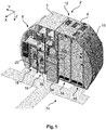
- Fig. 1 shows a modular cabin monument 2, which is to be installed at a rear end of an aircraft cabin, delimited by a pressure bulkhead.
- the cabin monument 2 comprises a first lateral segment module 4 and a second lateral segment module 6, which in each case comprise lateral delimiting surfaces 8 and 10, shaped so as to snugly fit with the corresponding aircraft fuselage walls.
- the two lateral segment modules 4 and 6 are attached to each other in a central region 12 or simply face each other to form an integral monument extending along the whole available width.
- the first lateral segment module 4 is a galley module
- the second lateral segment module 6 is a toilet module having a first toilet compartment 14 with a rather wide bi-fold door and a second toilet compartment 16 having a single, swivable door.
- the first lateral module segment 4 comprises a plurality of trolley parking spaces 18, which are designed for receiving trolleys 20 with different lengths, such as so-called half-size trolleys and full-size trolleys. It is further conceivable that a plurality of trolleys may be arranged one behind the other in a single parking space 18, especially near thecenter region 12 as there is an enlarged extension due to the pressure bulkhead.
- a sidewall 22 is present, which extends along the longitudinal axis of the cabin, to which sidewall 22 a cabin attendant seat 24 is mounted.
- the cabin attendant seat 24 is movable in a lateral direction, i.e. along an y-axis and substantially parallel to a front face of the monument 2. How this is achieved will be explained with reference to further figures further below.
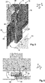
- Fig. 2 shows a parking space 18, in which a trolley 20 is introduced and arrested by locking bolts 26 for preventing the trolley 20 from leaving the parking space 18 caused by the motion of the vehicle.
- a base body 28 Adjacent to the parking space 18 and facing the second lateral segment module 6, a base body 28 is attached to the sidewall 22. It is apparent, that the sidewall 22 extends in an x-direction from a front face 30 of the second lateral module segment 6, leading to a step 32.
- the basic body 28 has an elongate shape and exemplarily a pentagonal cross-sectional surface, wherein the actual cross-section is designed so as to flushly fill the step 32 in that a front face 34 of the basic body 28 is flush with the adjacent front face 36 of the sidewall 22.
- linear movement means 38, 40 and 42 Attached to the front face 34 of the base body 28 are three linear movement means 38, 40 and 42, each having a laterally movable rail 44, a guide 46 for guiding and supporting the respective rail and a flange 48 for attaching the linear movement means 38, 40 and 42 to the front face 34.
- the linear movement means 38 and 40 comprise an integrated arresting means 50 each, which is configured for holding the respective rail 44 in a predetermined discrete position.
- three different positions are defined by providing recesses 52, 54 and 56 in fixed positions relative to the rails 44, into which a correspondingly shaped member of the respective arresting means 50 may be introduced in order to provide for a positive, interlocking connection.
- the positions of the recesses 52, 54 and 56 are responsible for the desired end positions, in which the rails 44 are to be arrested. More details about possible positions will be made hereinafter.
- the base body 28 does not need to be a rigid body. It may be sensible to design the base body 28 as a completely hollow component, which may carry a locking mechanism for engaging and disengaging the arresting means 50 in the respective recesses 52, 54 and 56.
- an upper end face 58 of base body 28 comprises a slit 60, through which a knob 62 extends, which may be moved along the slit 60.
- Appropriate connecting means such as levers and rods, lead to engaging and disengaging the arresting means 50.
- the arresting means 50 comprises a tapered locking body 64 having a protrusion 66 at an end facing the associated rail 44.
- a push rod 68 which is swivably held at an end of the locking body 64 facing away from the rail 44, the locking body 64 may at least be moved in a vertical direction, i.e. towards or away from the rail 44, which equals the z-direction in an aircraft-fixed coordinate system.
- the protrusion 66 may enter the recess 52, 54 or 56 or may be moved out of it. If the locking body 64 is in a lower position, in which the protrusion 66 does not engage any recess 52, 54 and 56, the rail 44 may be moved along the guide 46 in a lateral, i.e. y-direction.
- the flange 48 comprises a set of boreholes 70, which are configured for fastening the linear movement means 38 to the front face 34 of the base body 28 by means of bolts or other fastening elements.
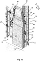
- Fig. 4 shows a cabin attendant seat 24 attached to the rails 44 of the linear movement means 38, 40 and 42 as well as the base body 28 in a partially translucent view, in which the locking mechanism 72 is visible.
- the base body 28 vertically extends substantially to the floor 74 of the cabin, wherein the knob 62 and the slit 60 in the upper face 58 of the base body 28 are situated in a region behind a headrest 76 so as to comprise a suitable vertical position for ergonomic operation.
- Fig. 5 shows the cabin attendant seat 24 as attached to the rails 44 from another perspective. It is clearly apparent that the cabin attendant seat 24 may be moved into a region in front of at least one trolley parking position 18, into a region in front of the first toilet compartment 14 or into a region overlapping the trolley parking position 18 or the first toilet compartment 14. This is further shown in Fig. 6 , which is a top view onto the cabin attendant seat 24 attached to the rails 44 and arrested in a middle position.
- a bi-fold lavatory door to the first toilet compartment 14 may be opened and closed, as it is not completely blocked by the cabin attendant seat 24.
- FIGs. 7 , 8 and 9 An alternative position of the cabin attendant seat 24 is shown in Figs. 7 , 8 and 9 .
- a "trolley-free" position is shown, in which the cabin attendant seat 24 is at its leftmost position from the perspective of a person sitting on the cabin attendant seat 24. Consequently, the cabin attendant seat 24 only extends into a region in front of the first toilet compartment 14 and thus completely blocks the access to it.
- each of the parking positions 18 remains unblocked, which allows the parking positions 18 to be accessible in order to exchange trolleys and other containers in the first segment module 4, for example before or after the passengers are in the cabin.
- a still further position for the cabin attendant seat is shown, which is considered a "crew rest position", in which a cabin crew member may rest on the cabin attendant seat 24.
- a curtain between a receiving section 80 on the base body 28 and a partition wall 82 in a distance to the cabin attendant seat 24 in x-direction, i.e. vertical to the main extension plane of the cabin attendant seat 24.
- the curtain 78 may be rolled out of a container integrated into the base body 28 or out of a container integrated into the partition wall 82.
- the base body does not comprise a completely rectangular cross-section but a triangular cut-out 84 to receive the curtain 78.
- the first toilet module 14 is completely unblocked, while at the same time the crew enjoys a sufficient privacy protection.
- a headset 86 may be installed adjacent to the headrest 76 for allowing a crew member sitting on the cabin attendant seat to communicate with other crew members or for making announcements to the cabin.
- a rail 44 may be connected with an adapter 90, which allows for a connection with a standard cabin attendant seat, i.e. a wall mountable cabin attendant seat.
- a standard cabin attendant seat i.e. a wall mountable cabin attendant seat.
- individual adapters 90 may be used for connection to the rail 44 without requiring to use different rails 44 for considering the vehicle operator's requirements for seats to be used.
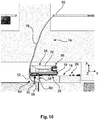
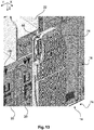
- the guide 46 is clarified as a dovetail guide that allows for a rigid and stable mechanical connection between the rail and the guide 46.
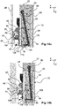
- the mechanism 72 comprises a set of levers arranged for moving the locking body 64 upward and downward.
- the knob 62 is connected to a main lever 92, which extends to a first pivoting point 94, about which the main lever 92 is pivotally coupled. This means that by pulling the knob 62 in the drawing plane of Fig. 14A to the right it rotates with an end opposite to the knob 62 around the first pivoting point 94.
- the first pivoting point 94 is created through a holder 96, which extends from an inner walling surface 98 of the base body 28 into its interior. It is also conceivable that the holder 96 is a part of the flange 48, which extends from the outside into the base body 28.
- Three interconnected levers 100, 102 and 104 constitute a lever chain extending from a second pivoting point 106, which is situated on the main lever 92, to the respective locking body 64.
- the center lever 102 is pivotally supported on a third pivoting point 108, which is located on the flange 48.
- the locking body 64 further is pivotally supported on a fourth pivoting point 110, which is located on or in the guide 46 or flange 48 with an end opposite to the protrusion 66 of the locking body.
- the protrusion 66 engages the recess 54 in the adapter 90 mounted to rail 44 while it is disengaged in Fig. 14b .
- the knob 62 is in a position facing the cabin attendant seat 24.
- the main lever 92 rotates about the first pivoting point 94 and thereby pulls the chain of levers 100, 102 and 104. Consequently, the middle lever 102 rotates about the third pivoting point 108 and thereby pulls the third lever 104 downwardly.
- the protrusion 66 is pulled out of recess 54. Thereby, the positive connection between the locking body 64 and the recess 54 in the adapter 90, are disengaged.
- the positive connection between the locking body 64 and the linear movement means may be disengaged by moving the knob 62 into a position at a greater distance to the cabin attendant seat, moving the cabin attendant seat 24 in a lateral direction through the moving means, releasing the knob 62 and align the cabin attendant seat into one of the predetermined positions, in which the locking body snaps into the respective recess and automatically locks the cabin attendant seat in this position.
- a connecting lever 110 may be extending between two middle levers of two arresting means 50, wherein the connecting lever connects to a pivoting point between levers 100 and 102. Hence, by moving the knob 62, both arresting means 50 are operated.
Landscapes
- Engineering & Computer Science (AREA)
- Aviation & Aerospace Engineering (AREA)
- Seats For Vehicles (AREA)
Claims (13)
- Vorrichtung zum Halten eines Flugbegleitersitzes (24) in einer Kabine eines Fahrzeugs, umfassend:- einen Grundkörper (28), der an einer Wandfläche in der Kabine anbringbar ist,- mindestens ein Halteelement (90) zum Halten eines Flugbegleitersitzes (24),- mindestens ein linear bewegliches Element (38, 40, 42) mit einer Schiene (44) und einer Führung (46) zur Führung der Schiene (44), und- mindestens ein Arretierungselement (50),wobei das mindestens eine linear bewegliches Element (38, 40, 42) an dem Grundkörper befestigt ist (28) und das mindestens eine Halteelement (90) unterstützt,
wobei das mindestens eine linear bewegliches Element (38, 40, 42) zum seitlichen Bewegen des mindestens einen Halteelements (90) zwischen mindestens zwei seitlich beabstandeten diskreten Positionen konfiguriert ist,
wobei das mindestens eine Arretierungselement (50) mit dem mindestens einen linear bewegliches Element (38, 40, 42) gekoppelt ist und zum Arretieren des mindestens einen linear bewegliches Elements (38, 40, 42) in den mindestens zwei diskreten Positionen konfiguriert ist, so dass der Kabinenbegleitersitz (24) benutzbar bleibt,
wobei das mindestens eine Arretierungselement (50) einen Verriegelungskörper (64) aufweist, der mit mindestens einer Ausnehmung (52, 54, 56) in Eingriff bringbar ist, die in einer festen geometrischen Beziehung zu der Schiene (44) angeordnet ist,
wobei sich ein Verriegelungsmechanismus (72) in dem Grundkörper (28) erstreckt und eine Hebelkette (100, 102, 104) aufweist, der mit dem Verriegelungskörper und einem Haupthebel (92) gekoppelt ist, der schwenkbar mit einem ersten Schwenkpunkt (94) gekoppelt ist, wobei durch Bewegen des Haupthebels (92) der Verriegelungskörper (64) und die Ausnehmung (54) außer Eingriff gebracht werden können. - Vorrichtung nach Anspruch 1,
wobei das mindestens eine Halteelement (90) zum Halten eines Flugbegleitersitzes (24) einen Adapter zum mechanischen Verbinden des mindestens einen linear bewegliches Element (38, 40, 42) mit dem Flugbegleitersitz (24) aufweist,
wobei der Adapter an ein gewünschtes spezifisches Modell des Flugbegleitersitzes (24) angepasst ist. - Vorrichtung eines der früheren Ansprüche,
mit einer Vielzahl von Arretierungselementen (50),
wobei das Bedienungselement (62, 92) mit jedem der Arretierungselemente (50) gekoppelt ist. - Vorrichtung nach Anspruch 3,
wobei der Verriegelungsmechanismus so ausgelegt ist, dass er automatisch in eine Verriegelungsposition zurückkehrt, wenn das Bedienelement (62, 92) nicht von einem Bediener gehalten wird. - Vorrichtung nach Anspruch 3 oder 4,
wobei sich das Bedienelement (62, 92) durch eine Begrenzungsfläche (58) des Grundkörpers (28) erstreckt. - Vorrichtung nach einem der vorhergehenden Ansprüche,
ferner mit einem Vorhang (78),
wobei der Vorhang (78) zumindest teilweise an dem Grundkörper (28) anbringbar und so konfiguriert ist, dass er sich in eine Position senkrecht zu einer Hauptverlängerungsebene des Flugbegleitersitzes (24) erstreckt. - Modulares Monument (2) für eine Kabine eines Fahrzeugs,
umfassend:- mindestens ein Monument-Modul (4, 6) mit einer Seitenwand (22),- einen Flugbegleitersitz (24) und- ein Gerät nach einem der Ansprüche 1 bis 6 zum Halten des Flugbegleitersitzes (24) an der Seitenwand (22). - Modulares Monument (2) nach Anspruch 7,
bestehend aus einem ersten seitlichen Monument-Modul (4) und einem zweiten seitlichen Monument-Modul (6),
wobei das erste seitliche Monument-Modul (4) ein Galley-Modul ist und wobei das zweite seitliche Monument-Modul (6) ein Toilettenmodul ist. - Modulares Monument (2) nach Anspruch 8,
wobei das Toilettenmodul (6) ein erstes Toilettenabteil (14) und ein angrenzendes zweites Toilettenabteil (16) umfasst. - Modulares Monument (2) nach Anspruch 9,
wobei das erste Toilettenabteil (14) und das zweite Toilettenabteil (16) eine abnehmbare oder einziehbare Trennwand umschließen und
wobei das erste Toilettenabteil (14) und das zweite Toilettenabteil (16) durch Entfernen oder Zurückziehen der Trennwand zu einem einzigen Toilettenabteil kombinierbar sind. - Modulares Monument (2) nach einem der Ansprüche 9 bis 11,
wobei das Bordküchenmodul (4) Wagenparkpositionen (18) zur Aufnahme von Wagen (20) aufweist. - Modulares Monument (2) nach einem der Ansprüche 9 bis 11,
wobei der Kabinenbegleitersitz (24) in mindestens zwei einer Gruppe von Positionen fixierbar ist, wobei die Gruppe umfasst:- eine trolleyfreie Position, wobei sich der Kabinenbegleitersitz (24) hauptsächlich vor einem Toilettenmodul (4) erstreckt,- eine TTL-Position mit dem Kabinenbegleitersitz (24), der sich im Wesentlichen zu gleichen Teilen vor einem Toilettenmodul und einem Bordküchenmodul (6) erstreckt, und- eine Ruheposition für die Besatzung, wobei sich der Flugbegleitersitz (24) hauptsächlich vor einem Bordküchenmodul (6) erstreckt. - Fahrzeug, das eine Kabine und ein Monument (2) gemäß einem der Ansprüche 8 bis 13 aufweist, die in der Kabine angeordnet sind.
Priority Applications (2)
| Application Number | Priority Date | Filing Date | Title |
|---|---|---|---|
| EP14163550.8A EP2927127B1 (de) | 2014-04-04 | 2014-04-04 | Vorrichtung zum Halten eines Flugbegleitersitzes, Kabinenanordnung in einem Fahrzeug und Fahrzeug mit einer Kabine und einer derartigen Kabinenanordnung |
| US14/672,883 US9573689B2 (en) | 2014-04-04 | 2015-03-30 | Apparatus for holding a cabin attendant seat, cabin arrangement in a vehicle and vehicle having a cabin and such a cabin arrangement |
Applications Claiming Priority (1)
| Application Number | Priority Date | Filing Date | Title |
|---|---|---|---|
| EP14163550.8A EP2927127B1 (de) | 2014-04-04 | 2014-04-04 | Vorrichtung zum Halten eines Flugbegleitersitzes, Kabinenanordnung in einem Fahrzeug und Fahrzeug mit einer Kabine und einer derartigen Kabinenanordnung |
Publications (2)
| Publication Number | Publication Date |
|---|---|
| EP2927127A1 EP2927127A1 (de) | 2015-10-07 |
| EP2927127B1 true EP2927127B1 (de) | 2020-10-14 |
Family
ID=50434096
Family Applications (1)
| Application Number | Title | Priority Date | Filing Date |
|---|---|---|---|
| EP14163550.8A Active EP2927127B1 (de) | 2014-04-04 | 2014-04-04 | Vorrichtung zum Halten eines Flugbegleitersitzes, Kabinenanordnung in einem Fahrzeug und Fahrzeug mit einer Kabine und einer derartigen Kabinenanordnung |
Country Status (2)
| Country | Link |
|---|---|
| US (1) | US9573689B2 (de) |
| EP (1) | EP2927127B1 (de) |
Families Citing this family (10)
| Publication number | Priority date | Publication date | Assignee | Title |
|---|---|---|---|---|
| DE102015102314A1 (de) * | 2015-02-18 | 2016-08-18 | Airbus Operations Gmbh | Anordnung mit vor Stößen geschütztem Klappsitz in einer Fahrzeugkabine |
| US9840332B2 (en) * | 2015-10-15 | 2017-12-12 | The Boeing Company | Deployable door-mounted seat |
| DE102016109722A1 (de) * | 2016-05-25 | 2017-11-30 | Airbus Operations Gmbh | Anordnung zum bedarfsweisen Arretieren eines Servierwagens in einer Kabine eines Transportmittels |
| US11235879B2 (en) * | 2016-07-12 | 2022-02-01 | B/E Aerospace, Inc. | Aircraft service trolley and galley enclosure therefor |
| US10689120B2 (en) * | 2016-08-29 | 2020-06-23 | Textron Innovations, Inc. | Stowable reversible seat |
| US10399677B2 (en) * | 2017-07-05 | 2019-09-03 | Panasonic Avionics Corporation | Cart for moving along a surface and method for moving a cart along a surface |
| US10336221B2 (en) * | 2017-10-18 | 2019-07-02 | Ami Industries, Inc. | Stowable seat with backrest release |
| US10953987B2 (en) * | 2018-07-31 | 2021-03-23 | B/E Aerospace, Inc. | Aircraft interior configuration with flexible use space |
| US11377215B1 (en) * | 2020-01-21 | 2022-07-05 | B/E Aerospace, Inc. | Stowable flight attendant seat system |
| US12559237B2 (en) * | 2023-05-24 | 2026-02-24 | The Boeing Company | Combination monument having lavatory and galley for an internal cabin of an aircraft |
Family Cites Families (7)
| Publication number | Priority date | Publication date | Assignee | Title |
|---|---|---|---|---|
| US5632521A (en) * | 1995-06-30 | 1997-05-27 | Flexibulb Inc. | Mobile seat for use in motorized vehicles |
| WO2011101385A2 (de) * | 2010-02-19 | 2011-08-25 | Airbus Operations Gmbh | Toilettenanordnung für ein verkehrsmittel |
| EP3333077B1 (de) * | 2011-02-18 | 2021-09-29 | Airbus Operations GmbH | Modulares fahrgastzellensegment, fahrgastzelle für ein fahrzeug und fahrzeug mit einer fahrgastzelle |
| US8770659B2 (en) * | 2011-02-04 | 2014-07-08 | Ami Industries, Inc. | Self-stowing jumpseat for aircraft |
| DE102011016031A1 (de) * | 2011-04-04 | 2012-10-04 | Airbus Operations Gmbh | Kabinensegment, Kabine und Fahrzeug mit einer Kabine |
| DE102012014619A1 (de) * | 2012-07-24 | 2014-01-30 | Airbus Operations Gmbh | Gleitender Flugbegleitersitz |
| US9493093B2 (en) * | 2013-12-04 | 2016-11-15 | Oshkosh Corporation | Variable position seat mounting system |
-
2014
- 2014-04-04 EP EP14163550.8A patent/EP2927127B1/de active Active
-
2015
- 2015-03-30 US US14/672,883 patent/US9573689B2/en not_active Expired - Fee Related
Non-Patent Citations (1)
| Title |
|---|
| None * |
Also Published As
| Publication number | Publication date |
|---|---|
| US20150284097A1 (en) | 2015-10-08 |
| EP2927127A1 (de) | 2015-10-07 |
| US9573689B2 (en) | 2017-02-21 |
Similar Documents
| Publication | Publication Date | Title |
|---|---|---|
| EP2927127B1 (de) | Vorrichtung zum Halten eines Flugbegleitersitzes, Kabinenanordnung in einem Fahrzeug und Fahrzeug mit einer Kabine und einer derartigen Kabinenanordnung | |
| EP3333077B1 (de) | Modulares fahrgastzellensegment, fahrgastzelle für ein fahrzeug und fahrzeug mit einer fahrgastzelle | |
| US9010686B2 (en) | Module for an aircraft | |
| EP2851296B1 (de) | Vorrichtung zur Befestigung eines Fahrzeugbegleitersitzes in einer Kabine eines Fahrzeugs, Kabinenanordnung in einem Fahrzeug und Fahrzeug mit mindestens einer Kabinenanordnung | |
| EP3936432A1 (de) | Modulares fahrgastzellensegment, fahrgastzelle für ein fahrzeug und fahrzeug mit einer fahrgastzelle | |
| EP2828155B1 (de) | Adapter zur befestigung eines sitzes in einer fahrzeugkabine, sitz für eine fahrzeugkabine und fahrzeug mit einer solchen kabine und einem solchen sitz | |
| EP2690016A2 (de) | Gleitender Flugbegleitersitz | |
| EP3006343B1 (de) | Bordküchenmodul, Kabinenanordnung und Flugzeug | |
| EP3075650A1 (de) | Grosse selbsttragende monumentanordnung für ein flugzeug und flugzeug mit solch einer monumentanordnung | |
| EP2803577A1 (de) | Modifizierbares Flugzeugmodul | |
| EP3209561B1 (de) | Anordnung mit einer partitionierungsvorrichtung in einer kabine eines fahrzeugs und flugzeug mit einer kabine und solch einer anordnung | |
| EP3248875B1 (de) | Stewardsitz, system mit einem stewardsitz sowie anordnung und flugzeugbereich mit dem system | |
| EP2818412B1 (de) | Installationsverfahren für eine flugzeugtoiletteneinheit und entsprechendes flugzeug | |
| US11673671B2 (en) | Passenger seating arrangement | |
| EP2759447A2 (de) | Passagiersitz, Gepäckstück und Passagiersitz-/Gepäckstücksystem | |
| US20180208317A1 (en) | Space optimized cabin arrangement for a vehicle as well as a passenger cabin having a plurality of seats and such a cabin arrangement | |
| CN107826232B (zh) | 飞机座舱区域、包括该飞机座舱区域的飞机及其操作方法 | |
| EP2778064A1 (de) | Passagierdienste zur Bereitstellung von Transportmitteln | |
| US10556661B2 (en) | Arrangement in a vehicle cabin having a cabin monument with two access openings at two aisles, which form an intersection | |
| US10569880B2 (en) | Arrangement for selectively arresting a serving trolley in a cabin of a transportation system | |
| EP3290340B1 (de) | Seitliche, linear bewegbare vorhangschiene | |
| BR102019001890B1 (pt) | Conjunto de divisória de compartimento, e, método de divisão de compartimento |
Legal Events
| Date | Code | Title | Description |
|---|---|---|---|
| PUAI | Public reference made under article 153(3) epc to a published international application that has entered the european phase |
Free format text: ORIGINAL CODE: 0009012 |
|
| AK | Designated contracting states |
Kind code of ref document: A1 Designated state(s): AL AT BE BG CH CY CZ DE DK EE ES FI FR GB GR HR HU IE IS IT LI LT LU LV MC MK MT NL NO PL PT RO RS SE SI SK SM TR |
|
| AX | Request for extension of the european patent |
Extension state: BA ME |
|
| 17P | Request for examination filed |
Effective date: 20160407 |
|
| RBV | Designated contracting states (corrected) |
Designated state(s): AL AT BE BG CH CY CZ DE DK EE ES FI FR GB GR HR HU IE IS IT LI LT LU LV MC MK MT NL NO PL PT RO RS SE SI SK SM TR |
|
| STAA | Information on the status of an ep patent application or granted ep patent |
Free format text: STATUS: EXAMINATION IS IN PROGRESS |
|
| 17Q | First examination report despatched |
Effective date: 20181127 |
|
| GRAP | Despatch of communication of intention to grant a patent |
Free format text: ORIGINAL CODE: EPIDOSNIGR1 |
|
| STAA | Information on the status of an ep patent application or granted ep patent |
Free format text: STATUS: GRANT OF PATENT IS INTENDED |
|
| INTG | Intention to grant announced |
Effective date: 20200507 |
|
| GRAS | Grant fee paid |
Free format text: ORIGINAL CODE: EPIDOSNIGR3 |
|
| GRAA | (expected) grant |
Free format text: ORIGINAL CODE: 0009210 |
|
| STAA | Information on the status of an ep patent application or granted ep patent |
Free format text: STATUS: THE PATENT HAS BEEN GRANTED |
|
| AK | Designated contracting states |
Kind code of ref document: B1 Designated state(s): AL AT BE BG CH CY CZ DE DK EE ES FI FR GB GR HR HU IE IS IT LI LT LU LV MC MK MT NL NO PL PT RO RS SE SI SK SM TR |
|
| REG | Reference to a national code |
Ref country code: GB Ref legal event code: FG4D |
|
| REG | Reference to a national code |
Ref country code: AT Ref legal event code: REF Ref document number: 1323323 Country of ref document: AT Kind code of ref document: T Effective date: 20201015 Ref country code: CH Ref legal event code: EP |
|
| REG | Reference to a national code |
Ref country code: DE Ref legal event code: R096 Ref document number: 602014071163 Country of ref document: DE |
|
| REG | Reference to a national code |
Ref country code: IE Ref legal event code: FG4D |
|
| REG | Reference to a national code |
Ref country code: AT Ref legal event code: MK05 Ref document number: 1323323 Country of ref document: AT Kind code of ref document: T Effective date: 20201014 |
|
| REG | Reference to a national code |
Ref country code: NL Ref legal event code: MP Effective date: 20201014 |
|
| PG25 | Lapsed in a contracting state [announced via postgrant information from national office to epo] |
Ref country code: RS Free format text: LAPSE BECAUSE OF FAILURE TO SUBMIT A TRANSLATION OF THE DESCRIPTION OR TO PAY THE FEE WITHIN THE PRESCRIBED TIME-LIMIT Effective date: 20201014 Ref country code: FI Free format text: LAPSE BECAUSE OF FAILURE TO SUBMIT A TRANSLATION OF THE DESCRIPTION OR TO PAY THE FEE WITHIN THE PRESCRIBED TIME-LIMIT Effective date: 20201014 Ref country code: NO Free format text: LAPSE BECAUSE OF FAILURE TO SUBMIT A TRANSLATION OF THE DESCRIPTION OR TO PAY THE FEE WITHIN THE PRESCRIBED TIME-LIMIT Effective date: 20210114 Ref country code: NL Free format text: LAPSE BECAUSE OF FAILURE TO SUBMIT A TRANSLATION OF THE DESCRIPTION OR TO PAY THE FEE WITHIN THE PRESCRIBED TIME-LIMIT Effective date: 20201014 Ref country code: PT Free format text: LAPSE BECAUSE OF FAILURE TO SUBMIT A TRANSLATION OF THE DESCRIPTION OR TO PAY THE FEE WITHIN THE PRESCRIBED TIME-LIMIT Effective date: 20210215 Ref country code: GR Free format text: LAPSE BECAUSE OF FAILURE TO SUBMIT A TRANSLATION OF THE DESCRIPTION OR TO PAY THE FEE WITHIN THE PRESCRIBED TIME-LIMIT Effective date: 20210115 |
|
| REG | Reference to a national code |
Ref country code: LT Ref legal event code: MG4D |
|
| PG25 | Lapsed in a contracting state [announced via postgrant information from national office to epo] |
Ref country code: ES Free format text: LAPSE BECAUSE OF FAILURE TO SUBMIT A TRANSLATION OF THE DESCRIPTION OR TO PAY THE FEE WITHIN THE PRESCRIBED TIME-LIMIT Effective date: 20201014 Ref country code: AT Free format text: LAPSE BECAUSE OF FAILURE TO SUBMIT A TRANSLATION OF THE DESCRIPTION OR TO PAY THE FEE WITHIN THE PRESCRIBED TIME-LIMIT Effective date: 20201014 Ref country code: BG Free format text: LAPSE BECAUSE OF FAILURE TO SUBMIT A TRANSLATION OF THE DESCRIPTION OR TO PAY THE FEE WITHIN THE PRESCRIBED TIME-LIMIT Effective date: 20210114 Ref country code: IS Free format text: LAPSE BECAUSE OF FAILURE TO SUBMIT A TRANSLATION OF THE DESCRIPTION OR TO PAY THE FEE WITHIN THE PRESCRIBED TIME-LIMIT Effective date: 20210214 Ref country code: LV Free format text: LAPSE BECAUSE OF FAILURE TO SUBMIT A TRANSLATION OF THE DESCRIPTION OR TO PAY THE FEE WITHIN THE PRESCRIBED TIME-LIMIT Effective date: 20201014 Ref country code: SE Free format text: LAPSE BECAUSE OF FAILURE TO SUBMIT A TRANSLATION OF THE DESCRIPTION OR TO PAY THE FEE WITHIN THE PRESCRIBED TIME-LIMIT Effective date: 20201014 Ref country code: PL Free format text: LAPSE BECAUSE OF FAILURE TO SUBMIT A TRANSLATION OF THE DESCRIPTION OR TO PAY THE FEE WITHIN THE PRESCRIBED TIME-LIMIT Effective date: 20201014 |
|
| PG25 | Lapsed in a contracting state [announced via postgrant information from national office to epo] |
Ref country code: HR Free format text: LAPSE BECAUSE OF FAILURE TO SUBMIT A TRANSLATION OF THE DESCRIPTION OR TO PAY THE FEE WITHIN THE PRESCRIBED TIME-LIMIT Effective date: 20201014 |
|
| REG | Reference to a national code |
Ref country code: DE Ref legal event code: R097 Ref document number: 602014071163 Country of ref document: DE |
|
| PG25 | Lapsed in a contracting state [announced via postgrant information from national office to epo] |
Ref country code: RO Free format text: LAPSE BECAUSE OF FAILURE TO SUBMIT A TRANSLATION OF THE DESCRIPTION OR TO PAY THE FEE WITHIN THE PRESCRIBED TIME-LIMIT Effective date: 20201014 Ref country code: SK Free format text: LAPSE BECAUSE OF FAILURE TO SUBMIT A TRANSLATION OF THE DESCRIPTION OR TO PAY THE FEE WITHIN THE PRESCRIBED TIME-LIMIT Effective date: 20201014 Ref country code: LT Free format text: LAPSE BECAUSE OF FAILURE TO SUBMIT A TRANSLATION OF THE DESCRIPTION OR TO PAY THE FEE WITHIN THE PRESCRIBED TIME-LIMIT Effective date: 20201014 Ref country code: CZ Free format text: LAPSE BECAUSE OF FAILURE TO SUBMIT A TRANSLATION OF THE DESCRIPTION OR TO PAY THE FEE WITHIN THE PRESCRIBED TIME-LIMIT Effective date: 20201014 Ref country code: EE Free format text: LAPSE BECAUSE OF FAILURE TO SUBMIT A TRANSLATION OF THE DESCRIPTION OR TO PAY THE FEE WITHIN THE PRESCRIBED TIME-LIMIT Effective date: 20201014 Ref country code: SM Free format text: LAPSE BECAUSE OF FAILURE TO SUBMIT A TRANSLATION OF THE DESCRIPTION OR TO PAY THE FEE WITHIN THE PRESCRIBED TIME-LIMIT Effective date: 20201014 |
|
| PLBE | No opposition filed within time limit |
Free format text: ORIGINAL CODE: 0009261 |
|
| STAA | Information on the status of an ep patent application or granted ep patent |
Free format text: STATUS: NO OPPOSITION FILED WITHIN TIME LIMIT |
|
| PG25 | Lapsed in a contracting state [announced via postgrant information from national office to epo] |
Ref country code: DK Free format text: LAPSE BECAUSE OF FAILURE TO SUBMIT A TRANSLATION OF THE DESCRIPTION OR TO PAY THE FEE WITHIN THE PRESCRIBED TIME-LIMIT Effective date: 20201014 |
|
| 26N | No opposition filed |
Effective date: 20210715 |
|
| PG25 | Lapsed in a contracting state [announced via postgrant information from national office to epo] |
Ref country code: AL Free format text: LAPSE BECAUSE OF FAILURE TO SUBMIT A TRANSLATION OF THE DESCRIPTION OR TO PAY THE FEE WITHIN THE PRESCRIBED TIME-LIMIT Effective date: 20201014 Ref country code: IT Free format text: LAPSE BECAUSE OF FAILURE TO SUBMIT A TRANSLATION OF THE DESCRIPTION OR TO PAY THE FEE WITHIN THE PRESCRIBED TIME-LIMIT Effective date: 20201014 |
|
| PG25 | Lapsed in a contracting state [announced via postgrant information from national office to epo] |
Ref country code: SI Free format text: LAPSE BECAUSE OF FAILURE TO SUBMIT A TRANSLATION OF THE DESCRIPTION OR TO PAY THE FEE WITHIN THE PRESCRIBED TIME-LIMIT Effective date: 20201014 Ref country code: MC Free format text: LAPSE BECAUSE OF FAILURE TO SUBMIT A TRANSLATION OF THE DESCRIPTION OR TO PAY THE FEE WITHIN THE PRESCRIBED TIME-LIMIT Effective date: 20201014 |
|
| PG25 | Lapsed in a contracting state [announced via postgrant information from national office to epo] |
Ref country code: LU Free format text: LAPSE BECAUSE OF NON-PAYMENT OF DUE FEES Effective date: 20210404 |
|
| REG | Reference to a national code |
Ref country code: BE Ref legal event code: MM Effective date: 20210430 |
|
| PG25 | Lapsed in a contracting state [announced via postgrant information from national office to epo] |
Ref country code: LI Free format text: LAPSE BECAUSE OF NON-PAYMENT OF DUE FEES Effective date: 20210430 Ref country code: CH Free format text: LAPSE BECAUSE OF NON-PAYMENT OF DUE FEES Effective date: 20210430 |
|
| PG25 | Lapsed in a contracting state [announced via postgrant information from national office to epo] |
Ref country code: IE Free format text: LAPSE BECAUSE OF NON-PAYMENT OF DUE FEES Effective date: 20210404 |
|
| PG25 | Lapsed in a contracting state [announced via postgrant information from national office to epo] |
Ref country code: IS Free format text: LAPSE BECAUSE OF FAILURE TO SUBMIT A TRANSLATION OF THE DESCRIPTION OR TO PAY THE FEE WITHIN THE PRESCRIBED TIME-LIMIT Effective date: 20210214 |
|
| PG25 | Lapsed in a contracting state [announced via postgrant information from national office to epo] |
Ref country code: BE Free format text: LAPSE BECAUSE OF NON-PAYMENT OF DUE FEES Effective date: 20210430 |
|
| PG25 | Lapsed in a contracting state [announced via postgrant information from national office to epo] |
Ref country code: HU Free format text: LAPSE BECAUSE OF FAILURE TO SUBMIT A TRANSLATION OF THE DESCRIPTION OR TO PAY THE FEE WITHIN THE PRESCRIBED TIME-LIMIT; INVALID AB INITIO Effective date: 20140404 |
|
| PG25 | Lapsed in a contracting state [announced via postgrant information from national office to epo] |
Ref country code: CY Free format text: LAPSE BECAUSE OF FAILURE TO SUBMIT A TRANSLATION OF THE DESCRIPTION OR TO PAY THE FEE WITHIN THE PRESCRIBED TIME-LIMIT Effective date: 20201014 |
|
| PG25 | Lapsed in a contracting state [announced via postgrant information from national office to epo] |
Ref country code: MK Free format text: LAPSE BECAUSE OF FAILURE TO SUBMIT A TRANSLATION OF THE DESCRIPTION OR TO PAY THE FEE WITHIN THE PRESCRIBED TIME-LIMIT Effective date: 20201014 |
|
| PGFP | Annual fee paid to national office [announced via postgrant information from national office to epo] |
Ref country code: GB Payment date: 20240419 Year of fee payment: 11 |
|
| PG25 | Lapsed in a contracting state [announced via postgrant information from national office to epo] |
Ref country code: MT Free format text: LAPSE BECAUSE OF FAILURE TO SUBMIT A TRANSLATION OF THE DESCRIPTION OR TO PAY THE FEE WITHIN THE PRESCRIBED TIME-LIMIT Effective date: 20201014 |
|
| PGFP | Annual fee paid to national office [announced via postgrant information from national office to epo] |
Ref country code: DE Payment date: 20250422 Year of fee payment: 12 |
|
| PGFP | Annual fee paid to national office [announced via postgrant information from national office to epo] |
Ref country code: FR Payment date: 20250425 Year of fee payment: 12 |
|
| PG25 | Lapsed in a contracting state [announced via postgrant information from national office to epo] |
Ref country code: TR Free format text: LAPSE BECAUSE OF FAILURE TO SUBMIT A TRANSLATION OF THE DESCRIPTION OR TO PAY THE FEE WITHIN THE PRESCRIBED TIME-LIMIT Effective date: 20201014 |
|
| GBPC | Gb: european patent ceased through non-payment of renewal fee |
Effective date: 20250404 |
|
| PG25 | Lapsed in a contracting state [announced via postgrant information from national office to epo] |
Ref country code: GB Free format text: LAPSE BECAUSE OF NON-PAYMENT OF DUE FEES Effective date: 20250404 |