EP2927140B1 - Anlage zur Herstellung von gefüllten Behältern mit Trocknungseinheit - Google Patents
Anlage zur Herstellung von gefüllten Behältern mit Trocknungseinheit Download PDFInfo
- Publication number
- EP2927140B1 EP2927140B1 EP14163277.8A EP14163277A EP2927140B1 EP 2927140 B1 EP2927140 B1 EP 2927140B1 EP 14163277 A EP14163277 A EP 14163277A EP 2927140 B1 EP2927140 B1 EP 2927140B1
- Authority
- EP
- European Patent Office
- Prior art keywords
- relative
- pneumatic
- line according
- containers
- Prior art date
- Legal status (The legal status is an assumption and is not a legal conclusion. Google has not performed a legal analysis and makes no representation as to the accuracy of the status listed.)
- Not-in-force
Links
- 238000001035 drying Methods 0.000 title claims description 22
- 230000007423 decrease Effects 0.000 claims description 4
- 230000002093 peripheral effect Effects 0.000 claims 1
- 238000002372 labelling Methods 0.000 description 9
- 210000003739 neck Anatomy 0.000 description 7
- 238000007664 blowing Methods 0.000 description 2
- 241000272525 Anas platyrhynchos Species 0.000 description 1
- 230000000712 assembly Effects 0.000 description 1
- 238000000429 assembly Methods 0.000 description 1
- 238000012432 intermediate storage Methods 0.000 description 1
- 238000004519 manufacturing process Methods 0.000 description 1
Images



Classifications
-
- F—MECHANICAL ENGINEERING; LIGHTING; HEATING; WEAPONS; BLASTING
- F26—DRYING
- F26B—DRYING SOLID MATERIALS OR OBJECTS BY REMOVING LIQUID THEREFROM
- F26B15/00—Machines or apparatus for drying objects with progressive movement; Machines or apparatus with progressive movement for drying batches of material in compact form
- F26B15/02—Machines or apparatus for drying objects with progressive movement; Machines or apparatus with progressive movement for drying batches of material in compact form with movement in the whole or part of a circle
- F26B15/04—Machines or apparatus for drying objects with progressive movement; Machines or apparatus with progressive movement for drying batches of material in compact form with movement in the whole or part of a circle in a horizontal plane
-
- B—PERFORMING OPERATIONS; TRANSPORTING
- B65—CONVEYING; PACKING; STORING; HANDLING THIN OR FILAMENTARY MATERIAL
- B65C—LABELLING OR TAGGING MACHINES, APPARATUS, OR PROCESSES
- B65C9/00—Details of labelling machines or apparatus
- B65C9/0015—Preparing the labels or articles, e.g. smoothing, removing air bubbles
-
- B—PERFORMING OPERATIONS; TRANSPORTING
- B67—OPENING, CLOSING OR CLEANING BOTTLES, JARS OR SIMILAR CONTAINERS; LIQUID HANDLING
- B67C—CLEANING, FILLING WITH LIQUIDS OR SEMILIQUIDS, OR EMPTYING, OF BOTTLES, JARS, CANS, CASKS, BARRELS, OR SIMILAR CONTAINERS, NOT OTHERWISE PROVIDED FOR; FUNNELS
- B67C7/00—Concurrent cleaning, filling, and closing of bottles; Processes or devices for at least two of these operations
-
- B—PERFORMING OPERATIONS; TRANSPORTING
- B65—CONVEYING; PACKING; STORING; HANDLING THIN OR FILAMENTARY MATERIAL
- B65C—LABELLING OR TAGGING MACHINES, APPARATUS, OR PROCESSES
- B65C9/00—Details of labelling machines or apparatus
- B65C9/0015—Preparing the labels or articles, e.g. smoothing, removing air bubbles
- B65C2009/0059—Preparing the articles
Definitions
- the present invention relates to a conveying line in a plant for producing filled containers, in particular bottles.
- a line for conveying containers according to the preamble of claim 1 is disclosed in GB 1 414 661 .
- a line for conveying containers, in particular bottles is provided according to the claims.
- number 1 indicates, as a whole, a plant for producing filled containers defined, in this particular case, by bottles 2, each of which is made of a PET plastic material and comprises a main body 3 and a neck, respectively end neck 4, which is threaded on the outside.
- the plant 1 comprises, in sequence and in this order, a blowing unit 5 of the known type to blow the bottles 2 starting from relative preforms (not shown); a filling unit 6 to feed a product into the bottles 2; a capping unit 7 to close each bottle 2 with a relative cap 8, which is threaded so as to be screwed onto the relative neck 4; and a labelling unit 9 to label the bottles 2.
- a blowing unit 5 of the known type to blow the bottles 2 starting from relative preforms (not shown)
- a filling unit 6 to feed a product into the bottles 2
- a capping unit 7 to close each bottle 2 with a relative cap 8, which is threaded so as to be screwed onto the relative neck 4
- a labelling unit 9 to label the bottles 2.
- the plant 1 comprises, furthermore, a conveying line 10 to transfer the bottles 2 from the capping unit 7 to the labelling unit 9 along a given path P and in a given feeding direction 11.
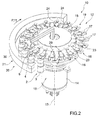
- the line 10 comprises a plurality of feeding drums 12 (only two of them are shown in the figures from 2 to 5), which are mounted so as to continuously rotate around respective substantially vertical rotation axes 13 and are connected to one another in correspondence to relative transfer stations (not shown).
- Each drum 12 comprises a vertical upright 14, which is mounted so as to rotate around the relative axis 13 and supports an upper disc 15, which is coupled to the upright 14 in an angularly fixed manner and is provided with a plurality of pockets 16, which are uniformly distributed around the axis 13 so as to each receive and hold a relative bottle 2.
- Each pocket 16 comprises two jaws 17, which are mobile between a clamping position and a release position, in which they clamp and release, respectively, a relative bottle 2, and are configured to hold the bottle 2 itself in correspondence to the neck 4 under the cap 8.
- Each pocket 16 is fed by the relative drum 12 along a portion of the path P and through an inlet station 18 to let the bottles 2 into the drum 12 and an outlet station 19 to let the bottles 2 out of the drum 12 itself.
- the plant 1 comprises, furthermore, a drying unit 20, which is arranged along the path P between the capping unit 7 and the labelling unit 9 so as to dry the bottles 2.
- the unit 20 comprises, in sequence and in this order, a first drying assembly 21 to dry the bottles 2 in correspondence to the relative necks 4 and caps 8 ( figures 2 and 3 ) and a second drying assembly 22 to dry the bottles 2 in correspondence to the relative bodies 3 ( figures 4 and 5 ).
- the assembly 21 is associated, in particular, with one single drum 12 and comprises, for each pocket 16 of the drum 12 taken into account, a respective drying device 23, which is fixed to the relative disc 15 and is fed around the relative axis 13 and along the path P with the same law of motion as the drum 12 and, therefore, as the pocket 16 itself.
- Each device 23 comprises a pneumatic nozzle 24, which is fixed to the disc 15 above the jaws 17 of the relative pocket 16, substantially has the shape of a duck foot, and is provided with an outlet section that is substantially rectangular and faces the neck 4 and the cap 8 of the relative bottle 2.
- the nozzles 24 are connected to a pneumatic feeding device 25 comprising a pneumatic distributor 26 with a cylindrical shape, which is fixed to a support frame of the drum 12 taken into account, is mounted inside the relative upright 14 coaxial to the relative axis 13, and is engaged in a rotatory manner by the upright 14 itself.
- a pneumatic feeding device 25 comprising a pneumatic distributor 26 with a cylindrical shape, which is fixed to a support frame of the drum 12 taken into account, is mounted inside the relative upright 14 coaxial to the relative axis 13, and is engaged in a rotatory manner by the upright 14 itself.
- the distributor 26 has a manifold 27, which is obtained on an outer surface of the distributor 26, radially faces the upright 14, and extends around the axis 13 from the station 18 to the station 19 in the direction 11.
- the manifold 27 is connected to a source of gas under pressure, in particular air under pressure, by means of a feeding duct 28 coaxial to the axis 13, and is engaged in sequence by a plurality of feeding ducts 29, which are radially obtained through the upright 14 and are each connected to a relative nozzle 24.
- the feeding of air under pressure to the nozzles 24 can be selectively controlled by means of a valve device (not shown), which is mounted in the distributor 26, or by means of a plurality of solenoid valves (not shown), which are each mounted in a respective duct 29.
- the assembly 21 comprises, furthermore, a suction manifold 30, which extends around the axis 13 from the station 18 to the station 19 in the direction 11, is mounted on the opposite side of the nozzles 24 relative to the path P of the bottles 2, and is connected to a known pneumatic sucking device, which is not shown.
- the neck 4 and the cap 8 of each bottle 2 are dried by a substantially laminar flow of air under pressure, which is fed through the relative nozzle 24 and sucked by the manifold 30.
- the manifold 30 is removed and the air under pressure fed through the nozzles 24 is dispersed in the outer environment.
- the assembly 22 is associated, in particular, with at least two drums 12 (only one of them is shown in figures 4 and 5 ) and comprises, for each drum 12, two respective pneumatic manifolds 31, 32, which are mounted on opposite sides of the path P of the bottles 2 and extend around the relative axis 13 from the station 18 to the station 19 in the direction 11.
- the manifolds 31, 32 of each drum 12 extend in respective containing planes that are parallel to one another and perpendicular to the relative axis 13, and are connected to a source of gas under pressure, in particular air under pressure.
- Each manifold 31 is external to the path P, is mounted above the relative manifold 32, and cooperates with a plurality of substantially vertical columns 33, which project downwards from the manifold 31 and have a length that is measured parallel to the axis 13 and increases in the direction 11.
- the columns 33 have respective outlet mouths 34, which are oriented towards the body 3 of the bottles 2 and are arranged at a height from the ground that decreases in the direction 11.
- Each manifold 32 is internal to the path P and cooperates with a plurality of substantially vertical columns 35, which project upwards from the manifold 32 and have a length that is measured parallel to the axis 13 and decreases in the direction 11.
- the columns 35 have respective outlet mouths 36, which are oriented towards the body 3 of the bottles 2 and are arranged at a height from the ground that decreases in the direction 11.
- the mouths 34 can be radially aligned with corresponding mouths 36 or tangentially staggered relative to the mouths 36 themselves.
- the body 3 of each bottle 2 is dried from the top to the bottom, thus causing product remains lying on the outer surface of the body 3 itself to progressively slide downwards.
- the plant 1 leads to advantages that are mainly due to the fact that the introduction of the drying unit 20 between the capping unit 7 and the labelling unit 9 allows the bottles 2 to be dried before they get into the labelling unit 9, thus ensuring a correct labelling of the bottles 2 themselves.
- the configuration of the drying assemblies 21, 22 allows the bottles 2 to be dried while they are being fed on the drums 12 and to be transferred from the capping unit 7 to the labelling unit 9 in a relatively quick fashion and along a relatively short path. Moreover, in this way, possible intermediate storage tanks to store the bottles 2 can be eliminated.
Landscapes
- Engineering & Computer Science (AREA)
- Mechanical Engineering (AREA)
- General Engineering & Computer Science (AREA)
- Filling Of Jars Or Cans And Processes For Cleaning And Sealing Jars (AREA)
Claims (14)
- Anlage zum Befördern von Behältern (2), insbesondere Flaschen, wobei jeder Behälter (2) einen Hauptkörper (3) und einen Endhals (4), der von einer zugehörigen Kappe (8) verschlossen wird, umfasst, wobei die Förderanlage eine Vielzahl von Taschenfördervorrichtungen (12), die in Reihe zueinander angeordnet sind, um die Behälter (2) entlang eines Wegs (P) zu befördern, und jede eine entsprechende Vielzahl von Taschen (16) aufweist, die jeweils dafür ausgelegt sind, einen zugehörigen Behälter (2) aufzunehmen und festzuhalten; und eine Trocknungseinheit (20) umfasst, die entlang des Wegs (P) angeordnet ist, um die Behälter (2) zu trocknen, und für jede Tasche (16) wenigstens einer ersten Taschenfördervorrichtung (12) eine entsprechende Trocknungsvorrichtung (23) umfasst; wobei jede Trocknungsvorrichtung (23) und die zugehörige Tasche (16) in Gleichlauf miteinander entlang des Wegs (P) beweglich sind; und dadurch gekennzeichnet sind, dass jede Tasche (16) ein Greif- und Platzierelement (17) umfasst, das dafür gestaltet ist, den zugehörigen Behälter (2) dem Endhals (4) unter der Kappe (8) entsprechend festzuhalten; wobei jede Trocknungsvorrichtung (23) über dem entsprechenden Greif- und Platzierelement (17) angeordnet ist, um den zugehörigen Behälter (2) der Kappe (8) und dem Endhals (4) entsprechend zu trocknen.
- Förderanlage gemäß Anspruch 1, wobei jede Trocknungsvorrichtung (23) eine pneumatische Düse (24) zum Trocknen wenigstens eines Teils des zugehörigen Behälters (2) mit einem Strom von druckbeaufschlagtem Gas umfasst.
- Förderanlage gemäß einem der vorstehenden Ansprüche, ferner umfassend einen Ansaugverteiler (30), der entlang des Wegs (P) zwischen einem Einlass (18) zum Einlassen der Behälter (2) in die erste Taschenfördervorrichtung (12) und einem Auslass (19) zum Auslassen der Behälter (2) aus der ersten Taschenfördervorrichtung (12) angebracht ist, angeordnet an der gegenüberliegenden Seite der Trocknungsvorrichtungen (23) bezogen auf die Taschen (16) und verbunden mit einer pneumatischen Ansaugvorrichtung.
- Förderanlage gemäß einem der vorstehenden Ansprüche, wobei jede Taschenfördervorrichtung (12) eine Zuführtrommel umfasst, die zum Drehen um eine im Wesentlichen senkrechte Drehachse (13) angebracht ist und ihrerseits eine Vielzahl von Greif- und Platzierelementen (17) für die Behälter (2) umfasst, die entlang eines Umfangsrands der Zuführtrommel selbst angeordnet sind.
- Förderanlage gemäß Anspruch 4, wobei die Trocknungseinheit (20) für jedes Greif- und Platzierelement (17) der ersten Taschenfördervorrichtung (12) eine entsprechende pneumatische Düse (24) umfasst, die an der zugehörigen Zuführtrommel befestigt ist, um den zugehörigen Behälter (2) der Kappe (8) und dem Endhals (4) entsprechend zu trocknen.
- Förderanlage gemäß Anspruch 5, wobei die Trocknungseinheit (20) ferner einen feststehenden pneumatischen Verteiler (26) umfasst, der um die Drehachse (13) zwischen einem Einlass (18) zum Einlassen der Behälter (2) in die erste Taschenfördervorrichtung (12) und einem Auslass (19) zum Auslassen der Behälter (2) aus der ersten Taschenfördervorrichtung (12) verläuft und mit einer Vorrichtung zum Zuführen von druckbeaufschlagtem Gas verbunden ist; wobei jede pneumatische Düse (24) nach der Bewegung der Zuführtrommel der ersten Taschenfördervorrichtung (12) um die Drehachse (13) mit dem feststehenden pneumatischen Verteiler (26) verbunden ist.
- Förderanlage gemäß Anspruch 6, wobei die Trocknungseinheit (20) ferner eine Ventilvorrichtung zum selektiven Steuern des Zuführens von druckbeaufschlagtem Gas unter Druck durch den feststehenden pneumatischen Verteiler (26) umfasst.
- Förderanlage gemäß Anspruch 5 oder 6, wobei die Trocknungseinheit (20) für jede pneumatische Düse (24) ein entsprechendes Magnetventil zum selektiven Steuern des Zuführens von druckbeaufschlagtem Gas durch die pneumatische Düse (24) selbst umfasst.
- Förderanlage gemäß einem der vorstehenden Ansprüche, wobei die Trocknungseinheit (20) ferner für wenigstens eine zweite Taschenfördervorrichtung (12) eine Trocknungsbaugruppe (22) umfasst, die zum Trocknen des Hauptkörpers (3) der Behälter (2) gestaltet ist.
- Förderanlage gemäß Anspruch 9, wobei die Trocknungsbaugruppe (22) wenigstens einen pneumatischen Verteiler (31, 32) umfasst, der entlang des Wegs (P) entsprechend der zweiten Taschenfördervorrichtung (12) verläuft, mit einer Vorrichtung zum Zuführen von druckbeaufschlagtem Gas verbunden ist und eine Vielzahl von Auslässen (34, 36) aufweist, die in Höhen über dem Boden angeordnet sind, die voneinander verschieden sind.
- Förderanlage gemäß Anspruch 10, wobei die Höhe über dem Boden der Auslässe (34, 36) in einer Zufuhrrichtung (11) abnimmt, in der die Behälter (2) entlang des Wegs (P) befördert werden.
- Förderanlage gemäß Anspruch 10 oder 11, wobei die Trocknungsbaugruppe (22) zwei pneumatische Verteiler (31, 32) umfasst, die mit entsprechenden Auslässen (34, 36) versehen sind, die an gegenüberliegenden Seiten des Wegs (P) angebracht sind.
- Förderanlage gemäß Anspruch 12, wobei jeder Auslass (34, 36) eines der pneumatischen Verteiler (31, 32) im Wesentlichen einem entsprechenden Auslass (34, 36) des anderen pneumatischen Verteilers (31, 32) zugewandt ist.
- Förderanlage gemäß Anspruch 12, wobei die Auslässe (34) eines der pneumatischen Verteiler (31, 32) bezogen auf die Auslässe (36) des anderen pneumatischen Verteilers (31, 32) tangential versetzt sind.
Priority Applications (1)
| Application Number | Priority Date | Filing Date | Title |
|---|---|---|---|
| EP14163277.8A EP2927140B1 (de) | 2014-04-02 | 2014-04-02 | Anlage zur Herstellung von gefüllten Behältern mit Trocknungseinheit |
Applications Claiming Priority (1)
| Application Number | Priority Date | Filing Date | Title |
|---|---|---|---|
| EP14163277.8A EP2927140B1 (de) | 2014-04-02 | 2014-04-02 | Anlage zur Herstellung von gefüllten Behältern mit Trocknungseinheit |
Publications (2)
| Publication Number | Publication Date |
|---|---|
| EP2927140A1 EP2927140A1 (de) | 2015-10-07 |
| EP2927140B1 true EP2927140B1 (de) | 2016-11-16 |
Family
ID=50434052
Family Applications (1)
| Application Number | Title | Priority Date | Filing Date |
|---|---|---|---|
| EP14163277.8A Not-in-force EP2927140B1 (de) | 2014-04-02 | 2014-04-02 | Anlage zur Herstellung von gefüllten Behältern mit Trocknungseinheit |
Country Status (1)
| Country | Link |
|---|---|
| EP (1) | EP2927140B1 (de) |
Families Citing this family (3)
| Publication number | Priority date | Publication date | Assignee | Title |
|---|---|---|---|---|
| JP6798693B2 (ja) * | 2016-12-09 | 2020-12-09 | ディ・アイ・エンジニアリング株式会社 | 水滴除去装置 |
| CN107777006B (zh) * | 2017-11-20 | 2023-04-28 | 青岛德隆装备有限公司 | 一种多型化转换瓶型装置 |
| CN109813083B (zh) * | 2019-03-22 | 2020-04-24 | 杭州德飙新能源科技有限公司 | 一种生物质发电用秸秆包烘干装置 |
Family Cites Families (6)
| Publication number | Priority date | Publication date | Assignee | Title |
|---|---|---|---|---|
| DE1025791B (de) * | 1953-03-05 | 1958-03-06 | Jagenberg Werke Ag | Verfahren und Vorrichtung zum Trocknen von Werkstuecken, wie Flaschen od. dgl. |
| FR2272023A1 (en) * | 1974-05-22 | 1975-12-19 | Remy Ets Pierre | Bottleneck drying and wiping mechanism - uses rotary air jets in spiral pattern driving drops downwards for wiping off |
| US5012547A (en) * | 1989-11-27 | 1991-05-07 | Adolph Coors Company | Apparatus for removing fluid particles from containers |
| EP1363096A1 (de) * | 2002-05-16 | 2003-11-19 | Cames snc di Colla G. & Sardi G. | Vorrichtung zum Trocknen der Aussenfläche von Flaschen |
| DE102009052289A1 (de) * | 2009-11-09 | 2011-05-12 | Krones Ag | Vorrichtung und Verfahren zum Etikettieren befüllter Behältnisse |
| JP2013063795A (ja) * | 2011-09-20 | 2013-04-11 | Kirin Techno-System Co Ltd | ガラス壜の水滴除去装置 |
-
2014
- 2014-04-02 EP EP14163277.8A patent/EP2927140B1/de not_active Not-in-force
Non-Patent Citations (1)
| Title |
|---|
| None * |
Also Published As
| Publication number | Publication date |
|---|---|
| EP2927140A1 (de) | 2015-10-07 |
Similar Documents
| Publication | Publication Date | Title |
|---|---|---|
| EP2980010B1 (de) | Anlage zum Abfüllen und Verschliessen von Behältern | |
| US9415989B2 (en) | Apparatus and method for automatically forming and filling containers, in particular water bottles | |
| US20190322514A1 (en) | Apparatus and method for producing plastic bottles | |
| CN106542478B (zh) | 用于生产塑料瓶的设备 | |
| US7404277B2 (en) | Beverage bottling plant for filling bottles with a liquid beverage filling material having an information adding station | |
| US20100018838A1 (en) | System, Apparatus, and Method for Conveying a Plurality of Containers | |
| EP2927140B1 (de) | Anlage zur Herstellung von gefüllten Behältern mit Trocknungseinheit | |
| EP3386905B1 (de) | Maschine zum befüllen von flaschen dosen und ähnliche behälter | |
| CN101506086A (zh) | 处理机 | |
| JP2022151704A (ja) | 液体製品を瓶に無菌で瓶詰めする瓶詰めラインおよび方法 | |
| CN102556430A (zh) | 用于制作容器并使容器对准的装置和方法 | |
| US20160214803A1 (en) | Grippers for thermoplastic containers | |
| US20160052190A1 (en) | Slop-over prevention in form-filling machines | |
| CN110861284A (zh) | 用于制造塑料容器的容器处理设备和容器处理方法 | |
| CN101553354A (zh) | 生产塑料包装容器的方法和设备 | |
| CN101804878B (zh) | 用于为容器贴标签的装置和方法 | |
| US10106390B2 (en) | Labeling machine | |
| US9926180B2 (en) | Capping machine | |
| US20090301840A1 (en) | Apparatus for unscrambling and aligning bulk plastic containers | |
| EP3552978B1 (de) | Anlage und verfahren zum legen von flaschen in entgegengesetzter anordnung | |
| CN105936121B (zh) | 用于制造和灌装容器的机器及其喷嘴组件 | |
| EP3254995A1 (de) | Fördervorrichtung zum transport von artikeln, insbesondere behälter | |
| US11919762B2 (en) | Rotary capsule dispenser for bottling lines | |
| EP2942321A1 (de) | Abfüllanlage und Linie zur Führung von Behältern | |
| US20250026062A1 (en) | Coupling of production machine and stretch blow molding machine via air transport |
Legal Events
| Date | Code | Title | Description |
|---|---|---|---|
| PUAI | Public reference made under article 153(3) epc to a published international application that has entered the european phase |
Free format text: ORIGINAL CODE: 0009012 |
|
| AK | Designated contracting states |
Kind code of ref document: A1 Designated state(s): AL AT BE BG CH CY CZ DE DK EE ES FI FR GB GR HR HU IE IS IT LI LT LU LV MC MK MT NL NO PL PT RO RS SE SI SK SM TR |
|
| AX | Request for extension of the european patent |
Extension state: BA ME |
|
| 17P | Request for examination filed |
Effective date: 20160407 |
|
| RBV | Designated contracting states (corrected) |
Designated state(s): AL AT BE BG CH CY CZ DE DK EE ES FI FR GB GR HR HU IE IS IT LI LT LU LV MC MK MT NL NO PL PT RO RS SE SI SK SM TR |
|
| GRAP | Despatch of communication of intention to grant a patent |
Free format text: ORIGINAL CODE: EPIDOSNIGR1 |
|
| GRAJ | Information related to disapproval of communication of intention to grant by the applicant or resumption of examination proceedings by the epo deleted |
Free format text: ORIGINAL CODE: EPIDOSDIGR1 |
|
| GRAP | Despatch of communication of intention to grant a patent |
Free format text: ORIGINAL CODE: EPIDOSNIGR1 |
|
| GRAJ | Information related to disapproval of communication of intention to grant by the applicant or resumption of examination proceedings by the epo deleted |
Free format text: ORIGINAL CODE: EPIDOSDIGR1 |
|
| GRAP | Despatch of communication of intention to grant a patent |
Free format text: ORIGINAL CODE: EPIDOSNIGR1 |
|
| RIC1 | Information provided on ipc code assigned before grant |
Ipc: B67C 7/00 20060101ALI20160603BHEP Ipc: B65C 9/00 20060101AFI20160603BHEP Ipc: F26B 15/04 20060101ALI20160603BHEP Ipc: B65C 9/06 20060101ALI20160603BHEP |
|
| INTG | Intention to grant announced |
Effective date: 20160623 |
|
| INTG | Intention to grant announced |
Effective date: 20160705 |
|
| GRAS | Grant fee paid |
Free format text: ORIGINAL CODE: EPIDOSNIGR3 |
|
| GRAA | (expected) grant |
Free format text: ORIGINAL CODE: 0009210 |
|
| AK | Designated contracting states |
Kind code of ref document: B1 Designated state(s): AL AT BE BG CH CY CZ DE DK EE ES FI FR GB GR HR HU IE IS IT LI LT LU LV MC MK MT NL NO PL PT RO RS SE SI SK SM TR |
|
| REG | Reference to a national code |
Ref country code: GB Ref legal event code: FG4D |
|
| REG | Reference to a national code |
Ref country code: CH Ref legal event code: EP |
|
| REG | Reference to a national code |
Ref country code: IE Ref legal event code: FG4D |
|
| REG | Reference to a national code |
Ref country code: AT Ref legal event code: REF Ref document number: 845668 Country of ref document: AT Kind code of ref document: T Effective date: 20161215 |
|
| REG | Reference to a national code |
Ref country code: DE Ref legal event code: R096 Ref document number: 602014004818 Country of ref document: DE |
|
| PG25 | Lapsed in a contracting state [announced via postgrant information from national office to epo] |
Ref country code: LV Free format text: LAPSE BECAUSE OF FAILURE TO SUBMIT A TRANSLATION OF THE DESCRIPTION OR TO PAY THE FEE WITHIN THE PRESCRIBED TIME-LIMIT Effective date: 20161116 |
|
| REG | Reference to a national code |
Ref country code: NL Ref legal event code: MP Effective date: 20161116 Ref country code: FR Ref legal event code: PLFP Year of fee payment: 4 |
|
| REG | Reference to a national code |
Ref country code: LT Ref legal event code: MG4D |
|
| REG | Reference to a national code |
Ref country code: AT Ref legal event code: MK05 Ref document number: 845668 Country of ref document: AT Kind code of ref document: T Effective date: 20161116 |
|
| PG25 | Lapsed in a contracting state [announced via postgrant information from national office to epo] |
Ref country code: NL Free format text: LAPSE BECAUSE OF FAILURE TO SUBMIT A TRANSLATION OF THE DESCRIPTION OR TO PAY THE FEE WITHIN THE PRESCRIBED TIME-LIMIT Effective date: 20161116 Ref country code: LT Free format text: LAPSE BECAUSE OF FAILURE TO SUBMIT A TRANSLATION OF THE DESCRIPTION OR TO PAY THE FEE WITHIN THE PRESCRIBED TIME-LIMIT Effective date: 20161116 Ref country code: NO Free format text: LAPSE BECAUSE OF FAILURE TO SUBMIT A TRANSLATION OF THE DESCRIPTION OR TO PAY THE FEE WITHIN THE PRESCRIBED TIME-LIMIT Effective date: 20170216 Ref country code: GR Free format text: LAPSE BECAUSE OF FAILURE TO SUBMIT A TRANSLATION OF THE DESCRIPTION OR TO PAY THE FEE WITHIN THE PRESCRIBED TIME-LIMIT Effective date: 20170217 Ref country code: SE Free format text: LAPSE BECAUSE OF FAILURE TO SUBMIT A TRANSLATION OF THE DESCRIPTION OR TO PAY THE FEE WITHIN THE PRESCRIBED TIME-LIMIT Effective date: 20161116 |
|
| PG25 | Lapsed in a contracting state [announced via postgrant information from national office to epo] |
Ref country code: PL Free format text: LAPSE BECAUSE OF FAILURE TO SUBMIT A TRANSLATION OF THE DESCRIPTION OR TO PAY THE FEE WITHIN THE PRESCRIBED TIME-LIMIT Effective date: 20161116 Ref country code: AT Free format text: LAPSE BECAUSE OF FAILURE TO SUBMIT A TRANSLATION OF THE DESCRIPTION OR TO PAY THE FEE WITHIN THE PRESCRIBED TIME-LIMIT Effective date: 20161116 Ref country code: PT Free format text: LAPSE BECAUSE OF FAILURE TO SUBMIT A TRANSLATION OF THE DESCRIPTION OR TO PAY THE FEE WITHIN THE PRESCRIBED TIME-LIMIT Effective date: 20170316 Ref country code: HR Free format text: LAPSE BECAUSE OF FAILURE TO SUBMIT A TRANSLATION OF THE DESCRIPTION OR TO PAY THE FEE WITHIN THE PRESCRIBED TIME-LIMIT Effective date: 20161116 Ref country code: RS Free format text: LAPSE BECAUSE OF FAILURE TO SUBMIT A TRANSLATION OF THE DESCRIPTION OR TO PAY THE FEE WITHIN THE PRESCRIBED TIME-LIMIT Effective date: 20161116 Ref country code: ES Free format text: LAPSE BECAUSE OF FAILURE TO SUBMIT A TRANSLATION OF THE DESCRIPTION OR TO PAY THE FEE WITHIN THE PRESCRIBED TIME-LIMIT Effective date: 20161116 Ref country code: FI Free format text: LAPSE BECAUSE OF FAILURE TO SUBMIT A TRANSLATION OF THE DESCRIPTION OR TO PAY THE FEE WITHIN THE PRESCRIBED TIME-LIMIT Effective date: 20161116 |
|
| PG25 | Lapsed in a contracting state [announced via postgrant information from national office to epo] |
Ref country code: DK Free format text: LAPSE BECAUSE OF FAILURE TO SUBMIT A TRANSLATION OF THE DESCRIPTION OR TO PAY THE FEE WITHIN THE PRESCRIBED TIME-LIMIT Effective date: 20161116 Ref country code: RO Free format text: LAPSE BECAUSE OF FAILURE TO SUBMIT A TRANSLATION OF THE DESCRIPTION OR TO PAY THE FEE WITHIN THE PRESCRIBED TIME-LIMIT Effective date: 20161116 Ref country code: EE Free format text: LAPSE BECAUSE OF FAILURE TO SUBMIT A TRANSLATION OF THE DESCRIPTION OR TO PAY THE FEE WITHIN THE PRESCRIBED TIME-LIMIT Effective date: 20161116 Ref country code: CZ Free format text: LAPSE BECAUSE OF FAILURE TO SUBMIT A TRANSLATION OF THE DESCRIPTION OR TO PAY THE FEE WITHIN THE PRESCRIBED TIME-LIMIT Effective date: 20161116 Ref country code: SK Free format text: LAPSE BECAUSE OF FAILURE TO SUBMIT A TRANSLATION OF THE DESCRIPTION OR TO PAY THE FEE WITHIN THE PRESCRIBED TIME-LIMIT Effective date: 20161116 |
|
| REG | Reference to a national code |
Ref country code: DE Ref legal event code: R097 Ref document number: 602014004818 Country of ref document: DE |
|
| PG25 | Lapsed in a contracting state [announced via postgrant information from national office to epo] |
Ref country code: SM Free format text: LAPSE BECAUSE OF FAILURE TO SUBMIT A TRANSLATION OF THE DESCRIPTION OR TO PAY THE FEE WITHIN THE PRESCRIBED TIME-LIMIT Effective date: 20161116 Ref country code: BE Free format text: LAPSE BECAUSE OF FAILURE TO SUBMIT A TRANSLATION OF THE DESCRIPTION OR TO PAY THE FEE WITHIN THE PRESCRIBED TIME-LIMIT Effective date: 20161116 Ref country code: BG Free format text: LAPSE BECAUSE OF FAILURE TO SUBMIT A TRANSLATION OF THE DESCRIPTION OR TO PAY THE FEE WITHIN THE PRESCRIBED TIME-LIMIT Effective date: 20170216 |
|
| PLBE | No opposition filed within time limit |
Free format text: ORIGINAL CODE: 0009261 |
|
| STAA | Information on the status of an ep patent application or granted ep patent |
Free format text: STATUS: NO OPPOSITION FILED WITHIN TIME LIMIT |
|
| 26N | No opposition filed |
Effective date: 20170817 |
|
| PG25 | Lapsed in a contracting state [announced via postgrant information from national office to epo] |
Ref country code: SI Free format text: LAPSE BECAUSE OF FAILURE TO SUBMIT A TRANSLATION OF THE DESCRIPTION OR TO PAY THE FEE WITHIN THE PRESCRIBED TIME-LIMIT Effective date: 20161116 |
|
| REG | Reference to a national code |
Ref country code: CH Ref legal event code: PL |
|
| REG | Reference to a national code |
Ref country code: IE Ref legal event code: MM4A |
|
| PG25 | Lapsed in a contracting state [announced via postgrant information from national office to epo] |
Ref country code: MC Free format text: LAPSE BECAUSE OF FAILURE TO SUBMIT A TRANSLATION OF THE DESCRIPTION OR TO PAY THE FEE WITHIN THE PRESCRIBED TIME-LIMIT Effective date: 20161116 |
|
| PG25 | Lapsed in a contracting state [announced via postgrant information from national office to epo] |
Ref country code: CH Free format text: LAPSE BECAUSE OF NON-PAYMENT OF DUE FEES Effective date: 20170430 Ref country code: LU Free format text: LAPSE BECAUSE OF NON-PAYMENT OF DUE FEES Effective date: 20170402 Ref country code: LI Free format text: LAPSE BECAUSE OF NON-PAYMENT OF DUE FEES Effective date: 20170430 |
|
| REG | Reference to a national code |
Ref country code: FR Ref legal event code: PLFP Year of fee payment: 5 |
|
| PG25 | Lapsed in a contracting state [announced via postgrant information from national office to epo] |
Ref country code: IE Free format text: LAPSE BECAUSE OF NON-PAYMENT OF DUE FEES Effective date: 20170402 |
|
| PG25 | Lapsed in a contracting state [announced via postgrant information from national office to epo] |
Ref country code: MT Free format text: LAPSE BECAUSE OF NON-PAYMENT OF DUE FEES Effective date: 20170402 |
|
| GBPC | Gb: european patent ceased through non-payment of renewal fee |
Effective date: 20180402 |
|
| PG25 | Lapsed in a contracting state [announced via postgrant information from national office to epo] |
Ref country code: GB Free format text: LAPSE BECAUSE OF NON-PAYMENT OF DUE FEES Effective date: 20180402 |
|
| PG25 | Lapsed in a contracting state [announced via postgrant information from national office to epo] |
Ref country code: HU Free format text: LAPSE BECAUSE OF FAILURE TO SUBMIT A TRANSLATION OF THE DESCRIPTION OR TO PAY THE FEE WITHIN THE PRESCRIBED TIME-LIMIT; INVALID AB INITIO Effective date: 20140402 |
|
| PG25 | Lapsed in a contracting state [announced via postgrant information from national office to epo] |
Ref country code: CY Free format text: LAPSE BECAUSE OF FAILURE TO SUBMIT A TRANSLATION OF THE DESCRIPTION OR TO PAY THE FEE WITHIN THE PRESCRIBED TIME-LIMIT Effective date: 20161116 |
|
| PG25 | Lapsed in a contracting state [announced via postgrant information from national office to epo] |
Ref country code: MK Free format text: LAPSE BECAUSE OF FAILURE TO SUBMIT A TRANSLATION OF THE DESCRIPTION OR TO PAY THE FEE WITHIN THE PRESCRIBED TIME-LIMIT Effective date: 20161116 |
|
| PG25 | Lapsed in a contracting state [announced via postgrant information from national office to epo] |
Ref country code: TR Free format text: LAPSE BECAUSE OF FAILURE TO SUBMIT A TRANSLATION OF THE DESCRIPTION OR TO PAY THE FEE WITHIN THE PRESCRIBED TIME-LIMIT Effective date: 20161116 |
|
| PG25 | Lapsed in a contracting state [announced via postgrant information from national office to epo] |
Ref country code: AL Free format text: LAPSE BECAUSE OF FAILURE TO SUBMIT A TRANSLATION OF THE DESCRIPTION OR TO PAY THE FEE WITHIN THE PRESCRIBED TIME-LIMIT Effective date: 20161116 Ref country code: IS Free format text: LAPSE BECAUSE OF FAILURE TO SUBMIT A TRANSLATION OF THE DESCRIPTION OR TO PAY THE FEE WITHIN THE PRESCRIBED TIME-LIMIT Effective date: 20170316 |
|
| PGFP | Annual fee paid to national office [announced via postgrant information from national office to epo] |
Ref country code: IT Payment date: 20210323 Year of fee payment: 8 Ref country code: FR Payment date: 20210323 Year of fee payment: 8 |
|
| PGFP | Annual fee paid to national office [announced via postgrant information from national office to epo] |
Ref country code: DE Payment date: 20210323 Year of fee payment: 8 |
|
| REG | Reference to a national code |
Ref country code: DE Ref legal event code: R119 Ref document number: 602014004818 Country of ref document: DE |
|
| PG25 | Lapsed in a contracting state [announced via postgrant information from national office to epo] |
Ref country code: FR Free format text: LAPSE BECAUSE OF NON-PAYMENT OF DUE FEES Effective date: 20220430 Ref country code: DE Free format text: LAPSE BECAUSE OF NON-PAYMENT OF DUE FEES Effective date: 20221103 |
|
| PG25 | Lapsed in a contracting state [announced via postgrant information from national office to epo] |
Ref country code: IT Free format text: LAPSE BECAUSE OF NON-PAYMENT OF DUE FEES Effective date: 20220402 |