EP2927172B1 - Dispositif de bande - Google Patents
Dispositif de bande Download PDFInfo
- Publication number
- EP2927172B1 EP2927172B1 EP14167542.1A EP14167542A EP2927172B1 EP 2927172 B1 EP2927172 B1 EP 2927172B1 EP 14167542 A EP14167542 A EP 14167542A EP 2927172 B1 EP2927172 B1 EP 2927172B1
- Authority
- EP
- European Patent Office
- Prior art keywords
- spool
- tape
- casing
- shaft
- tape device
- Prior art date
- Legal status (The legal status is an assumption and is not a legal conclusion. Google has not performed a legal analysis and makes no representation as to the accuracy of the status listed.)
- Active
Links
Images


Classifications
-
- B—PERFORMING OPERATIONS; TRANSPORTING
- B65—CONVEYING; PACKING; STORING; HANDLING THIN OR FILAMENTARY MATERIAL
- B65H—HANDLING THIN OR FILAMENTARY MATERIAL, e.g. SHEETS, WEBS, CABLES
- B65H37/00—Article or web delivery apparatus incorporating devices for performing specified auxiliary operations
- B65H37/002—Web delivery apparatus, the web serving as support for articles, material or another web
- B65H37/005—Hand-held apparatus
- B65H37/007—Applicators for applying coatings, e.g. correction, colour or adhesive coatings
Definitions
- the present invention relates to a tape device for dispensing correction tape and more particularly, the present invention relates to a device for applying concealing layer from the correction tape onto a surface for covering markings on a document.
- a correction tape device comprises a correction tape coated with opaque concealing layer which will be applied onto the surface for covering the error. By applying pressure on the device, the concealing layer coated on the tape will be adhered to the surface so that the error could be covered and texts could be rewritten on top of the concealing layer.
- Most of the correction tape devices comprise at least one rotatable spool for rolling the correction tape to an applicator tip external of the device, where the concealing layer will be transferred onto the surface by applying pressure.
- the spool with the correction tape therefore needs to be retained in a confined space of a casing to allow for rotation without the spool falling out of the supporting shaft. Furthermore, the casing is required for preventing the external interference such as hands holding the device.
- United States Patent No. US 5942036 discloses a correction tape device which comprises a casing having one opened end and two sides, a main body having a tape guide which can protrude via the opening of the case and a roll mounting portion for placing the spool.
- the device requires an inscribed plate for providing the unused tape and a pinion for collecting the used tape, both of which are rotatably supported via separate shafts.
- the device requires an enclosed casing for holding the inscribed plate and the pinion.
- the main body needs to be properly engaged with the casing to allow functioning of the device. Therefore, when the tape has been used up and needs to be replaced, the casing needs to be detached from the main body for the replacement of a new spool.
- United States Patent No. US 6582514 B1 describes a correction tape device which includes a housing formed of a bottom cover shell and a top cover shell, a tape reel mounted on an upright axle in the housing, the tape reel having an upper reel portion and a lower reel portion, a nose wheel mounted in a peripheral opening of the housing, a tape of correction material wound round the upper reel portion and lower reel portion of the tape reel and extended through the nose wheel.
- the construction of the device requires that the correction tape reel to be enclosed in the top cover shell and the bottom cover shell so that the correction tape reel does not move out of its designated place during its rotation on the shaft. This tightening of the tape reel is not feasible without opening the casing in the event that the tape has been loosened. Further, the replacement of the used tape reel would also require removing the top cover shell.
- United States Patent Publication No. US 20090159217 A1 discloses a correction tape device comprising a casing, a tape holder, a first and second assembly, a tape exporting device, and an applicator head.
- the casing is provided with an accommodating space, an upper covering, a lower covering, and an assembling covering.
- the applicator head can be moved out of the opening of the casing by pushing the poles of the tape holder and thereby forcing the tape holder to move forwards.
- the tape holder would experience a compression elastic force, which would bring the applicator head to the outside the circular opening of the casing.
- the device requires a number of components, including the tape holder, the first and second assembly to be placed within the device. Therefore the device needs to be enclosed by a casing, and opening of the casing is required before the tape can be replaced.
- United States Patent No. US 7036546 B1 describes a label dispenser having one side open for insertion of a label roll.
- the label dispenser is designed for use with rolls of labels or stamps having backing sheets and includes a guide for guiding the backing sheet away once a label or stamp has been removed.
- the label dispenser design does not include a shaft for retaining the label or stamp roll and, as such, rotation of the roll may be difficult if continuous dispensing is required.
- Japanese Patent Publication No. JP 2001287499 A discloses a tape dispenser with a casing formed by a first casing which acts as a base, and a second casing which acts as a tape guide.
- the casing of the tape dispenser is fully enclosed in use, and therefore requires the casing to be opended before replacement of the tape is possible.
- the present invention relates to a tape device for applying a film layer onto a surface, comprising a spool for providing a tape having a film layer, a casing for accommodating the spool, a shaft extended from a portion of the casing for removably retaining the spool, a tape guide mounted on the casing for directing the tape provided from and received by the spool, and an applicator with a tip for guiding the tape onto a surface on which the film layer is applied.
- the casing further comprises an opening, wherein the spool is accessible from external of the casing and is removably attached to the shaft via a fastener from the opening.
- the casing comprising the shaft and the tape guide are fabricated integrally and produced as a single article.
- the shaft of the casing has a free end and comprises a fastener at the free end for removably holding the spool at the shaft and allowing replacement of the spool from the shaft, without having to remove the casing or any covering means thereof.
- the tape device is provided with a connecting member for preventing unintentional contact with external objects interrupting the rotation of the spool in use, said external objects include, for example, the fingers of a user holding the device.
- the spool of the present invention comprises a supply reel for providing the tape coated with concealing layer and a take-up reel for collecting the used tape without concealing layer. Further, the supply reel and the take-up reel are coaxially engaged to each other and rotatably supported on the same shaft.
- the present invention relates to a tape device, more particularly to a correction tape device for applying the film layer onto a surface.
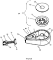
- the correction tape device comprising a spool (10) for providing a tape (11) having film layer, an applicator (20) for guiding the tape (11) onto a surface on which the film layer is applied, and a casing (30) for accommodating the spool (10).
- the film layer is configured as a translucent layer, which is used for the purpose of highlighting an area of the surface.
- the film layer is configured as an opaque layer for concealing an area of the surface. Further, new texts can be written on top of the film layer.
- the film layer in a further embodiment of the invention, is configured with a printed matter for decorative purposes when applied to a surface.
- the film layer may also be configured as an adhesives layer such as a layer of glue for binding other materials to the surface.
- Figure 1 illustrates the tape device with the spool (10) and the applicator (20) assembled into the casing (30).
- the casing (30) is ergonomically shaped for the comfort of holding the device.
- the casing (30) is formed substantially in a teardrop shape such that it has an accommodating space therein for occupying the spool (10).
- the casing (30) further comprises a surface (31), a shaft (32) extended from the surface (31), and a tape guide (34).
- the casing (30) further comprises an opening (39) which is an exposed area of the casing (30), for providing accessibility to the spool (10), so that the spool (10) can be removed from the casing (10).
- the opening (39) of the casing (30) provides the exposed area to the spool (10) and the tape guide (34) so that the spool (10) together with the tape placed around the tape guide (34) is externally accessible for replacement of the spool (10).
- the exposed area of the opening (39) also provides accessibility to rotate the spool (10) to tighten the tape.
- the shaft (32) is a tubular structure extended from the surface (31) for rotatably holding the spool (10) via an annular bore (15) of the spool (10). Therefore, it will be appreciated that the outer diameter of the shaft (32) is substantially same with the inner diameter of the annular bore (15) to allow rotation without excessive movement. It will be apparent that one end of the shaft (32) facing the opening (39) is a free end and is not attached or covered with any other components.
- a fastener preferably but not limited to a clip (33) such that the spool (10) can be detachably held by the shaft (32).
- the clip (33) is biased outward from the shaft (32) such that the clip (33) engages an inner circumference of the annular bore (15) of the spool (10), and keeps the engagement between the spool (10) and the shaft (32) tight.
- the clip (33) is pressed inward to loosen the engagement between the spool (10) and the shaft (32) so that the spool (10) can be slid outward and removed from the shaft (32).
- the fast removal of the spool (10) from the shaft (32) is possible with the casing (30) having the opening (39).
- the clip (33) is integral to the surface (31) and the shaft (32).
- the clip (33) is formed by having a cut-out area extending from the surface (31) to the free end of the shaft (32), for example in the shape of "n".
- the shaft (32) further comprises a plurality of gear teeth at the shaft (32) for providing frictions to the rotation of the spool (10).
- the friction conferred by the plurality of gear teeth is required to cease the rotation of the spool (10) once the user has stopped dragging the correction tape device.
- the plurality of gear teeth is configured in a manner which restricts the rotation of the spool (10) in a single direction. This feature therefore allows adjustment on the spool (10) to tighten the tape and prevents loosening of the tape.
- the shaft (32) is therefore provided at the rounded portion to allow the accommodation of the spool (10) which is also in round shape.
- the pointed portion of the casing (30) is therefore provided with the tape guide (34).
- the tape guide (34) is substantially a triangular configuration mounted on the casing (30) and pointing towards an aperture (36) of the casing (30).
- the function of the tape guide (34) is for directing the tape (11) provided by the spool (10) to the applicator (20) via one side of the tape guide (34) and from the applicator (20) back to the spool (10) via another side of the tape guide (34).
- the tape guide (34) also acts as a structural support for the applicator (20).
- the tape guide (34) is hollow such that the applicator (20) is supported from within the tape guide (34).
- the casing (30) having the opening (39) at one side of the casing (30) does not fully enclose the device.
- the casing (30) is essential in providing a frame for placing the spool (10) and the applicator (20) in a functional position, and at the same time allowing a user to hold the tape device.
- the shape of the casing (30) is rounded for the comfort of the user holding the device.
- the opening (39) of the casing (30) provides accessibility to allow the spool (10) to be changed and adjusted by the user in the event that the tape has been loosened.
- the shaft (32), the tape guide (34), are integral components of the casing (30).
- the casing (30) together with the shaft (32), the clip (33), and the tape guide (34) are preferably fabricated as a single article. This feature of the device is advantageous in simplifying the manufacturing process and reducing the associated cost.
- the casing (30) comprises at least a ridge (38) configuration for the ease of gripping the tape device.
- Said at least a ridge (38) provides friction between the tape device and a user's thumb, such that the tape device is provided with a restriction from slipping off the user's hand while using the tape device.
- the ease of gripping the tape device provides improved manageability of the tape device.
- the applicator (20) is provided exterior to the pointed end of the casing (30) for guiding the tape (11) onto a surface onto which the concealing layer is applied.
- the applicator (20) further comprises an attachment pin (21), a connector (22), a tip (23), a left side wall (24), and a right side wall (25).
- the applicator (20) is fabricated from flexible material, such as but not limited to elastomeric material. The flexibility of the applicator (20) allows movement of the applicator head to a certain extent. This is to ease the use of the device when pressure is applied to slightly bend the applicator (20) and to drag the device over a certain distance.
- the attachment pin (21) of the applicator (20) allows the attachment of the applicator (20) in the tape guide by engaging with a bore (37) of the tape guide (34).
- the connector (22) connects the tip (23) to the attachment pin (21) so that the tip (23) is placed at the aperture (36) of the casing (30) adjacent to the tape guide (34).
- the tip (23) of the applicator (20) provides a planar surface for placing the tape (11) so that the concealing layer can be applied onto a surface of a substrate.
- the tip (23) is provided with the left side wall (24) and the right side wall (25) to prevent the sliding of the tape to the sides.
- the left side wall (24) and the right side wall (25) are both perpendicular to the plane of the tip (23) and are formed in triangular shape with the pointed end facing outward, so as to facilitate the ease of applying pressure at the edge of the tip (23).
- the spool (10) for providing the tape with film layer will now be described.
- the spool (10) further comprises a supply reel (12) for providing tape with concealing layer and a take-up reel (13) for collecting and retaining the used tape.
- the supply reel (12) has a diameter smaller than the diameter of the take-up reel (13), so that loosening of the tape is avoided under normal circumstances.
- both the supply reel (12) and the take-up reel (13) rotates coaxially so that both can be rotated via the same shaft (32) and thereby achieving efficient use of space.
- the rotation of the spool in one direction unwinds the tape with concealing layer towards the applicator (20), and at the same time the used tape is pulled towards the take-up reel (13) and wound onto the take-up reel (13).
- the take-up reel (13) comprises a plurality of friction elements (14) for engaging with the supply reel (12) and allow slipping between the take-up reel (13) and the supply reel (12). This feature is required to prevent the tape from being stuck as the take-up reel (13) diameter is larger than that of the supply reel (12), given that both the supply reel (12) and the take-up reel (13) are rotated at the same rate.
- the supply reel (12) is disposed at the exposed side of the casing (30).
- the supply reel (12) has a round plate on which the decorative graphics or illustrations can be printed for the aesthetic purposes.
- the decorative graphics or illustrations comprises rotational design which has enhanced visual effects when the correction tape device is being used and the spool being rotated.
- the shaft (32) is connected to the tape guide (34) by a connecting member (40) at the opening (39) of the casing (30) for securing the spool (10) from contacting with an external object during rotation of the spool (10).
- the external objects such as fingers of the user holding the device may unintentionally contact the spool (10) when using the device thereby causing interruption to the rotation of the spool (10).
- the connecting member (40) partially covers the spool (10) leaving an exposed area of the spool for accessibility to tighten the tape.
- the connecting member (40) also provides support to the spool (10).
- the connecting member (40) is coupled to the spool (10) to facilitate removal of the spool (10).
- the connecting member (40) is configured to engage the spool (10) so that the removal of connecting member (40) also brings the spool (10) outwards.
- the connecting member (40) is detachably attached to the shaft (32) and the tape guide (34), for example, by having an indent underneath the connecting member (40) for fitting onto the shaft (32) and the tape guide (34).
- the connecting member (40) is configured to facilitate placement of the tape on the tip (23) by having the connecting member (40) connected to the tip (23) forming a subassembly.
Landscapes
- Adhesive Tape Dispensing Devices (AREA)
Claims (16)
- Dispositif à bande comprenant :une bobine (10) pour fournir une bande (11) ayant une couche de film ;un carter (30) pour loger la bobine (10) ;un arbre (32) s'étendant depuis le boîtier (30) pour retenir la bobine (10) de manière amovible ;un guide bande (34) monté sur le boîtier (30) pour diriger la bande (11) fournie et reçue par la bobine (10) ; etun applicateur (20) avec une pointe (23) pour guider la bande (11) sur une surface sur laquelle la couche de film est appliquée ;dans lequel le boîtier (30) est fabriqué d'une seule pièce avec l'arbre (32) et le guide bande (34) ; caractérisé en ce que l'enveloppe (30) comprend en outre une ouverture (39), l'ouverture (39) fournissant une zone exposée à la bobine (10), la bobine (10) étant accessible depuis l'extérieur du boîtier et la bobine (10) est fixée de manière amovible à l'arbre (32) par l'intermédiaire d'une fixation à partir de l'ouverture (39).
- Dispositif à bande selon la revendication 1, dans lequel la couche de film est configurée comme n'importe lequel des éléments suivants ou bien une combinaison d'une couche translucide, d'une couche opaque et d'une couche d'adhésif.
- Dispositif à bande selon la revendication 1, dans lequel la couche de film est configurée avec un imprimé.
- Dispositif à bande selon la revendication 1, dans lequel l'ouverture (39) du boîtier (30) fournit une accessibilité à une zone exposée à la bobine (10) et au guide bande (34) pour serrer la bande ou pour remplacer la bobine (10).
- Dispositif à bande selon la revendication 1, dans lequel la bobine (10) comprend une bobine d'alimentation (12) pour fournir la bande (11) ayant la couche de film et une bobine réceptrice (13) pour récupérer la bande usée.
- Dispositif à bande selon la revendication 5, caractérisé en ce que la bobine réceptrice (13) comprend une pluralité d'éléments de frottement (14) pour engager la bobine d'alimentation (12).
- Dispositif à bande selon la revendication 1, dans lequel la bobine (10) est configurée avec des graphiques décoratifs.
- Dispositif à bande selon la revendication 1, dans lequel l'enveloppe (30) comprend au moins une configuration de nervure (38) pour faciliter la prise du dispositif à bande.
- Dispositif à bande selon la revendication 1, dans lequel l'applicateur (20) est placé sensiblement à l'extérieur du boîtier (30), adjacent au guide bande (34) et est supporté à partir du guide bande (34).
- Dispositif à bande selon la revendication 1, dans lequel l'arbre (32) comprend en outre une pluralité de dents d'engrenage au niveau de l'arbre (32) pour fournir des frottements à la rotation de la bobine (10), dans lequel la pluralité de dents d'engrenage est configurée de manière à limiter la rotation de la bobine (10) pour tourner dans une seule direction.
- Dispositif à bande selon la revendication 1, caractérisé en ce que l'élément de fixation est configuré à une extrémité libre de l'arbre (32) vers l'ouverture (39) du boîtier (30) pour maintenir de manière amovible la bobine (10) au niveau de l'arbre (32) et permettre le remplacement de la bobine (10) de l'arbre (32).
- Dispositif à bande selon la revendication 1, caractérisé en ce que l'élément de fixation est une pince (33) qui est sollicitée vers l'extérieur à partir de l'arbre (32) pour engager la bobine (10).
- Dispositif à bande selon la revendication 1, dans lequel l'arbre (32) est relié au guide bande (34) par un élément de liaison (40) au niveau de l'ouverture (39) du boîtier (30) pour empêcher la bobine (10) de venir en contact avec un objet externe pendant la rotation de la bobine (10) et de fournir un support à la bobine (10).
- Dispositif à bande selon la revendication 13, dans lequel l'élément de connexion (40) est configuré pour faciliter le placement de la bande sur la pointe (23).
- Dispositif à bande selon la revendication 13, dans lequel l'élément de connexion (40) est couplé à la bobine (10) pour faciliter la dépose de la bobine (10).
- Dispositif à bande selon la revendication 13, dans lequel l'élément de connexion (40) recouvre partiellement la bobine (10) en laissant une zone exposée de la bobine (10) pour ménager une accessibilité pour serrer la bande.
Applications Claiming Priority (1)
| Application Number | Priority Date | Filing Date | Title |
|---|---|---|---|
| MYPI2014700832A MY172279A (en) | 2014-04-04 | 2014-04-04 | A tape device |
Publications (2)
| Publication Number | Publication Date |
|---|---|
| EP2927172A1 EP2927172A1 (fr) | 2015-10-07 |
| EP2927172B1 true EP2927172B1 (fr) | 2017-03-01 |
Family
ID=50685770
Family Applications (1)
| Application Number | Title | Priority Date | Filing Date |
|---|---|---|---|
| EP14167542.1A Active EP2927172B1 (fr) | 2014-04-04 | 2014-05-08 | Dispositif de bande |
Country Status (3)
| Country | Link |
|---|---|
| EP (1) | EP2927172B1 (fr) |
| ES (1) | ES2625084T3 (fr) |
| MY (1) | MY172279A (fr) |
Family Cites Families (5)
| Publication number | Priority date | Publication date | Assignee | Title |
|---|---|---|---|---|
| US5942036A (en) | 1998-05-12 | 1999-08-24 | You; Kwang-Ho | Correction tape roller device |
| JP4275839B2 (ja) * | 2000-04-06 | 2009-06-10 | 株式会社トンボ鉛筆 | 塗膜転写具 |
| US6582514B1 (en) | 2002-04-23 | 2003-06-24 | Jacky Yang | Correction tape |
| US7036546B1 (en) * | 2003-01-31 | 2006-05-02 | Ripma Gordon R | Stamp/label dispenser |
| TWM342950U (en) | 2007-12-19 | 2008-10-21 | Leone Penna Co Ltd | Press type correction tape |
-
2014
- 2014-04-04 MY MYPI2014700832A patent/MY172279A/en unknown
- 2014-05-08 ES ES14167542.1T patent/ES2625084T3/es active Active
- 2014-05-08 EP EP14167542.1A patent/EP2927172B1/fr active Active
Non-Patent Citations (1)
| Title |
|---|
| None * |
Also Published As
| Publication number | Publication date |
|---|---|
| MY172279A (en) | 2019-11-20 |
| ES2625084T3 (es) | 2017-07-18 |
| EP2927172A1 (fr) | 2015-10-07 |
Similar Documents
| Publication | Publication Date | Title |
|---|---|---|
| EP2520528B1 (fr) | Dispositif de distribution de ruban adhésif et applicateur de ruban adhésif | |
| US5490898A (en) | Coating film transfer tool | |
| JP2005199631A (ja) | 転写具 | |
| EP1982844A1 (fr) | Outil de transfert de revetement | |
| JP2005193410A (ja) | 転写具 | |
| JP6418821B2 (ja) | 塗布膜転写具 | |
| US6684924B1 (en) | Tape dispenser | |
| JP4352984B2 (ja) | 転写具 | |
| JP4620270B2 (ja) | マーク転写具およびマーク転写テープ | |
| EP2927172B1 (fr) | Dispositif de bande | |
| JP2011245695A (ja) | 塗膜転写具 | |
| EP1183203B1 (fr) | Devidoir pour emballage | |
| US7083348B2 (en) | Combination coating film transfer tool and writing implement | |
| JP4517102B2 (ja) | 筆記具一体型塗膜転写具 | |
| US20150321869A1 (en) | Transfer tool | |
| JP4367221B2 (ja) | 転写具 | |
| JP4774531B2 (ja) | 転写具 | |
| JP4402085B2 (ja) | 腕時計収納ホルダー | |
| US9511618B2 (en) | Writing instrument adapted to dispense note paper | |
| JP3150855U (ja) | 形状保持貼り薬 | |
| KR200489419Y1 (ko) | 수정테이프 | |
| KR100674121B1 (ko) | 펜타입의 수정테잎 | |
| JP2014024203A (ja) | 塗膜転写具 | |
| JP2009083397A (ja) | 塗膜転写具 | |
| CA2551983A1 (fr) | Accessoire pour instrument d'ecriture |
Legal Events
| Date | Code | Title | Description |
|---|---|---|---|
| PUAI | Public reference made under article 153(3) epc to a published international application that has entered the european phase |
Free format text: ORIGINAL CODE: 0009012 |
|
| AK | Designated contracting states |
Kind code of ref document: A1 Designated state(s): AL AT BE BG CH CY CZ DE DK EE ES FI FR GB GR HR HU IE IS IT LI LT LU LV MC MK MT NL NO PL PT RO RS SE SI SK SM TR |
|
| AX | Request for extension of the european patent |
Extension state: BA ME |
|
| 17P | Request for examination filed |
Effective date: 20160125 |
|
| RBV | Designated contracting states (corrected) |
Designated state(s): AL AT BE BG CH CY CZ DE DK EE ES FI FR GB GR HR HU IE IS IT LI LT LU LV MC MK MT NL NO PL PT RO RS SE SI SK SM TR |
|
| GRAP | Despatch of communication of intention to grant a patent |
Free format text: ORIGINAL CODE: EPIDOSNIGR1 |
|
| INTG | Intention to grant announced |
Effective date: 20160905 |
|
| GRAS | Grant fee paid |
Free format text: ORIGINAL CODE: EPIDOSNIGR3 |
|
| GRAA | (expected) grant |
Free format text: ORIGINAL CODE: 0009210 |
|
| AK | Designated contracting states |
Kind code of ref document: B1 Designated state(s): AL AT BE BG CH CY CZ DE DK EE ES FI FR GB GR HR HU IE IS IT LI LT LU LV MC MK MT NL NO PL PT RO RS SE SI SK SM TR |
|
| REG | Reference to a national code |
Ref country code: GB Ref legal event code: FG4D |
|
| REG | Reference to a national code |
Ref country code: CH Ref legal event code: EP Ref country code: AT Ref legal event code: REF Ref document number: 871008 Country of ref document: AT Kind code of ref document: T Effective date: 20170315 |
|
| REG | Reference to a national code |
Ref country code: IE Ref legal event code: FG4D |
|
| REG | Reference to a national code |
Ref country code: DE Ref legal event code: R096 Ref document number: 602014007013 Country of ref document: DE |
|
| REG | Reference to a national code |
Ref country code: NL Ref legal event code: MP Effective date: 20170301 |
|
| REG | Reference to a national code |
Ref country code: LT Ref legal event code: MG4D |
|
| REG | Reference to a national code |
Ref country code: AT Ref legal event code: MK05 Ref document number: 871008 Country of ref document: AT Kind code of ref document: T Effective date: 20170301 |
|
| REG | Reference to a national code |
Ref country code: ES Ref legal event code: FG2A Ref document number: 2625084 Country of ref document: ES Kind code of ref document: T3 Effective date: 20170718 |
|
| PG25 | Lapsed in a contracting state [announced via postgrant information from national office to epo] |
Ref country code: LT Free format text: LAPSE BECAUSE OF FAILURE TO SUBMIT A TRANSLATION OF THE DESCRIPTION OR TO PAY THE FEE WITHIN THE PRESCRIBED TIME-LIMIT Effective date: 20170301 Ref country code: HR Free format text: LAPSE BECAUSE OF FAILURE TO SUBMIT A TRANSLATION OF THE DESCRIPTION OR TO PAY THE FEE WITHIN THE PRESCRIBED TIME-LIMIT Effective date: 20170301 Ref country code: FI Free format text: LAPSE BECAUSE OF FAILURE TO SUBMIT A TRANSLATION OF THE DESCRIPTION OR TO PAY THE FEE WITHIN THE PRESCRIBED TIME-LIMIT Effective date: 20170301 Ref country code: GR Free format text: LAPSE BECAUSE OF FAILURE TO SUBMIT A TRANSLATION OF THE DESCRIPTION OR TO PAY THE FEE WITHIN THE PRESCRIBED TIME-LIMIT Effective date: 20170602 Ref country code: NO Free format text: LAPSE BECAUSE OF FAILURE TO SUBMIT A TRANSLATION OF THE DESCRIPTION OR TO PAY THE FEE WITHIN THE PRESCRIBED TIME-LIMIT Effective date: 20170601 |
|
| PG25 | Lapsed in a contracting state [announced via postgrant information from national office to epo] |
Ref country code: LU Free format text: LAPSE BECAUSE OF NON-PAYMENT OF DUE FEES Effective date: 20170531 Ref country code: SE Free format text: LAPSE BECAUSE OF FAILURE TO SUBMIT A TRANSLATION OF THE DESCRIPTION OR TO PAY THE FEE WITHIN THE PRESCRIBED TIME-LIMIT Effective date: 20170301 Ref country code: LV Free format text: LAPSE BECAUSE OF FAILURE TO SUBMIT A TRANSLATION OF THE DESCRIPTION OR TO PAY THE FEE WITHIN THE PRESCRIBED TIME-LIMIT Effective date: 20170301 Ref country code: RS Free format text: LAPSE BECAUSE OF FAILURE TO SUBMIT A TRANSLATION OF THE DESCRIPTION OR TO PAY THE FEE WITHIN THE PRESCRIBED TIME-LIMIT Effective date: 20170301 Ref country code: AT Free format text: LAPSE BECAUSE OF FAILURE TO SUBMIT A TRANSLATION OF THE DESCRIPTION OR TO PAY THE FEE WITHIN THE PRESCRIBED TIME-LIMIT Effective date: 20170301 Ref country code: BG Free format text: LAPSE BECAUSE OF FAILURE TO SUBMIT A TRANSLATION OF THE DESCRIPTION OR TO PAY THE FEE WITHIN THE PRESCRIBED TIME-LIMIT Effective date: 20170601 |
|
| PG25 | Lapsed in a contracting state [announced via postgrant information from national office to epo] |
Ref country code: NL Free format text: LAPSE BECAUSE OF FAILURE TO SUBMIT A TRANSLATION OF THE DESCRIPTION OR TO PAY THE FEE WITHIN THE PRESCRIBED TIME-LIMIT Effective date: 20170301 |
|
| PG25 | Lapsed in a contracting state [announced via postgrant information from national office to epo] |
Ref country code: SK Free format text: LAPSE BECAUSE OF FAILURE TO SUBMIT A TRANSLATION OF THE DESCRIPTION OR TO PAY THE FEE WITHIN THE PRESCRIBED TIME-LIMIT Effective date: 20170301 Ref country code: EE Free format text: LAPSE BECAUSE OF FAILURE TO SUBMIT A TRANSLATION OF THE DESCRIPTION OR TO PAY THE FEE WITHIN THE PRESCRIBED TIME-LIMIT Effective date: 20170301 Ref country code: RO Free format text: LAPSE BECAUSE OF FAILURE TO SUBMIT A TRANSLATION OF THE DESCRIPTION OR TO PAY THE FEE WITHIN THE PRESCRIBED TIME-LIMIT Effective date: 20170301 Ref country code: CZ Free format text: LAPSE BECAUSE OF FAILURE TO SUBMIT A TRANSLATION OF THE DESCRIPTION OR TO PAY THE FEE WITHIN THE PRESCRIBED TIME-LIMIT Effective date: 20170301 |
|
| PG25 | Lapsed in a contracting state [announced via postgrant information from national office to epo] |
Ref country code: PL Free format text: LAPSE BECAUSE OF FAILURE TO SUBMIT A TRANSLATION OF THE DESCRIPTION OR TO PAY THE FEE WITHIN THE PRESCRIBED TIME-LIMIT Effective date: 20170301 Ref country code: IS Free format text: LAPSE BECAUSE OF FAILURE TO SUBMIT A TRANSLATION OF THE DESCRIPTION OR TO PAY THE FEE WITHIN THE PRESCRIBED TIME-LIMIT Effective date: 20170701 Ref country code: PT Free format text: LAPSE BECAUSE OF FAILURE TO SUBMIT A TRANSLATION OF THE DESCRIPTION OR TO PAY THE FEE WITHIN THE PRESCRIBED TIME-LIMIT Effective date: 20170703 Ref country code: SM Free format text: LAPSE BECAUSE OF FAILURE TO SUBMIT A TRANSLATION OF THE DESCRIPTION OR TO PAY THE FEE WITHIN THE PRESCRIBED TIME-LIMIT Effective date: 20170301 |
|
| REG | Reference to a national code |
Ref country code: DE Ref legal event code: R097 Ref document number: 602014007013 Country of ref document: DE |
|
| REG | Reference to a national code |
Ref country code: CH Ref legal event code: PL |
|
| PLBE | No opposition filed within time limit |
Free format text: ORIGINAL CODE: 0009261 |
|
| STAA | Information on the status of an ep patent application or granted ep patent |
Free format text: STATUS: NO OPPOSITION FILED WITHIN TIME LIMIT |
|
| PG25 | Lapsed in a contracting state [announced via postgrant information from national office to epo] |
Ref country code: DK Free format text: LAPSE BECAUSE OF FAILURE TO SUBMIT A TRANSLATION OF THE DESCRIPTION OR TO PAY THE FEE WITHIN THE PRESCRIBED TIME-LIMIT Effective date: 20170301 Ref country code: MC Free format text: LAPSE BECAUSE OF FAILURE TO SUBMIT A TRANSLATION OF THE DESCRIPTION OR TO PAY THE FEE WITHIN THE PRESCRIBED TIME-LIMIT Effective date: 20170301 |
|
| 26N | No opposition filed |
Effective date: 20171204 |
|
| REG | Reference to a national code |
Ref country code: IE Ref legal event code: MM4A |
|
| PG25 | Lapsed in a contracting state [announced via postgrant information from national office to epo] |
Ref country code: SI Free format text: LAPSE BECAUSE OF FAILURE TO SUBMIT A TRANSLATION OF THE DESCRIPTION OR TO PAY THE FEE WITHIN THE PRESCRIBED TIME-LIMIT Effective date: 20170301 Ref country code: CH Free format text: LAPSE BECAUSE OF NON-PAYMENT OF DUE FEES Effective date: 20170531 Ref country code: LI Free format text: LAPSE BECAUSE OF NON-PAYMENT OF DUE FEES Effective date: 20170531 |
|
| REG | Reference to a national code |
Ref country code: FR Ref legal event code: ST Effective date: 20180131 |
|
| PG25 | Lapsed in a contracting state [announced via postgrant information from national office to epo] |
Ref country code: LU Free format text: LAPSE BECAUSE OF NON-PAYMENT OF DUE FEES Effective date: 20170508 |
|
| REG | Reference to a national code |
Ref country code: BE Ref legal event code: MM Effective date: 20170531 |
|
| PG25 | Lapsed in a contracting state [announced via postgrant information from national office to epo] |
Ref country code: IE Free format text: LAPSE BECAUSE OF NON-PAYMENT OF DUE FEES Effective date: 20170508 |
|
| PG25 | Lapsed in a contracting state [announced via postgrant information from national office to epo] |
Ref country code: FR Free format text: LAPSE BECAUSE OF NON-PAYMENT OF DUE FEES Effective date: 20170531 |
|
| PG25 | Lapsed in a contracting state [announced via postgrant information from national office to epo] |
Ref country code: BE Free format text: LAPSE BECAUSE OF NON-PAYMENT OF DUE FEES Effective date: 20170531 |
|
| PG25 | Lapsed in a contracting state [announced via postgrant information from national office to epo] |
Ref country code: MT Free format text: LAPSE BECAUSE OF NON-PAYMENT OF DUE FEES Effective date: 20170508 |
|
| GBPC | Gb: european patent ceased through non-payment of renewal fee |
Effective date: 20180508 |
|
| PG25 | Lapsed in a contracting state [announced via postgrant information from national office to epo] |
Ref country code: GB Free format text: LAPSE BECAUSE OF NON-PAYMENT OF DUE FEES Effective date: 20180508 |
|
| PG25 | Lapsed in a contracting state [announced via postgrant information from national office to epo] |
Ref country code: HU Free format text: LAPSE BECAUSE OF FAILURE TO SUBMIT A TRANSLATION OF THE DESCRIPTION OR TO PAY THE FEE WITHIN THE PRESCRIBED TIME-LIMIT; INVALID AB INITIO Effective date: 20140508 |
|
| PG25 | Lapsed in a contracting state [announced via postgrant information from national office to epo] |
Ref country code: CY Free format text: LAPSE BECAUSE OF FAILURE TO SUBMIT A TRANSLATION OF THE DESCRIPTION OR TO PAY THE FEE WITHIN THE PRESCRIBED TIME-LIMIT Effective date: 20170301 |
|
| PG25 | Lapsed in a contracting state [announced via postgrant information from national office to epo] |
Ref country code: MK Free format text: LAPSE BECAUSE OF FAILURE TO SUBMIT A TRANSLATION OF THE DESCRIPTION OR TO PAY THE FEE WITHIN THE PRESCRIBED TIME-LIMIT Effective date: 20170301 |
|
| PG25 | Lapsed in a contracting state [announced via postgrant information from national office to epo] |
Ref country code: TR Free format text: LAPSE BECAUSE OF FAILURE TO SUBMIT A TRANSLATION OF THE DESCRIPTION OR TO PAY THE FEE WITHIN THE PRESCRIBED TIME-LIMIT Effective date: 20170301 |
|
| PG25 | Lapsed in a contracting state [announced via postgrant information from national office to epo] |
Ref country code: AL Free format text: LAPSE BECAUSE OF FAILURE TO SUBMIT A TRANSLATION OF THE DESCRIPTION OR TO PAY THE FEE WITHIN THE PRESCRIBED TIME-LIMIT Effective date: 20170301 |
|
| PGFP | Annual fee paid to national office [announced via postgrant information from national office to epo] |
Ref country code: DE Payment date: 20250528 Year of fee payment: 12 |
|
| PGFP | Annual fee paid to national office [announced via postgrant information from national office to epo] |
Ref country code: ES Payment date: 20250606 Year of fee payment: 12 |
|
| PGFP | Annual fee paid to national office [announced via postgrant information from national office to epo] |
Ref country code: IT Payment date: 20250522 Year of fee payment: 12 |