EP2927176A1 - Hebevorrichtung - Google Patents
Hebevorrichtung Download PDFInfo
- Publication number
- EP2927176A1 EP2927176A1 EP15248044.8A EP15248044A EP2927176A1 EP 2927176 A1 EP2927176 A1 EP 2927176A1 EP 15248044 A EP15248044 A EP 15248044A EP 2927176 A1 EP2927176 A1 EP 2927176A1
- Authority
- EP
- European Patent Office
- Prior art keywords
- tensioning
- load engaging
- engaging arrangement
- arrangement
- load
- Prior art date
- Legal status (The legal status is an assumption and is not a legal conclusion. Google has not performed a legal analysis and makes no representation as to the accuracy of the status listed.)
- Withdrawn
Links
- 238000000034 method Methods 0.000 claims description 10
- 230000001965 increasing effect Effects 0.000 claims description 6
- 238000000926 separation method Methods 0.000 claims description 5
- 230000008859 change Effects 0.000 claims description 4
- 230000003068 static effect Effects 0.000 claims description 3
- 230000003247 decreasing effect Effects 0.000 claims description 2
- 208000027418 Wounds and injury Diseases 0.000 description 8
- 238000009434 installation Methods 0.000 description 8
- 238000004804 winding Methods 0.000 description 8
- 238000013459 approach Methods 0.000 description 7
- 239000002184 metal Substances 0.000 description 6
- 230000006378 damage Effects 0.000 description 3
- 230000008439 repair process Effects 0.000 description 3
- 230000008901 benefit Effects 0.000 description 2
- 238000012423 maintenance Methods 0.000 description 2
- 239000000463 material Substances 0.000 description 2
- 239000004033 plastic Substances 0.000 description 2
- 229920003023 plastic Polymers 0.000 description 2
- 239000004753 textile Substances 0.000 description 2
- XGWIJUOSCAQSSV-XHDPSFHLSA-N (S,S)-hexythiazox Chemical compound S([C@H]([C@@H]1C)C=2C=CC(Cl)=CC=2)C(=O)N1C(=O)NC1CCCCC1 XGWIJUOSCAQSSV-XHDPSFHLSA-N 0.000 description 1
- 239000004677 Nylon Substances 0.000 description 1
- 238000004891 communication Methods 0.000 description 1
- 230000008878 coupling Effects 0.000 description 1
- 238000010168 coupling process Methods 0.000 description 1
- 238000005859 coupling reaction Methods 0.000 description 1
- 230000001939 inductive effect Effects 0.000 description 1
- 208000014674 injury Diseases 0.000 description 1
- 238000005259 measurement Methods 0.000 description 1
- 239000007769 metal material Substances 0.000 description 1
- 229920001778 nylon Polymers 0.000 description 1
- 230000021715 photosynthesis, light harvesting Effects 0.000 description 1
- 230000008569 process Effects 0.000 description 1
- 239000000725 suspension Substances 0.000 description 1
- 238000012546 transfer Methods 0.000 description 1
Images


Classifications
-
- B—PERFORMING OPERATIONS; TRANSPORTING
- B66—HOISTING; LIFTING; HAULING
- B66C—CRANES; LOAD-ENGAGING ELEMENTS OR DEVICES FOR CRANES, CAPSTANS, WINCHES, OR TACKLES
- B66C13/00—Other constructional features or details
- B66C13/04—Auxiliary devices for controlling movements of suspended loads, or preventing cable slack
-
- B—PERFORMING OPERATIONS; TRANSPORTING
- B66—HOISTING; LIFTING; HAULING
- B66D—CAPSTANS; WINCHES; TACKLES, e.g. PULLEY BLOCKS; HOISTS
- B66D1/00—Rope, cable, or chain winding mechanisms; Capstans
- B66D1/28—Other constructional details
- B66D1/40—Control devices
- B66D1/48—Control devices automatic
- B66D1/50—Control devices automatic for maintaining predetermined rope, cable, or chain tension, e.g. in ropes or cables for towing craft, in chains for anchors; Warping or mooring winch-cable tension control
Definitions
- the present invention relates to hoist apparatus comprising a load engaging arrangement, such as a lifting hook, and a method therefor.
- the present invention also relates to a crane comprising such hoist apparatus.
- the erection of the like of a wind turbine or removal of parts of a wind turbine during repair or decommissioning operations is normally accomplished with the aid of a mobile crane and typically with a single arm mobile crane.
- Parts of a wind turbine being installed or removed such as sections of tower and the nacelle, are attached to the hook block of the crane before being raised to the requisite height and moved into position for installation or detached and lowered to the ground.
- the hook block of the crane is light compared with when it is laden.
- wind turbine parts are normally light at 150 to 250 kg compared with other loads. As much as 500 m of hoist rope may be wound in as the hook block is raised prior to removal of a wind turbine part or during lifting of a wind turbine part from the ground.
- the present invention has been devised in the light of the inventor's appreciation of the shortcomings of the above mentioned approaches to addressing load jarring. It is therefore an object for the present invention to provide hoist apparatus comprising a load engaging arrangement, such as a lifting hook, the hoist apparatus being configured to reduce the likelihood of a load being jarred by sudden movement of rope wound on a hoist drum of the hoist apparatus.
- a load engaging arrangement such as a lifting hook
- hoist apparatus comprising:
- a load engaging arrangement comprised in hoist apparatus is attached to a load such as wind turbine lifting equipment. Operation of the hoist apparatus applies a lifting force to the load engaging arrangement so as to support the load engaging arrangement and either lift or lower the load engaging arrangement.
- the force applied by the hoist apparatus to the load engaging arrangement may be a supporting force.
- Tensioning apparatus comprised in the hoist apparatus is mechanically coupled to the load engaging arrangement. The tensioning apparatus is operative to selectively apply a tensioning force to the load engaging arrangement, the tensioning force being oppositely directed to the lifting force. The tensioning apparatus may be operative to apply the tensioning force as the load engaging arrangement is being at least one of lifted and lowered.
- the tensioning apparatus may be operative to apply the tensioning force as the load engaging arrangement is being lifted with a light load, such as a wind turbine part, which may be liable to give rise, for example, to insufficiently tight winding of rope wound on a hoist drum of the hoist apparatus.
- the present invention may be applied to particular advantage by applying the tensioning force as the load engaging arrangement is being lifted without a load to a height where the load engaging arrangement is attached to a load prior to lowering the load, for example, to the ground.
- the tensioning apparatus may be operative to cease to apply the tensioning force when the load engaging arrangement is not being lifted or lowered.
- the tensioning apparatus may be operative to cease to apply the tensioning force when the load engaging arrangement is at a requisite height for attachment or detachment of the load. More specifically the tensioning apparatus may be operative to cease to apply the tensioning force when the load engaging arrangement and perhaps also the load is raised above the ground and when the load engaging arrangement is not being moved upwards or downwards.
- Application of the tensioning force to the load engaging arrangement may increase the level of tension on at least one rope of the hoist apparatus whereby the at least one rope may be more tightly wound on a storage arrangement such as a hoist spool or drum of the hoist apparatus as the load engaging arrangement is lifted.
- the tensioning apparatus may be configured to change the applied tensioning force.
- the present invention may be advantageous in particular prior to attachment of a load such as during a decommissioning operation. This is because the load engaging arrangement is raised under light loading conditions and is therefore liable to slacker winding of the rope of the hoist apparatus on the storage arrangement before being lowered in a laden condition when jarring may be liable to occur.
- the tensioning apparatus may be configured to apply the tensioning force from a location spaced apart from the load engaging arrangement.
- the tensioning apparatus may be spaced apart from the load engaging arrangement.
- the hoist apparatus may therefore further comprise at least one tensioning member which is mechanically coupled at a first location to the load engaging arrangement and is mechanically coupled to the tensioning apparatus at a second location which is spaced apart from the first location.
- the at least one tensioning member may be operative to couple the tensioning force to the load engaging arrangement.
- the hoist apparatus may comprise two tensioning members which are each mechanically coupled to the load engaging arrangement at spaced apart locations on the load engaging arrangement.
- the two tensioning members may be mechanically coupled, for example by way of sheaves, to the load engaging arrangement at respective locations on opposite sides of the load engaging arrangement. Coupling of the two tensioning members to the load engaging arrangement in this fashion may provide unobstructed space underneath the load engaging arrangement.
- the hoist apparatus may be configured such that the tensioning apparatus is static. Having static tensioning apparatus may reduce the extent to which the load engaging arrangement swings when being raised to thereby provide for ease of proper winding of the rope on the hoist drum. More specifically the tensioning apparatus may be located at or near the ground. A separation between the tensioning apparatus and the load engaging arrangement may thus increase as the load engaging arrangement is lifted.
- the hoist apparatus may therefore be configured to increase a length of the tensioning member, for example, as the load engaging arrangement is lifted.
- the tensioning apparatus may be configured to maintain a desired tensioning force as the length of the tensioning member is increased or decreased.
- the tensioning member may comprise a pliable, elongate member and more specifically a rope, such as a wire rope.
- the tensioning apparatus may be configured to pay out the pliable, elongate member as the load engaging arrangement is lifted to thereby increase the length of tensioning member.
- the tensioning apparatus may comprise a tensioning member dispenser apparatus which is configured to store the pliable, elongate member and is operative to pay out the pliable, elongate member.
- the tensioning member dispenser apparatus may comprise a tensioning member storage apparatus.
- the tensioning member storage apparatus may comprise a spool on which the tensioning member is wound.
- the tensioning member dispenser apparatus may further comprise an actuator, such as a motor, which is operative to drive the tensioning member storage apparatus, for example, during storage of the tensioning member on the tensioning member storage apparatus.
- an actuator such as a motor
- the actuator is inoperative and the hoist apparatus otherwise configured such that resistance is presented to the tensioning member being drawn from the tensioning member storage apparatus.
- the tensioning member storage apparatus may further comprise a brake which is operative to present resistance to the tensioning member being drawn from the tensioning member storage apparatus.
- the tensioning member storage apparatus may comprise at least one motor which is operative to present resistance to the tensioning member being drawn from the tensioning member storage apparatus.
- the at least one motor may be otherwise operative to wind the tensioning member onto the tensioning member storage apparatus, such as after use of the tensioning member.
- the hoist apparatus may be configured such that an end of the tensioning member other than an end at the tensioning member dispenser apparatus is fixed at a location other than the load engaging arrangement. Nevertheless the tensioning member may be mechanically coupled to the load engaging arrangement between the two ends to thereby apply the tensioning force to the load engaging arrangement. More specifically the tensioning member may be mechanically coupled to the load engaging arrangement so as to provide for movement of the tensioning member relative to the load engaging arrangement. Such relative movement may take place as the load engaging arrangement is lifted by the hoist apparatus.
- the load engaging arrangement may comprise a sheave which receives the tensioning member and provides for movement of the tensioning member relative to the load engaging arrangement. The tensioning member may therefore extend from the tensioning member dispenser apparatus up to the sheave comprised in the load engaging arrangement and then on to a location where the tensioning member is fixed.
- the tensioning apparatus may be configured to maintain a desired tensioning force as the length of the tensioning member is increased. More specifically the tensioning apparatus may be configured to maintain the desired tensioning force at the location where the tensioning member is fixed, i.e. at a location other than the location of the tensioning member dispenser apparatus.
- the tensioning apparatus may comprise a tensioning arrangement to which the tensioning member is fixed and which is operative to provide a tensioning force in the tensioning member.
- the tensioning arrangement may be configured to change a tension in the tensioning member.
- the tensioning force may be changed to provide for the application of a desired tensioning force to the load engaging arrangement.
- the tensioning arrangement may be configured to move the fixed end of the tensioning member to change a separation between the fixed end of the tensioning member and the load engaging arrangement.
- the tensioning arrangement may be configured to reduce a separation between the fixed end of the tensioning member and the load engaging arrangement to thereby reduce the tensioning force; and to increase a separation between the fixed end of the tensioning member and the load engaging arrangement to thereby increase the tensioning force.
- the tensioning arrangement may comprise a linear motor which is operative to move the fixed end of the tensioning member relative to the load engaging arrangement. More specifically the linear motor may comprise a hydraulic cylinder.
- the tensioning arrangement may further comprise a force transducer such as a load cell which is operative to measure the tensioning force.
- the force transducer may be comprised in a main conduit, for example from a hydraulic accumulator, to the hydraulic cylinder.
- the hoist apparatus may be configured to control the tensioning arrangement with regards to the tensioning force in dependence on an output from the force transducer.
- the hoist apparatus may therefore comprise control apparatus which is operative to receive an output from the force transducer.
- the control apparatus may be further operative to provide a signal to the tensioning arrangement to, for example, provide for control of the linear motor.
- the control apparatus may store a predetermined value, e.g. a set-point, corresponding to a predetermined tensioning force.
- the predetermined tensioning force may be stored in dependence on operation by a user of the hoist apparatus.
- the predetermined value may be entered by the user by way of a user control such as a control panel.
- the load engaging arrangement may be lifted by the hoist apparatus until the tensioning force as measured by the force transducer reaches a desired level and a user may thereupon operate the control apparatus to store the measured value as the predetermined value.
- a pressure may be changed within the hydraulic cylinder to move the fixed end of the tensioning member and the load engaging arrangement. More specifically a pressure may be reduced within the hydraulic cylinder to provide for a movement of the fixed end of the tensioning member towards the load engaging arrangement.
- the hydraulic cylinder may comprise a release valve which is operable to reduce the pressure within the hydraulic cylinder.
- the release valve may be operated in dependence on a signal provided by the control apparatus. When, for example, the tensioning force as measured by the force transducer exceeds a predetermined value the control apparatus may be operative to actuate the valve whereby pressure is released from the hydraulic cylinder.
- a pressure may be increased within the hydraulic cylinder to provide for a movement of the fixed end of the tensioning member away from the load engaging arrangement.
- the tensioning arrangement may comprise a hydraulic accumulator and an accumulator valve which is operable to release pressure from the hydraulic accumulator to the hydraulic cylinder.
- the accumulator valve may be operated in dependence on a signal provided by the control apparatus. When, for example, the tensioning force as measured by the force transducer is below a predetermined value the control apparatus may be operative to actuate the accumulator valve whereby pressure in the hydraulic cylinder is increased.
- the tensioning arrangement may further comprise an electric motor which is operative to charge the hydraulic accumulator.
- the tensioning apparatus may be operative to release the tensioning force when the load engaging arrangement is at the installation height.
- the tensioning force may be released to at least a certain extent by operation of the tensioning arrangement to move the fixed end of the tensioning member towards the load engaging arrangement.
- the tensioning force may be released by lowering the load engaging arrangement. Thereafter the fixed end of the tensioning member may be released from the tensioning arrangement.
- the tensioning arrangement may therefore comprise a releasable fastener which is operative to releasably fasten the tensioning member to the tensioning arrangement.
- the releasable fastener may be manually operable.
- the present inventor has appreciated that after release of the tensioning member from the tensioning arrangement, safe removal of the tensioning member from the load engaging arrangement presents some difficulty. For example winding the tensioning member back onto the tensioning member dispenser apparatus is a normally safe operation until the now released end of the tensioning member reaches the load engaging arrangement.
- the tensioning member has disengaged from the load engaging arrangement the falling tensioning member is liable to cause damage or injury and in particular where the tensioning member is heavy such as is often the case when the tensioning member is a wire rope.
- the present inventor has devised a configuration which addresses the problem.
- the hoist apparatus may further comprise an elongate member.
- the elongate member may be lighter, for example per unit length, than the tensioning member. More specifically the elongate member may be lighter by a factor or at least two, four, six, eight, ten, fifteen or twenty than the tensioning member.
- the elongate member may be less hard than the tensioning member. More specifically the elongate member may be formed from non-metallic material such as a textile or plastics material.
- the elongate member may be attached towards the end of the tensioning member present at the tensioning arrangement. Attachment of the elongate member may be achieved manually, for example by an operator of the hoist apparatus. The hoist apparatus may then be operative to draw the tensioning member from the load engaging arrangement.
- the tensioning member may be movably coupled to the load engaging arrangement, for example by way of a sheave. Drawing of the tensioning member from the load engaging arrangement may therefore draw the formerly fixed end of the tensioning member with the elongate member attached towards the load engaging arrangement. When the tensioning member passes the load engaging arrangement the tensioning member may be supported in the air by the attached elongate member and then progressively lowered to the ground. The elongate member may therefore provide for safer lowering of the tensioning member to the ground.
- the elongate member When the tensioning member reaches the ground the elongate member may be detached from the tensioning member. Detachment of the elongate member may be achieved manually, for example by an operator of the hoist apparatus. When the elongate member has been detached the hoist apparatus may be operative to draw in the elongate member.
- the hoist apparatus may be configured to store the drawn in elongate member.
- the hoist apparatus may comprise an elongate member spool or drum which is operative to store the elongate member. The elongate member spool may be operative to dispense the elongate member when the tensioning member is being drawn from the load engaging arrangement.
- the elongate member spool may be operative to wind the elongate member thereon when the elongate member is being stored.
- the hoist apparatus may therefore comprise a motor, such as an electric motor, which is operative to actuate the elongate member spool to provide for winding of the elongate member thereon.
- the hoist apparatus may therefore comprise a biasing arrangement which is operative to provide for tension in the elongate member when in use.
- the biasing arrangement may comprise at least one spring which is operative to provide a spring bias.
- the biasing arrangement may comprise a biasing sheave with which the elongate member mechanically couples and the hoist arrangement may be configured such that the biasing arrangement applies a bias to the biasing sheave to thereby provide tension in the elongate member.
- the biasing arrangement may be configured to provide for movement of the elongate member relative the elongate member dispenser in a direction generally and perhaps substantially orthogonal to a direction in which the elongate member is drawn from or stored on the elongate member dispenser. More specifically and where the elongate member dispenser comprises an elongate member spool, the biasing arrangement may be configured to provide for movement of the elongate member along the elongate member spool. Where the biasing arrangement comprises a biasing sheave, the biasing arrangement may further comprise a member which is mechanically coupled with the biasing sheave so as to provide for movement of the sheave relative to the member.
- a crane comprising hoist apparatus according to the first aspect of the present invention.
- the crane may be fixed or mobile although the present invention finds particular application with mobile cranes which are operative to lower parts of wind turbines. With regards to load capacity, the crane requirements range from 350 to 1200 tonnes.
- the crane may be a telescopic crane and telescoping parts of the crane may be extended and contracted by, for example, hydraulic power. Alternatively or in addition the crane may be a single arm crane. Further embodiments of the second aspect of the present invention may comprise one or more features of the first aspect of the present invention.
- a third aspect of the present invention there is provided a method of at least one of lifting and lowering a load, the method comprising:
- the tensioning apparatus may comprise at least one tensioning member which is removably coupled to the load engaging arrangement. Furthermore and when the load engaging arrangement is at installation or removal height, a fixed end of the at least one tensioning member may be detached from a tensioning arrangement.
- the method may further comprise attaching at least one elongate member, which may be of a form as described above, towards the fixed end of a respective at least one tensioning member.
- the method may further comprise detaching the at least one elongate member from the at least one tensioning member.
- Further embodiments of the third aspect of the present invention may comprise one or more features of the first or second aspect of the present invention.
- hoist apparatus comprising: a load engaging arrangement, such as a lifting hook, which is configured to hold and at least one of lift and lower a load upon application of a lifting force by the hoist apparatus to the load engaging arrangement; and tensioning apparatus mechanically coupled to the load engaging arrangement, the tensioning apparatus being operative to apply a tensioning force to the load engaging arrangement, the tensioning force being oppositely directed to the lifting force.
- a load engaging arrangement such as a lifting hook
- FIG. 1 A view of a crane 10 and hoist apparatus 12 according to the present invention is shown in Figure 1 .
- the crane 10 is single arm mobile crane and has a telescopic jib 14 and is of a load capacity in the range of 350 to 1200 tonnes.
- the two arrows indicate the telescopic movement of the jib 14 and elevation and lowering of the jib 14.
- the crane 10 is being used to support and lower parts of a wind turbine during repair, maintenance or decommissioning of the wind turbine.
- the crane 10 comprises hoist apparatus which comprises normal components of hoist apparatus including a lifting hook arrangement 16 (which constitutes a load engaging arrangement).
- the hoist apparatus 12 further comprises tensioning apparatus 18, which is supported on the ground 20.
- the hoist apparatus comprises two tensioning members 22 which extend between the tensioning apparatus 18 and the lifting hook arrangement 16.
- the tensioning apparatus 18 is operative to apply a tensioning force to the lifting hook arrangement 16 by way of the two tensioning members 22.
- the hoist apparatus is operative to apply a lifting force which causes the lifting hook arrangement 16 to be raised from the ground. The lifting force is therefore upwardly directed.
- the tensioning force is directed towards the ground and is thus oppositely directed to the lifting force whereby the lifting hook arrangement 16 is under tension from above and below.
- Providing downwardly directed tension may provide for tighter winding of wire rope of the hoist apparatus on a hoist drum (not shown) of the crane 10 as the lifting hook arrangement 16 is raised to working height prior to removal of a part from the like of a wind turbine during a repair, maintenance or decommissioning operation.
- the tighter winding of the wire rope on the crane's hoist drum reduces the likelihood of the wire rope slipping and fouling on the hoist drum and thereby causing undesirable jarring of the wind turbine part.
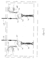
- the tensioning apparatus 30 is of conventional form with the exception of the addition of two sheaves 32. One of the sheaves 32 is attached to one side of the lifting hook arrangement 16 so as to freely rotate and the other of the sheaves 32 is attached to the other side of the lifting hook arrangement 16 so as to freely rotate.
- the tensioning apparatus 30 comprises first 34 and second 36 tensioning member spools. A length of tensioning member is wound on each of the tensioning member spools 34, 36.
- the tensioning member is wire rope such as 26mm non-rotating wire rope from Cesar Limited.
- a first length of tensioning member 38 is drawn up from the first tensioning member spool 34 and away from the ground and fed up to the sheave 32 on the same side of the lifting hook arrangement 16 as the first tensioning member spool 34.
- the end of the first length of tensioning member 38 is fed over the sheave 32 such that the sheave 32 provides for movement of the first length of tensioning member 38 and the lifting hook arrangement 16 in relation to each other.
- the end of the first length of tensioning member 38 is then drawn back towards the ground and attached at its end towards a first corner 40 of a vertically disposed triangle shaped piece of sheet metal.
- the end of the tensioning member 38 is attached at the first corner 40 by way of a releasable fastener of well-known form and function.
- a second length of tensioning member 42 is drawn from the second tensioning member spool 36 and fed up to the sheave 32 on the same side of the lifting hook arrangement 16 as the second tensioning member spool 36.
- the end of second length of tensioning member 42 is fed over the sheave 32 such that the sheave 32 provides for movement of the second length of tensioning member 42 and the lifting hook arrangement 16 in relation to each other.
- the end of the second length of tensioning member 42 is then drawn back towards the ground and attached at its end towards a second corner 44 of the vertically disposed triangle shaped piece of sheet metal.
- the second corner 44 is at the same height above the ground as the first corner 40.
- the end of the second tensioning member 42 is attached at the second corner 44 by way of a releasable fastener of well-known form and function. The thus described configuration provides for application of the tensioning force to the lifting hook arrangement 16.
- the tensioning apparatus 30 further comprises a linear motor in the form of a hydraulic cylinder 46.
- a distal end of a piston 48 of the hydraulic cylinder 46 is attached to a third corner 50 of the triangle shaped piece of sheet metal, the third corner 50 being disposed closer to the ground than the first and second corners 40, 44.
- the tensioning apparatus 30 further comprises a hydraulic accumulator (not shown), an accumulator valve (not shown), an electric motor (not shown) and control apparatus (not shown).
- the hydraulic accumulator which is of known form and function, is charged on a continuous basis by the electric motor.
- the hydraulic accumulator is fluidic communication with the hydraulic cylinder by way of the accumulator valve which opens and closes under control of the control apparatus.
- the tensioning apparatus 30 yet further comprises a release valve (not shown) which is operable to reduce the pressure within the hydraulic cylinder and to thereby allow the piston 48 to rise.
- the release valve is operated in dependence on a signal from the control apparatus.
- the tensioning apparatus 30 comprises a load cell (not shown) which is comprised in the main conduit between the hydraulic accumulator and the hydraulic cylinder. The load cell is operative to measure force within the hydraulic circuit in bar & PSI.
- the tensioning apparatus further comprises a torque limiting arrangement which is installed on the crane and is operative to measure the force exerted on the hook by the tensioning members.
- each of the first and second tensioning members 38, 42 is mechanically coupled with its respective sheave 32 on the lifting hook arrangement 16 when the lifting hook arrangement 16 is raised a relative small distance off the ground.
- the lifting hook arrangement 16 bears a load such as a part of a wind turbine lifting equipment.
- an end of each of the first and second tensioning members 38, 42 is attached to a respective corner 40, 44 of the triangle shaped piece of sheet metal. The operator then enters a desired tensioning force into the control apparatus by way of adjustment of the pressure within the hydraulic circuit. Alternatively the crane 10 is operated to lift the lifting hook arrangement 16 slowly further from the ground.
- the load cell is operative to measure the increasing tension with the measurement being displayed on a display of the control apparatus to the operator. When the displayed tension reaches a desired value the operator operates the control apparatus to store the currently measured tension as the desired tensioning force.
- the first and second tensioning member spools 34, 36 are subject to a braking force by way of resistance in the electrical motor whereby resistance is presented to withdrawal of the first and second tensioning members 38, 42 from the first and second tensioning member spools 34, 36. Resistance to withdrawal of the first and second tensioning members 38, 42 from the first and second tensioning member spools 34, 36 enables tension to build up in the first and second tensioning members 38, 42.
- the crane 10 is then operative to lift the hook (and lifting equipment) up to the operating height.
- the pressure gauge and the crane torque-limiting devices are operative to measure the tension in the first and second tensioning members 38, 42. If the measured tension rises above the stored value, the control apparatus is operative to open the release valve whereby the piston 48 rises to reduce the tension in the first and second tensioning members 38, 42. If the measured tension falls below the stored value, the control apparatus is operative to open the accumulator valve whereby the piston 48 is retracted to increase the tension in the first and second tensioning members 38, 42. The tension in the first and second tensioning members 38, 42 is thus maintained at or around a desired value.
- the crane 10 When at operating height, the crane 10 is operative to lower the lifting hook arrangement 16 by a small amount to thereby release tension in the first and second tensioning members 38, 42. The operator then detaches the ends of the first and second tensioning members 38, 42 from the corners of the triangle shaped piece of sheet metal by way of the releasable fasteners. Further components of the hoist apparatus will now be described with reference to Figure 3 before removal of the first and second tensioning members 38, 42 from the lifting hook arrangement 16 is described.
- the tensioning apparatus comprises a first elongate member spool 62 which is disposed orthogonally to the first tensioning member spool 34.
- a first length of elongate member 64 is wound on the first elongate member spool 62.
- the tensioning apparatus also comprises a second elongate member spool 64 which is disposed orthogonally to the second tensioning member spool 36.
- a second length of elongate member 66 is wound on the second elongate member spool 64.
- the first and second lengths of elongate member 64, 66 are ropes formed from a textile or plastics material and are therefore lighter and less hard than the first and second tensioning members 38, 42 which are wire ropes.
- the tensioning apparatus comprises first 68 and second 70 biasing sheaves. Each of the first 68 and second 70 biasing sheaves is mounted by way of a nylon bearing (not shown) on a shaft 72 which extends parallel to the first and second tensioning member spools 34, 36 whereby the biasing sheave is free to travel along the shaft.
- Each shaft is supported by a piston arrangement (not shown) to allow for movement of the shaft towards and away from the ground.
- Several springs 74 are coupled between the base of the tensioning apparatus and each shaft 72 to thereby exert a biasing force on the shaft towards the base of the tensioning apparatus.
- the tensioning apparatus will now be described with reference to Figures 1 to 3 .
- the first and second tensioning members 38, 42 are detached from the triangle shaped piece of sheet metal. Then the operator draws the end of the first length of elongate member 64 from the first elongate member spool 62 downwards and around the adjacent biasing sheave 68 before attaching the end of the first length of elongate member 64 to the now detached end of the first tensioning member 38 by way of a releasable fastener of well-known form and function.
- the operator also draws the end of the second length of elongate member 66 from the second elongate member spool 65 downwards and around the adjacent biasing sheave 70 before attaching the end of the second length of elongate member 66 to the now detached end of the second tensioning member 42 by way of a releasable fastener of well-known form and function. Thereafter a motor (not shown) is used to operate the first and second tensioning member spools 34, 36 such that the first and second tensioning members 38, 42 are wound onto their respective tensioning member spools.
- first and second tensioning members 38, 42 are drawn over the sheaves on the lifting hook arrangement 16 the ends of the first and second tensioning members 38, 42 are drawn upwards with their attached first and second lengths of elongate member 64, 66 with the two biasing arrangements comprising the biasing sheaves 68, 70, shafts 72, piston arrangements and springs 74 being operative to apply a 600 kg load to provide a measure of tension in the first and second lengths of elongate member 64, 66.
- the first and second tensioning members 38, 42 are drawn by the motor until the ends of the first and second tensioning members 38, 42 are lying on the ground.
- the first and second lengths of elongate member 64, 66 are then detached from their respective tensioning members.
- first further motor (not shown) is operated to wind the first length of elongate member 64 over the sheave 32 on the lifting hook arrangement 16 and back onto the first elongate member spool 62.
- second further motor (not shown) is operated to wind the second length of elongate member 66 over the other sheave 32 on the lifting hook arrangement 16 and back onto the second elongate member spool 65.
- first and second further motors provide resistance to turning of the first and second tensioning member spools 34, 36.
- the typical (net) tensioning load that is applied to the hook is 10 t.
- a typical hook-block with all wafer weights fitted weighs 4.5 t.
- a typical weight of turbine component handled by the present apparatus is in the range of 50 t to 110 t.
- the present arrangement is usually compatible with all telescopic and lattice boom cranes having a 500 t to 1200 t capacity.
Landscapes
- Engineering & Computer Science (AREA)
- Mechanical Engineering (AREA)
- Jib Cranes (AREA)
Applications Claiming Priority (1)
| Application Number | Priority Date | Filing Date | Title |
|---|---|---|---|
| GBGB1406180.8A GB201406180D0 (en) | 2014-04-04 | 2014-04-04 | Hoist appartus |
Publications (1)
| Publication Number | Publication Date |
|---|---|
| EP2927176A1 true EP2927176A1 (de) | 2015-10-07 |
Family
ID=50776896
Family Applications (1)
| Application Number | Title | Priority Date | Filing Date |
|---|---|---|---|
| EP15248044.8A Withdrawn EP2927176A1 (de) | 2014-04-04 | 2015-04-03 | Hebevorrichtung |
Country Status (2)
| Country | Link |
|---|---|
| EP (1) | EP2927176A1 (de) |
| GB (1) | GB201406180D0 (de) |
Cited By (3)
| Publication number | Priority date | Publication date | Assignee | Title |
|---|---|---|---|---|
| US20210254601A1 (en) * | 2020-02-19 | 2021-08-19 | Siemens Gamesa Renewable Energy A/S | System and method for assembling or disassembling of a wind turbine |
| CN113860176A (zh) * | 2021-09-03 | 2021-12-31 | 中联重科股份有限公司 | 用于控制超起装置的方法、控制器、装置及工程机械 |
| US11565916B2 (en) | 2019-04-30 | 2023-01-31 | Siemens Aktiengesellschaft | Method for moving a load with a crane in a collision-free manner |
Citations (5)
| Publication number | Priority date | Publication date | Assignee | Title |
|---|---|---|---|---|
| GB1339131A (en) * | 1970-05-14 | 1973-11-28 | Vickers Ltd | Apparatus for load handling at sea |
| US3865251A (en) * | 1974-02-22 | 1975-02-11 | Formac Int Inc | System and method for balloon yarding and otherwise transporting objects between two locations |
| GB2045196A (en) * | 1979-03-31 | 1980-10-29 | Ferranti Ltd | Cable tensioning device |
| US6439407B1 (en) * | 1998-07-13 | 2002-08-27 | The United States Of America As Represented By The Secretary Of Commerce | System for stabilizing and controlling a hoisted load |
| WO2011088832A1 (en) * | 2010-01-19 | 2011-07-28 | Ah Industries Projects Aps | A method for controlling the orientation of a load suspended from a bearing wire about said bearing wire and a winch arrangement |
-
2014
- 2014-04-04 GB GBGB1406180.8A patent/GB201406180D0/en not_active Ceased
-
2015
- 2015-04-03 EP EP15248044.8A patent/EP2927176A1/de not_active Withdrawn
Patent Citations (5)
| Publication number | Priority date | Publication date | Assignee | Title |
|---|---|---|---|---|
| GB1339131A (en) * | 1970-05-14 | 1973-11-28 | Vickers Ltd | Apparatus for load handling at sea |
| US3865251A (en) * | 1974-02-22 | 1975-02-11 | Formac Int Inc | System and method for balloon yarding and otherwise transporting objects between two locations |
| GB2045196A (en) * | 1979-03-31 | 1980-10-29 | Ferranti Ltd | Cable tensioning device |
| US6439407B1 (en) * | 1998-07-13 | 2002-08-27 | The United States Of America As Represented By The Secretary Of Commerce | System for stabilizing and controlling a hoisted load |
| WO2011088832A1 (en) * | 2010-01-19 | 2011-07-28 | Ah Industries Projects Aps | A method for controlling the orientation of a load suspended from a bearing wire about said bearing wire and a winch arrangement |
Cited By (5)
| Publication number | Priority date | Publication date | Assignee | Title |
|---|---|---|---|---|
| US11565916B2 (en) | 2019-04-30 | 2023-01-31 | Siemens Aktiengesellschaft | Method for moving a load with a crane in a collision-free manner |
| US20210254601A1 (en) * | 2020-02-19 | 2021-08-19 | Siemens Gamesa Renewable Energy A/S | System and method for assembling or disassembling of a wind turbine |
| US12345230B2 (en) * | 2020-02-19 | 2025-07-01 | Siemens Gamesa Renewable Energy A/S | System and method for assembling or disassembling of a wind turbine |
| CN113860176A (zh) * | 2021-09-03 | 2021-12-31 | 中联重科股份有限公司 | 用于控制超起装置的方法、控制器、装置及工程机械 |
| CN113860176B (zh) * | 2021-09-03 | 2022-11-08 | 中联重科股份有限公司 | 用于控制超起装置的方法、控制器、装置及工程机械 |
Also Published As
| Publication number | Publication date |
|---|---|
| GB201406180D0 (en) | 2014-05-21 |
Similar Documents
| Publication | Publication Date | Title |
|---|---|---|
| US4324385A (en) | Device for removing and depositing loads between two supports in repeated relative vertical movement | |
| CN101230835B (zh) | 安装风力涡轮机叶片的方法和设备 | |
| KR101832516B1 (ko) | 지지와이어로부터 매달린 화물의 방위를 지지와이어를 중심으로 제어하는 방법과 윈치구조 | |
| US8414241B2 (en) | Device and method for lowering or lifting a load in water | |
| EP3857061B1 (de) | Verfahren zum bewegen eines objekts zwischen einer plattform einer windturbine und einem deck eines schiffs und rahmenstruktur zur kopplung eines zugmittels | |
| CN207263351U (zh) | 绞车制动力和绞车牵引力的试验检测装置 | |
| CN201485197U (zh) | 一种自动配重平衡的起重装置 | |
| CN103663211B (zh) | 起重机及其控制方法 | |
| CN106829732A (zh) | 一种起重机吊钩防摇装置 | |
| CN110104571B (zh) | 海洋工程起重机的钢丝绳预紧方法 | |
| CN109506821B (zh) | 一种动滑轮测力计及使用方法 | |
| CN212101590U (zh) | 一种全自动钢板吸盘节能起重机 | |
| KR101379841B1 (ko) | 와이어로프 이탈 방지 장치를 구비한 권취장치 | |
| CN115978033B (zh) | 一种移动式履带起重机桅杆顶升液压驱动系统及其控制方法 | |
| EP3705445A1 (de) | Hänge-laufkrananordnung | |
| CN105035977B (zh) | 腰绳装置、臂架支承装置和起重机 | |
| CN220907002U (zh) | 一种吊箱移位设备 | |
| CN207276108U (zh) | 一种用于绞车的支持负载测试装置 | |
| CN107651594B (zh) | 一种用于绞车的支持负载测试装置及其测试方法 | |
| CN216471904U (zh) | 一种塔吊附墙件的拆装设备 | |
| CN217676356U (zh) | 一种桥式行车用新型挂钩组件 | |
| CN211686958U (zh) | 带式输送机用重锤配重装置及带式输送机 | |
| JP3268499B1 (ja) | フローテイングクレーン用伸縮吊具 | |
| CN219771504U (zh) | 一种更换风力发电机叶片的吊装机构 | |
| EP3565969B1 (de) | Verfahren und vorrichtung zum anheben oder absenken einer zu einem windturbinenturm parallelen last |
Legal Events
| Date | Code | Title | Description |
|---|---|---|---|
| PUAI | Public reference made under article 153(3) epc to a published international application that has entered the european phase |
Free format text: ORIGINAL CODE: 0009012 |
|
| AK | Designated contracting states |
Kind code of ref document: A1 Designated state(s): AL AT BE BG CH CY CZ DE DK EE ES FI FR GB GR HR HU IE IS IT LI LT LU LV MC MK MT NL NO PL PT RO RS SE SI SK SM TR |
|
| AX | Request for extension of the european patent |
Extension state: BA ME |
|
| STAA | Information on the status of an ep patent application or granted ep patent |
Free format text: STATUS: THE APPLICATION IS DEEMED TO BE WITHDRAWN |
|
| 18D | Application deemed to be withdrawn |
Effective date: 20160408 |