EP2927366A1 - Wäschebehandlungsvorrichtung und Betriebsverfahren - Google Patents
Wäschebehandlungsvorrichtung und Betriebsverfahren Download PDFInfo
- Publication number
- EP2927366A1 EP2927366A1 EP14162965.9A EP14162965A EP2927366A1 EP 2927366 A1 EP2927366 A1 EP 2927366A1 EP 14162965 A EP14162965 A EP 14162965A EP 2927366 A1 EP2927366 A1 EP 2927366A1
- Authority
- EP
- European Patent Office
- Prior art keywords
- operation value
- compressor
- initial
- current
- value
- Prior art date
- Legal status (The legal status is an assumption and is not a legal conclusion. Google has not performed a legal analysis and makes no representation as to the accuracy of the status listed.)
- Granted
Links
Images


Classifications
-
- D—TEXTILES; PAPER
- D06—TREATMENT OF TEXTILES OR THE LIKE; LAUNDERING; FLEXIBLE MATERIALS NOT OTHERWISE PROVIDED FOR
- D06F—LAUNDERING, DRYING, IRONING, PRESSING OR FOLDING TEXTILE ARTICLES
- D06F58/00—Domestic laundry dryers
- D06F58/32—Control of operations performed in domestic laundry dryers
- D06F58/34—Control of operations performed in domestic laundry dryers characterised by the purpose or target of the control
- D06F58/46—Control of the operating time
-
- D—TEXTILES; PAPER
- D06—TREATMENT OF TEXTILES OR THE LIKE; LAUNDERING; FLEXIBLE MATERIALS NOT OTHERWISE PROVIDED FOR
- D06F—LAUNDERING, DRYING, IRONING, PRESSING OR FOLDING TEXTILE ARTICLES
- D06F2103/00—Parameters monitored or detected for the control of domestic laundry washing machines, washer-dryers or laundry dryers
- D06F2103/02—Characteristics of laundry or load
- D06F2103/04—Quantity, e.g. weight or variation of weight
-
- D—TEXTILES; PAPER
- D06—TREATMENT OF TEXTILES OR THE LIKE; LAUNDERING; FLEXIBLE MATERIALS NOT OTHERWISE PROVIDED FOR
- D06F—LAUNDERING, DRYING, IRONING, PRESSING OR FOLDING TEXTILE ARTICLES
- D06F2103/00—Parameters monitored or detected for the control of domestic laundry washing machines, washer-dryers or laundry dryers
- D06F2103/28—Air properties
- D06F2103/32—Temperature
-
- D—TEXTILES; PAPER
- D06—TREATMENT OF TEXTILES OR THE LIKE; LAUNDERING; FLEXIBLE MATERIALS NOT OTHERWISE PROVIDED FOR
- D06F—LAUNDERING, DRYING, IRONING, PRESSING OR FOLDING TEXTILE ARTICLES
- D06F2103/00—Parameters monitored or detected for the control of domestic laundry washing machines, washer-dryers or laundry dryers
- D06F2103/28—Air properties
- D06F2103/34—Humidity
-
- D—TEXTILES; PAPER
- D06—TREATMENT OF TEXTILES OR THE LIKE; LAUNDERING; FLEXIBLE MATERIALS NOT OTHERWISE PROVIDED FOR
- D06F—LAUNDERING, DRYING, IRONING, PRESSING OR FOLDING TEXTILE ARTICLES
- D06F2103/00—Parameters monitored or detected for the control of domestic laundry washing machines, washer-dryers or laundry dryers
- D06F2103/38—Time, e.g. duration
-
- D—TEXTILES; PAPER
- D06—TREATMENT OF TEXTILES OR THE LIKE; LAUNDERING; FLEXIBLE MATERIALS NOT OTHERWISE PROVIDED FOR
- D06F—LAUNDERING, DRYING, IRONING, PRESSING OR FOLDING TEXTILE ARTICLES
- D06F2103/00—Parameters monitored or detected for the control of domestic laundry washing machines, washer-dryers or laundry dryers
- D06F2103/44—Current or voltage
- D06F2103/46—Current or voltage of the motor driving the drum
-
- D—TEXTILES; PAPER
- D06—TREATMENT OF TEXTILES OR THE LIKE; LAUNDERING; FLEXIBLE MATERIALS NOT OTHERWISE PROVIDED FOR
- D06F—LAUNDERING, DRYING, IRONING, PRESSING OR FOLDING TEXTILE ARTICLES
- D06F2103/00—Parameters monitored or detected for the control of domestic laundry washing machines, washer-dryers or laundry dryers
- D06F2103/50—Parameters monitored or detected for the control of domestic laundry washing machines, washer-dryers or laundry dryers related to heat pumps, e.g. pressure or flow rate
-
- D—TEXTILES; PAPER
- D06—TREATMENT OF TEXTILES OR THE LIKE; LAUNDERING; FLEXIBLE MATERIALS NOT OTHERWISE PROVIDED FOR
- D06F—LAUNDERING, DRYING, IRONING, PRESSING OR FOLDING TEXTILE ARTICLES
- D06F2105/00—Systems or parameters controlled or affected by the control systems of washing machines, washer-dryers or laundry dryers
- D06F2105/58—Indications or alarms to the control system or to the user
-
- D—TEXTILES; PAPER
- D06—TREATMENT OF TEXTILES OR THE LIKE; LAUNDERING; FLEXIBLE MATERIALS NOT OTHERWISE PROVIDED FOR
- D06F—LAUNDERING, DRYING, IRONING, PRESSING OR FOLDING TEXTILE ARTICLES
- D06F25/00—Washing machines with receptacles, e.g. perforated, having a rotary movement, e.g. oscillatory movement, the receptacle serving both for washing and for centrifugally separating water from the laundry and having further drying means, e.g. using hot air
-
- D—TEXTILES; PAPER
- D06—TREATMENT OF TEXTILES OR THE LIKE; LAUNDERING; FLEXIBLE MATERIALS NOT OTHERWISE PROVIDED FOR
- D06F—LAUNDERING, DRYING, IRONING, PRESSING OR FOLDING TEXTILE ARTICLES
- D06F34/00—Details of control systems for washing machines, washer-dryers or laundry dryers
- D06F34/10—Power supply arrangements, e.g. stand-by circuits
-
- D—TEXTILES; PAPER
- D06—TREATMENT OF TEXTILES OR THE LIKE; LAUNDERING; FLEXIBLE MATERIALS NOT OTHERWISE PROVIDED FOR
- D06F—LAUNDERING, DRYING, IRONING, PRESSING OR FOLDING TEXTILE ARTICLES
- D06F58/00—Domestic laundry dryers
- D06F58/32—Control of operations performed in domestic laundry dryers
- D06F58/34—Control of operations performed in domestic laundry dryers characterised by the purpose or target of the control
- D06F58/50—Responding to irregular working conditions, e.g. malfunctioning of blowers
Definitions
- the invention relates to a method of operating a laundry treatment apparatus, in particular a laundry dryer or a washing machine having a drying function, and relates to a laundry treatment apparatus.
- US 6,941,674 B2 discloses a method for detecting a residual drying time of a clothes dryer.
- a preset clothes drying time is displayed on a display and a countdown of the preset time is started.
- the residual humidity of the clothes is detected with a humidity detector having two electrodes arranged in the dryer drum. Additionally the temperature of process air at the drum outlet is detected.
- a controller is adapted to calculate a load of the dryer by using the detected moisture and temperature values.
- An estimated drying time is determined from a look-up table in dependency of the calculated laundry load. The countdown of the preset drying time is replaced by a countdown of the estimated drying time.
- EP 2 679 718 A1 discloses a method for operating a laundry apparatus comprising a heat pump system.
- a passive switching device comprising a thermo protector circuit is provided for a compressor of the heat pump system.
- the thermo protector circuit is activated or opened when a predetermined temperature, voltage or current is exceeded, such that the compressor is switched-off.
- the passive switching device is not controllable by a control unit of the laundry apparatus.
- a monitoring means is provided to detect whether the thermo protector circuit is activated or open.
- a method of correcting an estimation of an apparatus operation value for a laundry treatment apparatus comprises a laundry treatment chamber or drum for treating laundry, and a heat pump system comprising a first heat exchanger for heating a refrigerant, a second heat exchanger for cooling a refrigerant, an expansion means and a compressor for circulating a refrigerant fluid through a refrigerant loop of the heat pump system.
- a detector means is provided to detect at least one operation parameter of the treatment apparatus.
- an operation parameter may be selected from: a power consumption of the compressor motor, a motor for rotating the treatment chamber, a fan motor and/or the total power consumption of the treatment apparatus, a driving torque of a motor for rotating the treatment chamber, a temperature of drying air entering and/or leaving the treatment chamber, a refrigerant temperature, motor speed, and an electrical parameter of a motor such as current, voltage, phase, or parameters derived therefrom, in particular a drum torque.
- 'operation parameter' it is pointed out that it refers to actual parameters which change during the course of an apparatus operation cycle (drying cycle).
- a user selection e.g. of a specific program cycle, is not regarded as an operation parameter as described above.
- a control unit is provided to control the operation of the treatment apparatus, wherein the control unit is adapted to determine an initial estimation of an apparatus operation value based on at least one detected operation parameter.
- 'Initial' refers to an estimation before, at or immediately or in a short period (with respect to the total drying time) after the beginning or start of a drying cycle.
- the control unit is adapted to execute an algorithm for correcting the initial estimation of an apparatus operation value based on at least one detected operation parameter.
- the apparatus comprises a data storage means or a data buffer for storing estimated operation values.
- the estimated operation value may be selected from at least one of the following: an operation cycle time-to-end value (TTE) or residual drying time value, a residual humidity value, a latent power, a laundry load and a process airflow amount.
- TTE operation cycle time-to-end value
- Each of the apparatus operation values may be derived from calculations depending on one or more of the above mentioned operation parameters.
- the estimation of an initial apparatus operation value may be determined by executing the above mentioned algorithm.
- an estimated operation value corresponds to a condition of a (running) operation cycle or a condition of the laundry to be dried, wherein the estimated apparatus operation value may be used to determine whether a condition is satisfied for considering a drying cycle to be completed, e.g. to determine a residual drying time.
- Latent power is the power necessary to evaporate the laundry water, i.e. to dry the laundry.
- Latent power is directly proportional to a drying rate and can therefore be used in place of the drying rate to determine an end of a drying cycle.
- the condition (i.e. the threshold) for ending the drying cycle may be determined.
- the latent power can be estimated by computing a flow energy balance that considers all the energy flows across a closed volume.
- the latent power of an apparatus may be a function of air temperature at the drum inlet and outlet, drum speed, drum torque, air fan speed and it depends on the structure/operation of the appliance (i.e. the geometry, the materials etc.).
- the latent power may be a function of air temperature at the drum inlet and outlet, the compressor power consumption during the system operation, air fan speed and it depends on the structure/operation of the appliance (i.e. the geometry, the materials etc.).
- a dedicated sensor e.g. a humidity sensor
- an operation parameter e.g. residual laundry humidity.
- the residual humidity may be estimated by monitoring other signals already available in the machine. For example the air temperatures measured in some specific points of the drying circuit, e.g. at the drum input or at the condenser input.
- control unit is adapted to determine a current operation value, i.e. an actual operation value of the currently or presently running drying cycle.
- An initial operation value may be determined differently to determining a current operation value.
- a current operation value may be determined from a look-up table which discloses the progress (e.g. decrease) of a respective operation value over time, starting from an estimated initial operation value.
- the control unit may be adapted to determine the current residual humidity from a look-up table which discloses the decrease of the residual humidity over time (starting from an estimated operation value as described above), such that the respective current residual humidity value may be determined by monitoring the elapsed time and reading the corresponding humidity value from the look-up table.
- a current operation value may be determined by executing the above algorithm.
- the method of correcting an apparatus operation value comprises the steps: estimate an initial operation value and/or a current operation value as described above, subsequently estimate a present operation value by executing the algorithm during an apparatus operation cycle, and correct or update the initial operation value and/or the current operation value to the estimated present operation value.
- the method provides two options for correcting:
- the value of the initial residual humidity is corrected, such that e.g. the control unit determines a present residual humidity based on a different look-up table.
- a current operation value like the current residual drying time i.e. the actual value
- a residual drying time countdown is reset to the estimated present residual drying time.
- the above described method provides that an estimated (initial) operation value is corrected during an apparatus operation cycle.
- the correction of an estimated apparatus operation value may be executed repeatedly during an operation cycle.
- an estimation of an apparatus operation parameter is (repeatedly) corrected during apparatus operation, such that an apparatus operation value is determined more precisely, for example an estimation of an operation cycle end or the estimation of a condition which indicates an operation cycle end (e.g. estimated residual humidity e.g. as selected by a user) is determined more precisely.
- the above method provides an improved method of operating a treatment apparatus as it is prevented that a drying process is stopped too early or too late, which would cause the laundry mass to be still wet or even damaged because of over-drying.
- an estimation of a present operation value and correction of the initial/current operation value is executed continuously or repeatedly during an apparatus operation cycle.
- an estimation of a present operation value and correction of the initial/current operation value is executed at least three times during an apparatus operation cycle, e.g. every 1 to 5 min.
- an estimated operation value is repeatedly adapted to actual operating condition of the treatment apparatus, which is represented by the at least one detected operating parameter.
- correcting or updating of the initial/current operation value to the present operation value is executed in incremental steps. I.e. the initial/current operation value is gradually adapted to the present operation value in small steps over time, such that a 'jump' of the initial/current operation value is prevented.
- a first estimated present operation value is higher than an estimated initial operation value
- the initial operation value is increased over time in small steps or increments to the first present operation value.
- a subsequent second estimation of a present operation value may be executed.
- the second estimated present operation value either verifies the first present operation value, such that the initial value is further increased in increments.
- the second estimation shows that the second present operation value is not as high as the previously determined first present operation value, such that the incremental increase of the initial operation value is stopped or corrected towards the lower second present operation value.
- the fraction F is > 1, for example F ⁇ 5, 8, 10, 15 or 20.
- the at least one detected operation parameter depends on compressor switch-on-time.
- the compressor when the compressor is switched-off, the refrigerant temperature decreases and the temperature of process air entering/leaving the drum decreases, or the latent power of the apparatus decreases, such that the at least one detected operation parameter may be a refrigerant temperature, a process air temperature and/or latent power of the apparatus or any other parameter depending on compressor switch-on-time.
- the treatment apparatus further comprises a compressor monitoring means adapted to determine whether the compressor is switched-on or switched-off. The method comprises carrying out at least one of the following steps when determining that the compressor is switched-off: stop estimating a present operation value, discard an estimated present operation value, stop correcting the initial/current operation value, and/or maintain a current operation value.
- the apparatus comprises at least one passive switching device not controllable by the control unit.
- the passive switching device includes a thermo protector circuit adapted to cut the power supply to the compressor when a predetermined temperature threshold, a voltage load threshold and/or a current threshold are/is exceeded, For example a thermal overload protection is provided for the compressor.
- the at least one passive switching device prevents a damage of the compressor due to too high current/voltage values and/or overheating. When the passive switching device is in an open state the compressor is not powered or switched-off.
- the at least one passive switching device has to be in a closed state to provide that the compressor is powered or switched-on (provided that any other (active) switching device, which may be provided to controllable switch the compressor on/off, is also switched-on or in a closed state).
- the apparatus comprises a monitoring means to detect whether the thermo protector circuit is opened or closed.
- a monitoring means to detect whether the thermo protector circuit is opened or closed.
- stop estimating a present operation value discard an estimated present operation value, stop correcting the initial/current operation value, and/or maintain current operation value.
- This embodiment is directed to the case where the compressor operation is interrupted due to an activated or opened thermo protector circuit, e.g. a thermo switch is opened due to an increase of refrigerant temperature.
- the estimation of a present operation value may be stopped or estimated present operation values may be discarded.
- the monitoring means includes at least one of the following: a system for monitoring the temperature of the refrigerant; a sensing circuit to detect a change of potential and/or current at an assembly comprising the compressor and the thermo protector circuit.
- a system for monitoring the temperature of the refrigerant e.g., a thermo protector circuit to detect a change of potential and/or current at an assembly comprising the compressor and the thermo protector circuit.
- the following two different ways of detecting the activation of the thermo protector circuit may be implemented: the first one includes monitoring the temperature of the refrigerant by means of temperature sensors; the second one includes monitoring the electric assembly comprising the compressor and the thermo protector circuit by means of dedicated sensing circuits.
- the temperature may be measured at the outlet of the second heat exchanger and/or at the inlet of the expansion means.
- the system for monitoring the temperature of the refrigerant comprises the control unit and at least a sensor adapted to measure the temperature of the refrigerant at a predetermined position of the heat pump system and to convey the information to the control unit.
- the control unit is able to recognize the opening of the thermo protector circuit when the temperature of the refrigerant reaches or decrease below a predetermined value and an active switching device is switched-on for the compressor.
- the system for monitoring the temperature of the refrigerant is adapted to maintain in a data storage a reference parameter for an expected temperature measured in a predetermined position of the heat pump system, monitor temperature values detected by the sensor, responsive to an anomaly of the monitored values with respect to the at least one reference parameter, and determining the activation of the thermo protector circuit.
- the reference parameter may include a predetermined threshold in the variation in the gradient of a curve representing the values of monitored temperature over time, wherein the step of determining an anomaly includes the steps of: building a curve with the detected values of temperature over time; measuring the gradient of the curve at regular time intervals; comparing successive measured gradients for determining if the difference exceeds the predetermined threshold.
- the step of determining the existence of an anomaly includes filtering the curve with a low-pass numeric filter.
- the sensing circuit comprises at least an electrical detecting circuit connected to at least one of the following: a connection point located between the thermo protector circuit and the compressor; a connection point located between the thermo protector circuit and the line or the neutral of the power mains to which the compressor is connected; a connection point located between the compressor and the line or the neutral of the power mains to which the compressor is connected.
- the compressor is connected in series with the thermo protector circuit, the assembly formed by the compressor and the thermo protector circuit being connected to a power main
- the sensing circuit comprises: the control unit, connected to the at least first active switching device; at least a first electrical detecting circuit connected to a connection point between the thermo protector circuit and the compressor, on one hand, and to the control unit, on the other hand; the control unit evaluating the output of the at least first electrical detecting circuit in accordance with the active switching device being in deactivated (opened) or activated (closed) condition, in order to evaluate the status of thermo protector circuit.
- the compressor and/or the thermo protector circuit is electrically connected to the active switching device, the control unit detecting the output of the detecting circuit when the active switching device is open and closed.
- control unit is also connected to a connection point located between the compressor and the active switching device or located between the thermo protector circuit and the active switching device, through a second detecting circuit.
- the compressor may be connected in series with the thermo protector circuit, the assembly formed by the compressor and the thermo protector circuit being connected to a power main, and wherein the sensing circuit comprises: the control unit connected to the active switching device; a shunt evaluation electrical circuit, connected to a shunt device, placed in series to the assembly formed by the compressor and the thermo protector circuit, so as to monitor the current flowing in the shunt device, the control unit evaluating the output of the shunt evaluation electrical circuit, in accordance with the active switching device being switched-on for the compressor, in order to evaluate the status of the thermo protector circuit.
- the shunt device is placed between at least one of the following: compressor and line or neutral of the power mains; thermo protector circuit and active switching device; compressor and active switching device; thermo protector circuit and line or neutral of the power mains; compressor and thermo protector circuit.
- Estimating a present operation value and correcting an initial/current operation value may be (re)started when monitoring that the compressor is switched-on and/or when monitoring that the thermo protector circuit is closed. I.e. when the compressor is re-started, the interrupted (normal or previous) operation cycle is continued, such that an estimation and correction of the operation value may be resumed.
- a (re)start of estimating a present operation value and correcting an initial/current operation value is delayed for a predetermined time after monitoring that the compressor is switched-on and/or after monitoring that the thermo protector circuit is closed.
- This is useful to avoid acquiring operating parameters before a reasonable stabilization of the compressor and the heat-pump system working conditions are fully re-established. For example a delay of 2 min. to 5 min. may be implemented.
- the apparatus comprises a timer means for counting down a residual drying time, wherein the estimated apparatus operation value is a residual drying time or cycle time-to-end (TTE).
- the method comprises the following steps: estimate an initial residual drying time, store the estimated initial residual drying time, start countdown from the initial residual drying time, detect the at least one operation parameter during an apparatus operation cycle and execute the algorithm to determine a present residual drying time and correct the countdown of the initial residual drying time to the present residual drying time.
- estimate an initial residual drying time estimate an initial residual drying time
- store the estimated initial residual drying time start countdown from the initial residual drying time
- detect the at least one operation parameter during an apparatus operation cycle and execute the algorithm to determine a present residual drying time and correct the countdown of the initial residual drying time to the present residual drying time.
- a residual humidity value may be measured indirectly from any of mentioned operation parameters. For example the higher a torque of the drum motor the higher the laundry weight, i.e. the higher the residual laundry humidity.
- a residual drying time value may be derived from a determined or estimated residual humidity value.
- an indirect measurement or estimation of a residual humidity value is useful for a washing machine having a dryer function (washer-dryer).
- a drum arranged in a tub is provided.
- a direct measurement of the laundry humidity via electrodes which are arranged at the drum would be error-prone, as the electrodes are exposed to washing water during a washing cycle. For example washing water or detergent on the electrodes could deteriorate the humidity detectors measuring accuracy.
- a laundry treatment apparatus is provided as described above, wherein a control unit of the treatment apparatus is adapted to control the apparatus operation according to the above described method.
- the apparatus comprises at least one passive switching device which is not controllable by the control unit.
- the passive switching device includes a thermo protector circuit adapted to cut the power supply to the compressor when a predetermined temperature threshold, a voltage load threshold and/or a current threshold are/is exceeded, wherein when the passive switching device is in an open state the compressor is not powered.
- a monitoring means is provided to detect whether the thermo protector circuit is opened or closed, i.e. to detect whether the compressor is powered or not powered.
- the compressor is connected in series with the thermo protector circuit, wherein an assembly formed by the compressor and the thermo protector circuit is connected to a power main.
- the monitoring means comprises a sensing circuit to detect a change of potential and/or current at the assembly, wherein the sensing circuit comprises: (i) the control unit, connected to the active switching device which is located on the line or the neutral of the power mains to which the compressor is connected; and (ii) an electrical detecting circuit connected to a connection point located between the thermo protector circuit and the active switching device, on the one hand, and to the control unit, on the other hand.
- control unit is adapted to evaluate the output of the electrical detecting circuit with the active switching device being switched-off in order to evaluate the status of thermo protector circuit.
- the treatment apparatus in particular a laundry dryer or a washing machine having a drying function, comprises: a control unit controlling the operation of the treatment apparatus, a laundry treatment chamber for treating laundry, a heat pump system comprising a first heat exchanger for heating a refrigerant, a second heat exchanger for cooling a refrigerant, an expansion means and a compressor for circulating a refrigerant fluid through a refrigerant loop of the heat pump system, at least one active switching device controllable by the control unit for selectively switching on/off the compressor, at least one passive switching device not controllable by the control unit, the passive switching device including a thermo protector circuit adapted to cut the power supply to the compressor when a predetermined temperature threshold, a voltage load threshold and/or a current threshold are/is exceeded, wherein when the passive switching device
- the method of determining or identifying the kind of operation problem occurring during an operation of a laundry treatment apparatus comprises the following steps:
- the monitoring means to detect whether the thermo protector circuit is opened or closed may be any of the above or below described circuits.
- the control unit when monitoring a drop of the refrigerant temperature, the control unit is adapted to switch-off the at least one active switching device as the temperature drop signals a possible operation problem.
- the switching-off of the active switching device is a consequent act after the refrigerant drop has been detected.
- the sensing circuit is sensing a predetermined (i.e. correct) operating voltage, that means that the compressor operates correct (thermo protector circuit closed) and the drop of the capillary temperature may be caused by a different reason, for example by a leakage on the refrigeration circuit.
- thermo protector circuit when sensing a refrigerant temperature decrease and additionally the sensing circuit returns or senses a null voltage, this means that a fault on the compressor circuit has occurred.
- the thermo protector circuit is open, a wiring is broken or defect, or the compressor is defective (e.g. compressor gripped).
- thermo protector circuit When the thermo protector circuit has been activated or opened, the thermo protector circuit is adapted to recover its closed state after a predetermined recovery time time, which may be about 10 to 20 min. As described above when sensing that the thermo protector circuit is closed and/or when the sensing circuit detects a predetermined operating voltage and/or current, the at least one active switching device is closed, such that the compressor is powered.
- thermo protector circuit When a permanent fault such as a broken electrical motor wire occurs, the fault remains after the predetermined recovery time of the thermo protector circuit. Thus when the predetermined recovery time elapses without the sensing device sensing a predetermined operating voltage/current, a wiring problem or a defective compressor is identified.
- the above method comprises additionally the following steps: when the sensing circuit detects a predetermined operating voltage and/or current, the at least one active switching device is switched-on, and when the sensing circuit does not detect a predetermined operating voltage and/or current after a predetermined recovery time of the at least one passive switching device is elapsed, the drying cycle is stopped and/or the treatment apparatus is deactivated/switched-off.
- the above method comprises additionally or alternatively the following steps: when the sensing circuit does not detect a voltage/current after a predetermined recovery time of the at least one passive switching device is elapsed, or when monitoring that the thermo protector circuit is opened after elapse of the predetermined recovery time, a corresponding error message is memorized in a memory of the control unit and/or displayed in a display of the treatment apparatus.
- a corresponding error message is memorized in a memory of the control unit and/or displayed in a display of the treatment apparatus.
- the above method of determining or identifying the kind of operation problem occurring during an operation of a laundry treatment apparatus comprises additionally or alternatively the following steps: wherein after the sensing circuit detects a predetermined operating voltage/current and the at least one active switching device is switched-on (i.e. the switch is closed), the estimation to determine a present operation value and to correct an initial/current operation value as described above is restarted.
- Fig. 1 depicts in a schematic representation of a laundry treatment apparatus 2 which in this embodiment is a heat pump tumble dryer.
- the laundry treatment apparatus 2 may be a washing machine having a drying function (washer-dryer) or other laundry treatment apparatus.
- the laundry treatment chamber or drum 18 is arranged in a tub.
- the apparatus components are arrange in an apparatus housing 3.
- the tumble dryer 2 as shown in Fig. 1 comprises a heat pump system 4, including in a closed refrigerant loop 6 in this order of refrigerant flow B: a first heat exchanger 10 acting as evaporator for evaporating the refrigerant R and cooling process air A, a compressor 14, a second heat exchanger 12 acting as condenser for cooling the refrigerant R and heating the process air, and an expansion device 16 from where the refrigerant R is returned to the first heat exchanger 10.
- the heat pump system 4 forms a refrigerant loop 6 through which the refrigerant R is circulated by the compressor 14 as indicated by arrow B. If the refrigerant R in the heat pump system 4 is operated in the transcritical or totally supercritical state, the first and second heat exchanger 10, 12 can act as gas heater and gas cooler, respectively.
- the process air flow A within the treatment apparatus 2 is guided through a compartment 18 of the treatment apparatus 2, i.e. through a compartment 18 for receiving articles to be treated, e.g. a drum 18, which may be rotated by means of a drum motor 17.
- the articles to be treated are textiles, laundry 19, clothes, shoes or the like. In the embodiments described here these are preferably textiles, laundry or clothes.
- the process air flow is indicated by arrows A in Fig. 1 and is driven by a process air blower 8 or fan.
- the process air channel 20 guides the process air flow A outside the drum 18 and includes different sections, including the section forming the battery channel 20a in which the first and second heat exchangers 10, 12 are arranged.
- the process air exiting the second heat exchanger 12 flows into a rear channel 20b in which the process air blower 8 is arranged.
- the air conveyed by blower 8 is guided upward in a rising channel 20c to the backside of the drum 18.
- the air exiting the drum 18 through the drum outlet (which is the loading opening of the drum) is filtered by a fluff filter 22 arranged close to the drum outlet in or at the channel 20.
- the first heat exchanger 10 transfers heat from process air A to the refrigerant R.
- humidity from the process air condenses at the first heat exchanger 10 is collected there and drained to a condensate collector, which is preferably arranged below the heat exchangers 10, 12.
- the process air which is cooled and dehumidified after passing the first heat exchanger 10 passes subsequently through the second heat exchanger 12 where heat is transferred from the refrigerant R to the process air.
- the process air is sucked from exchanger 12 by the blower 8 and is driven into the drum 18 where it heats up the laundry 19 and receives the humidity therefrom.
- the process air exits the drum 18 and is guided in front channel 20d back to the first heat exchanger 10.
- the main components of the heat pump system 4 are arranged in a base section 5 or basement of the dryer 2.
- Fig. 2 shows a simplified block diagram of the control and controlled components of the laundry treatment apparatus which is here exemplified by dryer 2.
- Program selection, setting of program options and program start are made by a user via input panel 7.
- a display 7a informs the user on the program status, operation status and other - for example it indicates a time-to-end TTE.
- the dryer 2 comprises an active switch or relay 26 controlled by the control unit 9 to selectively switch the compressor 14 on/off.
- a passive switching device 28 is provided, in this embodiment a thermo protector switch or circuit, which is not controllable by the control unit 9.
- the passive switching device 28 is adapted to cut the power supply to the compressor 14 e.g. when a predetermined temperature threshold, a voltage load threshold and/or a current threshold are/is exceeded.
- the active switching device 26 has to be in a closed state to allow the compressor being switched-on.
- a detector means is provided to determine at least one operation parameter of the treatment apparatus.
- the at least one operation parameter may be one or more of the following parameter: a power consumption of a motor (e.g. the compressor motor, the drum motor 17, a fan motor) and/or the total power consumption of the treatment apparatus, a driving torque of the drum motor 17, a temperature of drying air entering and/or leaving the treatment chamber 18, a refrigerant temperature, an electrical parameter of a motor such as current, voltage, phase, or parameters derived therefrom, in particular a drum torque, and motor speed.
- a power consumption of a motor e.g. the compressor motor, the drum motor 17, a fan motor
- the control unit 9 is adapted to determine an estimation of an initial apparatus operation value based on at least one of the detected operation parameters as mentioned above.
- the estimated apparatus value may be one or more of the following: an operation cycle time-to-end value (TTE), a residual humidity value, a latent power, a laundry load and a process airflow amount.
- TTE operation cycle time-to-end value
- a residual humidity value residual humidity value
- latent power a laundry load
- a laundry load may be derived from a detected drum torque value.
- the detected operation parameter and/or the estimated operation value(s) may be stored in a data storage means or data buffer 34.
- control unit 9 is adapted to execute an algorithm based on the at least one detected operation parameter for correcting the estimation of the initial apparatus operation value and/or for correcting a current apparatus operation value.
- An initial operation value is an operation value estimated at a beginning of a drying cycle. Preferably some minutes after starting the drying operation (e.g. by starting drum agitation) or after the heat pump system operates in a steady state.
- Fig. 3a depicts a flow chart illustrating an example for the method of correcting an estimation of an apparatus operation value for a laundry treatment apparatus 2 as described above.
- the operation value estimated based on at least one detected operation parameter may be a residual laundry humidity value, wherein the operation cycle time-to-end (TTE), i.e. the residual drying time, is corrected depending on the estimated residual laundry humidity.
- TTE operation cycle time-to-end
- the at least one detected operation parameter is dependent on the compressor switch-on time. Consequently the operation value which is estimated based on the at least one operation parameter is also dependent on the compressor switch-on time.
- the above mentioned correction algorithm would lead to wrong estimations in case they use signals detected during an off-status of the compressor 14 or in an unknown status of the compressor 14. If this should happen, the dryer 2 may stop the drying process too early or too late causing the laundry mass to be still wet or energy is wasted due to over-drying.
- control unit 9 is adapted to execute or implement the method as shown in Fig. 3a and as described in the following.
- a monitoring means of the dryer 2 which is adapted to determine whether the compressor 14 is switched on or off, continuously or repeatedly monitors whether the compressor 14 is switched on/off.
- the above described correction of an initial operation value and/or current operation value is executed.
- the monitoring means determines that the compressor 14 is switched-off, it is optionally determined whether the compressor switch-off is part of a normal dryer operation, i.e. whether the compressor 14 has been switched-off intentionally. For example in case a refrigerant is too hot, but still sufficient cooling/heating capacity of the heat pump system is available for drying (e.g. close to the end of a drying cycle), the update procedure must not be interrupted. In particular a TTE countdown does not have to be stopped.
- the last estimated operation value or the current operation value is frozen or maintained in the data buffer 34.
- Estimation of a present operation value may be stopped, an estimated present operation value may be discarded, and/or a correction of the initial/current operation value may be stopped.
- the countdown of a cycle time-to-end may be slowed down or a TTE counter may be stopped.
- the monitoring means detects that the compressor 14 is restarted or switched-on, the above described correction of the initial/current operation value is restarted and the TTE is updated.
- a delay may be provided between the determination of the re-establishment of the compressor-on status and the moment in time in which the algorithm or a correction of initial/current operation values are re-activated. This is useful to avoid acquiring parameters before a reasonable stabilization of the compressor and the heat pump system working conditions are fully re-established.
- Fig. 3b shows a flow chart illustrating an alternative method of correcting an estimation of an apparatus operation value for a dryer 2 as described above.
- the above described method steps of Fig. 3a correspond to the the method steps of Fig. 3b .
- the active switch 26 is closed, i.e. switched- on/off, such that the compressor 14 is powered/not powered. I.e. when the active switch 26 is switched-on, the compressor is powered (switched-on), and when the active switch 26 is switched-off (i.e. open) the compressor 14 is not powered (switched-off).
- the active switch 26 is closed the above described correction of an initial/current operation value is executed.
- the active switch 26 is open the above described interruption of an operation value correction or estimation is provided.
- the method shown in Fig. 3b may be implemented by using the schematically depicted representation of a sensing circuit as shown in Fig. 3c .
- an activation of the passive switching device 28 may be detected while the active switch 28 is in an open state.
- the sensing circuit has been designed in view of providing a sensing circuit that is cost-efficient and that can be easily adapted to an existing compressor control circuit.
- the arrangement depicted in Fig. 3c requires that the active switch 26 is open (i.e. the compressor 14 is switched-off) to evaluate the status of the passive switching device 28.
- an electrical detecting circuit 30 detects the neutral potential of the neutral line N independently from the status of the passive switching device 28.
- the compressor 14 is connected in series with the passive switching device 28 (e.g. a thermo protector circuit).
- the assembly formed by the compressor 14 and passive switching device 28 is connected to a line L and a neutral N of a power main.
- the control unit 9 is connected to the active switch 26 which is located on the neutral N to which the compressor 14 is connected.
- An electrical detecting circuit 30 is connected via a sensing wire 32b to a connection point between the passive switching device 28 and the active switch 26 on the one hand and via a sensing wire 32a to the control unit 9 on the other hand.
- the active switch 26 is switched-off or opened as soon as a decrease of refrigerant temperature is detected, which may result from the compressor 14 being switched-off (i.e. the passive switching device 28 may be opened).
- the detecting circuit 30 is no longer 'blind' and the status of the passive switching device 28 can be determined. I.e. when the detecting circuit 30 detects a (normal or desired) operating voltage or current of the compressor 14, the active switch 26 is closed. When the detecting circuit 30 does not detect an operating voltage/current, the active switch 26 remains open, and the correction and estimation of operation values is suspended or stopped as shown in Fig. 3b .
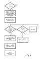
- Fig. 4 depicts a flow chart of a method for identifying or specifying the kind of operation problem which may occur during an operation of a laundry treatment apparatus 2 as described above.
- the above described sensing circuit of Fig. 3c may be used for implementing the below described method.
- the refrigerant temperature is monitored continuously or repeatedly during an operation cycle of the apparatus 2.
- the active switch 26 is opened and a timer is started to measure the compressor switch-off time.
- a sensing circuit e.g. a sensing circuit as described above
- a sensing circuit detects an operating voltage or current
- no electrical fault For example a refrigerant leak may be the cause of the refrigerant temperature drop.
- the compressor 14 may be switched-on, i.e. the active switch 26 may be closed and an estimation and correction of an operation value may be restarted as described above.
- a wiring problem or a defect of the compressor 14 is indicated. Subsequently the operation of the treatment apparatus is stopped. A corresponding error message may be memorised or displayed for precisely identifying the problem involving the machine.
Landscapes
- Engineering & Computer Science (AREA)
- Textile Engineering (AREA)
- Control Of Washing Machine And Dryer (AREA)
Priority Applications (1)
| Application Number | Priority Date | Filing Date | Title |
|---|---|---|---|
| EP14162965.9A EP2927366B1 (de) | 2014-03-31 | 2014-03-31 | Wäschebehandlungsvorrichtung und Betriebsverfahren |
Applications Claiming Priority (1)
| Application Number | Priority Date | Filing Date | Title |
|---|---|---|---|
| EP14162965.9A EP2927366B1 (de) | 2014-03-31 | 2014-03-31 | Wäschebehandlungsvorrichtung und Betriebsverfahren |
Publications (2)
| Publication Number | Publication Date |
|---|---|
| EP2927366A1 true EP2927366A1 (de) | 2015-10-07 |
| EP2927366B1 EP2927366B1 (de) | 2020-09-30 |
Family
ID=50397007
Family Applications (1)
| Application Number | Title | Priority Date | Filing Date |
|---|---|---|---|
| EP14162965.9A Active EP2927366B1 (de) | 2014-03-31 | 2014-03-31 | Wäschebehandlungsvorrichtung und Betriebsverfahren |
Country Status (1)
| Country | Link |
|---|---|
| EP (1) | EP2927366B1 (de) |
Cited By (5)
| Publication number | Priority date | Publication date | Assignee | Title |
|---|---|---|---|---|
| WO2018121850A1 (en) * | 2016-12-28 | 2018-07-05 | Electrolux Appliances Aktiebolag | Appliance with reliable information of a drying cycle |
| WO2020259848A1 (en) * | 2019-06-28 | 2020-12-30 | Electrolux Appliances Aktiebolag | Laundry drying machine and control method thereof |
| CN114182510A (zh) * | 2021-12-31 | 2022-03-15 | 广东美的白色家电技术创新中心有限公司 | 干衣机控制方法、装置、干衣机及存储介质 |
| WO2023117124A1 (en) | 2021-12-23 | 2023-06-29 | Electrolux Appliances Aktiebolag | Method to estimate the time to end of a laundry-drying cycle and laundry drying machine to carry out said method |
| US11920272B2 (en) | 2018-03-07 | 2024-03-05 | Electrolux Appliances Aktiebolag | Appliance with capacitive humidity sensor |
Families Citing this family (1)
| Publication number | Priority date | Publication date | Assignee | Title |
|---|---|---|---|---|
| US12252837B2 (en) | 2022-01-05 | 2025-03-18 | Haier Us Appliance Solutions, Inc. | Dryer appliance load detection |
Citations (6)
| Publication number | Priority date | Publication date | Assignee | Title |
|---|---|---|---|---|
| JPH04197398A (ja) * | 1990-11-29 | 1992-07-16 | Hitachi Ltd | 衣類乾燥機 |
| WO2004079078A1 (ja) * | 2003-03-06 | 2004-09-16 | Kabushiki Kaisha Toshiba | ドラム式洗濯機 |
| US6941674B2 (en) | 2003-08-12 | 2005-09-13 | Lg Electronics Inc. | Method and apparatus for detecting residual drying time of clothes dryer |
| EP2333149A1 (de) * | 2010-11-22 | 2011-06-15 | V-Zug AG | Wäschetrockner mit Umgebungstemperatursensor |
| EP2679718A1 (de) | 2012-06-29 | 2014-01-01 | Electrolux Home Products Corporation N.V. | Wäsche- oder Geschirrbehandlungsmaschine |
| EP2733252A1 (de) * | 2012-11-16 | 2014-05-21 | Electrolux Home Products Corporation N.V. | Verfahren für den Betrieb eines Wäschetrockners mit Wärmepumpe und Wäschetrockner mit Wärmepumpe oder Waschmaschine mit Wärmepumpe mit Trocknungsfunktion |
-
2014
- 2014-03-31 EP EP14162965.9A patent/EP2927366B1/de active Active
Patent Citations (6)
| Publication number | Priority date | Publication date | Assignee | Title |
|---|---|---|---|---|
| JPH04197398A (ja) * | 1990-11-29 | 1992-07-16 | Hitachi Ltd | 衣類乾燥機 |
| WO2004079078A1 (ja) * | 2003-03-06 | 2004-09-16 | Kabushiki Kaisha Toshiba | ドラム式洗濯機 |
| US6941674B2 (en) | 2003-08-12 | 2005-09-13 | Lg Electronics Inc. | Method and apparatus for detecting residual drying time of clothes dryer |
| EP2333149A1 (de) * | 2010-11-22 | 2011-06-15 | V-Zug AG | Wäschetrockner mit Umgebungstemperatursensor |
| EP2679718A1 (de) | 2012-06-29 | 2014-01-01 | Electrolux Home Products Corporation N.V. | Wäsche- oder Geschirrbehandlungsmaschine |
| EP2733252A1 (de) * | 2012-11-16 | 2014-05-21 | Electrolux Home Products Corporation N.V. | Verfahren für den Betrieb eines Wäschetrockners mit Wärmepumpe und Wäschetrockner mit Wärmepumpe oder Waschmaschine mit Wärmepumpe mit Trocknungsfunktion |
Cited By (12)
| Publication number | Priority date | Publication date | Assignee | Title |
|---|---|---|---|---|
| WO2018121850A1 (en) * | 2016-12-28 | 2018-07-05 | Electrolux Appliances Aktiebolag | Appliance with reliable information of a drying cycle |
| CN110226004A (zh) * | 2016-12-28 | 2019-09-10 | 伊莱克斯家用电器股份公司 | 具有可靠的干燥周期信息的器具 |
| CN110226004B (zh) * | 2016-12-28 | 2021-11-12 | 伊莱克斯家用电器股份公司 | 具有可靠的干燥周期信息的器具 |
| US11686041B2 (en) | 2016-12-28 | 2023-06-27 | Electrolux Appliances Aktiebolag | Appliance with reliable information of a drying cycle |
| AU2016434982B2 (en) * | 2016-12-28 | 2023-09-28 | Electrolux Appliances Aktiebolag | Appliance with reliable information of a drying cycle |
| US12553173B2 (en) | 2016-12-28 | 2026-02-17 | Electrolux Appliances Aktiebolag | Appliance with reliable information of a drying cycle |
| US11920272B2 (en) | 2018-03-07 | 2024-03-05 | Electrolux Appliances Aktiebolag | Appliance with capacitive humidity sensor |
| WO2020259848A1 (en) * | 2019-06-28 | 2020-12-30 | Electrolux Appliances Aktiebolag | Laundry drying machine and control method thereof |
| CN114127357A (zh) * | 2019-06-28 | 2022-03-01 | 伊莱克斯家用电器股份公司 | 衣物干燥机及其控制方法 |
| US20220349114A1 (en) * | 2019-06-28 | 2022-11-03 | Electrolux Appliances Aktiebolag | Laundry drying machine and control method thereof |
| WO2023117124A1 (en) | 2021-12-23 | 2023-06-29 | Electrolux Appliances Aktiebolag | Method to estimate the time to end of a laundry-drying cycle and laundry drying machine to carry out said method |
| CN114182510A (zh) * | 2021-12-31 | 2022-03-15 | 广东美的白色家电技术创新中心有限公司 | 干衣机控制方法、装置、干衣机及存储介质 |
Also Published As
| Publication number | Publication date |
|---|---|
| EP2927366B1 (de) | 2020-09-30 |
Similar Documents
| Publication | Publication Date | Title |
|---|---|---|
| EP2832918B1 (de) | Wäschebehandlungsvorrichtung und verfahren zum betreiben einer wäschebehandlungsvorrichtung | |
| EP2927366B1 (de) | Wäschebehandlungsvorrichtung und Betriebsverfahren | |
| CN106661816B (zh) | 加热器单元具有可调温度阈值的衣物干燥设备 | |
| EP2811064B1 (de) | Wäschebehandlungsvorrichtung mit temperaturabhängiger Steuerung | |
| EP2927365B1 (de) | Wäschetrocknungsverfahren und Wäschetrockner zur Durchführung desselben | |
| EP3124680B1 (de) | Verfahren zur anpassung von betriebsparametern beim trocknen in einem wärmepumpentrockner | |
| US8468717B2 (en) | Method to detect an end of cycle in a clothes dryer | |
| WO2015082011A1 (en) | A method for controlling a laundry drying machine of the type comprising a heat pump system and a corresponding laundry drying machine | |
| WO2014187494A1 (en) | Heat pump type laundry dryer and method of drying laundry using the same | |
| EP3059342B1 (de) | Verfahren zum betrieb einer wäschebehandlungsvorrichtung unter verwendung von betriebszustandsinformationen | |
| CN106436227B (zh) | 一种干衣机及其故障自检方法 | |
| EP3919671B1 (de) | Verfahren zum betrieb einer wäschetrocknungsmaschine, die mit einem wärmepumpensystem ausgestattet ist, und wäschetrocknungsmaschine zur implementierung des besagten verfahrens | |
| EP2927367A1 (de) | Verfahren zum Durchführen eines Trocknungszyklus in einer Wäschebehandlungsmaschine, Wäschebehandlungsvorrichtung und elektronische Steuereinheit | |
| EP2441880B1 (de) | Verfahren zum Trocknen von Kleidern in einem Trockner und Feuchtigkeitsbeurteilungssteuerung zum Erhalt einer automatischen Zyklusbeendigung | |
| EP2840179B1 (de) | Wäschebehandlungsvorrichtung und Verfahren zum Betreiben einer Wäschebehandlungsvorrichtung | |
| EP2610401B1 (de) | System und Verfahren zur Bewertung einer Wäscheladung in einem Drehtrommel-Trockner | |
| KR20180090130A (ko) | 의류 건조기 및 의류 건조기의 제어방법 | |
| EP3919670B1 (de) | Verfahren zum betrieb einer wäschetrocknungsmaschine, die mit einem wärmepumpensystem ausgestattet ist, und wäschetrocknungsmaschine zur implementierung des besagten verfahrens | |
| WO2017005528A1 (en) | A heat pump laundry dryer comprising a heater | |
| EP2599913A1 (de) | System zur Bestimmung der Dauer eines Trocknungszyklus in einem Wäschetrockner mit Drehtrommel | |
| EP2604751A1 (de) | Wäschetrocknermaschine und Steuerungsverfahren dafür |
Legal Events
| Date | Code | Title | Description |
|---|---|---|---|
| PUAI | Public reference made under article 153(3) epc to a published international application that has entered the european phase |
Free format text: ORIGINAL CODE: 0009012 |
|
| AK | Designated contracting states |
Kind code of ref document: A1 Designated state(s): AL AT BE BG CH CY CZ DE DK EE ES FI FR GB GR HR HU IE IS IT LI LT LU LV MC MK MT NL NO PL PT RO RS SE SI SK SM TR |
|
| AX | Request for extension of the european patent |
Extension state: BA ME |
|
| 17P | Request for examination filed |
Effective date: 20160407 |
|
| RBV | Designated contracting states (corrected) |
Designated state(s): AL AT BE BG CH CY CZ DE DK EE ES FI FR GB GR HR HU IE IS IT LI LT LU LV MC MK MT NL NO PL PT RO RS SE SI SK SM TR |
|
| REG | Reference to a national code |
Ref country code: DE Ref legal event code: R079 Ref document number: 602014070668 Country of ref document: DE Free format text: PREVIOUS MAIN CLASS: D06F0058280000 Ipc: D06F0058300000 |
|
| RIC1 | Information provided on ipc code assigned before grant |
Ipc: D06F 58/30 20200101AFI20200407BHEP |
|
| GRAP | Despatch of communication of intention to grant a patent |
Free format text: ORIGINAL CODE: EPIDOSNIGR1 |
|
| STAA | Information on the status of an ep patent application or granted ep patent |
Free format text: STATUS: GRANT OF PATENT IS INTENDED |
|
| INTG | Intention to grant announced |
Effective date: 20200515 |
|
| GRAS | Grant fee paid |
Free format text: ORIGINAL CODE: EPIDOSNIGR3 |
|
| GRAA | (expected) grant |
Free format text: ORIGINAL CODE: 0009210 |
|
| STAA | Information on the status of an ep patent application or granted ep patent |
Free format text: STATUS: THE PATENT HAS BEEN GRANTED |
|
| AK | Designated contracting states |
Kind code of ref document: B1 Designated state(s): AL AT BE BG CH CY CZ DE DK EE ES FI FR GB GR HR HU IE IS IT LI LT LU LV MC MK MT NL NO PL PT RO RS SE SI SK SM TR |
|
| REG | Reference to a national code |
Ref country code: GB Ref legal event code: FG4D Ref country code: CH Ref legal event code: EP |
|
| REG | Reference to a national code |
Ref country code: AT Ref legal event code: REF Ref document number: 1318904 Country of ref document: AT Kind code of ref document: T Effective date: 20201015 Ref country code: DE Ref legal event code: R096 Ref document number: 602014070668 Country of ref document: DE |
|
| REG | Reference to a national code |
Ref country code: IE Ref legal event code: FG4D |
|
| PG25 | Lapsed in a contracting state [announced via postgrant information from national office to epo] |
Ref country code: HR Free format text: LAPSE BECAUSE OF FAILURE TO SUBMIT A TRANSLATION OF THE DESCRIPTION OR TO PAY THE FEE WITHIN THE PRESCRIBED TIME-LIMIT Effective date: 20200930 Ref country code: SE Free format text: LAPSE BECAUSE OF FAILURE TO SUBMIT A TRANSLATION OF THE DESCRIPTION OR TO PAY THE FEE WITHIN THE PRESCRIBED TIME-LIMIT Effective date: 20200930 Ref country code: FI Free format text: LAPSE BECAUSE OF FAILURE TO SUBMIT A TRANSLATION OF THE DESCRIPTION OR TO PAY THE FEE WITHIN THE PRESCRIBED TIME-LIMIT Effective date: 20200930 Ref country code: NO Free format text: LAPSE BECAUSE OF FAILURE TO SUBMIT A TRANSLATION OF THE DESCRIPTION OR TO PAY THE FEE WITHIN THE PRESCRIBED TIME-LIMIT Effective date: 20201230 Ref country code: BG Free format text: LAPSE BECAUSE OF FAILURE TO SUBMIT A TRANSLATION OF THE DESCRIPTION OR TO PAY THE FEE WITHIN THE PRESCRIBED TIME-LIMIT Effective date: 20201230 Ref country code: GR Free format text: LAPSE BECAUSE OF FAILURE TO SUBMIT A TRANSLATION OF THE DESCRIPTION OR TO PAY THE FEE WITHIN THE PRESCRIBED TIME-LIMIT Effective date: 20201231 |
|
| REG | Reference to a national code |
Ref country code: AT Ref legal event code: MK05 Ref document number: 1318904 Country of ref document: AT Kind code of ref document: T Effective date: 20200930 |
|
| PG25 | Lapsed in a contracting state [announced via postgrant information from national office to epo] |
Ref country code: RS Free format text: LAPSE BECAUSE OF FAILURE TO SUBMIT A TRANSLATION OF THE DESCRIPTION OR TO PAY THE FEE WITHIN THE PRESCRIBED TIME-LIMIT Effective date: 20200930 Ref country code: LV Free format text: LAPSE BECAUSE OF FAILURE TO SUBMIT A TRANSLATION OF THE DESCRIPTION OR TO PAY THE FEE WITHIN THE PRESCRIBED TIME-LIMIT Effective date: 20200930 |
|
| REG | Reference to a national code |
Ref country code: NL Ref legal event code: MP Effective date: 20200930 |
|
| REG | Reference to a national code |
Ref country code: LT Ref legal event code: MG4D |
|
| PG25 | Lapsed in a contracting state [announced via postgrant information from national office to epo] |
Ref country code: RO Free format text: LAPSE BECAUSE OF FAILURE TO SUBMIT A TRANSLATION OF THE DESCRIPTION OR TO PAY THE FEE WITHIN THE PRESCRIBED TIME-LIMIT Effective date: 20200930 Ref country code: SM Free format text: LAPSE BECAUSE OF FAILURE TO SUBMIT A TRANSLATION OF THE DESCRIPTION OR TO PAY THE FEE WITHIN THE PRESCRIBED TIME-LIMIT Effective date: 20200930 Ref country code: NL Free format text: LAPSE BECAUSE OF FAILURE TO SUBMIT A TRANSLATION OF THE DESCRIPTION OR TO PAY THE FEE WITHIN THE PRESCRIBED TIME-LIMIT Effective date: 20200930 Ref country code: LT Free format text: LAPSE BECAUSE OF FAILURE TO SUBMIT A TRANSLATION OF THE DESCRIPTION OR TO PAY THE FEE WITHIN THE PRESCRIBED TIME-LIMIT Effective date: 20200930 Ref country code: PT Free format text: LAPSE BECAUSE OF FAILURE TO SUBMIT A TRANSLATION OF THE DESCRIPTION OR TO PAY THE FEE WITHIN THE PRESCRIBED TIME-LIMIT Effective date: 20210201 Ref country code: EE Free format text: LAPSE BECAUSE OF FAILURE TO SUBMIT A TRANSLATION OF THE DESCRIPTION OR TO PAY THE FEE WITHIN THE PRESCRIBED TIME-LIMIT Effective date: 20200930 Ref country code: CZ Free format text: LAPSE BECAUSE OF FAILURE TO SUBMIT A TRANSLATION OF THE DESCRIPTION OR TO PAY THE FEE WITHIN THE PRESCRIBED TIME-LIMIT Effective date: 20200930 |
|
| PG25 | Lapsed in a contracting state [announced via postgrant information from national office to epo] |
Ref country code: IS Free format text: LAPSE BECAUSE OF FAILURE TO SUBMIT A TRANSLATION OF THE DESCRIPTION OR TO PAY THE FEE WITHIN THE PRESCRIBED TIME-LIMIT Effective date: 20210130 Ref country code: PL Free format text: LAPSE BECAUSE OF FAILURE TO SUBMIT A TRANSLATION OF THE DESCRIPTION OR TO PAY THE FEE WITHIN THE PRESCRIBED TIME-LIMIT Effective date: 20200930 Ref country code: AL Free format text: LAPSE BECAUSE OF FAILURE TO SUBMIT A TRANSLATION OF THE DESCRIPTION OR TO PAY THE FEE WITHIN THE PRESCRIBED TIME-LIMIT Effective date: 20200930 Ref country code: AT Free format text: LAPSE BECAUSE OF FAILURE TO SUBMIT A TRANSLATION OF THE DESCRIPTION OR TO PAY THE FEE WITHIN THE PRESCRIBED TIME-LIMIT Effective date: 20200930 Ref country code: ES Free format text: LAPSE BECAUSE OF FAILURE TO SUBMIT A TRANSLATION OF THE DESCRIPTION OR TO PAY THE FEE WITHIN THE PRESCRIBED TIME-LIMIT Effective date: 20200930 |
|
| PG25 | Lapsed in a contracting state [announced via postgrant information from national office to epo] |
Ref country code: SK Free format text: LAPSE BECAUSE OF FAILURE TO SUBMIT A TRANSLATION OF THE DESCRIPTION OR TO PAY THE FEE WITHIN THE PRESCRIBED TIME-LIMIT Effective date: 20200930 |
|
| REG | Reference to a national code |
Ref country code: DE Ref legal event code: R097 Ref document number: 602014070668 Country of ref document: DE |
|
| PLBE | No opposition filed within time limit |
Free format text: ORIGINAL CODE: 0009261 |
|
| STAA | Information on the status of an ep patent application or granted ep patent |
Free format text: STATUS: NO OPPOSITION FILED WITHIN TIME LIMIT |
|
| PG25 | Lapsed in a contracting state [announced via postgrant information from national office to epo] |
Ref country code: DK Free format text: LAPSE BECAUSE OF FAILURE TO SUBMIT A TRANSLATION OF THE DESCRIPTION OR TO PAY THE FEE WITHIN THE PRESCRIBED TIME-LIMIT Effective date: 20200930 |
|
| 26N | No opposition filed |
Effective date: 20210701 |
|
| PG25 | Lapsed in a contracting state [announced via postgrant information from national office to epo] |
Ref country code: MC Free format text: LAPSE BECAUSE OF FAILURE TO SUBMIT A TRANSLATION OF THE DESCRIPTION OR TO PAY THE FEE WITHIN THE PRESCRIBED TIME-LIMIT Effective date: 20200930 |
|
| REG | Reference to a national code |
Ref country code: CH Ref legal event code: PL |
|
| GBPC | Gb: european patent ceased through non-payment of renewal fee |
Effective date: 20210331 |
|
| PG25 | Lapsed in a contracting state [announced via postgrant information from national office to epo] |
Ref country code: SI Free format text: LAPSE BECAUSE OF FAILURE TO SUBMIT A TRANSLATION OF THE DESCRIPTION OR TO PAY THE FEE WITHIN THE PRESCRIBED TIME-LIMIT Effective date: 20200930 |
|
| REG | Reference to a national code |
Ref country code: BE Ref legal event code: MM Effective date: 20210331 |
|
| PG25 | Lapsed in a contracting state [announced via postgrant information from national office to epo] |
Ref country code: LI Free format text: LAPSE BECAUSE OF NON-PAYMENT OF DUE FEES Effective date: 20210331 Ref country code: LU Free format text: LAPSE BECAUSE OF NON-PAYMENT OF DUE FEES Effective date: 20210331 Ref country code: CH Free format text: LAPSE BECAUSE OF NON-PAYMENT OF DUE FEES Effective date: 20210331 Ref country code: IE Free format text: LAPSE BECAUSE OF NON-PAYMENT OF DUE FEES Effective date: 20210331 Ref country code: GB Free format text: LAPSE BECAUSE OF NON-PAYMENT OF DUE FEES Effective date: 20210331 Ref country code: FR Free format text: LAPSE BECAUSE OF NON-PAYMENT OF DUE FEES Effective date: 20210331 |
|
| PG25 | Lapsed in a contracting state [announced via postgrant information from national office to epo] |
Ref country code: IS Free format text: LAPSE BECAUSE OF FAILURE TO SUBMIT A TRANSLATION OF THE DESCRIPTION OR TO PAY THE FEE WITHIN THE PRESCRIBED TIME-LIMIT Effective date: 20210130 |
|
| PG25 | Lapsed in a contracting state [announced via postgrant information from national office to epo] |
Ref country code: BE Free format text: LAPSE BECAUSE OF NON-PAYMENT OF DUE FEES Effective date: 20210331 |
|
| PG25 | Lapsed in a contracting state [announced via postgrant information from national office to epo] |
Ref country code: HU Free format text: LAPSE BECAUSE OF FAILURE TO SUBMIT A TRANSLATION OF THE DESCRIPTION OR TO PAY THE FEE WITHIN THE PRESCRIBED TIME-LIMIT; INVALID AB INITIO Effective date: 20140331 |
|
| PG25 | Lapsed in a contracting state [announced via postgrant information from national office to epo] |
Ref country code: CY Free format text: LAPSE BECAUSE OF FAILURE TO SUBMIT A TRANSLATION OF THE DESCRIPTION OR TO PAY THE FEE WITHIN THE PRESCRIBED TIME-LIMIT Effective date: 20200930 |
|
| P01 | Opt-out of the competence of the unified patent court (upc) registered |
Effective date: 20230625 |
|
| PG25 | Lapsed in a contracting state [announced via postgrant information from national office to epo] |
Ref country code: MK Free format text: LAPSE BECAUSE OF FAILURE TO SUBMIT A TRANSLATION OF THE DESCRIPTION OR TO PAY THE FEE WITHIN THE PRESCRIBED TIME-LIMIT Effective date: 20200930 |
|
| PG25 | Lapsed in a contracting state [announced via postgrant information from national office to epo] |
Ref country code: MT Free format text: LAPSE BECAUSE OF FAILURE TO SUBMIT A TRANSLATION OF THE DESCRIPTION OR TO PAY THE FEE WITHIN THE PRESCRIBED TIME-LIMIT Effective date: 20200930 |
|
| PGFP | Annual fee paid to national office [announced via postgrant information from national office to epo] |
Ref country code: IT Payment date: 20250321 Year of fee payment: 12 |
|
| PG25 | Lapsed in a contracting state [announced via postgrant information from national office to epo] |
Ref country code: TR Free format text: LAPSE BECAUSE OF FAILURE TO SUBMIT A TRANSLATION OF THE DESCRIPTION OR TO PAY THE FEE WITHIN THE PRESCRIBED TIME-LIMIT Effective date: 20200930 |
|
| PGFP | Annual fee paid to national office [announced via postgrant information from national office to epo] |
Ref country code: DE Payment date: 20260320 Year of fee payment: 13 |