EP2927460A1 - Turbine à gaz - Google Patents
Turbine à gaz Download PDFInfo
- Publication number
- EP2927460A1 EP2927460A1 EP14162725.7A EP14162725A EP2927460A1 EP 2927460 A1 EP2927460 A1 EP 2927460A1 EP 14162725 A EP14162725 A EP 14162725A EP 2927460 A1 EP2927460 A1 EP 2927460A1
- Authority
- EP
- European Patent Office
- Prior art keywords
- gas turbine
- housing
- combustion chamber
- compressor
- wall
- Prior art date
- Legal status (The legal status is an assumption and is not a legal conclusion. Google has not performed a legal analysis and makes no representation as to the accuracy of the status listed.)
- Withdrawn
Links
- 238000002485 combustion reaction Methods 0.000 claims abstract description 44
- 239000007789 gas Substances 0.000 description 68
- 238000001816 cooling Methods 0.000 description 13
- 239000002918 waste heat Substances 0.000 description 9
- 239000000463 material Substances 0.000 description 8
- 239000000446 fuel Substances 0.000 description 6
- 238000013461 design Methods 0.000 description 5
- 230000000694 effects Effects 0.000 description 5
- QVGXLLKOCUKJST-UHFFFAOYSA-N atomic oxygen Chemical compound [O] QVGXLLKOCUKJST-UHFFFAOYSA-N 0.000 description 4
- 238000000034 method Methods 0.000 description 4
- 239000001301 oxygen Substances 0.000 description 4
- 229910052760 oxygen Inorganic materials 0.000 description 4
- 230000008901 benefit Effects 0.000 description 3
- 238000007906 compression Methods 0.000 description 3
- 239000000203 mixture Substances 0.000 description 3
- 230000008569 process Effects 0.000 description 3
- 230000006835 compression Effects 0.000 description 2
- 238000005516 engineering process Methods 0.000 description 2
- 230000002349 favourable effect Effects 0.000 description 2
- 230000010354 integration Effects 0.000 description 2
- 238000004519 manufacturing process Methods 0.000 description 2
- 230000004048 modification Effects 0.000 description 2
- 238000012986 modification Methods 0.000 description 2
- 238000000926 separation method Methods 0.000 description 2
- 210000002023 somite Anatomy 0.000 description 2
- 230000006978 adaptation Effects 0.000 description 1
- 238000005056 compaction Methods 0.000 description 1
- 238000011161 development Methods 0.000 description 1
- 230000018109 developmental process Effects 0.000 description 1
- 230000006872 improvement Effects 0.000 description 1
- 230000007246 mechanism Effects 0.000 description 1
- 238000005192 partition Methods 0.000 description 1
- 230000001172 regenerating effect Effects 0.000 description 1
- 238000009420 retrofitting Methods 0.000 description 1
- 238000012360 testing method Methods 0.000 description 1
- 238000012546 transfer Methods 0.000 description 1
- 230000009466 transformation Effects 0.000 description 1
- 238000011144 upstream manufacturing Methods 0.000 description 1
Images

Classifications
-
- F—MECHANICAL ENGINEERING; LIGHTING; HEATING; WEAPONS; BLASTING
- F02—COMBUSTION ENGINES; HOT-GAS OR COMBUSTION-PRODUCT ENGINE PLANTS
- F02C—GAS-TURBINE PLANTS; AIR INTAKES FOR JET-PROPULSION PLANTS; CONTROLLING FUEL SUPPLY IN AIR-BREATHING JET-PROPULSION PLANTS
- F02C3/00—Gas-turbine plants characterised by the use of combustion products as the working fluid
- F02C3/14—Gas-turbine plants characterised by the use of combustion products as the working fluid characterised by the arrangement of the combustion chamber in the plant
-
- F—MECHANICAL ENGINEERING; LIGHTING; HEATING; WEAPONS; BLASTING
- F01—MACHINES OR ENGINES IN GENERAL; ENGINE PLANTS IN GENERAL; STEAM ENGINES
- F01D—NON-POSITIVE DISPLACEMENT MACHINES OR ENGINES, e.g. STEAM TURBINES
- F01D9/00—Stators
- F01D9/02—Nozzles; Nozzle boxes; Stator blades; Guide conduits, e.g. individual nozzles
- F01D9/023—Transition ducts between combustor cans and first stage of the turbine in gas-turbine engines; their cooling or sealings
-
- F—MECHANICAL ENGINEERING; LIGHTING; HEATING; WEAPONS; BLASTING
- F01—MACHINES OR ENGINES IN GENERAL; ENGINE PLANTS IN GENERAL; STEAM ENGINES
- F01D—NON-POSITIVE DISPLACEMENT MACHINES OR ENGINES, e.g. STEAM TURBINES
- F01D25/00—Component parts, details, or accessories, not provided for in, or of interest apart from, other groups
- F01D25/24—Casings; Casing parts, e.g. diaphragms, casing fastenings
-
- F—MECHANICAL ENGINEERING; LIGHTING; HEATING; WEAPONS; BLASTING
- F02—COMBUSTION ENGINES; HOT-GAS OR COMBUSTION-PRODUCT ENGINE PLANTS
- F02C—GAS-TURBINE PLANTS; AIR INTAKES FOR JET-PROPULSION PLANTS; CONTROLLING FUEL SUPPLY IN AIR-BREATHING JET-PROPULSION PLANTS
- F02C3/00—Gas-turbine plants characterised by the use of combustion products as the working fluid
- F02C3/04—Gas-turbine plants characterised by the use of combustion products as the working fluid having a turbine driving a compressor
-
- F—MECHANICAL ENGINEERING; LIGHTING; HEATING; WEAPONS; BLASTING
- F02—COMBUSTION ENGINES; HOT-GAS OR COMBUSTION-PRODUCT ENGINE PLANTS
- F02C—GAS-TURBINE PLANTS; AIR INTAKES FOR JET-PROPULSION PLANTS; CONTROLLING FUEL SUPPLY IN AIR-BREATHING JET-PROPULSION PLANTS
- F02C3/00—Gas-turbine plants characterised by the use of combustion products as the working fluid
- F02C3/14—Gas-turbine plants characterised by the use of combustion products as the working fluid characterised by the arrangement of the combustion chamber in the plant
- F02C3/145—Gas-turbine plants characterised by the use of combustion products as the working fluid characterised by the arrangement of the combustion chamber in the plant the combustion chamber being in the reverse flow-type
-
- F—MECHANICAL ENGINEERING; LIGHTING; HEATING; WEAPONS; BLASTING
- F02—COMBUSTION ENGINES; HOT-GAS OR COMBUSTION-PRODUCT ENGINE PLANTS
- F02C—GAS-TURBINE PLANTS; AIR INTAKES FOR JET-PROPULSION PLANTS; CONTROLLING FUEL SUPPLY IN AIR-BREATHING JET-PROPULSION PLANTS
- F02C7/00—Features, components parts, details or accessories, not provided for in, or of interest apart form groups F02C1/00 - F02C6/00; Air intakes for jet-propulsion plants
- F02C7/08—Heating air supply before combustion, e.g. by exhaust gases
-
- F—MECHANICAL ENGINEERING; LIGHTING; HEATING; WEAPONS; BLASTING
- F02—COMBUSTION ENGINES; HOT-GAS OR COMBUSTION-PRODUCT ENGINE PLANTS
- F02C—GAS-TURBINE PLANTS; AIR INTAKES FOR JET-PROPULSION PLANTS; CONTROLLING FUEL SUPPLY IN AIR-BREATHING JET-PROPULSION PLANTS
- F02C7/00—Features, components parts, details or accessories, not provided for in, or of interest apart form groups F02C1/00 - F02C6/00; Air intakes for jet-propulsion plants
- F02C7/08—Heating air supply before combustion, e.g. by exhaust gases
- F02C7/10—Heating air supply before combustion, e.g. by exhaust gases by means of regenerative heat-exchangers
-
- F—MECHANICAL ENGINEERING; LIGHTING; HEATING; WEAPONS; BLASTING
- F02—COMBUSTION ENGINES; HOT-GAS OR COMBUSTION-PRODUCT ENGINE PLANTS
- F02C—GAS-TURBINE PLANTS; AIR INTAKES FOR JET-PROPULSION PLANTS; CONTROLLING FUEL SUPPLY IN AIR-BREATHING JET-PROPULSION PLANTS
- F02C7/00—Features, components parts, details or accessories, not provided for in, or of interest apart form groups F02C1/00 - F02C6/00; Air intakes for jet-propulsion plants
- F02C7/12—Cooling of plants
- F02C7/16—Cooling of plants characterised by cooling medium
- F02C7/18—Cooling of plants characterised by cooling medium the medium being gaseous, e.g. air
-
- F—MECHANICAL ENGINEERING; LIGHTING; HEATING; WEAPONS; BLASTING
- F02—COMBUSTION ENGINES; HOT-GAS OR COMBUSTION-PRODUCT ENGINE PLANTS
- F02C—GAS-TURBINE PLANTS; AIR INTAKES FOR JET-PROPULSION PLANTS; CONTROLLING FUEL SUPPLY IN AIR-BREATHING JET-PROPULSION PLANTS
- F02C9/00—Controlling gas-turbine plants; Controlling fuel supply in air- breathing jet-propulsion plants
- F02C9/16—Control of working fluid flow
- F02C9/18—Control of working fluid flow by bleeding, bypassing or acting on variable working fluid interconnections between turbines or compressors or their stages
-
- F—MECHANICAL ENGINEERING; LIGHTING; HEATING; WEAPONS; BLASTING
- F02—COMBUSTION ENGINES; HOT-GAS OR COMBUSTION-PRODUCT ENGINE PLANTS
- F02C—GAS-TURBINE PLANTS; AIR INTAKES FOR JET-PROPULSION PLANTS; CONTROLLING FUEL SUPPLY IN AIR-BREATHING JET-PROPULSION PLANTS
- F02C9/00—Controlling gas-turbine plants; Controlling fuel supply in air- breathing jet-propulsion plants
- F02C9/16—Control of working fluid flow
- F02C9/20—Control of working fluid flow by throttling; by adjusting vanes
-
- F—MECHANICAL ENGINEERING; LIGHTING; HEATING; WEAPONS; BLASTING
- F04—POSITIVE - DISPLACEMENT MACHINES FOR LIQUIDS; PUMPS FOR LIQUIDS OR ELASTIC FLUIDS
- F04D—NON-POSITIVE-DISPLACEMENT PUMPS
- F04D29/00—Details, component parts, or accessories
- F04D29/40—Casings; Connections of working fluid
- F04D29/52—Casings; Connections of working fluid for axial pumps
- F04D29/54—Fluid-guiding means, e.g. diffusers
- F04D29/541—Specially adapted for elastic fluid pumps
-
- F—MECHANICAL ENGINEERING; LIGHTING; HEATING; WEAPONS; BLASTING
- F23—COMBUSTION APPARATUS; COMBUSTION PROCESSES
- F23R—GENERATING COMBUSTION PRODUCTS OF HIGH PRESSURE OR HIGH VELOCITY, e.g. GAS-TURBINE COMBUSTION CHAMBERS
- F23R3/00—Continuous combustion chambers using liquid or gaseous fuel
- F23R3/002—Wall structures
-
- F—MECHANICAL ENGINEERING; LIGHTING; HEATING; WEAPONS; BLASTING
- F23—COMBUSTION APPARATUS; COMBUSTION PROCESSES
- F23R—GENERATING COMBUSTION PRODUCTS OF HIGH PRESSURE OR HIGH VELOCITY, e.g. GAS-TURBINE COMBUSTION CHAMBERS
- F23R3/00—Continuous combustion chambers using liquid or gaseous fuel
- F23R3/42—Continuous combustion chambers using liquid or gaseous fuel characterised by the arrangement or form of the flame tubes or combustion chambers
- F23R3/60—Support structures; Attaching or mounting means
-
- F—MECHANICAL ENGINEERING; LIGHTING; HEATING; WEAPONS; BLASTING
- F05—INDEXING SCHEMES RELATING TO ENGINES OR PUMPS IN VARIOUS SUBCLASSES OF CLASSES F01-F04
- F05D—INDEXING SCHEME FOR ASPECTS RELATING TO NON-POSITIVE-DISPLACEMENT MACHINES OR ENGINES, GAS-TURBINES OR JET-PROPULSION PLANTS
- F05D2220/00—Application
- F05D2220/30—Application in turbines
- F05D2220/32—Application in turbines in gas turbines
-
- F—MECHANICAL ENGINEERING; LIGHTING; HEATING; WEAPONS; BLASTING
- F05—INDEXING SCHEMES RELATING TO ENGINES OR PUMPS IN VARIOUS SUBCLASSES OF CLASSES F01-F04
- F05D—INDEXING SCHEME FOR ASPECTS RELATING TO NON-POSITIVE-DISPLACEMENT MACHINES OR ENGINES, GAS-TURBINES OR JET-PROPULSION PLANTS
- F05D2230/00—Manufacture
- F05D2230/80—Repairing, retrofitting or upgrading methods
-
- F—MECHANICAL ENGINEERING; LIGHTING; HEATING; WEAPONS; BLASTING
- F05—INDEXING SCHEMES RELATING TO ENGINES OR PUMPS IN VARIOUS SUBCLASSES OF CLASSES F01-F04
- F05D—INDEXING SCHEME FOR ASPECTS RELATING TO NON-POSITIVE-DISPLACEMENT MACHINES OR ENGINES, GAS-TURBINES OR JET-PROPULSION PLANTS
- F05D2240/00—Components
- F05D2240/35—Combustors or associated equipment
-
- F—MECHANICAL ENGINEERING; LIGHTING; HEATING; WEAPONS; BLASTING
- F23—COMBUSTION APPARATUS; COMBUSTION PROCESSES
- F23R—GENERATING COMBUSTION PRODUCTS OF HIGH PRESSURE OR HIGH VELOCITY, e.g. GAS-TURBINE COMBUSTION CHAMBERS
- F23R2900/00—Special features of, or arrangements for continuous combustion chambers; Combustion processes therefor
- F23R2900/03342—Arrangement of silo-type combustion chambers
-
- Y—GENERAL TAGGING OF NEW TECHNOLOGICAL DEVELOPMENTS; GENERAL TAGGING OF CROSS-SECTIONAL TECHNOLOGIES SPANNING OVER SEVERAL SECTIONS OF THE IPC; TECHNICAL SUBJECTS COVERED BY FORMER USPC CROSS-REFERENCE ART COLLECTIONS [XRACs] AND DIGESTS
- Y02—TECHNOLOGIES OR APPLICATIONS FOR MITIGATION OR ADAPTATION AGAINST CLIMATE CHANGE
- Y02E—REDUCTION OF GREENHOUSE GAS [GHG] EMISSIONS, RELATED TO ENERGY GENERATION, TRANSMISSION OR DISTRIBUTION
- Y02E20/00—Combustion technologies with mitigation potential
- Y02E20/16—Combined cycle power plant [CCPP], or combined cycle gas turbine [CCGT]
Definitions
- the invention relates to a gas turbine, comprising a compressor, a middle housing, at least one combustion chamber, and an expansion turbine, wherein the or each combustion chamber is fluidly connected to the expansion turbine via an inner housing, which is guided through the interior of the center housing.
- thermodynamic cycle which describes this transformation, corresponds approximately to the Joule cycle.
- an oxygen-containing working gas in practice mostly air, is compressed by a compressor chamber, where it is heated from an initial temperature T 1 to T 2 , and the pressure rises.
- heat is supplied to the working gas in a combustion chamber at a constant pressure by burning the admixed fuel, whereby the temperature further increases to T 3 .
- the compressed, heated working gas then performs mechanical work by expanding and thereby driving the turbine via blades. In this case, the temperature drops to T 4 .
- the pressure also drops. A part of the mechanical work, which is won at the turbine, can be used for the compression in the first step.
- the working gas is removed by cooling at a constant pressure by cooling heat, whereby the temperature drops back to T 1 .
- the efficiency can be increased by using this waste heat by, for example, in a second cycle by the waste heat, a steam turbine of a second thermal power plant is operated (so-called “combined cycle” - or "gas-and-steam” technology).
- the efficiency can be improved by the degree of waste heat which can be supplied to the steam turbine.
- the system overhead increases for this improvement in efficiency, since now the entire steam cycle to connect to the gas turbine and control technology is tuned to this, thereby increasing the investment cost of a plant.
- many existing gas turbine thermal power plants can not readily be retrofitted with such due to the dimensions of the components of a steam cycle.
- a possible further solution here may be to use the waste heat of the exhaust gas of the gas turbine through the integration into a recuperator process, to further heat the precompressed working gas in the first step, before the heat of combustion of the fuel is supplied. Since in many gas turbines the temperature T 2 of the pre-compressed working gas is below the waste heat temperature T 4 , in the ideal model of this difference T 4 - T 2 corresponding amount of heat to the working gas can not be supplied by the energy content of the fuel, but can be saved, resulting in a corresponding increase in efficiency.
- a gas turbine comprising a compressor, a center housing, at least one combustion chamber, an expansion turbine, and a heat exchanger, wherein the or each combustion chamber is fluidly connected to the expansion turbine via an inner housing, which is guided through the interior of the center housing wherein the compressor is fluidically defined against the interior of the center housing by an annular collection chamber connected to an outlet of the compressor and having a number of outlets connected in operation to the cold side of the heat exchanger.
- the heat exchanger heat can be supplied by the waste heat of the gas turbine, and in particular the heated working gas in the heat exchanger while or supplied to each burner of the combustion chamber for oxygen supply.
- the compressor here is the totality of all individual, self-contained units to understand that meet the technical purpose of the compression of the working gas within the gas turbine and fluidly upstream of the or each burner.
- the invention proposes, despite the limited space between the compressor and the inner housing space in the center housing at the outlet of the compressor to provide a collection chamber from which the or each derivative is guided to the heat exchanger.
- this collection chamber is now a favorable pressure distribution possible without significant structural changes to the gas turbine are necessary.
- the newly arising effort in terms of design is limited to the flow of the working gas at the outlet of the compressor, in the collection chamber itself and in the respective derivative.
- the collection chamber is delimited by a wall extending from the outlet of the compressor to the middle housing against the interior of the center housing.
- the or each derivative is passed through the part of the housing of the gas turbine, which surrounds the compressor, and connects to the gap of the wall to the middle housing.
- the space in the center housing is limited, for example by a spatial proximity from the outlet of the compressor to the inner housing.
- the outlet of the compressor can be adapted to the available space, so that the flow guide, viewed in the axial direction, is guided by a manifold away from the center housing.
- the manifold can be designed rotationally symmetrical, so that the wall which delimits the collecting chamber against the interior of the center housing, is formed by a number of bulkhead plates, which extend from an edge of the manifold to the center housing.
- the middle housing in this case in particular have a circumferential groove in order to improve the fluidic delimitation effect of the wall.
- the outlet of the compressor is designed as an annular outlet diffuser.
- This is a special one frequently chosen structural variant in gas turbines, as can be achieved by the local slowing down of the flow velocity of the working gas for this yet another increase in pressure over the diffuser.
- An annular diffuser also ensures as homogeneous a pressure distribution as possible and a uniform mass flow of the working gas from the compressor into the collecting chamber.
- the outlet diffuser in the axial direction have a manifold away from the center housing, whereby the space required for the collection chamber space is reduced, since this can thus be arranged in the immediate vicinity of the compressor.
- a plurality of leads rotationally symmetrically lead away from the collection chamber, or lead away a plurality of groups of derivatives each rotationally symmetrical from the collection chamber.
- the or each combustion chamber is designed as a silo combustion chamber.
- the collecting chamber between the inner housing, which leads from the or each combustion chamber to the expansion turbine, and the compressor can be arranged, which is structurally particularly favorable, since only the collection chamber itself must be configured over an already existing concept.
- the or each silo combustion chamber has a combustion chamber bounding inner wall and an outer wall, wherein the outer wall surrounds the inner wall forming a cavity, wherein the inner wall merges into the inner housing, and wherein the cavity in the interior of the center housing passes.
- temperatures of up to 1400 ° C may occur during operation of the gas turbine, which leads to special load requirements on the material of the inner wall. Due to the double-walled design of the combustion chamber the cavity can be flowed through with a gas for better cooling of the inner wall, whereby the said load capacity requirements can be reduced and corresponding costs can be reduced.
- a direct fluidic connection to the interior of the center housing can be produced by the or each derivative via a bypass.
- a portion of the precompressed working gas can be passed into the interior of the center housing via the bypass, where the working gas can flow around the inner housing. Since during operation by the inner housing burned in the combustion chamber fuel-working gas mixture is led to the expansion turbine out, high temperatures can arise on the inner housing, which can lead to special load requirements on the material of the inner housing. The fact that the inner housing is flowed around by a part of the precompressed working gas, a cooling effect can be achieved, which reduces the said requirements.
- a bypass allows the discharge to the interior of the center housing to keep the interior of the center housing under similar pressure as the combustion chamber of the combustion chamber and the interior of the inner housing passing over it.
- a small pressure difference between said spaces simplifies the structural design of the inner housing.
- the bypass on a number of valves and a number of each connected to a valve pipes the connection of the or each derivative leads to the interior of the center housing via a valve and a pipe.
- the mass flow of the precompressed working gas from the compressor in the interior of the center housing and thus the cooling effect in particular on the inner housing can be controlled very easily.
- the or each valve is disposed within the middle housing at the respective discharge.
- the corresponding pipe does not have to be led out through the central housing of the gas turbine, which keeps the necessary structural changes compared to an existing concept low.
- the or each valve may also be arranged outside the gas turbine at the respective outlet. This may be advantageous if a particularly easy accessibility of the or each valve is desired during operation, for example, if the gas turbine is not to be operated in continuous use, but often approached and shut down after a certain period of operation, which may be a special fluidic requirements can result.
- the inner wall of the or each silo combustion chamber conveniently has a plurality of holes. Through such bores precompressed working gas can flow from the cavity due to the pressure difference in small quantities in the combustion chamber, where it contributes to the cooling of the material of the inner wall. This further reduces the temperature for which the materials used for the inner wall should be designed.
- the inner housing has a plurality of holes. Through such holes precompressed working gas from the interior of the center housing due to the pressure difference in small quantities in the connected to the combustion chamber interior of the inner housing, where it contributes to the cooling of the material of the inner housing. This further reduces the temperature for which the materials used for the inner housing should be designed.
- the invention further mentions a thermal power plant with a gas turbine as described above.
- the advantages of the gas turbine and its Further developments can be transferred analogously to the thermal power plant.
- FIG. 1 is a section of a gas turbine 1 is shown in an axial section.
- the gas turbine 1 comprises a compressor 2 with compressor chambers 4, which lead to an outlet 8 formed as an outlet diffuser 6.
- the outlet diffuser 6 leading away from the interior 10 of the middle housing 12, has a cross-sectionally U-shaped bend 14.
- a collection chamber 16 which is fluidically separated from the interior 10 of the center housing 12 by a wall 17.
- the circumferential wall 17 is formed by a circumferential partition plate 18 which extends radially from the outer edge 19 of the manifold 14 to the center housing 12. From the collection chamber 16, a derivative 20 is guided by the adjoining the center housing 12, the compressor 2 surrounding the front housing 22 and connected in a manner not shown with a heat exchanger.
- an inner housing 24 is guided, which connects the combustion chamber of a silo combustion chamber, not shown, with the expansion turbine 26.
- air is compressed as working gas in the compressor 2. This flows through the outlet diffuser 6 in the collection chamber 16 and is guided via the discharge line 20 and a not shown in the drawing line system to a heat exchanger, wherein a portion of the air is returned to the interior 10 of the center housing 12.
- the precompressed air can contribute to the cooling of the inner housing 24, through which a combusted fuel-air mixture flows from the combustion chamber to the expansion turbine 26, which results in elevated temperatures on the inner housing. Due to the cooling effect of the air partially recirculated into the interior of the inner housing, the material of the inner housing can be designed for lower maximum temperatures.
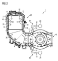
- FIG. 2 is shown in a cross-sectional view of a gas turbine 1 with a silo combustion chamber 28.
- the view is taken behind the collection chamber in the direction of the expansion turbine.
- the silo combustion chamber 28 comprises an inner wall 30 which, together with the flame tube bottom 32, delimits the combustion chamber 34 of the flame tube 36.
- the inner wall 30 and the flame tube bottom 32 are surrounded by an outer wall 40 to form a cavity 38.
- the inner wall 30 merges into the inner housing 24 at its end close to the axis, so that the combustion chamber 34 is fluidically connected to the interior of the inner housing 24.
- the outer wall 40 merges into the middle housing 12, so that the cavity 38 is connected directly to the inner space 10 of the middle housing 12.
- the inner housing 24 merges into the inner wall of a further silo combustion chamber, not illustrated here, which is substantially identical in design and symmetrical to the silo combustion chamber 28.
- the collection chamber In front of the inner housing 24, the collection chamber, not shown here, is arranged, which is connected via the manifold to the outlet diffuser of the compressor. From the collection chamber lead two leads 20 through the center housing 12 away from the collection chamber, which are shown here in cross section. The leads 20 lead to the cold side of a heat exchanger, not shown. From the discharge lines 20 leads via a valve 52, 54 a pipe 56, 58 through the middle housing 12 back into the interior 10 of the center housing 12.
- the inner housing 24 has as well as the inner wall 30 a plurality of holes 60.
- the air pre-compressed by the compressor is removed by the collecting chamber and passed via the discharge lines 20 in the direction of the cold side of the heat exchanger.
- the valves 52, 54 and the pipes 56, 58 in this case each form a bypass 62, 64, via which, under control of the mass flow, a portion of the air back into the interior 10 of the center housing 12 and thus into the cavity 38 between the inner wall 30th and the outer wall 40 can flow.
- the precompressed air can contribute to the cooling of the inner housing 42 and the inner wall 30, which are overflowed by the fuel-air mixture burned in the combustion chamber 34.
- the holes 60 lead to the fact that the compressed air, which is returned via the bypasses 62, 64, can flow into the interior of the flame tube 36 and the inner housing 24, which further improves the cooling effect.
- a thermodynamically most efficient operating point can be set.
- the air for oxygen supply to the burner 44 is due in a manner which is not the subject of the invention.
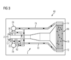
- FIG. 3 schematically a thermal power plant 66 is shown with a gas turbine 1, which has a heat exchanger 68. From the center housing 12 lead from the collection chamber, not shown in the drawing in the vicinity of the compressor 2 leads 20 to a conduit system 70 which has a bypass 62 which leads back through the center housing 12. The conduit system 70 is connected to the cold side 72 of the heat exchanger 68. From the hot side 74 of the heat exchanger 68, a line 76 leads in the direction of the two Silobrennsch 28th
- the air taken in the collecting chamber is led through the discharge lines 20 to the line system 70.
- a portion of the air is passed through the bypass 62 for cooling back into the interior of the center housing 12.
- the remaining air is passed through the conduit system 70 to the heat exchanger 68 where it is heated in fine tubes 78, which are flowed around by the waste heat of the silo separation chambers 28.
- the air thus heated is now passed via the line 76 to the silo separation chambers 28 and there supplied in a manner which is not the subject of the invention, the oxygen supply of the respective burner.
Landscapes
- Engineering & Computer Science (AREA)
- Chemical & Material Sciences (AREA)
- Combustion & Propulsion (AREA)
- Mechanical Engineering (AREA)
- General Engineering & Computer Science (AREA)
- Physics & Mathematics (AREA)
- Fluid Mechanics (AREA)
- Structures Of Non-Positive Displacement Pumps (AREA)
- Turbine Rotor Nozzle Sealing (AREA)
Priority Applications (5)
| Application Number | Priority Date | Filing Date | Title |
|---|---|---|---|
| EP14162725.7A EP2927460A1 (fr) | 2014-03-31 | 2014-03-31 | Turbine à gaz |
| US15/127,491 US9771812B2 (en) | 2014-03-31 | 2015-03-19 | Gas turbine |
| EP15712838.0A EP3099911B1 (fr) | 2014-03-31 | 2015-03-19 | Turbine à gaz |
| PCT/EP2015/055790 WO2015150093A1 (fr) | 2014-03-31 | 2015-03-19 | Turbine à gaz |
| CN201580017810.0A CN106133293B (zh) | 2014-03-31 | 2015-03-19 | 燃气轮机 |
Applications Claiming Priority (1)
| Application Number | Priority Date | Filing Date | Title |
|---|---|---|---|
| EP14162725.7A EP2927460A1 (fr) | 2014-03-31 | 2014-03-31 | Turbine à gaz |
Publications (1)
| Publication Number | Publication Date |
|---|---|
| EP2927460A1 true EP2927460A1 (fr) | 2015-10-07 |
Family
ID=50389973
Family Applications (2)
| Application Number | Title | Priority Date | Filing Date |
|---|---|---|---|
| EP14162725.7A Withdrawn EP2927460A1 (fr) | 2014-03-31 | 2014-03-31 | Turbine à gaz |
| EP15712838.0A Not-in-force EP3099911B1 (fr) | 2014-03-31 | 2015-03-19 | Turbine à gaz |
Family Applications After (1)
| Application Number | Title | Priority Date | Filing Date |
|---|---|---|---|
| EP15712838.0A Not-in-force EP3099911B1 (fr) | 2014-03-31 | 2015-03-19 | Turbine à gaz |
Country Status (4)
| Country | Link |
|---|---|
| US (1) | US9771812B2 (fr) |
| EP (2) | EP2927460A1 (fr) |
| CN (1) | CN106133293B (fr) |
| WO (1) | WO2015150093A1 (fr) |
Cited By (1)
| Publication number | Priority date | Publication date | Assignee | Title |
|---|---|---|---|---|
| WO2016079223A1 (fr) * | 2014-11-20 | 2016-05-26 | Siemens Aktiengesellschaft | Machine d'énergie thermique présentant des dispositifs de guidage de flux de sortie dans le diffuseur |
Families Citing this family (2)
| Publication number | Priority date | Publication date | Assignee | Title |
|---|---|---|---|---|
| US10677260B2 (en) * | 2017-02-21 | 2020-06-09 | General Electric Company | Turbine engine and method of manufacturing |
| DE102020116245B4 (de) * | 2020-06-19 | 2024-03-07 | Man Energy Solutions Se | Baugruppe einer Gasturbine mit Brennkammerluftbypass |
Citations (6)
| Publication number | Priority date | Publication date | Assignee | Title |
|---|---|---|---|---|
| US2713245A (en) * | 1952-11-24 | 1955-07-19 | Austin Motor Co Ltd | Internal combustion turbine power plants with regenerative exhaust treatment system |
| US3228190A (en) * | 1962-08-16 | 1966-01-11 | Power Jets Res & Dev Ltd | Gas turbine plant |
| US3367403A (en) * | 1965-09-03 | 1968-02-06 | United Aircraft Corp | Regenerator hub support |
| US3939904A (en) * | 1972-10-25 | 1976-02-24 | Beaufrere Albert H | Rotary disc regenerator |
| DE2458274A1 (de) * | 1974-12-10 | 1976-06-16 | United Turbine Ab & Co | Gasturbinenanlage |
| GB2232720A (en) * | 1989-06-15 | 1990-12-19 | Rolls Royce Business Ventures | Gas turbine engine power unit |
Family Cites Families (3)
| Publication number | Priority date | Publication date | Assignee | Title |
|---|---|---|---|---|
| US3010281A (en) * | 1957-12-24 | 1961-11-28 | Adolph J Cervenka | Toroidal combustion chamber |
| GB8914825D0 (en) * | 1989-06-28 | 1989-08-16 | Rolls Royce Plc | Gas turbine engine power unit |
| US7310938B2 (en) * | 2004-12-16 | 2007-12-25 | Siemens Power Generation, Inc. | Cooled gas turbine transition duct |
-
2014
- 2014-03-31 EP EP14162725.7A patent/EP2927460A1/fr not_active Withdrawn
-
2015
- 2015-03-19 EP EP15712838.0A patent/EP3099911B1/fr not_active Not-in-force
- 2015-03-19 WO PCT/EP2015/055790 patent/WO2015150093A1/fr not_active Ceased
- 2015-03-19 US US15/127,491 patent/US9771812B2/en not_active Expired - Fee Related
- 2015-03-19 CN CN201580017810.0A patent/CN106133293B/zh not_active Expired - Fee Related
Patent Citations (6)
| Publication number | Priority date | Publication date | Assignee | Title |
|---|---|---|---|---|
| US2713245A (en) * | 1952-11-24 | 1955-07-19 | Austin Motor Co Ltd | Internal combustion turbine power plants with regenerative exhaust treatment system |
| US3228190A (en) * | 1962-08-16 | 1966-01-11 | Power Jets Res & Dev Ltd | Gas turbine plant |
| US3367403A (en) * | 1965-09-03 | 1968-02-06 | United Aircraft Corp | Regenerator hub support |
| US3939904A (en) * | 1972-10-25 | 1976-02-24 | Beaufrere Albert H | Rotary disc regenerator |
| DE2458274A1 (de) * | 1974-12-10 | 1976-06-16 | United Turbine Ab & Co | Gasturbinenanlage |
| GB2232720A (en) * | 1989-06-15 | 1990-12-19 | Rolls Royce Business Ventures | Gas turbine engine power unit |
Cited By (1)
| Publication number | Priority date | Publication date | Assignee | Title |
|---|---|---|---|---|
| WO2016079223A1 (fr) * | 2014-11-20 | 2016-05-26 | Siemens Aktiengesellschaft | Machine d'énergie thermique présentant des dispositifs de guidage de flux de sortie dans le diffuseur |
Also Published As
| Publication number | Publication date |
|---|---|
| EP3099911A1 (fr) | 2016-12-07 |
| US20170130594A1 (en) | 2017-05-11 |
| CN106133293B (zh) | 2018-02-13 |
| US9771812B2 (en) | 2017-09-26 |
| WO2015150093A1 (fr) | 2015-10-08 |
| EP3099911B1 (fr) | 2018-06-27 |
| CN106133293A (zh) | 2016-11-16 |
Similar Documents
| Publication | Publication Date | Title |
|---|---|---|
| EP3186498B1 (fr) | Ensemble de turbine à gaz | |
| DE69808954T2 (de) | Abhitzedampferzeuger | |
| DE102012011294A1 (de) | Verfahren zum Kühlen einer Gasturbinenanlage sowie Gasturbinenanlage zur Durchführung des Verfahrens | |
| CH703587A2 (de) | Druckbetätigter Stopfen. | |
| CH707830A2 (de) | Überleitungskanal mit verbesserter Kühlung für eine Turbomaschine. | |
| DE102018123663A1 (de) | Brennstoffvorwärmsystem für eine Verbrennungsgasturbine | |
| DE10042317A1 (de) | Dampfturbine und Verfahren zur Einleitung von Beipassdampf | |
| EP3099911B1 (fr) | Turbine à gaz | |
| EP3397843A1 (fr) | Turbine à gaz équipée d'un piston à poussée axiale et d'un palier radial | |
| EP3099978B1 (fr) | Turbine à gaz avec une chambre de combustion de type silo | |
| DE102016216281A1 (de) | Bypassventil | |
| DE69811841T2 (de) | KüHLSYSTEM FüR DIE ENDSTüCKE DER VERBRENNUNGSKAMMER | |
| DE102009038323A1 (de) | Verfahren und Vorrichtung zur Verwertung von Biomasse | |
| WO2016055354A1 (fr) | Turbine à gaz pourvue de deux conduits d'alimentation à tourbillons pour refroidir le rotor | |
| EP1117913B1 (fr) | Prechauffage du combustible dans une turbine a gaz | |
| DE3011503A1 (de) | Verdichteranordnung fuer ein axialgasturbinentriebwerk | |
| DE102016202833A1 (de) | Gasturbine mit Kühlung über die hintere Hohlwelle | |
| EP2927459A1 (fr) | Turbine à gaz | |
| CH708973A2 (de) | Verdichterauslassgehäuseanordnung. | |
| EP1164273A2 (fr) | Turboréacteur avec échangeur de chaleur | |
| DE654640C (de) | Hochleistungsdampferzeuger mit Zwangdurchlauf des Arbeitsmittels | |
| DE874678C (de) | Roehrengaserhitzer, insbesondere fuer feste Brennstoffe, vorzugsweise zur Verwendungbei zweistufigen Gasturbinenanlagen | |
| DE102023209964A1 (de) | Verbrennungseinrichtung sowie Gasturbine mit Ammoniak-Cracker und Verfahren zum Betrieb einer Verbrennungseinrichtung sowie Gasturbine | |
| EP3921577B1 (fr) | Système de chambre de combustion à tubes et installation de turbine à gaz pourvue d'un tel système de chambre de combustion à tubes | |
| EP2987966A1 (fr) | Turbine à gaz dotée de canal de refroidissement divisé en sections annulaires |
Legal Events
| Date | Code | Title | Description |
|---|---|---|---|
| PUAI | Public reference made under article 153(3) epc to a published international application that has entered the european phase |
Free format text: ORIGINAL CODE: 0009012 |
|
| AK | Designated contracting states |
Kind code of ref document: A1 Designated state(s): AL AT BE BG CH CY CZ DE DK EE ES FI FR GB GR HR HU IE IS IT LI LT LU LV MC MK MT NL NO PL PT RO RS SE SI SK SM TR |
|
| AX | Request for extension of the european patent |
Extension state: BA ME |
|
| STAA | Information on the status of an ep patent application or granted ep patent |
Free format text: STATUS: THE APPLICATION IS DEEMED TO BE WITHDRAWN |
|
| 18D | Application deemed to be withdrawn |
Effective date: 20160408 |