EP2927562A1 - Lampe - Google Patents
Lampe Download PDFInfo
- Publication number
- EP2927562A1 EP2927562A1 EP15161707.3A EP15161707A EP2927562A1 EP 2927562 A1 EP2927562 A1 EP 2927562A1 EP 15161707 A EP15161707 A EP 15161707A EP 2927562 A1 EP2927562 A1 EP 2927562A1
- Authority
- EP
- European Patent Office
- Prior art keywords
- heat
- dissipating
- lamp
- light
- lens
- Prior art date
- Legal status (The legal status is an assumption and is not a legal conclusion. Google has not performed a legal analysis and makes no representation as to the accuracy of the status listed.)
- Withdrawn
Links
- 230000000717 retained effect Effects 0.000 claims description 4
- 230000017525 heat dissipation Effects 0.000 description 4
- 238000009423 ventilation Methods 0.000 description 2
- 230000000694 effects Effects 0.000 description 1
- 230000004048 modification Effects 0.000 description 1
- 238000012986 modification Methods 0.000 description 1
- 230000035939 shock Effects 0.000 description 1
Images


Classifications
-
- F—MECHANICAL ENGINEERING; LIGHTING; HEATING; WEAPONS; BLASTING
- F21—LIGHTING
- F21V—FUNCTIONAL FEATURES OR DETAILS OF LIGHTING DEVICES OR SYSTEMS THEREOF; STRUCTURAL COMBINATIONS OF LIGHTING DEVICES WITH OTHER ARTICLES, NOT OTHERWISE PROVIDED FOR
- F21V29/00—Protecting lighting devices from thermal damage; Cooling or heating arrangements specially adapted for lighting devices or systems
- F21V29/50—Cooling arrangements
- F21V29/70—Cooling arrangements characterised by passive heat-dissipating elements, e.g. heat-sinks
- F21V29/83—Cooling arrangements characterised by passive heat-dissipating elements, e.g. heat-sinks the elements having apertures, ducts or channels, e.g. heat radiation holes
-
- F—MECHANICAL ENGINEERING; LIGHTING; HEATING; WEAPONS; BLASTING
- F21—LIGHTING
- F21K—NON-ELECTRIC LIGHT SOURCES USING LUMINESCENCE; LIGHT SOURCES USING ELECTROCHEMILUMINESCENCE; LIGHT SOURCES USING CHARGES OF COMBUSTIBLE MATERIAL; LIGHT SOURCES USING SEMICONDUCTOR DEVICES AS LIGHT-GENERATING ELEMENTS; LIGHT SOURCES NOT OTHERWISE PROVIDED FOR
- F21K9/00—Light sources using semiconductor devices as light-generating elements, e.g. using light-emitting diodes [LED] or lasers
- F21K9/60—Optical arrangements integrated in the light source, e.g. for improving the colour rendering index or the light extraction
- F21K9/61—Optical arrangements integrated in the light source, e.g. for improving the colour rendering index or the light extraction using light guides
-
- F—MECHANICAL ENGINEERING; LIGHTING; HEATING; WEAPONS; BLASTING
- F21—LIGHTING
- F21V—FUNCTIONAL FEATURES OR DETAILS OF LIGHTING DEVICES OR SYSTEMS THEREOF; STRUCTURAL COMBINATIONS OF LIGHTING DEVICES WITH OTHER ARTICLES, NOT OTHERWISE PROVIDED FOR
- F21V23/00—Arrangement of electric circuit elements in or on lighting devices
- F21V23/003—Arrangement of electric circuit elements in or on lighting devices the elements being electronics drivers or controllers for operating the light source, e.g. for a LED array
- F21V23/007—Arrangement of electric circuit elements in or on lighting devices the elements being electronics drivers or controllers for operating the light source, e.g. for a LED array enclosed in a casing
- F21V23/009—Arrangement of electric circuit elements in or on lighting devices the elements being electronics drivers or controllers for operating the light source, e.g. for a LED array enclosed in a casing the casing being inside the housing of the lighting device
-
- G—PHYSICS
- G02—OPTICS
- G02B—OPTICAL ELEMENTS, SYSTEMS OR APPARATUS
- G02B6/00—Light guides; Structural details of arrangements comprising light guides and other optical elements, e.g. couplings
- G02B6/0001—Light guides; Structural details of arrangements comprising light guides and other optical elements, e.g. couplings specially adapted for lighting devices or systems
- G02B6/0011—Light guides; Structural details of arrangements comprising light guides and other optical elements, e.g. couplings specially adapted for lighting devices or systems the light guides being planar or of plate-like form
- G02B6/0013—Means for improving the coupling-in of light from the light source into the light guide
- G02B6/0023—Means for improving the coupling-in of light from the light source into the light guide provided by one optical element, or plurality thereof, placed between the light guide and the light source, or around the light source
- G02B6/003—Lens or lenticular sheet or layer
-
- F—MECHANICAL ENGINEERING; LIGHTING; HEATING; WEAPONS; BLASTING
- F21—LIGHTING
- F21Y—INDEXING SCHEME ASSOCIATED WITH SUBCLASSES F21K, F21L, F21S and F21V, RELATING TO THE FORM OR THE KIND OF THE LIGHT SOURCES OR OF THE COLOUR OF THE LIGHT EMITTED
- F21Y2115/00—Light-generating elements of semiconductor light sources
- F21Y2115/10—Light-emitting diodes [LED]
Definitions
- the invention relates to a lamp, more particularly to a lamp with ventilation function.
- a light-emitting diode is often used in lighting due to its long lifespan and shock-resistant characteristics.
- light-emission efficiency of the LED is affected by increase in temperature. Heat-dissipation, therefore, becomes a primary concern in LED lighting.
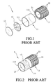
- a conventional LED lamp includes a lighting unit 1 and a heat-dissipating unit 2 attached behind the lighting unit 1.
- the lighting unit 1 includes a hollow body 11 that defines a channel with opposite open ends 111, a lighting module 12 that is disposed in the body 11, and an optic component 13 that is disposed in the body 11 and that is in front of the lighting module 12.
- the heat-dissipating unit 2 includes a main body 21, and a plurality of spaced-apart heat-dissipating fins 22 that extend outwardly and radially from the main body 21. The heat-dissipating unit 2 is in contact with the lighting module 12 for dissipating heat generated by the lighting module 12.
- the optic component 13 and the heat-dissipating unit 2 block respectively the opposite open ends 111 of the channel of the body 11 of the lighting unit 1, thereby preventing air from the external environment from flowing into the body 11 which would otherwise help heat dissipation.
- the heat-dissipating unit 2 is hence the only means of heat dissipation, and will need to be made larger if better heat-dissipating efficiency is desired.
- this is accompanied by the disadvantage of an increase in the overall size and weight of the conventional LED lamp.
- the object of the present invention is to provide a lamp with ventilation function that can alleviate the aforesaid drawbacks of the prior art.
- a lamp includes a heat-dissipating unit, a light source and a light guide unit.
- the heat-dissipating unit is formed with at least one heat-dissipating channel that has opposite open ends.
- the light source is disposed on the heat-dissipating unit.
- the light guide unit is disposed in front of the light source for guiding light that is emitted from the light source, and is formed with a vent hole that has opposite open ends in spatial communication with the heat-dissipating channel.
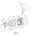
- the first embodiment of a lamp according to the present invention includes a heat-dissipating unit 3, a light source 4 disposed on the heat-dissipating unit 3, a light guide unit 5 disposed in front of the light source 4 for guiding light that is emitted from the light source 4, and a mounting seat 6 connected to the heat-dissipating unit 3.
- the heat-dissipating unit 3 includes a heat-dissipating seat 31 and a plurality of spaced-apart heat-dissipating components 32.
- the heat-dissipating seat 31 includes a main body 315 that has opposite front and rear end surfaces 312, 313, and two heat-dissipating channels 311.
- Each of the heat-dissipating channels 311 has opposite open ends.
- the open ends of each of the heat-dissipating channels 311 are formed respectively in the front and rear end surfaces 312, 313.
- the heat-dissipating components 32 are connected to the heat-dissipating seat 31 and disposed in the heat dissipating channels 311.
- the heat-dissipating seat 31 further includes a second engaging portion 314 that projects from the front end surface 312 of the main body 315 and that surrounds the open ends of the heat-dissipating channels 311 formed in the front end surface 312.
- the heat-dissipating seat 31 in other embodiments may be formed with only one heat-dissipating channel 311 that tapers rearwardly, as shown in Figs. 4 and 5(a ).
- the light source 4 includes an annular circuit board 42 that is coupled to the front end surface 312 of the heat-dissipating seat 31, that is surrounded by the second engaging portion 314 of the heat-dissipating seat 31, and that defines a through hole 41 therein, and a plurality light emitting members 43 that are connected to the annular circuit board 42.
- the through hole 41 is in spatial communication with the heat-dissipating channels 311.
- the light emitting members 43 are LEDs.
- the type of the light emitting members 43 is not limited to the disclosure herein.
- the light guide unit 5 includes a lens 51 that has a light incident surface 512 facing the heat-dissipating seat 31, and a light emitting surface 513 opposite to and larger than the light incident surface 512.
- the lens 51 is formed with a vent hole 511 that has opposite open ends formed respectively in the light incident surface 512 and the light emitting surface 513, and in spatial communication with the through hole 41.
- the light incident surface 512 is further formed with a first engaging portion 515 surrounding the vent hole 511 and engaged with the second engaging portion 314 of the heat-dissipating seat 31, in detail, said second engaging portion 314 is an annular projection wall and said first engaging portion 515 abuts against the inner side of said annular projection wall to be retained by said annular projection wall.
- the light emitting surface 513 is further formed with a receiving groove 514 surrounding one of the open ends of the vent hole 511 which is formed in the light emitting surface 513.
- the light emitted from the light source 4 enters the lens 51 through the light incident surface 512 and is reflected to exit the lens 51 through the light emitting surface 513.
- the light guide unit 5 further includes an annular fixing member 52 that extends into the vent hole 511 and that is fixed to the heat-dissipating seat 31 so as to position the lens 51.
- the annular fixing member 52 has a heat-dissipating hole 521 that has opposite open ends and that is in spatial communication with the heat-dissipating channels 311, a rear end section 522 that is connected to the front end surface 312 of the heat-dissipating seat 31 and formed with one of the open ends of the heat-dissipating hole 521, and a front end section 523 that is retained in the receiving groove 514 and formed with the other one of the open ends of the heat-dissipating hole 521.
- the heat-dissipating hole 521 tapers rearwardly.
- the mounting seat 6 is adapted for mounting the lamp to a support surface 8 such as a wall or a ceiling.
- Figs. 6(b) and 6(c) illustrate different configurations of the heat-dissipating channel 311 that has a closed front end and a closed rear end, respectively.
- the lamp having the heat dissipating channel 311 with opposite open ends in Fig. 6 (a) allows the light emitting members 43 and the heat-dissipating seat 31 to maintain a lower temperature than those associated with the close-ended heat-dissipating channels 311 illustrated in Figs. 6(b) and 6(c) by virtue of air circulation.
- the lamp derives optimal heat-dissipating efficiency when facing downwardly as shown in Fig. 7(e) due to stack effect.
- Figs. 8 (a) and 8 (b) respectively illustrate the first embodiment having the heat-dissipating channel 311 with the opposite open ends and an LED lamp having a heat-dissipating channel with a closed rear end, both having the same heat-dissipating efficiency.
- the heat-dissipating channel with a closed rear end has a relatively weak air circulation ability so that a larger area exposed to the surroundings is required for heat dissipation. It is obvious that the heat-dissipating channel 311 with the opposite open ends results in a light-weight and compact lamp.
- the second embodiment of the lamp according to the present invention varies from the first embodiment in that the second embodiment further includes a driving unit 7 mounted to the heat-dissipating seat 31 and connected electrically to the light source 4 for driving operation of the light source 4. It should be noted that the driving unit 7 may be contained in the mounting seat 6 so as to simplify the appearance and strengthen the aesthetic appeal of the lamp.
- the second embodiment has the same advantages of the first embodiment.
Landscapes
- Engineering & Computer Science (AREA)
- General Engineering & Computer Science (AREA)
- Physics & Mathematics (AREA)
- Microelectronics & Electronic Packaging (AREA)
- Optics & Photonics (AREA)
- General Physics & Mathematics (AREA)
- Arrangement Of Elements, Cooling, Sealing, Or The Like Of Lighting Devices (AREA)
Applications Claiming Priority (1)
| Application Number | Priority Date | Filing Date | Title |
|---|---|---|---|
| TW103111977A TWI522566B (zh) | 2014-03-31 | 2014-03-31 | Ventilated lamps |
Publications (1)
| Publication Number | Publication Date |
|---|---|
| EP2927562A1 true EP2927562A1 (de) | 2015-10-07 |
Family
ID=51143814
Family Applications (1)
| Application Number | Title | Priority Date | Filing Date |
|---|---|---|---|
| EP15161707.3A Withdrawn EP2927562A1 (de) | 2014-03-31 | 2015-03-30 | Lampe |
Country Status (4)
| Country | Link |
|---|---|
| US (1) | US20150276200A1 (de) |
| EP (1) | EP2927562A1 (de) |
| CN (1) | CN103925503A (de) |
| TW (1) | TWI522566B (de) |
Families Citing this family (2)
| Publication number | Priority date | Publication date | Assignee | Title |
|---|---|---|---|---|
| CH715299B1 (de) * | 2018-09-05 | 2022-07-29 | Regent Beleuchtungskoerper Ag | Optik und Leuchte. |
| CN110895371A (zh) * | 2018-09-13 | 2020-03-20 | 三赢科技(深圳)有限公司 | 光学投射装置 |
Citations (3)
| Publication number | Priority date | Publication date | Assignee | Title |
|---|---|---|---|---|
| US20110234076A1 (en) * | 2010-03-26 | 2011-09-29 | Altair Engineering, Inc. | Inside-out led bulb |
| US20120139403A1 (en) * | 2010-12-06 | 2012-06-07 | 3M Innovative Properties Company | Solid state light with optical guide and integrated thermal guide |
| WO2013023022A2 (en) * | 2011-08-09 | 2013-02-14 | Rambus Inc. | Light bulb with thermal features |
Family Cites Families (25)
| Publication number | Priority date | Publication date | Assignee | Title |
|---|---|---|---|---|
| CN1640199B (zh) * | 2002-01-07 | 2010-09-08 | 奥斯兰姆有限公司 | 灯 |
| US7784969B2 (en) * | 2006-04-12 | 2010-08-31 | Bhc Interim Funding Iii, L.P. | LED based light engine |
| KR20090020181A (ko) * | 2007-08-23 | 2009-02-26 | 알티전자 주식회사 | 발광 다이오드 조명 장치 |
| KR100961840B1 (ko) * | 2009-10-30 | 2010-06-08 | 화우테크놀러지 주식회사 | 엘이디 램프 |
| JP2011028888A (ja) * | 2009-07-22 | 2011-02-10 | Yu-Lin Chu | Led灯の放熱構造 |
| US8596825B2 (en) * | 2009-08-04 | 2013-12-03 | 3M Innovative Properties Company | Solid state light with optical guide and integrated thermal guide |
| US20110140589A1 (en) * | 2009-12-15 | 2011-06-16 | Futur-Tec (Hong Kong) Limited | Led lamp configured to project a substantially homegenous light pattern |
| US8525395B2 (en) * | 2010-02-05 | 2013-09-03 | Litetronics International, Inc. | Multi-component LED lamp |
| US8201983B2 (en) * | 2010-06-01 | 2012-06-19 | Young Lighting Technology Inc. | Illuminating device |
| US8827504B2 (en) * | 2010-06-18 | 2014-09-09 | Rambus Delaware Llc | Light bulb using solid-state light sources |
| GB2481982B (en) * | 2010-07-12 | 2015-01-28 | Simon Fussell | Light head |
| US20120194054A1 (en) * | 2011-02-02 | 2012-08-02 | 3M Innovative Properties Company | Solid state light with optical diffuser and integrated thermal guide |
| TW201243239A (en) * | 2011-03-17 | 2012-11-01 | Rambus Inc | Lighting assembly with adjustable light output |
| US8992051B2 (en) * | 2011-10-06 | 2015-03-31 | Intematix Corporation | Solid-state lamps with improved radial emission and thermal performance |
| CN202452158U (zh) * | 2011-12-15 | 2012-09-26 | 漳州灿坤实业有限公司 | 一种大功率大出光角的led球泡灯 |
| US20130155719A1 (en) * | 2011-12-20 | 2013-06-20 | 3M Innovative Properties Company | Lightguide as luminaire |
| US9175813B2 (en) * | 2012-03-30 | 2015-11-03 | 3M Innovative Properties Company | Electrical connectors for solid state light |
| US8926131B2 (en) * | 2012-05-08 | 2015-01-06 | 3M Innovative Properties Company | Solid state light with aligned light guide and integrated vented thermal guide |
| EP2909526A1 (de) * | 2012-10-01 | 2015-08-26 | Rambus Delaware LLC | Led-lampe und led-beleuchtungsvorrichtung |
| TW201425811A (zh) * | 2012-12-20 | 2014-07-01 | Chang Wah Electromaterials Inc | 具有空氣通道之固態照明燈 |
| TW201441547A (zh) * | 2013-04-24 | 2014-11-01 | Lite On Technology Corp | 燈泡結構及其導光式燈罩 |
| US10036517B2 (en) * | 2013-05-16 | 2018-07-31 | 3M Innovative Properties Company | Lightguide as luminaire |
| CN203375202U (zh) * | 2013-06-27 | 2014-01-01 | 欧普照明股份有限公司 | 一种led球泡灯 |
| US8967837B2 (en) * | 2013-08-01 | 2015-03-03 | 3M Innovative Properties Company | Solid state light with features for controlling light distribution and air cooling channels |
| US9267674B2 (en) * | 2013-10-18 | 2016-02-23 | 3M Innovative Properties Company | Solid state light with enclosed light guide and integrated thermal guide |
-
2014
- 2014-03-31 TW TW103111977A patent/TWI522566B/zh not_active IP Right Cessation
- 2014-05-06 CN CN201410189507.6A patent/CN103925503A/zh active Pending
- 2014-12-12 US US14/568,548 patent/US20150276200A1/en not_active Abandoned
-
2015
- 2015-03-30 EP EP15161707.3A patent/EP2927562A1/de not_active Withdrawn
Patent Citations (3)
| Publication number | Priority date | Publication date | Assignee | Title |
|---|---|---|---|---|
| US20110234076A1 (en) * | 2010-03-26 | 2011-09-29 | Altair Engineering, Inc. | Inside-out led bulb |
| US20120139403A1 (en) * | 2010-12-06 | 2012-06-07 | 3M Innovative Properties Company | Solid state light with optical guide and integrated thermal guide |
| WO2013023022A2 (en) * | 2011-08-09 | 2013-02-14 | Rambus Inc. | Light bulb with thermal features |
Also Published As
| Publication number | Publication date |
|---|---|
| TW201537100A (zh) | 2015-10-01 |
| TWI522566B (zh) | 2016-02-21 |
| US20150276200A1 (en) | 2015-10-01 |
| CN103925503A (zh) | 2014-07-16 |
Similar Documents
| Publication | Publication Date | Title |
|---|---|---|
| US8746937B2 (en) | Head lamp assembly and vehicle including the same | |
| CN103827580A (zh) | Led照明器 | |
| KR101825088B1 (ko) | 엘이디 조명기구 | |
| US9671101B2 (en) | Lighting device and luminaire | |
| EP2796784A1 (de) | Lampenstruktur und Lichtleiterleuchtenabdeckung dafür | |
| US20160076756A1 (en) | Led light fixture having circumferentially mounted drivers adjacent external heat sinks | |
| US20150276200A1 (en) | Lamp | |
| JP5814451B1 (ja) | 照明装置及び照明装置用発光ユニット | |
| JP5823594B1 (ja) | 照明装置及び照明装置用発光ユニット | |
| JP2016081776A (ja) | 照明装置及び照明装置用発光ユニット | |
| JP5814447B1 (ja) | 照明装置及び照明装置用発光ユニット | |
| JP6525974B2 (ja) | 照明装置及び照明器具 | |
| JP2015162395A (ja) | 電球型照明装置 | |
| US20130044490A1 (en) | Heat dissipation structure for led lighting | |
| JP5814449B1 (ja) | 照明装置及び照明装置用発光ユニット | |
| JP5814448B1 (ja) | 照明装置及び照明装置用発光ユニット | |
| US9625116B2 (en) | Headlight system | |
| JP5814482B1 (ja) | 照明装置及び発光ユニット | |
| JP5893707B1 (ja) | 照明装置及び照明装置用発光ユニット | |
| JP6622261B2 (ja) | 照明器具 | |
| JP5814450B1 (ja) | 照明装置及び照明装置用発光ユニット | |
| KR20140094314A (ko) | Led 램프 | |
| JP2016225177A (ja) | 直管形ledランプ及び照明装置 | |
| DE602005011277D1 (de) | Kühlvorrichtung für lichtemittierende Elemente |
Legal Events
| Date | Code | Title | Description |
|---|---|---|---|
| PUAI | Public reference made under article 153(3) epc to a published international application that has entered the european phase |
Free format text: ORIGINAL CODE: 0009012 |
|
| AK | Designated contracting states |
Kind code of ref document: A1 Designated state(s): AL AT BE BG CH CY CZ DE DK EE ES FI FR GB GR HR HU IE IS IT LI LT LU LV MC MK MT NL NO PL PT RO RS SE SI SK SM TR |
|
| AX | Request for extension of the european patent |
Extension state: BA ME |
|
| 17P | Request for examination filed |
Effective date: 20160407 |
|
| RBV | Designated contracting states (corrected) |
Designated state(s): AL AT BE BG CH CY CZ DE DK EE ES FI FR GB GR HR HU IE IS IT LI LT LU LV MC MK MT NL NO PL PT RO RS SE SI SK SM TR |
|
| RIC1 | Information provided on ipc code assigned before grant |
Ipc: F21V 29/83 20150101ALI20170228BHEP Ipc: F21K 99/00 20160101AFI20170228BHEP |
|
| STAA | Information on the status of an ep patent application or granted ep patent |
Free format text: STATUS: REQUEST FOR EXAMINATION WAS MADE |
|
| STAA | Information on the status of an ep patent application or granted ep patent |
Free format text: STATUS: THE APPLICATION IS DEEMED TO BE WITHDRAWN |
|
| 18D | Application deemed to be withdrawn |
Effective date: 20171003 |