EP2927627B1 - Appareil frigorifique et composant de coque d'évaporation correspondant - Google Patents
Appareil frigorifique et composant de coque d'évaporation correspondant Download PDFInfo
- Publication number
- EP2927627B1 EP2927627B1 EP15157194.0A EP15157194A EP2927627B1 EP 2927627 B1 EP2927627 B1 EP 2927627B1 EP 15157194 A EP15157194 A EP 15157194A EP 2927627 B1 EP2927627 B1 EP 2927627B1
- Authority
- EP
- European Patent Office
- Prior art keywords
- fan
- evaporation dish
- refrigeration device
- housing
- evaporation
- Prior art date
- Legal status (The legal status is an assumption and is not a legal conclusion. Google has not performed a legal analysis and makes no representation as to the accuracy of the status listed.)
- Active
Links
- 238000001704 evaporation Methods 0.000 title claims description 91
- 230000008020 evaporation Effects 0.000 title claims description 90
- 238000005057 refrigeration Methods 0.000 title claims description 18
- XLYOFNOQVPJJNP-UHFFFAOYSA-N water Substances O XLYOFNOQVPJJNP-UHFFFAOYSA-N 0.000 claims description 20
- 238000009434 installation Methods 0.000 claims description 8
- 238000002347 injection Methods 0.000 claims description 3
- 239000007924 injection Substances 0.000 claims description 3
- 230000005494 condensation Effects 0.000 description 6
- 238000009833 condensation Methods 0.000 description 6
- 239000002918 waste heat Substances 0.000 description 2
- 240000006829 Ficus sundaica Species 0.000 description 1
- 238000009825 accumulation Methods 0.000 description 1
- 238000004873 anchoring Methods 0.000 description 1
- 230000006735 deficit Effects 0.000 description 1
- 230000002349 favourable effect Effects 0.000 description 1
- 238000010438 heat treatment Methods 0.000 description 1
- 239000007787 solid Substances 0.000 description 1
- 238000010408 sweeping Methods 0.000 description 1
- 230000003797 telogen phase Effects 0.000 description 1
- 238000010257 thawing Methods 0.000 description 1
- 238000009423 ventilation Methods 0.000 description 1
Images



Classifications
-
- F—MECHANICAL ENGINEERING; LIGHTING; HEATING; WEAPONS; BLASTING
- F25—REFRIGERATION OR COOLING; COMBINED HEATING AND REFRIGERATION SYSTEMS; HEAT PUMP SYSTEMS; MANUFACTURE OR STORAGE OF ICE; LIQUEFACTION SOLIDIFICATION OF GASES
- F25D—REFRIGERATORS; COLD ROOMS; ICE-BOXES; COOLING OR FREEZING APPARATUS NOT OTHERWISE PROVIDED FOR
- F25D21/00—Defrosting; Preventing frosting; Removing condensed or defrost water
- F25D21/14—Collecting or removing condensed and defrost water; Drip trays
-
- F—MECHANICAL ENGINEERING; LIGHTING; HEATING; WEAPONS; BLASTING
- F25—REFRIGERATION OR COOLING; COMBINED HEATING AND REFRIGERATION SYSTEMS; HEAT PUMP SYSTEMS; MANUFACTURE OR STORAGE OF ICE; LIQUEFACTION SOLIDIFICATION OF GASES
- F25D—REFRIGERATORS; COLD ROOMS; ICE-BOXES; COOLING OR FREEZING APPARATUS NOT OTHERWISE PROVIDED FOR
- F25D2321/00—Details or arrangements for defrosting; Preventing frosting; Removing condensed or defrost water, not provided for in other groups of this subclass
- F25D2321/14—Collecting condense or defrost water; Removing condense or defrost water
- F25D2321/141—Removal by evaporation
- F25D2321/1411—Removal by evaporation using compressor heat
-
- F—MECHANICAL ENGINEERING; LIGHTING; HEATING; WEAPONS; BLASTING
- F25—REFRIGERATION OR COOLING; COMBINED HEATING AND REFRIGERATION SYSTEMS; HEAT PUMP SYSTEMS; MANUFACTURE OR STORAGE OF ICE; LIQUEFACTION SOLIDIFICATION OF GASES
- F25D—REFRIGERATORS; COLD ROOMS; ICE-BOXES; COOLING OR FREEZING APPARATUS NOT OTHERWISE PROVIDED FOR
- F25D2321/00—Details or arrangements for defrosting; Preventing frosting; Removing condensed or defrost water, not provided for in other groups of this subclass
- F25D2321/14—Collecting condense or defrost water; Removing condense or defrost water
- F25D2321/144—Collecting condense or defrost water; Removing condense or defrost water characterised by the construction of drip water collection pans
- F25D2321/1442—Collecting condense or defrost water; Removing condense or defrost water characterised by the construction of drip water collection pans outside a refrigerator
-
- F—MECHANICAL ENGINEERING; LIGHTING; HEATING; WEAPONS; BLASTING
- F25—REFRIGERATION OR COOLING; COMBINED HEATING AND REFRIGERATION SYSTEMS; HEAT PUMP SYSTEMS; MANUFACTURE OR STORAGE OF ICE; LIQUEFACTION SOLIDIFICATION OF GASES
- F25D—REFRIGERATORS; COLD ROOMS; ICE-BOXES; COOLING OR FREEZING APPARATUS NOT OTHERWISE PROVIDED FOR
- F25D2323/00—General constructional features not provided for in other groups of this subclass
- F25D2323/002—Details for cooling refrigerating machinery
- F25D2323/0028—Details for cooling refrigerating machinery characterised by the fans
- F25D2323/00284—Details thereof
Definitions
- the present invention relates to a refrigeration appliance, in particular a household refrigeration appliance, as well as an evaporative dish assembly which can be used in such a refrigeration appliance.
- Domestic refrigerators such as refrigerators or self-defrosting freezers, generally include an evaporation tray in an engine room, which is supplied with condensed water deposited on an evaporator of the refrigerator to be evaporated therein, usually by utilizing waste heat from a compressor on which the compressor is used Evaporation tray is mounted.
- the JP 2011 185472 A discloses a refrigeration device having an evaporation cup assembly having an evaporation cup and a fan holder attached to the evaporation cup, wherein the evaporation cup assembly is mounted adjacent to a compressor.
- a fan frame of a fan is held over detents of the evaporation tray assembly. The fan sucks air from the evaporation tray.
- the JP 2008 002797 A shows a refrigerator with an evaporation tray assembly having an evaporation tray and a fan tray attached to the evaporation tray, wherein the evaporation tray assembly is mounted adjacent to a compressor.
- a fan frame of a fan is mounted over the evaporator shell assembly and blows air into the evaporation cup.
- a refrigerator according to the preamble of claim 1 is made JP 2009 030864 A known.
- the JP 2009 030864 A presents a refrigeration device with an evaporation tray and arranged next to the evaporation tray fan bracket, wherein the evaporation tray is disposed above a compressor.
- Evaporation tray and fan bracket are mounted on a ceiling of a machine room.
- An air duct directs parallel air streams through a compressor, between the evaporation pan and the compressor and around the compressor.
- Object of the present invention is to provide means that ensure efficient evaporation even when compressors come with different heights used.
- a refrigeration device allows to mount the fan in a favorable for generating a evaporation tray sweeping air flow position, regardless of which installation position of the evaporation tray within the engine room from the housing dimensions of the compressor used in each case results.
- the fan bracket is integrally molded with the evaporation tray.
- both may be injection molded together from plastic.
- the housing may also serve to redirect the air flow generated by the fan in the direction of the evaporation tray.
- the housing may be designed to accommodate an axial fan to save space with a substantially vertical axis of rotation.
- a deflection space is expediently provided between an installation space of the axial fan and an air outlet opening of the housing, in order to divert the air flow driven by the axial fan into the horizontal.
- the deflection space may be bounded by a bottom plate, to which the axial fan is attached, and a lid placed on the bottom plate.
- the bottom plate may slope down to the evaporation cup to minimize the angle at which the airflow in the baffle is deflected and to minimize efficiency losses of the fan due to the deflection.
- the inclination of the bottom plate should be less than 15 °; it is preferably between 5 ° and 10 °.
- On the evaporation tray brackets can be distributed for a positive anchoring of a supply cable of the fan.
- a suction opening is preferably located on a side of the housing facing away from the evaporation tray in order to minimize a short-circuit current in which air ejected at the air outlet opening flows back to the suction opening and is sucked in again.
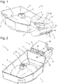
- Fig. 1 and 2 show an evaporative shell assembly 1 in perspective views, which is not part of the invention.
- An approximately rectangular in plan view evaporation tray 2 of the evaporation tray assembly 1 has a bottom 3, in which a central bulge 4 is formed.
- the bulge 4 is shaped to fit tightly to the Top of a (in Fig. 1 not shown) compressor, on which the evaporation tray 2 is placed and to which it is anchored with the aid of formed at the top of the bulge 4 locking clips 5.
- the bottom 3 is surrounded by a circumferential, substantially vertical wall 6.
- a fan housing 7 On a narrow side of this wall 6, a fan housing 7 is arranged. It comprises two of the wall 6 at right angles immovably protruding triangular Fighter plates 8, which are connected at their upper edges to each other by a bottom plate 9.
- the bottom plate 9 is hidden in the assembled state under a cover 10.
- One corner of the lid 10 is in the FIGS. 1 to 3 broken away to give insight into a deflection space 11 between the lid 10 and the bottom plate 9; in Fig. 1 can be seen through the broken corner through an axial fan 12, which at the bottom of the bottom plate 9, below a large-scale central opening 13 (see Fig. 5 ) of the bottom plate 9 is mounted.
- An installation space 14 (see Fig. 5 ), which receives the axial fan 12 is limited by a lower housing part 15.
- a lower housing part 15 At one in the perspective of Fig. 1 the observer facing end wall 16 of the lower housing part 15 are parts of slots 17 can be seen, focusing on a in the Fig. 1 continue invisible oblique edge 18 and together form an intake opening for the axial fan 12.
- the outlet opening 19 is bounded at the bottom by a surge rib 20 whose upper edge is higher than an upper edge 24 of the evaporation shell 2 surrounding wall 6 and which serves to keep the water in the evaporation tray 2 from the axial fan 12, if it is due to a vibration of the refrigerator spilling over.
- Fig. 3 shows the evaporation tray assembly 1 in a partially unfolded configuration.
- the lower housing part 15 is opposite to in Fig. 1 and 2 shown configuration pivoted by 180 ° about an axis 21 which extends along a side facing away from the evaporation tray 2 edge of the bottom plate 9.
- the inclined edge 18 with the slots 17 extending thereon is now fully visible, and the Installation space 14 is open, so that parts of the suspended under the bottom plate 9, flat parallelepiped axial fan 12 can be seen below the viewer facing the fighter plate 8.
- Fig. 4 shows the evaporation tray assembly 1, again in a partially unfolded configuration, in a perspective view from below without the axial fan 12. Clearly visible is the bottom plate 9 with the opening 13 therein. On one of the fighter plates 8 a notch 40 is cut out. A slot 41 is placed in one of the side walls 36 so that it overlaps with the notch 40 in the folded position of the lower housing part and forms a passage for a supply cable of the axial fan 12. Brackets 42, in which the supply cable can be positively locked, are distributed along the wall 6 of the evaporation tray 2.
- Fig. 5 shows a section through the fan housing 7 along in Fig. 1 level designated IV-IV.
- the bottom plate 9 is slightly sloping down to the evaporation cup 2, which is only fragmentarily shown, at an angle of 5-10 °, so that air which is blown by the axial fan 12 in the direction of its axis 22 through the opening 13 of the bottom plate 9 is slightly less must be deflected at 90 ° in order to then sweep horizontally over the water level in the evaporation tray 2.
- the opening 13 may be surrounded by a second surge rib 23 as additional protection against splash water or against condensation, which may be reflected on the walls of the deflection space 11. Since the bottom plate 9 is over its entire extent above the upper edge 24 of the wall 6, it is possible to deduce condensation from the bottom plate 9 in the evaporation tray 2.
- the surge rib 20 may be provided with a narrow passage in the form of a bore or a slot. Although such a narrow passage does not allow appreciable amount of it to pass through during the short time that surge water may be present on the outside of the surge fin 20; However, drops of condensation, which may come from the bottom plate 9 coming forth the surge rib 20 and constantly abut the passage, but this can happen.
- a flat top 25 of the lid 10 is here as the bottom plate 9, albeit at a smaller angle than this, down to the evaporation tray 2 down to condensation, which may be reflected in a rest phase of the axial fan 12 under the lid 10, for draining into Direction of the outlet opening 19 to cause.
- a downwardly directed Abtropfvorsprung 26 is formed at the outlet opening 19 limiting edge of the upper side 25 .
- the drip projection 26 may be in the form of a continuous solid edge, or it may be as shown in FIG Fig. 6 shown to be divided into a plurality of spaced apart along the edge Abtropfnasen. The lowest point of the drip projection 26 should in any case be beyond the surge rib 20, on the side of the evaporation tray 2, so that falling from the projection 26 drops are not prevented by the surge rib 20 from reaching the evaporation tray 2.
- axis 21 about which the lower housing part 15 is pivotable is formed by a film hinge 27 which connects the edge of the bottom plate 9 facing away from the evaporation tray 2 with the end wall 16.
- the lower housing part 15 is secured by latching, for example, as shown here, in which a bottom plate 28 of the housing part 15 engages behind the wall 6 projecting locking lugs 29 and is supported on this.
- Fig. 6 shows a section through the fan housing 7 along in Fig. 5 Level named VI-VI. It can be seen the flat top 25 and two side walls 30, 31 of the lid 10. Between a lower edge of the side wall 31 and one of the fighter plates 8, another film hinge 32 is formed, which supports a 180 ° pivoting movement of the lid 10. In the in Fig. 6 shown closed position, the lid 10 is latched to the bottom plate 9, in the case shown here by means of a latching tongue 33 of the side wall 30, which, as shown, engages in a recess 34 of the adjacent fighter plate 8 or engages around the lower edge.
- the locking tongue 33 passes through a passage 35 of the bottom plate 9 to extend below this in a narrow space between the fighter plate 8 and a side wall 36 of the lower housing part 15.
- the space is so narrow that the latching tongue 33, the recess 34 can not leave.
- the evaporation tray assembly 1 is injection molded from plastic in one piece in a configuration in which both the lid 10 and the lower housing part 15 in the in Fig. 3 are unfolded for the lower housing part 15 shown manner.
- the lid 10 in the position of Fig. 6 folded and fixed by engagement of the latching tongue 33 in the recess 34.
- the axial fan 12 is mounted under the bottom plate 9.
- the installation space 14 around the axial fan 12 is closed by pivoting the lower housing part 15.
- the freedom of movement of the latching tongue 33 is restricted by the side wall 36 so that latching tongue 33, the recess 34 can not leave, that is, the lid 10 is locked.
- the evaporation tray assembly 1 is mounted on a compressor 38 here.
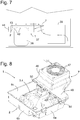
- the axial fan 12 accommodated in the fan housing 7 drives an air flow illustrated by arrows, which flows via a condenser 39 to the fan housing 7 and from there sweeps horizontally across the evaporation tray 2. If compressors 38 are used with different heights, although the position of the evaporation tray assembly 1 in the machine room 37, but not the air flow relative to the water level changes in the evaporation tray 2. Therefore, a constant effectiveness of the evaporation is guaranteed regardless of the model of the compressor 38.
- the fan housing 7 is located at a central location of the machine room 37, far away from all walls.
- the anchored to the brackets 42 of the evaporation tray 2 supply cable 43 connects the hidden in the fan housing 7 axial fan 12 with an arranged on a side wall of the engine room 37 electrical distributor.
- Fig. 8 shows an evaporative shell assembly 1 according to an embodiment of the invention in a perspective view.
- An evaporation tray 2 is as in the case of Fig. 1 in plan view substantially rectangular with four walls 6a, 6b, 6c, 6d, one of which, 6d, in Fig. 8 is not visible.
- a bottom 3 of the evaporation tray 2 has a central bulge 4, which is provided to a compressor in close contact to be put over.
- From the wall 6d of the evaporation tray 2 is an in Fig. 8 not visible plate 45 to the outside (s. Fig. 9 ).
- the plate 45 may be down to the center of the shell 2, so that it is washed over at high water level in the evaporation tray 2 and the water level at which evaporation can take place increased.
- the fan housing 7 which is injection-molded in one piece from plastic, comprises a fan receptacle 46 and a ceiling plate 48.
- the fan receptacle 46 is shaped as a flat block-shaped box open at the bottom and provided with suction slots 47 at its upper side Fig. 9 shown covers a large part of the plate 45 and extends to a small part over the bottom 3 of the evaporation tray 2, and in which an axial fan 12 is mounted with a vertically oriented axis of rotation.
- the ceiling plate 48 extends over the entire depth of the evaporation tray 2, from the wall 6a to the wall 6c. On its underside air guide ribs 49 are formed, whose downstream ends in Fig. 8 are visible. In the embodiment considered here, the air guide ribs 49 are arranged on a strip of the ceiling plate 48, which extends between the fan receptacle 46 and a downstream edge 50 of the ceiling plate 48 from the side wall 6a to the side wall 6c, and extend parallel to each other and in the same length perpendicular to the edge 50.
- the air guide ribs 49 distribute the driven by the fan 12 and deflected in a gap 51 between the fan 12 and the plate 45 and the water level 52 of the evaporation tray 2 in the horizontal air flow evenly over the depth of the evaporation tray 2 and direct him, parallel to the walls 6a, 6c of the evaporation tray 2 are aligned, laminar over the water level 52.
- a water level sensor can be provided on the evaporation tray 2.
Landscapes
- Engineering & Computer Science (AREA)
- Chemical & Material Sciences (AREA)
- Combustion & Propulsion (AREA)
- Physics & Mathematics (AREA)
- Mechanical Engineering (AREA)
- Thermal Sciences (AREA)
- General Engineering & Computer Science (AREA)
- Removal Of Water From Condensation And Defrosting (AREA)
Claims (10)
- Appareil frigorifique avec un condensateur (38) et un module de coque d'évaporation (1) monté sur le condensateur (38), lequel module présente une coque d'évaporation (2) et un support de ventilateur fixé sur la coque d'évaporation (2), dans lequel le support de ventilateur est exécuté sous la forme d'un carter (7) accueillant un ventilateur (12) ou d'une partie d'un carter accueillant le ventilateur (12), caractérisé en ce qu'une plaque de couverture (48) du carter (7) s'étend au-delà de la coque d'évaporation (2), et en ce qu'une partie d'un niveau d'eau (52) de la coque d'évaporation (2) non couverte par le carter de ventilateur (7) est plus grande que la partie couverte.
- Appareil frigorifique selon la revendication 1, caractérisé en ce que le support de ventilateur est formé en une seule pièce avec la coque d'évaporation (2), en particulier via un moulage par injection de plastique.
- Appareil frigorifique selon la revendication 1 ou 2, caractérisé en ce que le support de ventilateur est encliqueté sur la coque d'évaporation (2).
- Appareil frigorifique selon la revendication 1, 2 ou 3, caractérisé en ce que le carter (7) est dimensionné afin d'accueillir un ventilateur axial (12) avec un axe de rotation essentiellement vertical (22).
- Appareil frigorifique selon l'une des revendications précédentes, caractérisé en ce que la plaque de couverture (48) porte des nervures de guidage d'air (49) orientées vers la coque d'évaporation (2).
- Appareil frigorifique selon l'une des revendications précédentes, caractérisé en ce que le ventilateur (12) chevauche la coque d'évaporation (2) en vue du dessus.
- Appareil frigorifique selon l'une des revendications précédentes, caractérisé en ce que le carter (7) présente, entre un espace de montage (14) du ventilateur axial (12) et un orifice de sortie d'air (19), un espace de déviation (51) afin de dévier à l'horizontale le flux d'air mu par le ventilateur axial (12).
- Appareil frigorifique selon la revendication 7, caractérisé en ce que l'espace de déviation (51) est délimité par une plaque de fond (45), à laquelle le ventilateur axial (12) est fixé, et le carter (7) placé sur la plaque de fond (45).
- Appareil frigorifique selon la revendication 8, caractérisé en ce que la plaque de fond (45) est pentue en direction de la coque d'évaporation (2).
- Appareil frigorifique selon l'une des revendications précédentes, caractérisé en ce que la coque d'évaporation (2) présente un fond (3) dans lequel un bombement (4) central est constitué, lequel est formé afin d'épouser étroitement le côté supérieur du condensateur (38).
Priority Applications (1)
| Application Number | Priority Date | Filing Date | Title |
|---|---|---|---|
| PL15157194T PL2927627T3 (pl) | 2014-03-31 | 2015-03-02 | Urządzenie chłodnicze i zespół tac wyparnych do niego |
Applications Claiming Priority (2)
| Application Number | Priority Date | Filing Date | Title |
|---|---|---|---|
| DE102014206085 | 2014-03-31 | ||
| DE102014222258.3A DE102014222258A1 (de) | 2014-03-31 | 2014-10-31 | Kältegerät und Verdunstungsschalenbaugruppe dafür |
Publications (2)
| Publication Number | Publication Date |
|---|---|
| EP2927627A1 EP2927627A1 (fr) | 2015-10-07 |
| EP2927627B1 true EP2927627B1 (fr) | 2018-05-30 |
Family
ID=52598620
Family Applications (1)
| Application Number | Title | Priority Date | Filing Date |
|---|---|---|---|
| EP15157194.0A Active EP2927627B1 (fr) | 2014-03-31 | 2015-03-02 | Appareil frigorifique et composant de coque d'évaporation correspondant |
Country Status (4)
| Country | Link |
|---|---|
| EP (1) | EP2927627B1 (fr) |
| DE (1) | DE102014222258A1 (fr) |
| PL (1) | PL2927627T3 (fr) |
| TR (1) | TR201809768T4 (fr) |
Families Citing this family (1)
| Publication number | Priority date | Publication date | Assignee | Title |
|---|---|---|---|---|
| DE102023201153A1 (de) * | 2023-02-13 | 2024-08-14 | BSH Hausgeräte GmbH | Kältegerät und Verdunstungseinrichtung für ein Kältegerät |
Family Cites Families (5)
| Publication number | Priority date | Publication date | Assignee | Title |
|---|---|---|---|---|
| KR100333624B1 (ko) * | 2000-03-20 | 2002-04-22 | 구자홍 | 냉장고의 기계실 팬가이드 장착구조 |
| JP5011905B2 (ja) * | 2006-02-01 | 2012-08-29 | パナソニック株式会社 | 冷蔵庫 |
| JP2009030864A (ja) * | 2007-07-26 | 2009-02-12 | Hitachi Appliances Inc | 冷蔵庫 |
| JP5534717B2 (ja) * | 2009-06-04 | 2014-07-02 | 三菱電機株式会社 | 蒸発装置 |
| JP5402727B2 (ja) * | 2010-03-05 | 2014-01-29 | パナソニック株式会社 | 冷蔵庫 |
-
2014
- 2014-10-31 DE DE102014222258.3A patent/DE102014222258A1/de not_active Withdrawn
-
2015
- 2015-03-02 TR TR2018/09768T patent/TR201809768T4/tr unknown
- 2015-03-02 EP EP15157194.0A patent/EP2927627B1/fr active Active
- 2015-03-02 PL PL15157194T patent/PL2927627T3/pl unknown
Non-Patent Citations (1)
| Title |
|---|
| None * |
Also Published As
| Publication number | Publication date |
|---|---|
| EP2927627A1 (fr) | 2015-10-07 |
| DE102014222258A1 (de) | 2015-10-01 |
| TR201809768T4 (tr) | 2018-07-23 |
| PL2927627T3 (pl) | 2018-10-31 |
Similar Documents
| Publication | Publication Date | Title |
|---|---|---|
| DE19609687C2 (de) | Wandkühlgerät für einen Schaltsschrank mit einem Lüfter und einem Lamellen-Wärmetauscher | |
| EP0190794A2 (fr) | Réfrigérateur encastré | |
| DE19734146C2 (de) | Luftzuführeinrichtung | |
| EP2678623B1 (fr) | Appareil frigorifique comportant une coquille d'évaporation | |
| WO2004001306A1 (fr) | Ensemble cuvette d'evaporation-compresseur pour appareil de refrigeration | |
| EP2160553A1 (fr) | Appareil frigorifique comportant un groupe de ventilation | |
| DE102009059836A1 (de) | Filtereinheit für eine Dunstabzugshaube und Dunstabzugshaube | |
| EP2697578B1 (fr) | Appareil frigorifique comportant un bac d'évaporation | |
| EP1119230A2 (fr) | Dispositif de refroidissement | |
| DE102009056426A1 (de) | Unterbaugruppenelement für ein Kühl- und/oder Gefriergerät, Kühl- und/oder Gefriergerät sowie Verfahren zur Montage eines Kühl- und/oder Gefriergerätes | |
| DE102017213972A1 (de) | Kältegerät mit Verdunstungsschale | |
| DE102010013639A1 (de) | Kühlaggregat für Schaltschränke | |
| EP2927627A1 (fr) | Appareil frigorifique et composant de coque d'évaporation correspondant | |
| DE8210690U1 (de) | Einbaugerät, insbesondere in eine Küchenzeile einbaubarer Kühl- oder Gefrierschrank | |
| EP1520138B1 (fr) | Appareil frigorifique a bac d'evaporation | |
| DE102005021560A1 (de) | Kältegerät mit Umluftkühlung | |
| EP1934541B1 (fr) | Plateau de stockage pour un appareil de refrigeration | |
| DE102009000852B4 (de) | Kältegerät mit innenliegendem Verdampfer | |
| DE102005021535A1 (de) | Kältegerät mit Umluftkühlung | |
| EP2419687B1 (fr) | Appareil frigorifique sans givre | |
| DE102008054995A1 (de) | Kältegerät mit Luftfilter | |
| EP2691711B1 (fr) | Appareil frigorifique à ventilateur axial | |
| EP2426446A2 (fr) | Appareil frigorifique encastrable | |
| EP2433067B1 (fr) | Appareil frigorifique à évacuation d'eau de condensation | |
| EP4348134A1 (fr) | Appareil frigorifique ménager doté d'un élément de paroi pourvu d'un film estampé à chaud |
Legal Events
| Date | Code | Title | Description |
|---|---|---|---|
| PUAI | Public reference made under article 153(3) epc to a published international application that has entered the european phase |
Free format text: ORIGINAL CODE: 0009012 |
|
| AK | Designated contracting states |
Kind code of ref document: A1 Designated state(s): AL AT BE BG CH CY CZ DE DK EE ES FI FR GB GR HR HU IE IS IT LI LT LU LV MC MK MT NL NO PL PT RO RS SE SI SK SM TR |
|
| AX | Request for extension of the european patent |
Extension state: BA ME |
|
| 17P | Request for examination filed |
Effective date: 20160407 |
|
| RBV | Designated contracting states (corrected) |
Designated state(s): AL AT BE BG CH CY CZ DE DK EE ES FI FR GB GR HR HU IE IS IT LI LT LU LV MC MK MT NL NO PL PT RO RS SE SI SK SM TR |
|
| STAA | Information on the status of an ep patent application or granted ep patent |
Free format text: STATUS: EXAMINATION IS IN PROGRESS |
|
| 17Q | First examination report despatched |
Effective date: 20170407 |
|
| GRAP | Despatch of communication of intention to grant a patent |
Free format text: ORIGINAL CODE: EPIDOSNIGR1 |
|
| STAA | Information on the status of an ep patent application or granted ep patent |
Free format text: STATUS: GRANT OF PATENT IS INTENDED |
|
| INTG | Intention to grant announced |
Effective date: 20171207 |
|
| GRAS | Grant fee paid |
Free format text: ORIGINAL CODE: EPIDOSNIGR3 |
|
| GRAA | (expected) grant |
Free format text: ORIGINAL CODE: 0009210 |
|
| STAA | Information on the status of an ep patent application or granted ep patent |
Free format text: STATUS: THE PATENT HAS BEEN GRANTED |
|
| AK | Designated contracting states |
Kind code of ref document: B1 Designated state(s): AL AT BE BG CH CY CZ DE DK EE ES FI FR GB GR HR HU IE IS IT LI LT LU LV MC MK MT NL NO PL PT RO RS SE SI SK SM TR |
|
| REG | Reference to a national code |
Ref country code: GB Ref legal event code: FG4D Free format text: NOT ENGLISH |
|
| REG | Reference to a national code |
Ref country code: CH Ref legal event code: EP |
|
| REG | Reference to a national code |
Ref country code: AT Ref legal event code: REF Ref document number: 1004030 Country of ref document: AT Kind code of ref document: T Effective date: 20180615 |
|
| REG | Reference to a national code |
Ref country code: DE Ref legal event code: R096 Ref document number: 502015004426 Country of ref document: DE |
|
| REG | Reference to a national code |
Ref country code: IE Ref legal event code: FG4D Free format text: LANGUAGE OF EP DOCUMENT: GERMAN |
|
| REG | Reference to a national code |
Ref country code: NL Ref legal event code: MP Effective date: 20180530 |
|
| REG | Reference to a national code |
Ref country code: LT Ref legal event code: MG4D |
|
| PG25 | Lapsed in a contracting state [announced via postgrant information from national office to epo] |
Ref country code: SE Free format text: LAPSE BECAUSE OF FAILURE TO SUBMIT A TRANSLATION OF THE DESCRIPTION OR TO PAY THE FEE WITHIN THE PRESCRIBED TIME-LIMIT Effective date: 20180530 Ref country code: LT Free format text: LAPSE BECAUSE OF FAILURE TO SUBMIT A TRANSLATION OF THE DESCRIPTION OR TO PAY THE FEE WITHIN THE PRESCRIBED TIME-LIMIT Effective date: 20180530 Ref country code: ES Free format text: LAPSE BECAUSE OF FAILURE TO SUBMIT A TRANSLATION OF THE DESCRIPTION OR TO PAY THE FEE WITHIN THE PRESCRIBED TIME-LIMIT Effective date: 20180530 Ref country code: NO Free format text: LAPSE BECAUSE OF FAILURE TO SUBMIT A TRANSLATION OF THE DESCRIPTION OR TO PAY THE FEE WITHIN THE PRESCRIBED TIME-LIMIT Effective date: 20180830 Ref country code: CY Free format text: LAPSE BECAUSE OF FAILURE TO SUBMIT A TRANSLATION OF THE DESCRIPTION OR TO PAY THE FEE WITHIN THE PRESCRIBED TIME-LIMIT Effective date: 20180530 Ref country code: FI Free format text: LAPSE BECAUSE OF FAILURE TO SUBMIT A TRANSLATION OF THE DESCRIPTION OR TO PAY THE FEE WITHIN THE PRESCRIBED TIME-LIMIT Effective date: 20180530 Ref country code: BG Free format text: LAPSE BECAUSE OF FAILURE TO SUBMIT A TRANSLATION OF THE DESCRIPTION OR TO PAY THE FEE WITHIN THE PRESCRIBED TIME-LIMIT Effective date: 20180830 |
|
| PG25 | Lapsed in a contracting state [announced via postgrant information from national office to epo] |
Ref country code: RS Free format text: LAPSE BECAUSE OF FAILURE TO SUBMIT A TRANSLATION OF THE DESCRIPTION OR TO PAY THE FEE WITHIN THE PRESCRIBED TIME-LIMIT Effective date: 20180530 Ref country code: LV Free format text: LAPSE BECAUSE OF FAILURE TO SUBMIT A TRANSLATION OF THE DESCRIPTION OR TO PAY THE FEE WITHIN THE PRESCRIBED TIME-LIMIT Effective date: 20180530 Ref country code: GR Free format text: LAPSE BECAUSE OF FAILURE TO SUBMIT A TRANSLATION OF THE DESCRIPTION OR TO PAY THE FEE WITHIN THE PRESCRIBED TIME-LIMIT Effective date: 20180831 Ref country code: HR Free format text: LAPSE BECAUSE OF FAILURE TO SUBMIT A TRANSLATION OF THE DESCRIPTION OR TO PAY THE FEE WITHIN THE PRESCRIBED TIME-LIMIT Effective date: 20180530 |
|
| PG25 | Lapsed in a contracting state [announced via postgrant information from national office to epo] |
Ref country code: NL Free format text: LAPSE BECAUSE OF FAILURE TO SUBMIT A TRANSLATION OF THE DESCRIPTION OR TO PAY THE FEE WITHIN THE PRESCRIBED TIME-LIMIT Effective date: 20180530 |
|
| PG25 | Lapsed in a contracting state [announced via postgrant information from national office to epo] |
Ref country code: DK Free format text: LAPSE BECAUSE OF FAILURE TO SUBMIT A TRANSLATION OF THE DESCRIPTION OR TO PAY THE FEE WITHIN THE PRESCRIBED TIME-LIMIT Effective date: 20180530 Ref country code: SK Free format text: LAPSE BECAUSE OF FAILURE TO SUBMIT A TRANSLATION OF THE DESCRIPTION OR TO PAY THE FEE WITHIN THE PRESCRIBED TIME-LIMIT Effective date: 20180530 Ref country code: EE Free format text: LAPSE BECAUSE OF FAILURE TO SUBMIT A TRANSLATION OF THE DESCRIPTION OR TO PAY THE FEE WITHIN THE PRESCRIBED TIME-LIMIT Effective date: 20180530 Ref country code: RO Free format text: LAPSE BECAUSE OF FAILURE TO SUBMIT A TRANSLATION OF THE DESCRIPTION OR TO PAY THE FEE WITHIN THE PRESCRIBED TIME-LIMIT Effective date: 20180530 Ref country code: CZ Free format text: LAPSE BECAUSE OF FAILURE TO SUBMIT A TRANSLATION OF THE DESCRIPTION OR TO PAY THE FEE WITHIN THE PRESCRIBED TIME-LIMIT Effective date: 20180530 |
|
| PG25 | Lapsed in a contracting state [announced via postgrant information from national office to epo] |
Ref country code: SM Free format text: LAPSE BECAUSE OF FAILURE TO SUBMIT A TRANSLATION OF THE DESCRIPTION OR TO PAY THE FEE WITHIN THE PRESCRIBED TIME-LIMIT Effective date: 20180530 |
|
| REG | Reference to a national code |
Ref country code: DE Ref legal event code: R097 Ref document number: 502015004426 Country of ref document: DE |
|
| PLBE | No opposition filed within time limit |
Free format text: ORIGINAL CODE: 0009261 |
|
| STAA | Information on the status of an ep patent application or granted ep patent |
Free format text: STATUS: NO OPPOSITION FILED WITHIN TIME LIMIT |
|
| 26N | No opposition filed |
Effective date: 20190301 |
|
| PG25 | Lapsed in a contracting state [announced via postgrant information from national office to epo] |
Ref country code: SI Free format text: LAPSE BECAUSE OF FAILURE TO SUBMIT A TRANSLATION OF THE DESCRIPTION OR TO PAY THE FEE WITHIN THE PRESCRIBED TIME-LIMIT Effective date: 20180530 |
|
| PG25 | Lapsed in a contracting state [announced via postgrant information from national office to epo] |
Ref country code: MC Free format text: LAPSE BECAUSE OF FAILURE TO SUBMIT A TRANSLATION OF THE DESCRIPTION OR TO PAY THE FEE WITHIN THE PRESCRIBED TIME-LIMIT Effective date: 20180530 |
|
| REG | Reference to a national code |
Ref country code: CH Ref legal event code: PL |
|
| GBPC | Gb: european patent ceased through non-payment of renewal fee |
Effective date: 20190302 |
|
| PG25 | Lapsed in a contracting state [announced via postgrant information from national office to epo] |
Ref country code: LU Free format text: LAPSE BECAUSE OF NON-PAYMENT OF DUE FEES Effective date: 20190302 Ref country code: AL Free format text: LAPSE BECAUSE OF FAILURE TO SUBMIT A TRANSLATION OF THE DESCRIPTION OR TO PAY THE FEE WITHIN THE PRESCRIBED TIME-LIMIT Effective date: 20180530 |
|
| REG | Reference to a national code |
Ref country code: BE Ref legal event code: MM Effective date: 20190331 |
|
| PG25 | Lapsed in a contracting state [announced via postgrant information from national office to epo] |
Ref country code: IE Free format text: LAPSE BECAUSE OF NON-PAYMENT OF DUE FEES Effective date: 20190302 Ref country code: GB Free format text: LAPSE BECAUSE OF NON-PAYMENT OF DUE FEES Effective date: 20190302 Ref country code: LI Free format text: LAPSE BECAUSE OF NON-PAYMENT OF DUE FEES Effective date: 20190331 Ref country code: CH Free format text: LAPSE BECAUSE OF NON-PAYMENT OF DUE FEES Effective date: 20190331 |
|
| PG25 | Lapsed in a contracting state [announced via postgrant information from national office to epo] |
Ref country code: FR Free format text: LAPSE BECAUSE OF NON-PAYMENT OF DUE FEES Effective date: 20190331 Ref country code: BE Free format text: LAPSE BECAUSE OF NON-PAYMENT OF DUE FEES Effective date: 20190331 |
|
| PGFP | Annual fee paid to national office [announced via postgrant information from national office to epo] |
Ref country code: IT Payment date: 20200325 Year of fee payment: 6 |
|
| PG25 | Lapsed in a contracting state [announced via postgrant information from national office to epo] |
Ref country code: PT Free format text: LAPSE BECAUSE OF FAILURE TO SUBMIT A TRANSLATION OF THE DESCRIPTION OR TO PAY THE FEE WITHIN THE PRESCRIBED TIME-LIMIT Effective date: 20181001 Ref country code: MT Free format text: LAPSE BECAUSE OF FAILURE TO SUBMIT A TRANSLATION OF THE DESCRIPTION OR TO PAY THE FEE WITHIN THE PRESCRIBED TIME-LIMIT Effective date: 20180530 |
|
| REG | Reference to a national code |
Ref country code: AT Ref legal event code: MM01 Ref document number: 1004030 Country of ref document: AT Kind code of ref document: T Effective date: 20200302 |
|
| PG25 | Lapsed in a contracting state [announced via postgrant information from national office to epo] |
Ref country code: IS Free format text: LAPSE BECAUSE OF FAILURE TO SUBMIT A TRANSLATION OF THE DESCRIPTION OR TO PAY THE FEE WITHIN THE PRESCRIBED TIME-LIMIT Effective date: 20180930 |
|
| PG25 | Lapsed in a contracting state [announced via postgrant information from national office to epo] |
Ref country code: HU Free format text: LAPSE BECAUSE OF FAILURE TO SUBMIT A TRANSLATION OF THE DESCRIPTION OR TO PAY THE FEE WITHIN THE PRESCRIBED TIME-LIMIT; INVALID AB INITIO Effective date: 20150302 |
|
| PG25 | Lapsed in a contracting state [announced via postgrant information from national office to epo] |
Ref country code: AT Free format text: LAPSE BECAUSE OF NON-PAYMENT OF DUE FEES Effective date: 20200302 |
|
| PG25 | Lapsed in a contracting state [announced via postgrant information from national office to epo] |
Ref country code: IT Free format text: LAPSE BECAUSE OF NON-PAYMENT OF DUE FEES Effective date: 20210302 |
|
| PGFP | Annual fee paid to national office [announced via postgrant information from national office to epo] |
Ref country code: DE Payment date: 20220331 Year of fee payment: 8 |
|
| PGFP | Annual fee paid to national office [announced via postgrant information from national office to epo] |
Ref country code: TR Payment date: 20220218 Year of fee payment: 8 Ref country code: PL Payment date: 20220221 Year of fee payment: 8 |
|
| PG25 | Lapsed in a contracting state [announced via postgrant information from national office to epo] |
Ref country code: MK Free format text: LAPSE BECAUSE OF FAILURE TO SUBMIT A TRANSLATION OF THE DESCRIPTION OR TO PAY THE FEE WITHIN THE PRESCRIBED TIME-LIMIT Effective date: 20180530 |
|
| REG | Reference to a national code |
Ref country code: DE Ref legal event code: R119 Ref document number: 502015004426 Country of ref document: DE |
|
| PG25 | Lapsed in a contracting state [announced via postgrant information from national office to epo] |
Ref country code: DE Free format text: LAPSE BECAUSE OF NON-PAYMENT OF DUE FEES Effective date: 20231003 |
|
| PG25 | Lapsed in a contracting state [announced via postgrant information from national office to epo] |
Ref country code: PL Free format text: LAPSE BECAUSE OF NON-PAYMENT OF DUE FEES Effective date: 20230302 |
|
| PG25 | Lapsed in a contracting state [announced via postgrant information from national office to epo] |
Ref country code: PL Free format text: LAPSE BECAUSE OF NON-PAYMENT OF DUE FEES Effective date: 20230302 |