EP2927661A2 - Actionneur - Google Patents
Actionneur Download PDFInfo
- Publication number
- EP2927661A2 EP2927661A2 EP14001657.7A EP14001657A EP2927661A2 EP 2927661 A2 EP2927661 A2 EP 2927661A2 EP 14001657 A EP14001657 A EP 14001657A EP 2927661 A2 EP2927661 A2 EP 2927661A2
- Authority
- EP
- European Patent Office
- Prior art keywords
- actuator
- housing
- shaft
- coupling rods
- actuator according
- Prior art date
- Legal status (The legal status is an assumption and is not a legal conclusion. Google has not performed a legal analysis and makes no representation as to the accuracy of the status listed.)
- Withdrawn
Links
- 230000008878 coupling Effects 0.000 claims abstract description 37
- 238000010168 coupling process Methods 0.000 claims abstract description 37
- 238000005859 coupling reaction Methods 0.000 claims abstract description 37
- 238000012360 testing method Methods 0.000 claims abstract description 19
- 230000005284 excitation Effects 0.000 claims abstract description 16
- 230000010355 oscillation Effects 0.000 claims abstract description 15
- 230000005540 biological transmission Effects 0.000 claims abstract description 10
- 238000005452 bending Methods 0.000 abstract description 6
- 230000033001 locomotion Effects 0.000 description 4
- 230000015572 biosynthetic process Effects 0.000 description 1
- 150000001875 compounds Chemical class 0.000 description 1
- 230000003993 interaction Effects 0.000 description 1
- 238000010079 rubber tapping Methods 0.000 description 1
Images


Classifications
-
- G—PHYSICS
- G01—MEASURING; TESTING
- G01M—TESTING STATIC OR DYNAMIC BALANCE OF MACHINES OR STRUCTURES; TESTING OF STRUCTURES OR APPARATUS, NOT OTHERWISE PROVIDED FOR
- G01M7/00—Vibration-testing of structures; Shock-testing of structures
- G01M7/02—Vibration-testing by means of a shake table
- G01M7/027—Specimen mounting arrangements, e.g. table head adapters
-
- G—PHYSICS
- G01—MEASURING; TESTING
- G01M—TESTING STATIC OR DYNAMIC BALANCE OF MACHINES OR STRUCTURES; TESTING OF STRUCTURES OR APPARATUS, NOT OTHERWISE PROVIDED FOR
- G01M7/00—Vibration-testing of structures; Shock-testing of structures
- G01M7/02—Vibration-testing by means of a shake table
- G01M7/06—Multidirectional test stands
Definitions
- the invention relates to an actuator for generating an exciter oscillation for a vibration system, in particular a resonance test rig for verifying the circumferential bending in rotational test specimens.
- At least three coupling rods arranged uniformly over a circumference about the axis of rotation of the test object are provided, which are coupled, on the one hand, with an actuator, on the other hand with the test object, essentially without play.
- the ends of the coupling rods are secured in a play-free manner by means of a torsionally flexible and flexurally elastic joining connection such that the test specimen is preferably set in vibration at or near its resonance frequency.
- the selected over a circumference around the axis of rotation of the specimen arrangement of the coupling rods is thereby a to the fixed axis of rotation of the specimen according to the exciter frequency circulating moment exerted.
- the present invention has for its object to provide an actuator for a resonance test, which manages with minimal excitation forces in the generation and transmission of the excitation oscillation and wherein by a suitable structural design of the actuator, both the generation and the transmission of the exciter oscillation on particularly effective Way are guaranteed.
- three or more coupling rods or a multiple thereof may be provided, which are arranged rotationally symmetrical with respect to the axis of rotation of the specimen.
- four coupling rods are used from the viewpoint of technical and economic efficiency, which are arranged offset in the circumferential direction by 90 ° to each other.
- the coupling rods are fastened at their ends in each case in or near the plane of the respective zero deformation point of the oscillation within the scope of the invention proposal; in the training of Fixing points is to be noted that these actuator side are designed essentially as a backlash-free, torsionally and / or flexible elastic joint connection.
- coupling rods according to the invention as transmission elements of the excitation oscillation enables a targeted arrangement of their force application in such a way that the oscillation system acts in the dynamic deformation zero point of the resonant connection part, either an actuator or a test object. Since in this way no vibration energy is lost to the environment, provided with actuators according to the invention resonant test rig altogether with small excitation forces and low energy work.
- An advantageous embodiment of the actuator according to the invention consists in that it comprises an actuator housing mounted on a rotationally drivable exciter shaft with eccentric masses displaced thereon in such a way that it forms a vibration system with the rotating exciter shaft and that the attachment points of the coupling rods are assigned to the actuator housing.
- the excitation vibration generated in the actuator is transmitted to the actuator housing and transmitted from there by means of the attachment points of the coupling rods on the latter and of these further on the specimen.
- this results in vibration amplitudes in the millimeter range in the axial direction of the coupling bars and in ⁇ -Meter Scheme in the radial direction of the coupling bars, depending on the configuration of the actuator, for example of 3 mm axially and 3 ⁇ m radially.
- the exciter shaft located in the interior of the actuator housing carries a pair of eccentric masses, which are offset from one another by 180 °.
- the amplitude of the excitation oscillation can be varied by the dimensioning and arrangement of the eccentric masses.
- the exciter shaft as a hollow shaft is formed and rotatably connected to an internal drive shaft and limited to this movable.
- the transmission of the rotational movement of the drive shaft to the exciter shaft is advantageously designed according to a further proposal according to the invention that the ends of the exciter shaft are mounted in opposite end walls of the actuator and that the exciter shaft connected in the middle between their ends via a gimbal joint with the drive axle is.
- the actuator housing is formed substantially cylindrical and that the attachment points of the ends of the coupling rods are distributed on the outside of the actuator housing in the housing longitudinal plane perpendicular to the housing longitudinal axis evenly over the housing circumference.
- the housing center plane is chosen so that it is located in the middle between the two eccentric masses and thus in the dynamic zero point of the exciter shaft.
- the actuator housing in the housing center plane has a circumferential, outwardly projecting annular bracket, on which fastening elements for attachment of the associated ends of the coupling rods are provided.
- the exciter shaft is preferably mounted by means of pendulum bearings to the transmission of excitation forces on the actuator as unhindered to ensure.
- a vibration system which allows the actuator side training and tapping an exciter vibration in largely undisturbed expression.
- the reason for this is the interaction of several design features that significantly influence the generation of the exciter oscillation. These include on the one hand the drive transmission to the exciter shaft by being designed as a hollow shaft and is advantageously coupled via a universal joint with the drive shaft, and the oscillating mounting of the actuator on the exciter shaft, also the equipping of the exciter shaft with eccentric masses, with respect to the housing center plane symmetrical are staggered, and finally the design of the Connection of the attachment points for the associated ends of the coupling rods in the housing center plane on the outside of the actuator housing.
- Fig. 1 shows an actuator for generating an excitation vibration for vibration systems, in this case for use in a resonance test stand.
- a cylindrical actuator housing 1 is shown inside the housing.
- a drive axle 2 is mounted within an exciter shaft 3 designed as a hollow shaft.
- an exciter shaft 3 designed as a hollow shaft.
- a cardan joint is provided inside the housing; It has short connecting pins 4 between a joint outer ring 5 and the exciter shaft 3 and a diagonal continuous connecting pin 6 between the outer race 5 and the drive axle 2.
- the torque of the drive shaft 2 is transmitted via the mounted in a bearing sleeve 9 in the outer joint ring 5 diagonal connecting pin 6 and introduced by the short connecting pin 4 from the outer race 5 in the exciter shaft 3, which has holes 7 for the free passage of the diagonal connecting pin 6.
- pendulum bearing 90 which are arranged in opposite end faces 10 of the Aktuatorgenäuses 1. In this way, it is ensured that the eccentric forces of the exciter shaft 3 can be introduced into the actuator housing 1 and forwarded therefrom.
- Fig. 2 shows a longitudinal section through the actuator housing in the plane II-II according to Fig. 1 ,
- the laterally projecting ends of the drive axle 2 via the actuator housing 1 are mounted in bearing blocks 19 in axial / radial roller bearings 18.
- the drive shaft 2 is rotatably connected to a drive gear 20.
- the associated ends of the coupling rods 12 are formed in a special way.
- the bending-resistant tube sleeve of the coupling rods 12 ends with a bending rod 22 connected between transverse walls 21, the length of which, for example, amounts to 20% of the total length of a coupling rod 12.
- the bending rod 22 is fixedly connected with a press fit with a support member 23 of the foot part 13, so that it is free of play but limited elastic connected to this attachment point. Thanks to this elasticity, there is the possibility of forwarding the exciter vibration in the coupling rod 12 and of this over a further (not shown) attachment point in the test specimen of the resonance test bench.
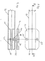
- the support member 23 extends with little clearance through a passage opening 24 of the coupling rod 12 forming tubular sleeve, as can be seen in Fig. 3 can recognize.
- Fig. 4 shows the connection point according to Fig. 3 in plan view, namely the coupling rod 12, the foot part 13 and the holes 25 provided therein for in Fig. 1 drawn screws 14 for fixing the foot part 13 on the supports 15 of the ring console eleventh
Landscapes
- Physics & Mathematics (AREA)
- General Physics & Mathematics (AREA)
- Investigating Strength Of Materials By Application Of Mechanical Stress (AREA)
- Vibration Prevention Devices (AREA)
- Apparatuses For Generation Of Mechanical Vibrations (AREA)
Priority Applications (1)
| Application Number | Priority Date | Filing Date | Title |
|---|---|---|---|
| EP14001657.7A EP2927661A3 (fr) | 2014-04-04 | 2014-05-12 | Actionneur |
Applications Claiming Priority (2)
| Application Number | Priority Date | Filing Date | Title |
|---|---|---|---|
| EP14001257.6A EP2927660B1 (fr) | 2014-04-04 | 2014-04-04 | Dispositif d'essai de charge d'échantillons rotatifs |
| EP14001657.7A EP2927661A3 (fr) | 2014-04-04 | 2014-05-12 | Actionneur |
Publications (2)
| Publication Number | Publication Date |
|---|---|
| EP2927661A2 true EP2927661A2 (fr) | 2015-10-07 |
| EP2927661A3 EP2927661A3 (fr) | 2015-10-28 |
Family
ID=50442317
Family Applications (3)
| Application Number | Title | Priority Date | Filing Date |
|---|---|---|---|
| EP14001257.6A Active EP2927660B1 (fr) | 2014-04-04 | 2014-04-04 | Dispositif d'essai de charge d'échantillons rotatifs |
| EP14001659.3A Not-in-force EP2930490B1 (fr) | 2014-04-04 | 2014-05-12 | Élément de liaison destiné au transfert d'une vibration de source dans un système vibratoire |
| EP14001657.7A Withdrawn EP2927661A3 (fr) | 2014-04-04 | 2014-05-12 | Actionneur |
Family Applications Before (2)
| Application Number | Title | Priority Date | Filing Date |
|---|---|---|---|
| EP14001257.6A Active EP2927660B1 (fr) | 2014-04-04 | 2014-04-04 | Dispositif d'essai de charge d'échantillons rotatifs |
| EP14001659.3A Not-in-force EP2930490B1 (fr) | 2014-04-04 | 2014-05-12 | Élément de liaison destiné au transfert d'une vibration de source dans un système vibratoire |
Country Status (1)
| Country | Link |
|---|---|
| EP (3) | EP2927660B1 (fr) |
Families Citing this family (16)
| Publication number | Priority date | Publication date | Assignee | Title |
|---|---|---|---|---|
| CN105910780B (zh) * | 2016-04-06 | 2018-04-10 | 重庆大学 | 一种精确可控非接触试件旋转式磁场疲劳激振与测振装置 |
| AT518412B1 (de) * | 2016-06-07 | 2017-10-15 | Prisma Eng Maschinen- Und Motorentechnik Gmbh | Schwinglast, Prüfstand zum Schwingungsprüfen und Verfahren hiefür |
| CN106370370B (zh) * | 2016-08-17 | 2019-01-25 | 中国航空工业集团公司西安飞行自动控制研究所 | 一种可快速转换的作动器振动试验夹具 |
| FR3057955A1 (fr) | 2016-10-21 | 2018-04-27 | Mg-Valdunes | Appareil pour tester un arbre et/ou une piece mecanique montee sur l'arbre et utilisation d'un tel appareil |
| CN106636609B (zh) * | 2017-01-20 | 2018-06-01 | 广西大学 | 一种凸轮冲击式交变力矩弯扭耦合共振式振动时效装置 |
| CN106702136B (zh) * | 2017-01-20 | 2018-06-05 | 广西大学 | 圆柱凸轮激励引发的弯扭耦合共振式残余应力消除装置 |
| CN106702135B (zh) * | 2017-01-20 | 2018-06-01 | 广西大学 | 一种由偏心电机激发的弯扭耦合共振式残余应力消除装置 |
| CN106636608B (zh) * | 2017-01-20 | 2018-06-05 | 广西大学 | 一种由电磁致动器激发的弯扭耦合共振式振动时效装置 |
| CN107290435B (zh) * | 2017-06-08 | 2020-03-03 | 浙江理工大学 | 一种用于旋转主轴裂纹检测的弹性波激发装置 |
| CN107388907A (zh) * | 2017-08-22 | 2017-11-24 | 天津航天瑞莱科技有限公司 | 一种导弹自转状态下的自由模态试验系统 |
| NL2020815B1 (en) * | 2018-04-24 | 2019-10-31 | Onderzoekscentrum Voor Aanwending Van Staal N V | Resonant fatigue testing |
| CN109855800A (zh) * | 2019-03-29 | 2019-06-07 | 国网山东省电力公司电力科学研究院 | 降低汽轮机转子残余应力释放引起的开机异常振动的方法 |
| CN111323197B (zh) * | 2020-03-25 | 2024-06-14 | 安徽三联学院 | 一种飞机轴系冲击振动模拟试验装置及其使用方法 |
| CN111829802B (zh) * | 2020-06-12 | 2024-07-30 | 江苏大学 | 一种多滚筒动平衡振动耦合试验台及试验方法 |
| CN117871001B (zh) * | 2023-12-18 | 2024-07-23 | 中国科学院空间应用工程与技术中心 | 一种实验舱导向机构用滚轮的动态振动测试装置 |
| CN118837032B (zh) * | 2024-09-24 | 2024-12-13 | 潍坊学院 | 一种基于振动测试的锥箱故障诊断装置及方法 |
Family Cites Families (7)
| Publication number | Priority date | Publication date | Assignee | Title |
|---|---|---|---|---|
| US2228499A (en) * | 1936-12-30 | 1941-01-14 | Bosch Gmbh Robert | Apparatus for the vibration testing of articles |
| DE2601259C3 (de) | 1976-01-15 | 1979-03-29 | Fraunhofer-Gesellschaft Zur Foerderung Der Angewandten Forschung E.V., 8000 Muenchen | Einrichtung zur betriebsähnlichen Prüfung von Radsätzen |
| US6035715A (en) * | 1997-09-15 | 2000-03-14 | Entela, Inc, | Method and apparatus for optimizing the design of a product |
| US6247366B1 (en) * | 1997-09-15 | 2001-06-19 | Alexander J. Porter | Design maturity algorithm |
| US7013731B1 (en) * | 2004-10-15 | 2006-03-21 | Western Digital Technologies, Inc. | Data storage testing apparatus for delivering linear or rotational acceleration |
| DE102010027897B4 (de) | 2010-04-19 | 2013-02-28 | Sven Henze | Schwingungsprüfeinrichtung |
| ES2363549B1 (es) * | 2011-03-08 | 2012-03-23 | Instituto Tecnológico Del Embalaje, Transporte Y Log�?Stica | M�?quina simuladora de movimiento producido durante el transporte |
-
2014
- 2014-04-04 EP EP14001257.6A patent/EP2927660B1/fr active Active
- 2014-05-12 EP EP14001659.3A patent/EP2930490B1/fr not_active Not-in-force
- 2014-05-12 EP EP14001657.7A patent/EP2927661A3/fr not_active Withdrawn
Non-Patent Citations (1)
| Title |
|---|
| None |
Also Published As
| Publication number | Publication date |
|---|---|
| EP2927660A1 (fr) | 2015-10-07 |
| EP2930490A1 (fr) | 2015-10-14 |
| EP2930490B1 (fr) | 2016-05-25 |
| EP2927660B1 (fr) | 2016-10-12 |
| EP2927661A3 (fr) | 2015-10-28 |
Similar Documents
| Publication | Publication Date | Title |
|---|---|---|
| EP2927661A2 (fr) | Actionneur | |
| EP1998930B1 (fr) | Dispositif de positionnement | |
| EP1336478A2 (fr) | Organe d'entraínement d'un composant rotatif faisant partie d'une machine à imprimer | |
| EP2428788B1 (fr) | Dispositif de palier de pivotement d'un rotor devant être équilibré | |
| DD223204A5 (de) | Kopplungsvorrichtung fuer mit kleinen ausschlaegen schwingende wellen | |
| DE3716215C2 (fr) | ||
| EP4526563B1 (fr) | Carter de boîte de vitesses monté sur ressort | |
| EP2732100B1 (fr) | Excitateur à balourd pour compacteur de sol | |
| DE102010017455B4 (de) | Vorrichtung und Verfahren zur Prüfung der Betriebsfestigkeit eines Körpers | |
| DD217294A5 (de) | Spielfrei einstellbarer schwenkantrieb fuer mindestens eine hauptachse von manipulatoren | |
| DE69208440T2 (de) | Zylindrische Elastomer-Lager-Anlage mit grossem WInkelausschlag | |
| DE102005021459B3 (de) | Mechanischer Rotationsantrieb | |
| WO2017081032A1 (fr) | Ensemble de propulsion pour un véhicule ferroviaire, véhicule ferroviaire comprenant l'ensemble de propulsion et procédé de fabrication | |
| DE19629674C1 (de) | Falzmesserwelle eines Falzzylinders | |
| DE3204472A1 (de) | Umlaufbiegemaschine | |
| DE939770C (de) | Vibrator | |
| DE102010039198A1 (de) | Schüttelvorrichtung | |
| EP3772598A1 (fr) | Cage métallique destiné au logement de corps de rouleau dans un roulement à rouleaux | |
| DE2807007C2 (de) | Querkupplungsanordnung für ein Schienenfahrzeug mit mindestens zwei Fahrgestellen | |
| DE102006001191B4 (de) | Kreuzgelenk | |
| EP3552712B1 (fr) | Centrifugeuse | |
| EP3420229A1 (fr) | Tube de traversée scindable pour pas variable | |
| EP1238184A1 (fr) | Groupe de machines | |
| DE1240343B (de) | Elastische Abstuetzung fuer Lager, in denen Rotationskoerper umlaufen, vorzugsweise fuer Pruef-, insbesondere fuer Auswuchtmaschinen | |
| DE102008050676A1 (de) | Unwuchtvibrator zur Schwingungserregung einer Arbeitseinrichtung |
Legal Events
| Date | Code | Title | Description |
|---|---|---|---|
| PUAL | Search report despatched |
Free format text: ORIGINAL CODE: 0009013 |
|
| PUAI | Public reference made under article 153(3) epc to a published international application that has entered the european phase |
Free format text: ORIGINAL CODE: 0009012 |
|
| AK | Designated contracting states |
Kind code of ref document: A2 Designated state(s): AL AT BE BG CH CY CZ DE DK EE ES FI FR GB GR HR HU IE IS IT LI LT LU LV MC MK MT NL NO PL PT RO RS SE SI SK SM TR |
|
| AX | Request for extension of the european patent |
Extension state: BA ME |
|
| AK | Designated contracting states |
Kind code of ref document: A3 Designated state(s): AL AT BE BG CH CY CZ DE DK EE ES FI FR GB GR HR HU IE IS IT LI LT LU LV MC MK MT NL NO PL PT RO RS SE SI SK SM TR |
|
| AX | Request for extension of the european patent |
Extension state: BA ME |
|
| RIC1 | Information provided on ipc code assigned before grant |
Ipc: G01M 7/06 20060101ALI20150921BHEP Ipc: G01M 7/02 20060101AFI20150921BHEP |
|
| STAA | Information on the status of an ep patent application or granted ep patent |
Free format text: STATUS: THE APPLICATION IS DEEMED TO BE WITHDRAWN |
|
| 18D | Application deemed to be withdrawn |
Effective date: 20160429 |