EP2927675B1 - Capteur agricole d'humidité avec electrodes coplanaires - Google Patents
Capteur agricole d'humidité avec electrodes coplanaires Download PDFInfo
- Publication number
- EP2927675B1 EP2927675B1 EP15160069.9A EP15160069A EP2927675B1 EP 2927675 B1 EP2927675 B1 EP 2927675B1 EP 15160069 A EP15160069 A EP 15160069A EP 2927675 B1 EP2927675 B1 EP 2927675B1
- Authority
- EP
- European Patent Office
- Prior art keywords
- electrode
- drive
- sense
- sense electrode
- sensed
- Prior art date
- Legal status (The legal status is an assumption and is not a legal conclusion. Google has not performed a legal analysis and makes no representation as to the accuracy of the status listed.)
- Active
Links
Images


Classifications
-
- G—PHYSICS
- G01—MEASURING; TESTING
- G01D—MEASURING NOT SPECIALLY ADAPTED FOR A SPECIFIC VARIABLE; ARRANGEMENTS FOR MEASURING TWO OR MORE VARIABLES NOT COVERED IN A SINGLE OTHER SUBCLASS; TARIFF METERING APPARATUS; MEASURING OR TESTING NOT OTHERWISE PROVIDED FOR
- G01D5/00—Mechanical means for transferring the output of a sensing member; Means for converting the output of a sensing member to another variable where the form or nature of the sensing member does not constrain the means for converting; Transducers not specially adapted for a specific variable
- G01D5/12—Mechanical means for transferring the output of a sensing member; Means for converting the output of a sensing member to another variable where the form or nature of the sensing member does not constrain the means for converting; Transducers not specially adapted for a specific variable using electric or magnetic means
- G01D5/14—Mechanical means for transferring the output of a sensing member; Means for converting the output of a sensing member to another variable where the form or nature of the sensing member does not constrain the means for converting; Transducers not specially adapted for a specific variable using electric or magnetic means influencing the magnitude of a current or voltage
- G01D5/24—Mechanical means for transferring the output of a sensing member; Means for converting the output of a sensing member to another variable where the form or nature of the sensing member does not constrain the means for converting; Transducers not specially adapted for a specific variable using electric or magnetic means influencing the magnitude of a current or voltage by varying capacitance
-
- A—HUMAN NECESSITIES
- A01—AGRICULTURE; FORESTRY; ANIMAL HUSBANDRY; HUNTING; TRAPPING; FISHING
- A01D—HARVESTING; MOWING
- A01D41/00—Combines, i.e. harvesters or mowers combined with threshing devices
- A01D41/12—Details of combines
- A01D41/1243—Devices for laying-out or distributing the straw
-
- A—HUMAN NECESSITIES
- A01—AGRICULTURE; FORESTRY; ANIMAL HUSBANDRY; HUNTING; TRAPPING; FISHING
- A01F—PROCESSING OF HARVESTED PRODUCE; HAY OR STRAW PRESSES; DEVICES FOR STORING AGRICULTURAL OR HORTICULTURAL PRODUCE
- A01F12/00—Parts or details of threshing apparatus
- A01F12/46—Mechanical grain conveyors
-
- A—HUMAN NECESSITIES
- A01—AGRICULTURE; FORESTRY; ANIMAL HUSBANDRY; HUNTING; TRAPPING; FISHING
- A01F—PROCESSING OF HARVESTED PRODUCE; HAY OR STRAW PRESSES; DEVICES FOR STORING AGRICULTURAL OR HORTICULTURAL PRODUCE
- A01F17/00—Straw conveyors for threshing machines or baling presses
-
- B—PERFORMING OPERATIONS; TRANSPORTING
- B65—CONVEYING; PACKING; STORING; HANDLING THIN OR FILAMENTARY MATERIAL
- B65G—TRANSPORT OR STORAGE DEVICES, e.g. CONVEYORS FOR LOADING OR TIPPING, SHOP CONVEYOR SYSTEMS OR PNEUMATIC TUBE CONVEYORS
- B65G43/00—Control devices, e.g. for safety, warning or fault-correcting
-
- G—PHYSICS
- G01—MEASURING; TESTING
- G01D—MEASURING NOT SPECIALLY ADAPTED FOR A SPECIFIC VARIABLE; ARRANGEMENTS FOR MEASURING TWO OR MORE VARIABLES NOT COVERED IN A SINGLE OTHER SUBCLASS; TARIFF METERING APPARATUS; MEASURING OR TESTING NOT OTHERWISE PROVIDED FOR
- G01D5/00—Mechanical means for transferring the output of a sensing member; Means for converting the output of a sensing member to another variable where the form or nature of the sensing member does not constrain the means for converting; Transducers not specially adapted for a specific variable
- G01D5/12—Mechanical means for transferring the output of a sensing member; Means for converting the output of a sensing member to another variable where the form or nature of the sensing member does not constrain the means for converting; Transducers not specially adapted for a specific variable using electric or magnetic means
- G01D5/14—Mechanical means for transferring the output of a sensing member; Means for converting the output of a sensing member to another variable where the form or nature of the sensing member does not constrain the means for converting; Transducers not specially adapted for a specific variable using electric or magnetic means influencing the magnitude of a current or voltage
- G01D5/24—Mechanical means for transferring the output of a sensing member; Means for converting the output of a sensing member to another variable where the form or nature of the sensing member does not constrain the means for converting; Transducers not specially adapted for a specific variable using electric or magnetic means influencing the magnitude of a current or voltage by varying capacitance
- G01D5/241—Mechanical means for transferring the output of a sensing member; Means for converting the output of a sensing member to another variable where the form or nature of the sensing member does not constrain the means for converting; Transducers not specially adapted for a specific variable using electric or magnetic means influencing the magnitude of a current or voltage by varying capacitance by relative movement of capacitor electrodes
-
- G—PHYSICS
- G01—MEASURING; TESTING
- G01N—INVESTIGATING OR ANALYSING MATERIALS BY DETERMINING THEIR CHEMICAL OR PHYSICAL PROPERTIES
- G01N27/00—Investigating or analysing materials by the use of electric, electrochemical, or magnetic means
- G01N27/02—Investigating or analysing materials by the use of electric, electrochemical, or magnetic means by investigating impedance
-
- G—PHYSICS
- G01—MEASURING; TESTING
- G01N—INVESTIGATING OR ANALYSING MATERIALS BY DETERMINING THEIR CHEMICAL OR PHYSICAL PROPERTIES
- G01N27/00—Investigating or analysing materials by the use of electric, electrochemical, or magnetic means
- G01N27/02—Investigating or analysing materials by the use of electric, electrochemical, or magnetic means by investigating impedance
- G01N27/22—Investigating or analysing materials by the use of electric, electrochemical, or magnetic means by investigating impedance by investigating capacitance
- G01N27/223—Investigating or analysing materials by the use of electric, electrochemical, or magnetic means by investigating impedance by investigating capacitance for determining moisture content, e.g. humidity
-
- G—PHYSICS
- G01—MEASURING; TESTING
- G01D—MEASURING NOT SPECIALLY ADAPTED FOR A SPECIFIC VARIABLE; ARRANGEMENTS FOR MEASURING TWO OR MORE VARIABLES NOT COVERED IN A SINGLE OTHER SUBCLASS; TARIFF METERING APPARATUS; MEASURING OR TESTING NOT OTHERWISE PROVIDED FOR
- G01D5/00—Mechanical means for transferring the output of a sensing member; Means for converting the output of a sensing member to another variable where the form or nature of the sensing member does not constrain the means for converting; Transducers not specially adapted for a specific variable
- G01D5/12—Mechanical means for transferring the output of a sensing member; Means for converting the output of a sensing member to another variable where the form or nature of the sensing member does not constrain the means for converting; Transducers not specially adapted for a specific variable using electric or magnetic means
- G01D5/14—Mechanical means for transferring the output of a sensing member; Means for converting the output of a sensing member to another variable where the form or nature of the sensing member does not constrain the means for converting; Transducers not specially adapted for a specific variable using electric or magnetic means influencing the magnitude of a current or voltage
- G01D5/24—Mechanical means for transferring the output of a sensing member; Means for converting the output of a sensing member to another variable where the form or nature of the sensing member does not constrain the means for converting; Transducers not specially adapted for a specific variable using electric or magnetic means influencing the magnitude of a current or voltage by varying capacitance
- G01D5/241—Mechanical means for transferring the output of a sensing member; Means for converting the output of a sensing member to another variable where the form or nature of the sensing member does not constrain the means for converting; Transducers not specially adapted for a specific variable using electric or magnetic means influencing the magnitude of a current or voltage by varying capacitance by relative movement of capacitor electrodes
- G01D5/2412—Mechanical means for transferring the output of a sensing member; Means for converting the output of a sensing member to another variable where the form or nature of the sensing member does not constrain the means for converting; Transducers not specially adapted for a specific variable using electric or magnetic means influencing the magnitude of a current or voltage by varying capacitance by relative movement of capacitor electrodes by varying overlap
-
- G—PHYSICS
- G01—MEASURING; TESTING
- G01D—MEASURING NOT SPECIALLY ADAPTED FOR A SPECIFIC VARIABLE; ARRANGEMENTS FOR MEASURING TWO OR MORE VARIABLES NOT COVERED IN A SINGLE OTHER SUBCLASS; TARIFF METERING APPARATUS; MEASURING OR TESTING NOT OTHERWISE PROVIDED FOR
- G01D5/00—Mechanical means for transferring the output of a sensing member; Means for converting the output of a sensing member to another variable where the form or nature of the sensing member does not constrain the means for converting; Transducers not specially adapted for a specific variable
- G01D5/12—Mechanical means for transferring the output of a sensing member; Means for converting the output of a sensing member to another variable where the form or nature of the sensing member does not constrain the means for converting; Transducers not specially adapted for a specific variable using electric or magnetic means
- G01D5/14—Mechanical means for transferring the output of a sensing member; Means for converting the output of a sensing member to another variable where the form or nature of the sensing member does not constrain the means for converting; Transducers not specially adapted for a specific variable using electric or magnetic means influencing the magnitude of a current or voltage
- G01D5/24—Mechanical means for transferring the output of a sensing member; Means for converting the output of a sensing member to another variable where the form or nature of the sensing member does not constrain the means for converting; Transducers not specially adapted for a specific variable using electric or magnetic means influencing the magnitude of a current or voltage by varying capacitance
- G01D5/241—Mechanical means for transferring the output of a sensing member; Means for converting the output of a sensing member to another variable where the form or nature of the sensing member does not constrain the means for converting; Transducers not specially adapted for a specific variable using electric or magnetic means influencing the magnitude of a current or voltage by varying capacitance by relative movement of capacitor electrodes
- G01D5/2417—Mechanical means for transferring the output of a sensing member; Means for converting the output of a sensing member to another variable where the form or nature of the sensing member does not constrain the means for converting; Transducers not specially adapted for a specific variable using electric or magnetic means influencing the magnitude of a current or voltage by varying capacitance by relative movement of capacitor electrodes by varying separation
Definitions
- the present disclosure relates to moisture sensors. More specifically, the present disclosure relates to moisture sensors on an agricultural machine for sensing moisture of an agricultural product.
- Moisture sensors are used in agricultural harvesting equipment in order to obtain a measure of the moisture of the harvested product. Some current moisture sensors sense moisture by measuring the dielectric permittivity of the harvested product at one or more frequencies and then applying a calibration function in order to estimate the moisture, from the measured permittivity. Some such moisture sensors use a capacitive structure in which the harvested material forms the dielectric medium in the capacitive structure.
- One geometry involves the capacitive structure being formed as a parallel plate structure in which the material being measured passes between the plates of the capacitive structure, and forms the dielectric medium.
- One of the two plates is driven with an excitation voltage and the other plate senses current induced by an electric field passing through the capacitive structure.
- This type of structure works well for many materials, such as grains.
- Some moisture sensors are also planar structures.
- the planar structures have a drive electrode to which an excitation voltage is applied, and the current passing through the drive electrode is also measured.
- the drive electrode sets up a fringing electric field that passes from it, out through the material being measured, and back to various grounded conductive surfaces in the same plane.
- the drive voltage and resulting current are measured and used to compute the permittivity of the measured material.
- a moisture sensor comprises a drive component that generates a drive signal; a drive electrode coupled to the drive component and having a sensed material-facing surface.
- the drive electrode when driven by the drive signal, generates an electric field.
- a sense electrode has a sensed material-facing surface.
- the drive electrode and the sense electrode are structurally coupled to one another so the sensed material-facing surfaces of the drive electrode and the sense electrode are generally co-planar.
- a sensing component is coupled to the sense electrode and generates a sensing signal indicative of a current produced in the sense electrode by the electric field, generated by the drive electrode, reaching the sense electrode.
- a guard electrode is disposed about the sense electrode to form a guard about the sense electrode, and to define an opening to expose the sensed material-facing surface.
- An insulator is disposed between the sense electrode and the guard electrode and an insulator is disposed between the drive electrode and the guard electrode.
- the guard electrode is disposed about substantially all surfaces of the sense electrode other than the sensed material-facing surface and arranged to inhibit the electric field from reaching the sense electrode other than through the sensed material-facing surface.
- some moisture sensors have a planar structure.
- the electrodes are coplanar and the sensed material is placed into contact with the sensor electrodes.
- the drive electrode receives an excitation signal and sets up a fringing electric field that passes through the sensed material.
- the fringing electric field passes back to the various grounded conductive surfaces in the plane of the electrode.
- the complex drive voltage and resulting complex current are measured and used to compute the permittivity of the material being tested.
- the current through the drive electrode is measured.
- a significant portion of this current results from electric field flux lines that link to ground through media other than the material being measured.
- some of the electric field flux lines can link to ground through the air, through insulator components on the structure, and through other items.
- This current is known as parasitic current and is caused by parasitic capacitive and conductive effects.
- the parasitic current can account for a large portion of the measured current (perhaps as much as 75% of the measured current), which results in a poor signal-to-noise ratio on the measured current.
- the parasitic current is influenced by properties, especially temperature and humidity, of various materials, other than the material that is being measured.
- Some moisture sensors attempt to correct for the parasitic current in the calibration process.
- it can be very difficult to maintain an appropriate correction as the temperature and other conditions vary. This results in significant drift in the permittivity measurements.
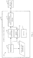
- FIG. 1 shows one embodiment of a block diagram of a moisture sensing system 100 on an agricultural machine 102.
- Agricultural machine 102 can be a wide variety of different types of machines, such as a combine, a baler, a cotton harvester or a wide variety of other agricultural machines.
- Agricultural machine 102 illustratively comes into contact with sensed material 104 and has a conveying mechanism that conveys the material 104 through machine 102.
- the sensed material 104 can be material that is being harvested by agricultural machine 102.
- the sensed material 104 can be grain.
- the sensed material 104 can be hay, cotton, or other baled material. These are examples only.
- Moisture sensing system 100 illustratively includes processor 106, drive component 108, co-planar moisture sensor probe 110, sense component 112, and it can include other components 114 as well.
- Processor 106 is illustratively a computer processor with associated memory and timing circuitry, not separately shown. It controls drive component 108 to drive an electrode in co-planar moisture sensor probe 110.
- Sense component 112 illustratively senses a parameter (such as current) in one of the electrodes in co-planar moisture sensor probe 110 and provides that signal to processor 106.
- Processor 106 calculates a moisture value indicative of the moisture of sensed material 104. The calculated moisture is indicated by block 116 in Figure 1 .
- Calculated moisture 116 can be used in a wide variety of different ways. For instance, it can be combined with a position signal in order to generate a moisture map. It can also be used in yield monitoring applications and to provide information to assist in making decisions about harvesting, storage, and future processing. It can be used in a wide variety of other ways as well.
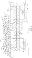
- FIG 2 is a partial schematic, partial cross-sectional view of one embodiment of co-planar moisture sensor probe 110, drive component 108 and sense component 112.
- probe 110 includes a drive electrode 120 and a sense electrode 122. It will be appreciated that a plurality of different electrodes can be used and two are shown in the embodiment in Figure 2 for the sake of example only.
- Drive electrode 120 has a material facing surface 124 that is substantially co-planar with a material facing surface 126 of sense electrode 122. They are illustratively co-planar so that the material being measured 128 can come into contact with electrodes 120 and 122 on their co-planar surfaces, or at least come into close proximity to the surfaces. Each of the electrodes 120 and 122 illustratively has an insulator 128 and 130, respectively, disposed thereabout. Thus, electrodes 120 and 122 have insulators 128 and 130, respectively, encompassing all of their surfaces, except for the material facing surfaces 124 and 126.
- Probe 110 also illustratively includes a ground electrode 132.
- Ground electrode 132 surrounds at least sense electrode 122 (and its insulator 130). It can surround both electrodes 120 and 122 and both insulators 128 and 130. However, it leaves exposed the material facing surfaces 124 and 126 of electrodes 120 and 122.
- probe 110 is coupled to structural machine housing 134.
- This can be a housing of a combine, a baler, or another agricultural machine 102.
- probe 110 can be mounted to housing 134 on the grain bypass of a clean grain elevator on the combine.
- it can be mounted on the bottom boot area of the clean grain elevator.
- the sensor is sensing moisture of other biomass material (such as material other than grain)
- it can be mounted to the rear of the rotor on a combine or on the residue hood adjacent the discharge beater of a combine.
- agricultural machine 102 is a baler or cotton harvester, it can be mounted on an interior side wall of the bale chamber or harvester, or in other locations.
- Drive component 108 illustratively includes a controllable oscillator 136.
- Oscilator 136 can be controlled by processor 106 to provide an alternating current (AC) drive signal to an operational amplifier 138 which, itself, provides an alternating current (AC) drive voltage V D at its output. Voltage V D is applied to drive electrode 120 as an excitation signal.
- Sense component 112 illustratively includes a zero input impedance current sense amplifier 140 connected to an RC circuit formed by resistor 142 and capacitor 144. Sense component 112 is coupled to sense electrode 122 to receive sense current I S at its input. It provides, at its output, a signal 146 indicative of sense current I S .
- electrode 120 When the drive voltage V D is applied to drive electrode 120, electrode 120 illustratively produces a fringing electric field represented by electric field flux lines 146.
- the drive voltage V D can be provided at one or more frequencies in order to set up the electric field represented by flux lines 146.
- the electric field is set up by electrode 120, through the sensed material 104.
- the electric field links with all surrounding grounded surfaces in the plane of the material facing surfaces 124 and 126 of electrodes 120 and 122.
- Sense electrode 126 is illustratively held at ground potential.
- the current induced in sense electrode 122 by the electric field passing through sense electrode 122 is referred to above as the sense current I S .
- Guard electrode 132 is also held at ground potential and inhibits any portion of the electric field that passes through the insulators 128 and 130, or paths other than through material 104, from reaching sense electrode 122. Instead, the parasitic current I P that is produced by flux lines through the insulator material or through other paths, other than the sensed material 104, is shorted to ground through guard electrode 132. It does not reach sense electrode 122. Thus, guard electrode 132 inhibits or blocks flux paths that do not pass solely through sensed material 104. They therefore do not contribute to the sensed current I S .
- the sensed current I S which is sensed in the sense electrode 122 (instead of the drive electrode 120) is induced only by the flux paths passing through the material being measured 104 and reaching sense electrode 122.
- the sense current I S is thus not influenced by parasitic flux paths through the insulators or directly to ground. All of that flux links with the grounded guard 132, so it does not affect sense current I S .
- Probe 110 is thus configured to measure only the permittivity of the sensed material 104 and is insensitive to characteristics of the probe structure (including, but not limited to, characteristics of the insulators 128 and 130 surrounding electrodes 120 and 122).
- characteristics of the probe structure including, but not limited to, characteristics of the insulators 128 and 130 surrounding electrodes 120 and 122).
- parasitic capacitive and conductive coupling between the drive electrode 120 and ground is substantially eliminated from the sensed current I S .
- guard electrode 132 and the sense electrode 122 By maintaining both guard electrode 132 and the sense electrode 122 at ground potential, sensitivity to parasitic capacitance and conductance between the sense electrode 122 and the surrounding grounded structure is substantially eliminated as well.
- sensor probe 110 can be provided. For instance, if the drive electrode 120 and sense electrode 122 are moved further apart (such as in the direction indicated by arrow 150) or if they are moved closer together, this can affect the signal level of the sense current I S . This is because the spacing between the two electrodes 120 and 122 will affect the depth of penetration of flux lines 146 into the sensed material 104. Moving them further apart will allow the flux lines 146 to penetrate more deeply into the sensed material 104 in the direction indicated by arrow 152. Moving them closer together will result in the flux lines 146 penetrating less deeply.
- Figure 2A shows another exemplary configuration of co-planar moisture sensor probe 110.
- the embodiment shown in Figure 2A is similar to that shown in Figure 2 , in some ways, and similar items are similarly numbered. It can be see, however, that in the embodiment shown in Figure 2A , probe 110 not only includes drive electrode 120 and sense electrode 122, but it also includes a second sense electrode 156.
- Sense electrode 156 also has an insulator 158 disposed thereabout. Like insulators 128 and 130, it is disposed about all surfaces of electrode 156 except the material facing surface 160 which is, itself, co-planar with the material facing surfaces 124 and 126 of electrodes 120 and 122. In addition, it can be seen that grounded guard electrode 132 also extends about all of the surfaces of sense electrode 156 (and insulator 158), except surface 160.
- the embodiment of Figure 2A includes the additional sense electrode 156.
- Guard electrode 132 prevents flux lines 146 (other than those through the sensed material) from reaching sense electrode 156. Therefore, current induced by the flux lines 146 that reach sense electrodes 122 and 156 will be represented in sense current I S .
- multiple drive electrodes can be used with a single sense electrode, or there can be multiple drive electrodes and multiple sense electrodes. All of these various configurations are contemplated herein.
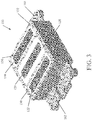
- Figure 3 is a perspective, pictorial view of one embodiment of the sensor probe 110 shown in Figure 2A . Similar items to those shown in Figure 2A are similarly numbered in Figure 3 .
- probe 110 has a set of mounting structures 162 and 164 that can be used to mount probe 110 to machine housing 134.
- the surfaces 124, 126 and 160 of electrodes 120, 122 and 156, respectively are mounted flush with the machine housing 134. In another embodiment, however, they can protrude from the machine housing 134 in the direction of the material being measured 104 or they can be set back in the opposite direction. All of these embodiments are contemplated herein.
- grounded guard electrode 132 has through holes.
- the through holes receive electrical connection elements that connect a circuit board that includes drive component 108 and sense component 112 to the corresponding electrodes 120, 122 and 156.
- the particular configuration of the connections in sensor probe 110 can vary with the application. For instance, where probe 110 is mounted within a grain elevator, a clean grain tank, in the bale chamber of a baler, or on the spout of a combine or other harvester, the connections used to connect probe 110 to the machine housing 134 may vary. Also, the configuration may change, based upon the particular nature of the harvested material. When the harvested material is hay, cotton, or another relatively soft material, it may take one configuration (such as being flush with the machine housing 134). When it is a grain or other granular material, it may take another configuration, such as protruding slightly from the machine housing 134. Of course, these are given by way of example only, and the mounting configuration can vary in other ways as well.
- Figure 4 shows another pictorial, perspective view of another embodiment of sensor probe 110.
- probe 110 shown in Figure 4 includes four electrodes, 170, 172, 174 and 176.
- Each of the electrodes has a material facing surface that is seen in Figure 4 . All of the material facing surfaces are co-planar.
- Each of the electrodes is also surrounded by an insulating material 178, 180, 182 and 184, respectively.
- the grounded guard 132 is disposed about all of the surfaces of the electrodes except their material facing surfaces (and about the insulators as well).
- some of the electrodes can be drive electrodes, while others can be sense electrodes.
- electrode 172 can be a drive electrode, while electrodes 170, 174 and 176 are sense electrodes.
- electrode 176 is a fill sense electrode. It can be used when sensing grain. The probe is oriented so that it lies in a vertical plane and electrode 176 is higher than the other electrodes. In this orientation, when current above a minimum amount is sensed in electrode 176 the other electrodes are known to be completely covered with material (such as grain) and a valid permittivity measurement can be made.
- the drive electrodes and sense electrodes can be different as well.
- Figure 4 shows that the particular geometrical configuration of the electrodes can take a wide variety of different forms.
- the complex drive voltage and resulting complex current can be measured and used to compute the permittivity of the sensed material 104. This, in turn, can be used to generate a measure of the moisture of material 104.
- the grounded guard electrode 132 that forms part of the probe structure is positioned relative to the sense electrodes so as to shield the sense electrodes from substantially all electric field flux that does not pass substantially only through the space where the sensed material 104 resides. Flux that is generated by the drive electrode and that passes through the insulator material or other things links with the grounded guard and is not sensed.
- the probe measures only the permittivity of the sensed material 104 and is relatively insensitive to characteristics of the probe structure (such as the insulators surrounding the electrodes). Further, by sensing currents in the sense electrode rather than in the drive electrode, parasitic capacitive and conductive coupling between the drive electrode and ground is substantially eliminated from the sensed current. Because the sense electrode is maintained at ground potential, sensitivity to parasitic capacitance and conductance between the sense electrode and the surrounding grounded structure is substantially eliminated as well.
Landscapes
- General Physics & Mathematics (AREA)
- Physics & Mathematics (AREA)
- Life Sciences & Earth Sciences (AREA)
- Chemical & Material Sciences (AREA)
- Environmental Sciences (AREA)
- Biochemistry (AREA)
- Electrochemistry (AREA)
- Engineering & Computer Science (AREA)
- Health & Medical Sciences (AREA)
- Analytical Chemistry (AREA)
- General Health & Medical Sciences (AREA)
- Chemical Kinetics & Catalysis (AREA)
- Immunology (AREA)
- Pathology (AREA)
- Power Engineering (AREA)
- Mechanical Engineering (AREA)
- Investigating Or Analyzing Materials By The Use Of Electric Means (AREA)
Claims (9)
- Capteur d'humidité, comprenant :un composant d'attaque (108) qui génère un signal d'attaque ;une électrode d'attaque (120) couplée au composant d'attaque (108) et présentant une surface (124) en regard d'une matière détectée, l'électrode d'attaque (120), lorsqu'elle est attaquée par le signal d'attaque, générant un champ électrique ;une électrode de détection (122) présentant une surface (126) en regard de la matière détectée, l'électrode d'attaque (120) et l'électrode de détection (120) étant couplées structuralement entre elles de sorte que les surfaces en regard de la matière détectée de l'électrode d'attaque (120) et de l'électrode de détection (122) sont généralement coplanaires ;un composant de détection (112) couplé à l'électrode de détection (122) et générant un signal de détection indiquant qu'un courant produit par l'électrode de détection (122) par le champ électrique, généré par l'électrode d'attaque (120), parvient à l'électrode de détection (122) ;une électrode de garde (132) placée autour de l'électrode de détection (122) pour former une protection autour de l'électrode de détection (122) et pour définir une ouverture destinée à rendre apparente la surface (126) en regard de la matière détectée,un isolateur (130) placé entre l'électrode de détection (122) et l'électrode de garde (132) et un isolateur (128) placé entre l'électrode d'attaque (120) et l'électrode de garde (132),caractérisé en ce que l'électrode de garde (132) est placée autour de sensiblement toutes les surfaces de l'électrode de détection (122) autres que la surface (126) en regard de la matière détectée, l'électrode de garde (132) étant agencée de manière à empêcher le champ électrique d'atteindre l'électrode de détection (122) autrement que par la surface (126) en regard de la matière détectée.
- Capteur d'humidité selon la revendication 1, dans lequel l'électrode de garde (132) et l'électrode de détection (122) sont reliées à un potentiel de tension de référence.
- Capteur d'humidité selon la revendication 2, dans lequel le composant de détection (112) comprend un amplificateur de détection de courant (140) présentant une entrée maintenue au potentiel de tension de référence et recevant, à l'entrée, le courant produit dans l'électrode de détection (122).
- Capteur d'humidité selon la revendication 3, dans lequel le composant d'attaque (108) comprend un composant en courant alternatif (CA) (136) générant le signal d'attaque sous forme d'un signal d'excitation en CA.
- Capteur d'humidité selon la revendication 4 et comprenant en outre un processeur (106) d'ordinateur qui mesure le signal d'excitation en CA et le signal de détection et détermine un niveau d'humidité de matière à proximité des surfaces (124, 126) en regard de la matière détectée de l'électrode d'attaque (120) et de l'électrode de détection (122) sur la base du signal d'excitation en CA et du signal de détection.
- Machine agricole (102) transportant de la matière agricole, comprenant un mécanisme d'acheminement de matière définissant une zone de matière par laquelle passe la matière agricole ; et un capteur d'humidité selon l'une des revendications 1 à 5.
- Machine agricole (102) selon la revendication 6, dans laquelle le mécanisme d'acheminement de matière comprend une chambre de pressage d'une presse à balles.
- Machine agricole (102) selon la revendication 7, dans laquelle le capteur d'humidité est monté sur une paroi latérale de la chambre de pressage de sorte que les surfaces en regard de la matière de l'électrode d'attaque (120) et de l'électrode de détection (122) sont en regard d'un intérieur de la chambre de pressage.
- Machine agricole (102) selon la revendication 6, dans laquelle le mécanisme d'acheminement de matière comprend un mécanisme d'acheminement de grains d'une moissonneuse-batteuse et/ou une partie d'évacuation de résidus d'une moissonneuse-batteuse.
Applications Claiming Priority (1)
| Application Number | Priority Date | Filing Date | Title |
|---|---|---|---|
| US14/245,069 US9494538B2 (en) | 2014-04-04 | 2014-04-04 | Agricultural moisture sensor with co-planar electrodes |
Publications (2)
| Publication Number | Publication Date |
|---|---|
| EP2927675A1 EP2927675A1 (fr) | 2015-10-07 |
| EP2927675B1 true EP2927675B1 (fr) | 2020-06-17 |
Family
ID=52780834
Family Applications (1)
| Application Number | Title | Priority Date | Filing Date |
|---|---|---|---|
| EP15160069.9A Active EP2927675B1 (fr) | 2014-04-04 | 2015-03-20 | Capteur agricole d'humidité avec electrodes coplanaires |
Country Status (5)
| Country | Link |
|---|---|
| US (1) | US9494538B2 (fr) |
| EP (1) | EP2927675B1 (fr) |
| CN (1) | CN104977328B (fr) |
| AU (1) | AU2015201572B2 (fr) |
| BR (1) | BR102015006945B1 (fr) |
Families Citing this family (21)
| Publication number | Priority date | Publication date | Assignee | Title |
|---|---|---|---|---|
| US9949450B2 (en) * | 2014-11-03 | 2018-04-24 | MorpH2O Water Management, LLC | Soil moisture probe and system with temperature adjustment |
| US9967696B2 (en) | 2015-06-12 | 2018-05-08 | IdeaCuria Inc. | System and method for smart material monitoring |
| US11382275B2 (en) | 2016-08-31 | 2022-07-12 | Tube-Line Manufacturing Limited | Continuous round baler accumulation chamber |
| US10863672B2 (en) | 2017-11-06 | 2020-12-15 | Deere & Company | Radio frequency measurement device for measuring harvested agricultural material |
| US10871458B2 (en) | 2017-11-06 | 2020-12-22 | Deere & Company | Radio frequency measurement device for measuring grain loss |
| US11268922B2 (en) * | 2018-01-19 | 2022-03-08 | Transtech Systems, Inc. | Electromagnetic impedance spectroscopy apparatus and related planar sensor system |
| CA3082932A1 (fr) | 2018-01-23 | 2019-08-01 | Dennis M. Anderson | Analyse de materiau poreux a l'aide d'un appareil de test etalonne en laboratoire et de donnees d'echantillon |
| KR102143684B1 (ko) * | 2018-04-12 | 2020-08-13 | (주) 텔로팜 | 토양 내 수분 함량 측정 장치 |
| WO2019209802A1 (fr) | 2018-04-24 | 2019-10-31 | Transtech Systems, Inc. | Système de condensateur à plaques parallèles permettant la détermination de caractéristiques d'impédance d'un matériau testé (mut) |
| CN209326840U (zh) | 2018-12-27 | 2019-08-30 | 热敏碟公司 | 压力传感器及压力变送器 |
| US11016049B2 (en) * | 2019-04-17 | 2021-05-25 | Deere & Company | Agricultural moisture and test weight sensor with co-planar electrodes |
| US12372496B2 (en) | 2020-04-24 | 2025-07-29 | Agco Corporation | Methods of measuring harvested crop material |
| CA3175292A1 (fr) * | 2020-04-24 | 2021-10-28 | Agco Corporation | Machines agricoles comprenant des capteurs capacitifs, et procedes et appareil associes |
| US11680912B2 (en) | 2020-05-14 | 2023-06-20 | Transtech Systems, Inc. | Sensor system to apply electromagnetic fields for electromagnetic impedance spectroscopy in-process monitoring of fluids |
| DE102020113658A1 (de) * | 2020-05-20 | 2021-11-25 | Claas Selbstfahrende Erntemaschinen Gmbh | Sensorsystem zur Erfassung von Elementen eines Erntegutstromes |
| DE102020113667A1 (de) * | 2020-05-20 | 2021-11-25 | Claas Selbstfahrende Erntemaschinen Gmbh | Mähdrescher mit einem Sensorsystem |
| EP4232809A4 (fr) * | 2020-11-24 | 2024-10-16 | Raja Tuli | Estimation de l'humidité ou de la saturation d'un article absorbant |
| US20220249296A1 (en) * | 2021-02-11 | 2022-08-11 | Raja Singh Tuli | Moisture detection and estimation with multiple frequencies |
| WO2022182666A1 (fr) * | 2021-02-23 | 2022-09-01 | Purdue Research Foundation | Humidimètre de grain interconnecté à des téléphones intelligents |
| CN115931978A (zh) * | 2022-08-23 | 2023-04-07 | 石河子大学 | 车载式籽棉回潮率及含杂率一体化检测装置 |
| DE102023108762A1 (de) * | 2023-04-05 | 2024-10-10 | Claas Selbstfahrende Erntemaschinen Gmbh | Sensoranordnung |
Family Cites Families (14)
| Publication number | Priority date | Publication date | Assignee | Title |
|---|---|---|---|---|
| US3491292A (en) | 1967-04-28 | 1970-01-20 | Industrial Nucleonics Corp | Standard sample and method for simulating the effect of moist paper and the like on a capacitive gauge for dielectric materials |
| DE2239359A1 (de) | 1972-08-10 | 1974-02-21 | Bosch Gmbh Robert | Schaltanordnung mit einem kapazitiven detektor |
| DE19610599C2 (de) | 1996-02-06 | 2001-08-09 | Liebherr Mischtechnik Gmbh | Feuchtesensor |
| US6388453B1 (en) | 1999-01-25 | 2002-05-14 | Bryan D. Greer | Swept-frequency dielectric moisture and density sensor |
| US6686749B2 (en) | 2001-10-25 | 2004-02-03 | Deere & Company | Multiple frequency grain moisture sensor for combines |
| US7129713B2 (en) | 2004-01-21 | 2006-10-31 | Delmhorst Instrument Co. | Capacitive moisture sensor |
| US8079248B2 (en) * | 2005-11-17 | 2011-12-20 | Nxp B.V. | Moisture sensor |
| US8456427B2 (en) * | 2007-03-29 | 2013-06-04 | Cirque Corporation | Floating capacitive couplers used to enhance signal coupling in a capacitive touchpad |
| TWI444876B (zh) * | 2007-04-05 | 2014-07-11 | Qrg Ltd | 二維位置感應器 |
| US8707781B2 (en) * | 2008-09-11 | 2014-04-29 | Nxp, B.V. | Sensor has combined in-plane and parallel-plane configuration |
| US20110048813A1 (en) * | 2009-09-03 | 2011-03-03 | Esat Yilmaz | Two-dimensional position sensor |
| JP5470512B2 (ja) * | 2009-11-30 | 2014-04-16 | アルプス電気株式会社 | 湿度検出センサ |
| US20130088245A1 (en) * | 2011-10-10 | 2013-04-11 | Kla-Tencor Corporation | Capacitive Inspection Of EUV Photomasks |
| US20140026652A1 (en) * | 2012-07-25 | 2014-01-30 | Timothy Cummins | Sensor for measuring high humidity conditions and/or condensation |
-
2014
- 2014-04-04 US US14/245,069 patent/US9494538B2/en active Active
-
2015
- 2015-03-20 EP EP15160069.9A patent/EP2927675B1/fr active Active
- 2015-03-27 AU AU2015201572A patent/AU2015201572B2/en active Active
- 2015-03-27 BR BR102015006945-6A patent/BR102015006945B1/pt active IP Right Grant
- 2015-04-02 CN CN201510154556.0A patent/CN104977328B/zh active Active
Non-Patent Citations (1)
| Title |
|---|
| None * |
Also Published As
| Publication number | Publication date |
|---|---|
| AU2015201572B2 (en) | 2019-05-09 |
| EP2927675A1 (fr) | 2015-10-07 |
| BR102015006945B1 (pt) | 2022-06-14 |
| CN104977328B (zh) | 2019-03-29 |
| US9494538B2 (en) | 2016-11-15 |
| BR102015006945A2 (pt) | 2015-12-29 |
| AU2015201572A1 (en) | 2015-10-22 |
| US20150285752A1 (en) | 2015-10-08 |
| CN104977328A (zh) | 2015-10-14 |
Similar Documents
| Publication | Publication Date | Title |
|---|---|---|
| EP2927675B1 (fr) | Capteur agricole d'humidité avec electrodes coplanaires | |
| US11016049B2 (en) | Agricultural moisture and test weight sensor with co-planar electrodes | |
| US6982562B2 (en) | Multiple frequency grain moisture sensor for combines | |
| US7256588B2 (en) | Capacitive sensor and method for non-contacting gap and dielectric medium measurement | |
| US5671633A (en) | Plate array for moisture sensor with reduced sensitivity to loading effects | |
| US6242927B1 (en) | Method and apparatus measuring parameters of material | |
| KR930701753A (ko) | 물질의 유전 특성 및 구조적 특성의 측정 장치 및 방법 | |
| US12575494B2 (en) | Capacitive parameter measurement in a self-propelled forage harvester | |
| US20110101997A1 (en) | Flush-Mounted Capacitive Sensor Mount | |
| US12228537B2 (en) | Agricultural machines comprising capacitive sensors, and related methods and apparatus | |
| EP0556682B1 (fr) | Capteur capacitif électronique en forme de barre | |
| JPH0933317A (ja) | 静電容量センサ | |
| Mohamed et al. | Evaluation of Differential Capacitance Technique in LC Resonant-Based Capacitance Sensor for Moisture Content Detection in Paddy Seeds | |
| US7525222B2 (en) | Sensor assembly and sensing system for sensing human tissue in a protected area of a machine | |
| CN107515015A (zh) | 电容传感器及割草机 | |
| SU1165967A1 (ru) | Способ измерени влажности | |
| JP2005151839A (ja) | 穀粒貯留装置 | |
| CA1143792A (fr) | Detecteur d'humidite | |
| US8781771B1 (en) | Measurement of material properties | |
| Yang et al. | Measurement of grain moisture with a coplanar electrode capacitance probe | |
| CN204405587U (zh) | 一种多极板土壤湿度测量装置 | |
| JP2021110665A (ja) | 水分量測定装置 | |
| JP2007163312A (ja) | 穀粒貯留量検出装置 |
Legal Events
| Date | Code | Title | Description |
|---|---|---|---|
| PUAI | Public reference made under article 153(3) epc to a published international application that has entered the european phase |
Free format text: ORIGINAL CODE: 0009012 |
|
| AK | Designated contracting states |
Kind code of ref document: A1 Designated state(s): AL AT BE BG CH CY CZ DE DK EE ES FI FR GB GR HR HU IE IS IT LI LT LU LV MC MK MT NL NO PL PT RO RS SE SI SK SM TR |
|
| AX | Request for extension of the european patent |
Extension state: BA ME |
|
| 17P | Request for examination filed |
Effective date: 20160407 |
|
| RBV | Designated contracting states (corrected) |
Designated state(s): AL AT BE BG CH CY CZ DE DK EE ES FI FR GB GR HR HU IE IS IT LI LT LU LV MC MK MT NL NO PL PT RO RS SE SI SK SM TR |
|
| STAA | Information on the status of an ep patent application or granted ep patent |
Free format text: STATUS: EXAMINATION IS IN PROGRESS |
|
| 17Q | First examination report despatched |
Effective date: 20171221 |
|
| GRAP | Despatch of communication of intention to grant a patent |
Free format text: ORIGINAL CODE: EPIDOSNIGR1 |
|
| STAA | Information on the status of an ep patent application or granted ep patent |
Free format text: STATUS: GRANT OF PATENT IS INTENDED |
|
| INTG | Intention to grant announced |
Effective date: 20200110 |
|
| GRAS | Grant fee paid |
Free format text: ORIGINAL CODE: EPIDOSNIGR3 |
|
| GRAA | (expected) grant |
Free format text: ORIGINAL CODE: 0009210 |
|
| STAA | Information on the status of an ep patent application or granted ep patent |
Free format text: STATUS: THE PATENT HAS BEEN GRANTED |
|
| AK | Designated contracting states |
Kind code of ref document: B1 Designated state(s): AL AT BE BG CH CY CZ DE DK EE ES FI FR GB GR HR HU IE IS IT LI LT LU LV MC MK MT NL NO PL PT RO RS SE SI SK SM TR |
|
| REG | Reference to a national code |
Ref country code: GB Ref legal event code: FG4D |
|
| REG | Reference to a national code |
Ref country code: CH Ref legal event code: EP |
|
| REG | Reference to a national code |
Ref country code: DE Ref legal event code: R096 Ref document number: 602015054250 Country of ref document: DE |
|
| REG | Reference to a national code |
Ref country code: IE Ref legal event code: FG4D |
|
| REG | Reference to a national code |
Ref country code: AT Ref legal event code: REF Ref document number: 1281934 Country of ref document: AT Kind code of ref document: T Effective date: 20200715 |
|
| PG25 | Lapsed in a contracting state [announced via postgrant information from national office to epo] |
Ref country code: SE Free format text: LAPSE BECAUSE OF FAILURE TO SUBMIT A TRANSLATION OF THE DESCRIPTION OR TO PAY THE FEE WITHIN THE PRESCRIBED TIME-LIMIT Effective date: 20200617 Ref country code: NO Free format text: LAPSE BECAUSE OF FAILURE TO SUBMIT A TRANSLATION OF THE DESCRIPTION OR TO PAY THE FEE WITHIN THE PRESCRIBED TIME-LIMIT Effective date: 20200917 Ref country code: FI Free format text: LAPSE BECAUSE OF FAILURE TO SUBMIT A TRANSLATION OF THE DESCRIPTION OR TO PAY THE FEE WITHIN THE PRESCRIBED TIME-LIMIT Effective date: 20200617 Ref country code: LT Free format text: LAPSE BECAUSE OF FAILURE TO SUBMIT A TRANSLATION OF THE DESCRIPTION OR TO PAY THE FEE WITHIN THE PRESCRIBED TIME-LIMIT Effective date: 20200617 Ref country code: GR Free format text: LAPSE BECAUSE OF FAILURE TO SUBMIT A TRANSLATION OF THE DESCRIPTION OR TO PAY THE FEE WITHIN THE PRESCRIBED TIME-LIMIT Effective date: 20200918 |
|
| REG | Reference to a national code |
Ref country code: LT Ref legal event code: MG4D |
|
| REG | Reference to a national code |
Ref country code: NL Ref legal event code: MP Effective date: 20200617 |
|
| PG25 | Lapsed in a contracting state [announced via postgrant information from national office to epo] |
Ref country code: RS Free format text: LAPSE BECAUSE OF FAILURE TO SUBMIT A TRANSLATION OF THE DESCRIPTION OR TO PAY THE FEE WITHIN THE PRESCRIBED TIME-LIMIT Effective date: 20200617 Ref country code: BG Free format text: LAPSE BECAUSE OF FAILURE TO SUBMIT A TRANSLATION OF THE DESCRIPTION OR TO PAY THE FEE WITHIN THE PRESCRIBED TIME-LIMIT Effective date: 20200917 Ref country code: LV Free format text: LAPSE BECAUSE OF FAILURE TO SUBMIT A TRANSLATION OF THE DESCRIPTION OR TO PAY THE FEE WITHIN THE PRESCRIBED TIME-LIMIT Effective date: 20200617 Ref country code: HR Free format text: LAPSE BECAUSE OF FAILURE TO SUBMIT A TRANSLATION OF THE DESCRIPTION OR TO PAY THE FEE WITHIN THE PRESCRIBED TIME-LIMIT Effective date: 20200617 |
|
| REG | Reference to a national code |
Ref country code: AT Ref legal event code: MK05 Ref document number: 1281934 Country of ref document: AT Kind code of ref document: T Effective date: 20200617 |
|
| PG25 | Lapsed in a contracting state [announced via postgrant information from national office to epo] |
Ref country code: NL Free format text: LAPSE BECAUSE OF FAILURE TO SUBMIT A TRANSLATION OF THE DESCRIPTION OR TO PAY THE FEE WITHIN THE PRESCRIBED TIME-LIMIT Effective date: 20200617 Ref country code: AL Free format text: LAPSE BECAUSE OF FAILURE TO SUBMIT A TRANSLATION OF THE DESCRIPTION OR TO PAY THE FEE WITHIN THE PRESCRIBED TIME-LIMIT Effective date: 20200617 |
|
| PG25 | Lapsed in a contracting state [announced via postgrant information from national office to epo] |
Ref country code: RO Free format text: LAPSE BECAUSE OF FAILURE TO SUBMIT A TRANSLATION OF THE DESCRIPTION OR TO PAY THE FEE WITHIN THE PRESCRIBED TIME-LIMIT Effective date: 20200617 Ref country code: IT Free format text: LAPSE BECAUSE OF FAILURE TO SUBMIT A TRANSLATION OF THE DESCRIPTION OR TO PAY THE FEE WITHIN THE PRESCRIBED TIME-LIMIT Effective date: 20200617 Ref country code: CZ Free format text: LAPSE BECAUSE OF FAILURE TO SUBMIT A TRANSLATION OF THE DESCRIPTION OR TO PAY THE FEE WITHIN THE PRESCRIBED TIME-LIMIT Effective date: 20200617 Ref country code: EE Free format text: LAPSE BECAUSE OF FAILURE TO SUBMIT A TRANSLATION OF THE DESCRIPTION OR TO PAY THE FEE WITHIN THE PRESCRIBED TIME-LIMIT Effective date: 20200617 Ref country code: SM Free format text: LAPSE BECAUSE OF FAILURE TO SUBMIT A TRANSLATION OF THE DESCRIPTION OR TO PAY THE FEE WITHIN THE PRESCRIBED TIME-LIMIT Effective date: 20200617 Ref country code: AT Free format text: LAPSE BECAUSE OF FAILURE TO SUBMIT A TRANSLATION OF THE DESCRIPTION OR TO PAY THE FEE WITHIN THE PRESCRIBED TIME-LIMIT Effective date: 20200617 Ref country code: ES Free format text: LAPSE BECAUSE OF FAILURE TO SUBMIT A TRANSLATION OF THE DESCRIPTION OR TO PAY THE FEE WITHIN THE PRESCRIBED TIME-LIMIT Effective date: 20200617 Ref country code: PT Free format text: LAPSE BECAUSE OF FAILURE TO SUBMIT A TRANSLATION OF THE DESCRIPTION OR TO PAY THE FEE WITHIN THE PRESCRIBED TIME-LIMIT Effective date: 20201019 |
|
| PG25 | Lapsed in a contracting state [announced via postgrant information from national office to epo] |
Ref country code: PL Free format text: LAPSE BECAUSE OF FAILURE TO SUBMIT A TRANSLATION OF THE DESCRIPTION OR TO PAY THE FEE WITHIN THE PRESCRIBED TIME-LIMIT Effective date: 20200617 Ref country code: SK Free format text: LAPSE BECAUSE OF FAILURE TO SUBMIT A TRANSLATION OF THE DESCRIPTION OR TO PAY THE FEE WITHIN THE PRESCRIBED TIME-LIMIT Effective date: 20200617 Ref country code: IS Free format text: LAPSE BECAUSE OF FAILURE TO SUBMIT A TRANSLATION OF THE DESCRIPTION OR TO PAY THE FEE WITHIN THE PRESCRIBED TIME-LIMIT Effective date: 20201017 |
|
| REG | Reference to a national code |
Ref country code: DE Ref legal event code: R097 Ref document number: 602015054250 Country of ref document: DE |
|
| PLBE | No opposition filed within time limit |
Free format text: ORIGINAL CODE: 0009261 |
|
| STAA | Information on the status of an ep patent application or granted ep patent |
Free format text: STATUS: NO OPPOSITION FILED WITHIN TIME LIMIT |
|
| PG25 | Lapsed in a contracting state [announced via postgrant information from national office to epo] |
Ref country code: DK Free format text: LAPSE BECAUSE OF FAILURE TO SUBMIT A TRANSLATION OF THE DESCRIPTION OR TO PAY THE FEE WITHIN THE PRESCRIBED TIME-LIMIT Effective date: 20200617 |
|
| 26N | No opposition filed |
Effective date: 20210318 |
|
| PG25 | Lapsed in a contracting state [announced via postgrant information from national office to epo] |
Ref country code: SI Free format text: LAPSE BECAUSE OF FAILURE TO SUBMIT A TRANSLATION OF THE DESCRIPTION OR TO PAY THE FEE WITHIN THE PRESCRIBED TIME-LIMIT Effective date: 20200617 |
|
| PG25 | Lapsed in a contracting state [announced via postgrant information from national office to epo] |
Ref country code: MC Free format text: LAPSE BECAUSE OF FAILURE TO SUBMIT A TRANSLATION OF THE DESCRIPTION OR TO PAY THE FEE WITHIN THE PRESCRIBED TIME-LIMIT Effective date: 20200617 |
|
| REG | Reference to a national code |
Ref country code: CH Ref legal event code: PL |
|
| GBPC | Gb: european patent ceased through non-payment of renewal fee |
Effective date: 20210320 |
|
| REG | Reference to a national code |
Ref country code: BE Ref legal event code: MM Effective date: 20210331 |
|
| PG25 | Lapsed in a contracting state [announced via postgrant information from national office to epo] |
Ref country code: LU Free format text: LAPSE BECAUSE OF NON-PAYMENT OF DUE FEES Effective date: 20210320 Ref country code: LI Free format text: LAPSE BECAUSE OF NON-PAYMENT OF DUE FEES Effective date: 20210331 Ref country code: CH Free format text: LAPSE BECAUSE OF NON-PAYMENT OF DUE FEES Effective date: 20210331 Ref country code: GB Free format text: LAPSE BECAUSE OF NON-PAYMENT OF DUE FEES Effective date: 20210320 Ref country code: IE Free format text: LAPSE BECAUSE OF NON-PAYMENT OF DUE FEES Effective date: 20210320 Ref country code: FR Free format text: LAPSE BECAUSE OF NON-PAYMENT OF DUE FEES Effective date: 20210331 |
|
| PG25 | Lapsed in a contracting state [announced via postgrant information from national office to epo] |
Ref country code: BE Free format text: LAPSE BECAUSE OF NON-PAYMENT OF DUE FEES Effective date: 20210331 |
|
| PG25 | Lapsed in a contracting state [announced via postgrant information from national office to epo] |
Ref country code: HU Free format text: LAPSE BECAUSE OF FAILURE TO SUBMIT A TRANSLATION OF THE DESCRIPTION OR TO PAY THE FEE WITHIN THE PRESCRIBED TIME-LIMIT; INVALID AB INITIO Effective date: 20150320 |
|
| PG25 | Lapsed in a contracting state [announced via postgrant information from national office to epo] |
Ref country code: CY Free format text: LAPSE BECAUSE OF FAILURE TO SUBMIT A TRANSLATION OF THE DESCRIPTION OR TO PAY THE FEE WITHIN THE PRESCRIBED TIME-LIMIT Effective date: 20200617 |
|
| PG25 | Lapsed in a contracting state [announced via postgrant information from national office to epo] |
Ref country code: MK Free format text: LAPSE BECAUSE OF FAILURE TO SUBMIT A TRANSLATION OF THE DESCRIPTION OR TO PAY THE FEE WITHIN THE PRESCRIBED TIME-LIMIT Effective date: 20200617 |
|
| PG25 | Lapsed in a contracting state [announced via postgrant information from national office to epo] |
Ref country code: MT Free format text: LAPSE BECAUSE OF FAILURE TO SUBMIT A TRANSLATION OF THE DESCRIPTION OR TO PAY THE FEE WITHIN THE PRESCRIBED TIME-LIMIT Effective date: 20200617 |
|
| PG25 | Lapsed in a contracting state [announced via postgrant information from national office to epo] |
Ref country code: TR Free format text: LAPSE BECAUSE OF FAILURE TO SUBMIT A TRANSLATION OF THE DESCRIPTION OR TO PAY THE FEE WITHIN THE PRESCRIBED TIME-LIMIT Effective date: 20200617 |
|
| PGFP | Annual fee paid to national office [announced via postgrant information from national office to epo] |
Ref country code: DE Payment date: 20260219 Year of fee payment: 12 |