EP2927679B1 - Gerät für die Messung und Analyse des Multiple-Breath-Stickstoff-Auswaschverfahrens - Google Patents
Gerät für die Messung und Analyse des Multiple-Breath-Stickstoff-Auswaschverfahrens Download PDFInfo
- Publication number
- EP2927679B1 EP2927679B1 EP14198579.6A EP14198579A EP2927679B1 EP 2927679 B1 EP2927679 B1 EP 2927679B1 EP 14198579 A EP14198579 A EP 14198579A EP 2927679 B1 EP2927679 B1 EP 2927679B1
- Authority
- EP
- European Patent Office
- Prior art keywords
- gas
- concentration
- molar mass
- patient
- exhaled
- Prior art date
- Legal status (The legal status is an assumption and is not a legal conclusion. Google has not performed a legal analysis and makes no representation as to the accuracy of the status listed.)
- Active
Links
Images

Classifications
-
- A—HUMAN NECESSITIES
- A61—MEDICAL OR VETERINARY SCIENCE; HYGIENE
- A61M—DEVICES FOR INTRODUCING MEDIA INTO, OR ONTO, THE BODY; DEVICES FOR TRANSDUCING BODY MEDIA OR FOR TAKING MEDIA FROM THE BODY; DEVICES FOR PRODUCING OR ENDING SLEEP OR STUPOR
- A61M16/00—Devices for influencing the respiratory system of patients by gas treatment, e.g. ventilators; Tracheal tubes
- A61M16/08—Bellows; Connecting tubes ; Water traps; Patient circuits
- A61M16/0816—Joints or connectors
- A61M16/0841—Joints or connectors for sampling
- A61M16/085—Gas sampling
-
- G—PHYSICS
- G01—MEASURING; TESTING
- G01N—INVESTIGATING OR ANALYSING MATERIALS BY DETERMINING THEIR CHEMICAL OR PHYSICAL PROPERTIES
- G01N33/00—Investigating or analysing materials by specific methods not covered by groups G01N1/00 - G01N31/00
- G01N33/48—Biological material, e.g. blood, urine; Haemocytometers
- G01N33/483—Physical analysis of biological material
- G01N33/497—Physical analysis of biological material of gaseous biological material, e.g. breath
-
- A—HUMAN NECESSITIES
- A61—MEDICAL OR VETERINARY SCIENCE; HYGIENE
- A61B—DIAGNOSIS; SURGERY; IDENTIFICATION
- A61B5/00—Measuring for diagnostic purposes; Identification of persons
- A61B5/08—Measuring devices for evaluating the respiratory organs
- A61B5/0813—Measurement of pulmonary parameters by tracers, e.g. radioactive tracers
-
- A—HUMAN NECESSITIES
- A61—MEDICAL OR VETERINARY SCIENCE; HYGIENE
- A61B—DIAGNOSIS; SURGERY; IDENTIFICATION
- A61B5/00—Measuring for diagnostic purposes; Identification of persons
- A61B5/08—Measuring devices for evaluating the respiratory organs
- A61B5/082—Evaluation by breath analysis, e.g. determination of the chemical composition of exhaled breath
-
- A—HUMAN NECESSITIES
- A61—MEDICAL OR VETERINARY SCIENCE; HYGIENE
- A61B—DIAGNOSIS; SURGERY; IDENTIFICATION
- A61B5/00—Measuring for diagnostic purposes; Identification of persons
- A61B5/08—Measuring devices for evaluating the respiratory organs
- A61B5/083—Measuring rate of metabolism by using breath test, e.g. measuring rate of oxygen consumption
- A61B5/0836—Measuring rate of CO2 production
-
- A—HUMAN NECESSITIES
- A61—MEDICAL OR VETERINARY SCIENCE; HYGIENE
- A61B—DIAGNOSIS; SURGERY; IDENTIFICATION
- A61B5/00—Measuring for diagnostic purposes; Identification of persons
- A61B5/08—Measuring devices for evaluating the respiratory organs
- A61B5/087—Measuring breath flow
-
- A—HUMAN NECESSITIES
- A61—MEDICAL OR VETERINARY SCIENCE; HYGIENE
- A61B—DIAGNOSIS; SURGERY; IDENTIFICATION
- A61B5/00—Measuring for diagnostic purposes; Identification of persons
- A61B5/08—Measuring devices for evaluating the respiratory organs
- A61B5/091—Measuring volume of inspired or expired gases, e.g. to determine lung capacity
-
- A—HUMAN NECESSITIES
- A61—MEDICAL OR VETERINARY SCIENCE; HYGIENE
- A61B—DIAGNOSIS; SURGERY; IDENTIFICATION
- A61B5/00—Measuring for diagnostic purposes; Identification of persons
- A61B5/08—Measuring devices for evaluating the respiratory organs
- A61B5/097—Devices for facilitating collection of breath or for directing breath into or through measuring devices
-
- A—HUMAN NECESSITIES
- A61—MEDICAL OR VETERINARY SCIENCE; HYGIENE
- A61B—DIAGNOSIS; SURGERY; IDENTIFICATION
- A61B5/00—Measuring for diagnostic purposes; Identification of persons
- A61B5/48—Other medical applications
- A61B5/486—Biofeedback
-
- A—HUMAN NECESSITIES
- A61—MEDICAL OR VETERINARY SCIENCE; HYGIENE
- A61B—DIAGNOSIS; SURGERY; IDENTIFICATION
- A61B5/00—Measuring for diagnostic purposes; Identification of persons
- A61B5/72—Signal processing specially adapted for physiological signals or for diagnostic purposes
- A61B5/7225—Details of analogue processing, e.g. isolation amplifier, gain or sensitivity adjustment, filtering, baseline or drift compensation
-
- A—HUMAN NECESSITIES
- A61—MEDICAL OR VETERINARY SCIENCE; HYGIENE
- A61B—DIAGNOSIS; SURGERY; IDENTIFICATION
- A61B5/00—Measuring for diagnostic purposes; Identification of persons
- A61B5/74—Details of notification to user or communication with user or patient; User input means
- A61B5/742—Details of notification to user or communication with user or patient; User input means using visual displays
-
- A—HUMAN NECESSITIES
- A61—MEDICAL OR VETERINARY SCIENCE; HYGIENE
- A61M—DEVICES FOR INTRODUCING MEDIA INTO, OR ONTO, THE BODY; DEVICES FOR TRANSDUCING BODY MEDIA OR FOR TAKING MEDIA FROM THE BODY; DEVICES FOR PRODUCING OR ENDING SLEEP OR STUPOR
- A61M16/00—Devices for influencing the respiratory system of patients by gas treatment, e.g. ventilators; Tracheal tubes
- A61M16/08—Bellows; Connecting tubes ; Water traps; Patient circuits
- A61M16/0816—Joints or connectors
- A61M16/0833—T- or Y-type connectors, e.g. Y-piece
-
- G—PHYSICS
- G01—MEASURING; TESTING
- G01N—INVESTIGATING OR ANALYSING MATERIALS BY DETERMINING THEIR CHEMICAL OR PHYSICAL PROPERTIES
- G01N21/00—Investigating or analysing materials by the use of optical means, i.e. using sub-millimetre waves, infrared, visible or ultraviolet light
- G01N21/62—Systems in which the material investigated is excited whereby it emits light or causes a change in wavelength of the incident light
- G01N21/63—Systems in which the material investigated is excited whereby it emits light or causes a change in wavelength of the incident light optically excited
- G01N21/64—Fluorescence; Phosphorescence
-
- G—PHYSICS
- G01—MEASURING; TESTING
- G01N—INVESTIGATING OR ANALYSING MATERIALS BY DETERMINING THEIR CHEMICAL OR PHYSICAL PROPERTIES
- G01N29/00—Investigating or analysing materials by the use of ultrasonic, sonic or infrasonic waves; Visualisation of the interior of objects by transmitting ultrasonic or sonic waves through the object
- G01N29/02—Analysing fluids
-
- G—PHYSICS
- G01—MEASURING; TESTING
- G01N—INVESTIGATING OR ANALYSING MATERIALS BY DETERMINING THEIR CHEMICAL OR PHYSICAL PROPERTIES
- G01N29/00—Investigating or analysing materials by the use of ultrasonic, sonic or infrasonic waves; Visualisation of the interior of objects by transmitting ultrasonic or sonic waves through the object
- G01N29/02—Analysing fluids
- G01N29/024—Analysing fluids by measuring propagation velocity or propagation time of acoustic waves
-
- G—PHYSICS
- G01—MEASURING; TESTING
- G01N—INVESTIGATING OR ANALYSING MATERIALS BY DETERMINING THEIR CHEMICAL OR PHYSICAL PROPERTIES
- G01N29/00—Investigating or analysing materials by the use of ultrasonic, sonic or infrasonic waves; Visualisation of the interior of objects by transmitting ultrasonic or sonic waves through the object
- G01N29/22—Details, e.g. general constructional or apparatus details
- G01N29/222—Constructional or flow details for analysing fluids
-
- A—HUMAN NECESSITIES
- A61—MEDICAL OR VETERINARY SCIENCE; HYGIENE
- A61B—DIAGNOSIS; SURGERY; IDENTIFICATION
- A61B2560/00—Constructional details of operational features of apparatus; Accessories for medical measuring apparatus
- A61B2560/02—Operational features
- A61B2560/0223—Operational features of calibration, e.g. protocols for calibrating sensors
-
- A—HUMAN NECESSITIES
- A61—MEDICAL OR VETERINARY SCIENCE; HYGIENE
- A61B—DIAGNOSIS; SURGERY; IDENTIFICATION
- A61B2560/00—Constructional details of operational features of apparatus; Accessories for medical measuring apparatus
- A61B2560/04—Constructional details of apparatus
- A61B2560/0475—Special features of memory means, e.g. removable memory cards
-
- A—HUMAN NECESSITIES
- A61—MEDICAL OR VETERINARY SCIENCE; HYGIENE
- A61B—DIAGNOSIS; SURGERY; IDENTIFICATION
- A61B2562/00—Details of sensors; Constructional details of sensor housings or probes; Accessories for sensors
- A61B2562/02—Details of sensors specially adapted for in-vivo measurements
- A61B2562/0204—Acoustic sensors
-
- A—HUMAN NECESSITIES
- A61—MEDICAL OR VETERINARY SCIENCE; HYGIENE
- A61B—DIAGNOSIS; SURGERY; IDENTIFICATION
- A61B5/00—Measuring for diagnostic purposes; Identification of persons
- A61B5/08—Measuring devices for evaluating the respiratory organs
- A61B5/083—Measuring rate of metabolism by using breath test, e.g. measuring rate of oxygen consumption
-
- A—HUMAN NECESSITIES
- A61—MEDICAL OR VETERINARY SCIENCE; HYGIENE
- A61M—DEVICES FOR INTRODUCING MEDIA INTO, OR ONTO, THE BODY; DEVICES FOR TRANSDUCING BODY MEDIA OR FOR TAKING MEDIA FROM THE BODY; DEVICES FOR PRODUCING OR ENDING SLEEP OR STUPOR
- A61M2202/00—Special media to be introduced, removed or treated
- A61M2202/02—Gases
- A61M2202/0208—Oxygen
-
- A—HUMAN NECESSITIES
- A61—MEDICAL OR VETERINARY SCIENCE; HYGIENE
- A61M—DEVICES FOR INTRODUCING MEDIA INTO, OR ONTO, THE BODY; DEVICES FOR TRANSDUCING BODY MEDIA OR FOR TAKING MEDIA FROM THE BODY; DEVICES FOR PRODUCING OR ENDING SLEEP OR STUPOR
- A61M2202/00—Special media to be introduced, removed or treated
- A61M2202/02—Gases
- A61M2202/0225—Carbon oxides, e.g. Carbon dioxide
-
- A—HUMAN NECESSITIES
- A61—MEDICAL OR VETERINARY SCIENCE; HYGIENE
- A61M—DEVICES FOR INTRODUCING MEDIA INTO, OR ONTO, THE BODY; DEVICES FOR TRANSDUCING BODY MEDIA OR FOR TAKING MEDIA FROM THE BODY; DEVICES FOR PRODUCING OR ENDING SLEEP OR STUPOR
- A61M2202/00—Special media to be introduced, removed or treated
- A61M2202/02—Gases
- A61M2202/0266—Nitrogen (N)
-
- G—PHYSICS
- G01—MEASURING; TESTING
- G01N—INVESTIGATING OR ANALYSING MATERIALS BY DETERMINING THEIR CHEMICAL OR PHYSICAL PROPERTIES
- G01N2291/00—Indexing codes associated with group G01N29/00
- G01N2291/02—Indexing codes associated with the analysed material
- G01N2291/021—Gases
- G01N2291/0215—Mixtures of three or more gases, e.g. air
-
- G—PHYSICS
- G01—MEASURING; TESTING
- G01N—INVESTIGATING OR ANALYSING MATERIALS BY DETERMINING THEIR CHEMICAL OR PHYSICAL PROPERTIES
- G01N2291/00—Indexing codes associated with group G01N29/00
- G01N2291/02—Indexing codes associated with the analysed material
- G01N2291/028—Material parameters
- G01N2291/02809—Concentration of a compound, e.g. measured by a surface mass change
-
- G—PHYSICS
- G01—MEASURING; TESTING
- G01N—INVESTIGATING OR ANALYSING MATERIALS BY DETERMINING THEIR CHEMICAL OR PHYSICAL PROPERTIES
- G01N2291/00—Indexing codes associated with group G01N29/00
- G01N2291/02—Indexing codes associated with the analysed material
- G01N2291/028—Material parameters
- G01N2291/02836—Flow rate, liquid level
Definitions
- the invention relates to a device for measuring and analyzing the multiple breath nitrogen washing process according to the preamble of claim 1 and a method for measuring and analyzing a multiple breath washing process according to the preamble of claim 9.
- the measurement of the leaching process of tracer gases from the lungs has been carried out since around 1950 and has since been used to determine lung volume, division of lung volume and parameters of ventilation inhomogeneity [see: AA Hutchison, AC Sum, TA Demis, A. Erben, LI Landau. Momentary analysis of a multiple-breath nitrogen leaching process in children. Am Rev Respir Dis 1982; 125: 28-32 ].
- the multiple breath washout process can be carried out with different tracer gases: Helium, SF6 (sulfur hexafluoride) or N2 (nitrogen) are the most frequently used tracer gases.
- the use of N2 is the simplest method, as the patient only has to be switched from breathing air to breathing with 100% oxygen. While breathing with oxygen, the N2 remaining in the lungs is washed out of the lungs, breath by breath.
- Various methods have been developed to measure the concentrations of the tracer gases N2, SF6 or helium, each with its own advantages and disadvantages.
- the nitrogen (N2) -based leaching process is described.
- the method can also be used in an analogous manner for the analysis of multiple breath leaching with the tracer gases SF6 or helium
- MGW nitrogen multiple breath leaching method
- Both the flow rate and the N2 signal must be measured with rapidly reacting sensors, since the flow and concentration signals are subject to rapid changes even during resting breathing.
- the flow and N2 concentration signals must be recorded synchronously (i.e. without a time delay between the signals), since the product of the N2 concentration and flow is integrated to determine the inhaled and exhaled N2 volume.
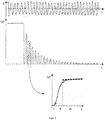
- Figure 1 shows the flow (F) and the N2 concentration over time (t).
- the patient breathes normally throughout the test, but with the nose clip on so that all air is inhaled and exhaled through the mouth.
- the N2 concentration almost constant and at the value of the ambient N2 concentration (78.08%);
- the N2 concentration is (near) zero during inspiration, and during exhalation the mean N2 concentration decreases with each breath as the nitrogen is further washed out of the lungs with each breath.
- the total expiratory nitrogen volume is determined by mathematically integrating the inspiratory and expiratory N2 concentration multiplied by the flow.
- the inhaled and exhaled N2 volume of each breath is determined and these volumes are added up to determine the total exhaled N2 volume until a threshold value for the N2 concentration is reached (usually ⁇ 2.5% of the initial concentration).
- the functional residual capacity is calculated (FRC) the total exhaled N2 volume divided by the difference between the initial end-tidal N2 concentration and the end value (threshold value) of the end-tidal N2 concentration [ Convention Declaration for Inert Gas Leaching Procedure Measurements Using Multiple and Single Breath Tests. Eur Respir J 2013; 41: 507-522 ].
- Ventilation inhomogeneity parameters are determined by a more detailed analysis of nitrogen concentration over time or over volume.
- the invention is based on the object of providing a device for measuring and analyzing multiple breath nitrogen washing processes and specifying a method for measuring and analyzing a multiple breath washing process which is improved compared to the prior art.
- the invention uses the flow and molar mass measurement with ultrasound [compare EP 0597 060 B1 , EP 0 653 919 B1 ] in combination with a fast-reacting CO2 sensor, usually based on the IR absorption method, to determine the functional residual capacity (FRC), the lung clearance index (LCI), the moment ratios, the phase III analysis (including Scond and Sacin) and other derived parameters of a nitrogen multiple breath washout test.
- FRC functional residual capacity
- LCI lung clearance index
- moment ratios including Scond and Sacin
- f x is the proportion of gas x and M x is the molar mass of gas x in g / mol.
- Equation (1) shows that the sum of all considered gas components is 100% (Dalton's law). As mentioned above, the trace gases are not taken into account here.
- Equation (2) describes the measurement of the molar mass: The molar mass measured by the ultrasonic sensor is calculated by adding up the proportions of each gas and multiplying by the respective molar mass.
- Equation (3) it is assumed that the proportion of argon is in a fixed ratio to the nitrogen proportion, so that the argon leaching is directly proportional to the nitrogen leaching. Since neither of these two gases is involved in gas exchange during human breathing, this is a valid assumption.
- the respective sensors measure the CO2 concentration (fCO2) and the molar mass (M).
- the water vapor concentration (f H2O ) in the air is determined by measuring the humidity, pressure and temperature of the room air. The concentration of water vapor in the room air can be determined from these values.
- the mechanical structure of the invention ensures during a defined water vapor concentration in the area of the sensor during the entire washout process.
- the system can be solved and the concentrations for fN2, f02 and fAr can be determined.
- the proportions fN2 and f02 can therefore be determined from the measured values for fCO2, fH2O and M.
- This correction is necessary because the measurement of the molar mass (the total molar mass M in equation (2)) is based on a fixed heat capacity ratio (see [2]).
- the device described above uses sensor technology for measuring N2 washouts in a new way.
- Build washout analyzes that can be used on a wide variety of patients (neonates to adults) and could also be adapted for use on ventilated patients.
- a flow sensor with a flow tube (1) measures the air that flows into and out of the patient's lungs.
- the flowing gas is measured in the middle of the flow sensor (at point A) in the main flow (5).
- gas concentrations cannot in most cases be measured directly in the main flow (5).
- a small proportion of the gas from the main flow is therefore sucked in via a sample tip arranged at point B.
- the secondary flow sample (6) is fed to the gas sensor (2) via a hose and then discharged via the outlet (7).
- the sample tube (4) is usually quite long and has a small diameter (eg length of 1 m with a diameter of 1 mm) so that the gas sensor can be placed at some distance from the patient. Due to the time delay caused by the transport from point B, at which the secondary flow sample gets into the hose, to point C, where the gas concentration is measured, the gas flow signals from point A and C are no longer synchronous. For an accurate multiple breath washout analysis is however, synchronicity is a prerequisite [ Convention Declaration for Inert Gas Leaching Procedure Measurements Using Multiple and Single Breath Tests. Eur Respir J 2013; 41: 507-522 ]. In addition, there is usually also a distance between point A of the flow measurement and the point at which the secondary flow sample is taken. Because of this distance, the time delay between the gas flow signal and the gas concentration signal also depends on the speed and direction of the main flow and not only on the speed of the secondary flow sample. With the embodiment of the invention described below, the two time delays are compensated for.
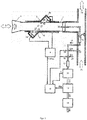
- FIG. 3 shows the block diagram of an exemplary embodiment of a system for nitrogen multiple breath washout analysis.
- the patient breathes into an ultrasonic flow and molar mass sensor (5).
- the inhaled and exhaled air (7) flows through the breathing tube (1) with mouthpiece (2), which can be exchanged and disposed of in order to avoid cross-contamination between patients.
- the flow velocity of the air as well as the molar mass in the breathing tube are determined with the help of the ultrasonic transit time measurement (transit time measurement):
- Two ultrasonic transducers (4a, 4b) send out ultrasonic pulses (6) with and against the breathing flow in the breathing tube.
- the ultrasonic impulses pass through the fine tissue (3) in the breathing tube.
- An electronic unit (9) triggers the transmission of the pulses, measures the transit times of the ultrasonic pulses upstream and downstream (4a) and (4b) and uses these transit times to calculate the flow velocity (F) and the molar mass (Mms) in the main stream [ EP 0597 060 B1 , EP 0 653 919 B1 ].
- the results for flow and molar mass in the main flow are forwarded from the electronics unit (9) to the main computing unit (15).
- the measurement and transmission frequency of these signals to the computing unit (15) is 200 Hz.
- the end of the breathing tube (1) is inserted into a T-tube.
- the patient breathes air in and out via a connection that is open to the room air (7y).
- a one-way valve (8) ensures that no gas is inhaled from the other part of the T-tube.
- oxygen breathing switched ie if the actual nitrogen washout takes place with the multiple-breath method, the patient inhales oxygen, which is supplied via the connection (7x) at constant or variable speed, and exhales again via the connection (7y).
- the flow of oxygen supplied to the connection (7x) must be greater than the patient's maximum inspiratory flow. In the clinic, oxygen can be made available via the wall connection and otherwise from an oxygen bottle.
- a sample is taken from the side stream (10).
- a pump (14) conveys the gas sample (10) through a sample hose (11) to the CO2 sensor (12) and to the molar mass sensor (13).
- the gas sample For the gas analysis, the gas sample must flow from the secondary flow through the sample hose in order to reach the gas analyzers for measuring the molar mass (13) and the CO2 (12).
- the delay caused by the transport depends on various variables (e.g. the ambient pressure, the pumping speed, etc.) and it can also differ from test to test due to slight changes in the test setup. For example, if the sample tube (11) used is an exchangeable part, the diameter and length can vary slightly from test to test.
- the inhaled and exhaled N2 volume For the multiple breath washout analysis, the inhaled and exhaled N2 volume must be determined. This is done by multiplying the nitrogen concentration by the flow rate of the main stream and then integrating it over time.
- the synchronization can be achieved by cross-correlation of the molar mass signal from the main flow (Mms) and the molar mass signal from the secondary flow (Mss).
- Mms main flow
- Mss secondary flow
- the computing unit (15) controls two valves (18) and (19). These two valves are used to switch the secondary flow between the sample connections (22), (21) and (20).
- the sample port (22) is the primary sample port used during the test.
- the sample connection (21) is only used during the calibration phase of the test. This connection is used to take samples of the gas that is supplied to the patient during the washout phase (100% oxygen). This is a first calibration point for the molar mass sensor (13).
- the sample connection (20) is only used during the calibration phase of the test. Samples of the room air are taken via this connection. This gas serves as a second calibration point for the molar mass sensor (13) and as a zero reference for the CO2 sensor (12).
- Hose material that is permeable to water vapor (16) is used to reduce the moisture (water vapor) of the bypass gas.
- the hose (16) is usually placed in the vicinity of the sample connection 22 in the area of the oxygen supply, because this reduces the risk of water condensation in the secondary flow area of the system, since the air exhaled by the patient is saturated with 100% water vapor.
- the placement within the oxygen supply reduces the amount of water vapor quite significantly, since the oxygen introduced is free of water vapor.
- Additional hose material that is permeable to water vapor (17) can be used so that the secondary flow has a defined water vapor partial pressure when it enters the gas sensors.
- This additional hose material permeable to water vapor, ensures a uniform water vapor partial pressure of all sample gas samples of the secondary flow from ports 20, 21 and 22, regardless of the fact that the sample gas from one source is free of water vapor (gas from port 21), the sample gas from the second source has the humidity of the room air (port 20) and the water vapor content the third source fluctuates (port 22).
- the innovation of the described analysis system for the multiple breath washout process consists in the calculation of the nitrogen concentration on the basis of the signals from a molar mass sensor and a conventional infrared CO2 sensor.
- Another innovation is the automatic calibration of the gas sensors with room air and with the scrubbing gas (oxygen).
- the system can be set up in a similar way, which calculates the nitrogen concentration on the basis of the signals from a molar mass sensor and a conventional O2 sensor.
Landscapes
- Health & Medical Sciences (AREA)
- Life Sciences & Earth Sciences (AREA)
- Physics & Mathematics (AREA)
- Engineering & Computer Science (AREA)
- General Health & Medical Sciences (AREA)
- Pathology (AREA)
- Biomedical Technology (AREA)
- Molecular Biology (AREA)
- Animal Behavior & Ethology (AREA)
- Heart & Thoracic Surgery (AREA)
- Public Health (AREA)
- Veterinary Medicine (AREA)
- Biophysics (AREA)
- Pulmonology (AREA)
- Medical Informatics (AREA)
- Surgery (AREA)
- Physiology (AREA)
- Chemical & Material Sciences (AREA)
- Analytical Chemistry (AREA)
- Immunology (AREA)
- General Physics & Mathematics (AREA)
- Biochemistry (AREA)
- Acoustics & Sound (AREA)
- Emergency Medicine (AREA)
- Hematology (AREA)
- Anesthesiology (AREA)
- Signal Processing (AREA)
- Obesity (AREA)
- Medicinal Chemistry (AREA)
- Food Science & Technology (AREA)
- Urology & Nephrology (AREA)
- Psychiatry (AREA)
- Computer Vision & Pattern Recognition (AREA)
- Artificial Intelligence (AREA)
- Power Engineering (AREA)
- Biodiversity & Conservation Biology (AREA)
- Nuclear Medicine, Radiotherapy & Molecular Imaging (AREA)
- Investigating Or Analysing Biological Materials (AREA)
- Measurement Of The Respiration, Hearing Ability, Form, And Blood Characteristics Of Living Organisms (AREA)
Description
- Die Erfindung betrifft ein Gerät für die Messung und Analyse des Multiple-Breath-Stickstoff-Auswaschverfahrens gemäß dem Oberbegriff des Anspruchs 1 sowie ein Verfahren zur Messung und Analyse eines Multiple-Breath-Auswaschvorgangs gemäß dem Oberbegriff des Anspruchs 9.
- Die Messung des Auswaschvorgangs von Tracergasen aus der Lunge wird seit ca. 1950 durchgeführt und wurde seitdem genutzt, um Lungenvolumen, Unterteilungen des Lungenvolumens sowie Parameter der Ventilationsinhomogenität zu bestimmen [siehe: A.A. Hutchison, A.C. Sum, T.A. Demis, A. Erben, L.I. Landau. Momentanalyse eines Multiple-Breath Stickstoff Auswaschverfahrens bei Kindern. Am Rev Respir Dis 1982; 125: 28-32]. Das Multiple-Breath-Auswaschverfahren kann mit verschiedenen Tracergasen durchgeführt werden: Helium, SF6 (Schwefelhexafluorid) oder N2 (Stickstoff) sind die am häufigsten verwendeten Tracergase. Die Verwendung von N2 ist die einfachste Methode, da der Patient dabei nur von Luftatmung auf eine Atmung mit 100 % Sauerstoff umgestellt werden muss. Während der Sauerstoffatmung wird das in der Lunge verbleibende N2 Atemzug für Atemzug aus der Lunge ausgewaschen. Zur Messung der Konzentrationen der Tracergase N2, SF6 oder Helium wurden verschiedene Verfahren entwickelt, jedes mit individuellen Vor- und Nachteilen.
- In der folgenden Beschreibung der bisher verwendeten Verfahren wird das auf Stickstoff (N2) basierende Auswaschverfahren beschrieben. Das Verfahren kann aber auf analoge Weise auch für die Analyse der Multiple-Breath-Auswaschung mit den Tracergasen SF6 oder Helium verwendet werden
- Die Analyse mit dem Stickstoff-Multiple-Breath-Auswaschverfahren (MBW) benötigt eine präzise Messung der Flussgeschwindigkeit der Gase, welche in die Lunge hinein- und herausströmen, kombiniert mit einer ebenfalls präzisen Messung der N2-Konzentrationen, welche vom Patienten ein- und ausgeatmet werden. Sowohl Flussgeschwindigkeit als auch das N2-Signal müssen mit schnell reagierenden Sensoren gemessen werden, da selbst bei Ruheatmung die Fluss- und Konzentrationssignale schnellen Änderungen unterworfen sind. Zusätzlich müssen Fluss- und N2-Konzentrationssignal synchron (d.h. ohne zeitliche Verzögerung zwischen den Signalen) aufgezeichnet werden, da zur Bestimmung der ein- und ausgeatmeten N2-Volumen das Produkt von N2-Konzentration und Fluss integriert wird.
-
Figur 1 zeigt den Fluss (F) und die N2-Konzentration über die Zeit (t). Während des gesamten Tests atmet der Patient normal, aber mit aufgesetzter Nasenklammer, damit sämtliche Luft durch den Mund ein- und ausgeatmet wird. Vor dem eigentlichen N2-Auswaschvorgang ist die N2-Konzentration nahezu konstant und auf dem Wert der N2-Umgebungskonzentration (78,08 %); während des Auswaschvorgangs ist die N2-Konzentration während der Inspiration (nahe) Null, und während der Ausatmung nimmt die mittlere N2-Konzentration mit jedem Atemzug ab, da der Stickstoff mit jedem Atemzug weiter aus der Lunge ausgewaschen wird.Figur 1 enthält ebenfalls eine vergrößerte Darstellung der N2-Konzentration über das ausgeatmete Volumen (V). Diese Darstellung veranschaulicht die Phasen I bis III einer Ausatmung (I = Totraum, II = Mischluft, III = Alveolarluft). Durch die Bestimmung der Steigung der Phase III aller Atemzüge des Auswaschvorgangs können weitere Parameter zur Quantifizierung der Ventilationsinhomogenität bestimmt werden [Übereinkommenserklärung für Inertgas-Auswaschverfahrensmessungen bei Gebrauch von Multiple- und Single-Breath-Tests. Eur Respir J 2013; 41: 507-522]. - Flussgeschwindigkeit und Gaskonzentrationssignale werden üblicherweise mit einer Messrate von 100 Hz erfasst. Strömungssensoren haben üblicherweise eine Ansprechzeit < 10 ms, die Sensoren zur Messung von Gaskonzentrationen sind meist langsamer mit Ansprechzeiten im Bereich von 60 bis 100 ms (siehe [Übereinkommenserklärung für Inertgas-Auswaschverfahrensmessungen bei Gebrauch von Multiple- und Single Breath Tests. Eur Respir J 2013; 41: 507-522]). Es stehen unterschiedliche Arten von Strömungssensoren für Gase zur Verfügung, wie z.B. Sensoren, die den Differenzdruck über einen Widerstand in der Strömungsstrecke erfassen, oder Sensoren, die das Abkühlen eines Hitzdrahtes messen, Sensoren, die die Rotation einer Turbine messen, oder Sensoren, die die Ultraschall-Laufzeit messen. Die Gaskonzentrationen unterliegen während des Auswaschvorgangs starken Schwankungen. Dies darf aber keinen Einfluss auf die Flussmessung haben oder dieser Einfluss muss ausreichend korrigiert werden. Doch nicht nur die Technik der Strömungssensoren ist unterschiedlich. Auch die Verfahren, wie die derzeitigen Systeme die Auswaschung durch Messung des Tracergases zur Bestimmung der N2-Konzentration analysieren, unterscheiden sich. Folgende Verfahren wurden zur Messung der N2-Konzentration eingesetzt:
- 1. Massenspektrometrie: Massenspektrometer können zur Messung der Gaskonzentrationen mit hoher Genauigkeit und schnellen Ansprechzeiten eingesetzt werden. Beim Multiple-Breath-Stickstoff-Auswaschverfahren werden üblicherweise die Werte der N2-, O2- und CO2-Konzentration gleichzeitig erfasst. Massenspektrometer kommen am häufigsten zum Einsatz, wenn für die Messung der Multiple-Breath-Auswaschung SF6 als Tracergas verwendet wird [P.M. Gustafsson, P. Aurora, A. Lindblad. Auswertung von fehlverteilter Beatmung als ein frühes Anzeichen für Lungenkrankheiten bei unter cystischen Fibrosen leidenden Kindern. Eur Respir J 2003; 22: 972-979]. Massenspektrometer sind sehr teuer und müssen regelmäßig gewartet werden.
- 2. Indirektes Verfahren: Durch die Verwendung zweier separater Gassensoren zur Messung der O2- und CO2-Konzentration kann die N2-Konzentration indirekt bestimmt werden. O2 wird gewöhnlich mit einem elektrochemischen Sensor oder mit Hilfe von Laserlicht durch IR-Absorption gemessen; für die CO2-Messung kommen üblicherweise IR-Absorptionssensoren zum Einsatz. Die N2-Konzentration wird indirekt anhand der O2- und CO2-Konzentration durch Anwendung des Daltonschen Gesetzes bestimmt, wonach die Summe aller Gase eines Gemischs 100% ergibt. Um eine präzise Bestimmung der N2-Konzentration sicherzustellen, müssen die O2- und CO2-Signale simultan gemessen werden, also ohne zeitliche Verzögerung zwischen den Signalen. Darüber hinaus müssen die Sensoren möglichst ähnliche Ansprechzeiten aufweisen [F. Singer, B. Houltz, P. Latzin, P. Robinson, P. Gustafsson. Eine realistische Validierungsstudie eines neuen Multiple-Breath-Stickstoff Auswaschverfahrens. PloS ONE 7(4): e36083, 2012].
- F. Singer et al. Tidal volume single breath washout of two tracer gases-a practical and promising lung function test. PLoS One, 2011, 6. Jg., Nr. 3, S. e17588 beschreibt ein Atemanalysegerät mit zwei Ultraschall-Strömungs- und Molmassensensoren (einer im Hauptstrom, einer im Nebenstrom). Dabei wird nur der im Nebenstrom angeordnete Sensor dazu genutzt, die Molmasse der strömenden Gase zu bestimmen. Darüber hinaus wird gemäß der Lehre dieser Veröffentlichung mit relativen Konzentrationen gearbeitet. So wird dort insbesondere die Korrelation von Molmassenwerten, die mittels des Ultraschall-Strömungs- und Molmassensensors erhalten wurden, mit Molmassenwerten, die mittels eines Massenspektrometers erhalten wurden, beschrieben. Allerdings wird nicht die Möglichkeit vorgesehen, dass eine Hauptrecheneinheit dazu eingerichtet ist, die Stickstoffkonzentration in dem von dem Patienten ein- und ausgeatmeten Gas auf der Grundlage der Molmasse und der CO2-Konzentration in dem von dem Patienten ein- und ausgeatmeten Gas zu berechnen.
- Liegen die synchronen Signale der N2-Konzentration und des Gasflusses vor, wird das exspiratorische Stickstoff-Gesamtvolumen durch mathematische Integration der inspiratorischen und exspiratorischen N2-Konzentration multipliziert mit dem Fluss bestimmt. Es wird also das eingeatmete und ausgeatmete N2-Volumen jedes Atemzugs bestimmt und diese Volumina werden zur Ermittlung des gesamten ausgeatmeten N2-Volumens aufaddiert, bis ein Schwellwert für die N2-Konzentration erreicht wird (gewöhnlich <2,5% der Anfangskonzentration). Schließlich wird zur Berechnung der funktionellen Residualkapazität (FRC) das gesamte ausgeatmete N2-Volumen durch die Differenz aus der anfänglichen endtidalen N2-Konzentration und dem Endwert (Schwellwert) der endtidalen N2-Konzentration geteilt [Übereinkommenserklärung für Inertgas-Auswaschverfahrensmessungen bei Gebrauch von Multiple- und Single-Breath-Tests. Eur Respir J 2013; 41: 507-522]. Parameter der Ventilationsinhomogenität (wie z.B. LCI und Momente) werden durch eine detailliertere Analyse der Stickstoffkonzentration über die Zeit oder über das Volumen bestimmt.
- Der Erfindung liegt die Aufgabe zugrunde, ein Gerät für das Messen und Analysieren von Multiple-Breath-Stickstoff-Auswaschverfahren bereitzustellen und ein gegenüber dem Stand der Technik verbessertes Verfahren zur Messung und Analyse eines Multiple-Breath-Auswaschvorgangs anzugeben.
- Diese Aufgabe wird durch ein Gerät mit den Merkmalen des Anspruchs 1 und ein Verfahren mit den Merkmalen des Anspruchs 9 gelöst.
- Bevorzugte Ausführungsformen der Erfindung gehen von den Unteransprüchen abhängend von Anspruch 1 hervor.
- Die Erfindung verwendet die Fluss- und Molmassemessung mit Ultraschall [vergleiche
EP 0597 060 B1 ,EP 0 653 919 B1 ] in Kombination mit einem schnell reagierenden CO2-Sensor, üblicherweise auf Basis des IR-Absorptionsverfahrens, zur Bestimmung der funktionellen Residualkapazität (FRC), des Lung Clearance Index (LCI), der Moment-Verhältnisse, der Phase-III-Analyse (einschliesslich Scond und Sacin) sowie weiterer, abgeleiteter Parameter eines Stickstoff-Multiple-Breath-Washout-Tests. - Vor der eigentlichen Auswaschphase, wenn der Patient Raumluft atmet, und während der Auswaschphase, wenn der Patient 100 % Sauerstoff atmet, müssen bei der Analyse folgende Gaskomponenten berücksichtigt werden:
- N2 (Stickstoff), in (trockener) Raumluft liegt die Konzentration bei etwa 78,08 %.
- 02 (Sauerstoff), in (trockener) Raumluft liegt die Konzentration bei etwa 20,95 %.
- CO2 (Kohlendioxid), in (trockener) Raumluft liegt die Konzentration bei 0,04 %, während der Ausatmung steigt sie auf etwa 4 bis 5 %.
- H2O (Wasserdampf), die Konzentration in Luft liegt, je nach Feuchtigkeit und Temperatur, zwischen 0 und etwa 5 %.
- Ar (Argon), in (trockener) Raumluft liegt die Konzentration bei etwa 0,93 %.
- Für alle anderen Gase (die sogenannten Spurengase) liegen die Konzentrationen unter 0,002 %. Diese Gase bleiben in der folgenden Diskussion unberücksichtigt.
- Während des Multiple-Breath-Auswaschvorgangs schwankt die Konzentration sämtlicher Gase im Verlauf der In- und Exspiration. Unabhängig von diesen Änderungen in der Gaskonzentration, die hauptsächlich auf die Aufnahme von Sauerstoff und die Abgabe des entstandenen Kohlendioxids zurückzuführen sind, können die drei folgenden Gleichungen aufgestellt werden:


- Hierbei ist fx der Anteil des Gases x und Mx ist die Molmasse des Gases x in g/mol.
- Gleichung (1) stellt dar, dass die Summe aller betrachteten Gasanteile 100 % ergibt (Daltonsches Gesetz). Wie oben erwähnt bleiben die Spurengase hierbei unberücksichtigt.
- Gleichung (2) beschreibt die Messung der Molmasse: Die vom Ultraschallsensor gemessene Molmasse wird errechnet durch das Aufsummieren der Anteile jedes Gases und durch Multiplizieren mit der jeweiligen Molmasse.
- In Gleichung (3) wird davon ausgegangen, dass der Anteil an Argon in einem festen Verhältnis zum Stickstoffanteil steht, dass also die Argon-Auswaschung direkt proportional zur Stickstoff-Auswaschung ist. Da keines dieser beiden Gase am Gasaustausch bei der Atmung eines Menschen beteiligt ist, ist dies eine valide Annahme.
- Die folgende Liste gibt an, welche Variablen der Gleichungen (1) bis (3) gemessen werden und welche unbekannt sind:
Gemessene Variablen: fCO2, fH2O, M Unbekannte Variablen: fN2, f02, fAr - Die jeweiligen Sensoren messen die CO2-Konzentrationen (fCO2) und die Molmasse (M). Die Wasserdampfkonzentration (fH2O) in der Luft wird durch Messung der Feuchtigkeit, des Drucks und der Temperatur der Raumluft bestimmt. Aus diesen Werten kann die Konzentration des Wasserdampfs in der Raumluft ermittelt werden. Der mechanische Aufbau der Erfindung (siehe unten) gewährleistet während des gesamten Auswaschvorgangs eine definierte Wasserdampfkonzentration im Bereich des Sensors.
- Da drei unbekannte Variablen und drei Gleichungen vorliegen, kann das System aufgelöst und die Konzentrationen für fN2, f02 und fAr können bestimmt werden. Daher lassen sich die Anteile fN2 und f02 aus den Messwerten für fCO2, fH2O und M bestimmen.
- Die aufgeführten Gleichungen gelten für alle Phasen der Stickstoffauswaschung aus der Lunge eines Patienten; sie gelten ebenso für In-vitro-Systeme, also für Systeme zur Validierung medizinischer Geräte für die Analyse der Stickstoffauswaschung; zur Simulation der Patientenlunge können sich diese Systeme einer Vorrichtung wie einer Spritze und/oder eines Behälters bedienen [F. Singer, B. Houltz, P. Latzin, P. Robinson, P. Gustafsson. Eine realistische Validierungsstudie eines neuen Multiple-Breath-Stickstoff Auswaschverfahrens. PloS ONE 7(4): e36083, 2012].
- Um eine bessere Genauigkeit zu erzielen, können die Werte für die Molmasse Mx in Gleichung (2) durch korrigierte Molmassewerte M* x ersetzt werden, wobei gilt M* x = kx * Mx und wobei es sich bei dem Faktor kx um eine dimensionslose Konstante für die adiabatische Indexkorrektur (also das Wärmekapazitätsverhältnis) handelt. Diese Korrektur ist deshalb erforderlich, weil die Messung der Molmasse (die gesamte Molmasse M in Gleichung (2)) auf einem festen Wärmekapazitätsverhältnis beruht (siehe [2]).
- Um eine hinreichende Genauigkeit in der Beurteilung des Multiple-Breath-Auswaschvorgangs zur erzielen, müssen die Werte für fN2 und f02 mit relativ hoher Genauigkeit bestimmt werden (die Genauigkeit der N2-Konzentrationsmessung sollte <0,2 % sein [Übereinkommenserklärung für Inertgas-Auswaschverfahrenmessungen bei Gebrauch von Multiple- und Single Breath Tests. Eur Respir J 2013; 41: 507-522]). In diesem Zusammenhang sollte eine Querempfindlichkeit des CO2-Sensors gegen Sauerstoff berücksichtigt werden, wenn CO2 mit Hilfe der Infrarot-Absorption gemessen wird [R. Lauber, B. Seeberger, A.M. Zbinden. Kohlenstoffdioxid-Analsysatoren: Genauigkeit, Alarmgrenzwerte und Auswirkungen eingreifender Gase. Can J Anaesth 1995, 42:7, 643-656]. Diese zusätzliche Gleichung, die eine Korrektur des gemessenen CO2-Wertes mit der berechneten Sauerstoffkonzentration durchführt, kann einfach zu den Gleichungen (1) bis (3) hinzugefügt werden.
- Das oben beschriebene Gerät nutzt gemäß der Erfindung eine Sensorentechnologie für das Messen von N2 Auswaschungen in einer neuen Art. Die Sensoren, die in dieser Ausführung genutzt werden, sind kostengünstig, haben eine hohe Langzeitstabilität, die es ermöglichen ein kosteneffektives Gerät für Multiple-Breath-Auswaschungs-Analysen zu bauen, die für eine Vielzahl von Patienten genutzt werden können (Neugeborene bis Erwachsene) und könnten auch an den Gebrauch bei ventilierten Patienten angepasst werden.
- Weitere Merkmale, Details und Vorteile der Erfindung werden detaillierter mit Referenzen zu der Ausführungsform in der Zeichnung beschrieben.
- Für die Multiple-Breath-Auswaschanalyse nutzen die meisten Systeme eine Kombination aus Haupt- und Nebenstrommessung.
Figur 2 erläutert dieses Konzept: Ein Strömungssensor mit Strömungsrohr (1) misst die Luft, die in die Lunge des Patienten und wieder herausströmt. Das strömende Gas wird in der Mitte des Strömungssensors (an der Stelle A) im Hauptstrom (5) gemessen. Da der Gassensor zu gross ist oder aufgrund von Einschränkungen im Messaufbau können Gaskonzentrationen in den meisten Fällen nicht direkt im Hauptstrom (5) gemessen werden. Ein geringer Anteil des Gases aus dem Hauptstrom wird daher über eine an der Stelle B angeordnete Probenspitze angesaugt. Mit Hilfe einer Pumpe (3) wird die Nebenstromprobe (6) über einen Schlauch dem Gassensor (2) zugeführt und anschliessend über den Auslass (7) abgeleitet. Der Probenschlauch (4) ist meist recht lang und hat einen kleinen Durchmesser (z.B. Länge von 1 m bei einem Durchmesser von 1 mm), so dass der Gassensor in einiger Entfernung zum Patienten platziert werden kann. Aufgrund der zeitlichen Verzögerung durch den Transport von Stelle B, an der die Nebenstromprobe in den Schlauch gelangt, bis Stelle C, wo die Gaskonzentration gemessen wird, sind die Gasflusssignale von Stelle A und C nicht mehr synchron. Für eine genaue Multiple-Breath-Auswaschanalyse ist die Synchronität jedoch eine Voraussetzung [Übereinkommenserklärung für Inertgas-Auswaschverfahrenmessungen bei Gebrauch von Multiple- und Single-Breath-Tests. Eur Respir J 2013; 41: 507-522]. Darüber hinaus existiert üblicherweise auch noch ein Abstand zwischen der Stelle A der Flussmessung und dem Punkt, an dem die Nebenstromprobe gezogen wird. Aufgrund dieses Abstands hängt die zeitliche Verzögerung zwischen Gasflusssignal und Gaskonzentrationssignal zusätzlich noch von der Geschwindigkeit und Richtung des Hauptstroms ab und nicht nur von der Geschwindigkeit der Nebenstromprobe. Mit der im Folgenden beschriebenen Ausgestaltung der Erfindung werden die beiden zeitlichen Verzögerungen kompensiert. -
Figur 3 zeigt das Blockdiagramm eines Ausführungsbeispiels eines Systems für die Stickstoff-Multiple-Breath-Auswaschanalyse Der Patient atmet in einen Ultraschall-Strömungs- und Molmasse-Sensor (5). Die ein- und ausgeatmete Luft (7) strömt durch das Atemrohr (1) mit Mundstück (2), das ausgetauscht und entsorgt werden kann, um eine Kreuzkontamination zwischen Patienten zu vermeiden. Die Strömungsgeschwindigkeit der Luft sowie die Molmasse im Atemrohr werden mit Hilfe der Ultraschall-Transitzeitmessung (Laufzeitmessung) ermittelt: Zwei Ultraschall-Transducer (4a, 4b) senden Ultraschallimpulse (6) mit und entgegen dem Atemstrom im Atemrohr aus. Die Ultraschallimpulse passieren das feine Gewebe (3) im Atemrohr. Eine Elektronikeinheit (9) löst die Aussendung der Impulse aus, misst die Transitzeiten der Ultraschallimpulse stromauf- und -abwärts (4a) und (4b) und berechnet anhand dieser Transitzeiten die Strömungsgeschwindigkeit (F) sowie die Molmasse (Mms) im Hauptstrom [EP 0597 060 B1 ,EP 0 653 919 B1 ]. Die Ergebnisse für Strömung und Molmasse im Hauptstrom werden von der Elektronikeinheit(9) an die Hauptrecheneinheit (15) weitergeleitet. In der aktuellen Ausgestaltung liegt die Mess- und Übertragungsfrequenz dieser Signale zur Recheneinheit (15) bei 200 Hz. - Das Ende des Atemrohrs (1) ist in ein T-Rohr eingesteckt. In der Phase vor der eigentlichen Auswaschung atmet der Patient über einen Anschluss, der offen zur Raumluft ist (7y), Luft ein und aus. Ein Einwegventil (8) stellt sicher, dass kein Gas aus dem anderen Teil des T-Rohrs eingeatmet wird. Wird auf Sauerstoffatmung umgeschaltet, d.h. wenn die eigentliche Stickstoffauswaschung mit dem Multiple-Breath-Verfahren stattfindet, atmet der Patient Sauerstoff ein, der über den Anschluss (7x) mit konstanter oder variabler Geschwindigkeit zugeführt wird, und atmet über den Anschluss (7y) wieder aus. Der Fluss des am Anschluss (7x) zugeführten Sauerstoffs muss grösser sein als der maximale Inspirationsfluss des Patienten. In der Klinik kann Sauerstoff über den Wandanschluss zur Verfügung gestellt werden und ansonsten aus einer Sauerstoffflasche. Der Patient atmet daher nur während der Auswaschphase Sauerstoff aus dem Querstrom ein; der Patient atmet während der Auswaschphase des Tests keine Raumluft ein. Für die Gasanalyse wird eine Probe aus dem Nebenstrom (10) entnommen. Eine Pumpe (14) fördert die Gasprobe (10) durch einen Probenschlauch (11) zum CO2-Sensor (12) und zum Molmassesensor (13).
- Für die Gasanalyse muss die Gasprobe aus dem Nebenstrom durch den Probenschlauch fliessen, um zu den Gasanalysatoren für die Messung der Molmasse (13) und des CO2 (12) zu gelangen. Die durch den Transport verursachte Verzögerung hängt von verschiedenen Variablen ab (z.B. vom Umgebungsdruck, von der Pumpgeschwindigkeit, usw.) und sie kann auch durch geringfügige Änderungen im Testaufbau von Test zu Test unterschiedlich sein. Wenn beispielsweise der verwendete Probenschlauch (11) ein austauschbares Teil ist, können Durchmesser und Länge von Test zu Test leicht variieren. Für die Multiple-Breath-Auswaschanalyse müssen das eingeatmete und das ausgeatmete N2-Volumen bestimmt werden. Dies geschieht durch Multiplikation der Stickstoffkonzentration mit der Flussgeschwindigkeit des Hauptstroms und anschliessender Integration über die Zeit. Die korrekte Funktionsweise dieses Verfahrens ist nur dann gewährleistet, wenn Fluss- und N2-Konzentrationssignal synchron sind; Zeitverzögerungen zwischen dem Signal der Flussgeschwindigkeit des Hauptstroms und den Gassignalen des Nebenstroms führen zu einer fehlerbehafteten Bestimmung der ein- und ausgeatmeten Gasvolumen [Übereinkommenserklärung für Inertgas-Auswaschverfahrenmessungen bei Gebrauch von Multiple- und Single-Breath-Tests. Eur Respir J 2013; 41: 507-522]. Das mit Sensor (13) gemessene Molmassesignal und das mit Sensor (12) gemessene CO2-Signal müssen daher mit dem Flussgeschwindigkeitssignal, das in der Mitte zwischen den beiden Ultraschall-Transducers (4a) und (4b) gemessen wird, synchronisiert werden. Die Synchronisation kann durch Kreuzkorrelation des Molmassesignals aus dem Hauptstrom (Mms) und dem Molmassesignal aus dem Nebenstrom (Mss) erreicht werden.Dieses Verfahren ist im Patent [
EP 1 764 036 B1 ] beschrieben; eine Anwendungsmöglichkeit für die CO-Diffusionsmessung SB (single breath, Einatemzugmethode) ist im Patent [EP 1 764 035 ] beschrieben. - Die Recheneinheit (15) steuert zwei Ventile (18) und (19). Diese beiden Ventile dienen dazu, den Nebenstromfluss zwischen den Probenanschlüssen (22), (21) und (20) umzuschalten. Der Probenanschluss (22) ist der primäre Probenanschluss, der während des Tests genutzt wird. Der Probenanschluss (21) wird nur während der Kalibrationsphase des Tests genutzt. Über diesen Anschluss werden Proben des Gases gezogen, das dem Patienten während der Auswaschphase (100 % Sauerstoff) zugeführt wird. Dies ist ein erster Kalibrationspunkt für den Molmassesensor (13). Auch der Probenanschluss (20) wird nur während der Kalibrationsphase des Tests genutzt. Über diesen Anschluss werden Proben der Raumluft gezogen. Dieses Gas dient als zweiter Kalibrationspunkt für den Molmasse-sensor (13) und als Nullreferenz für den CO2-Sensor (12).
- Weitere Elemente im Nebenstrom dienen der Aufbereitung des Gases, bevor es in die Gassensoren gelangt. Schlauchmaterial, das für Wasserdampf durchlässig ist (16), z.B. mit Nafion®-Membran, wird zur Reduzierung der Feuchtigkeit (Wasserdampf) des Nebenstromgases verwendet. Der Schlauch (16) wird üblicherweise in der Nähe des Probenanschlusses 22 im Bereich der Sauerstoffzufuhr platziert, denn dies reduziert das Risiko einer Wasserkondensation im Nebenstrombereich des Systems, da die vom Patienten ausgeatmete Luft mit 100 % Wasserdampf gesättigt ist. Die Platzierung innerhalb der Sauerstoffzufuhr reduziert die Wasserdampfmenge ganz wesentlich, da der eingeleitete Sauerstoff frei von Wasserdampf ist. Weiteres Schlauchmaterial, das für Wasserdampf durchlässig ist (17) kann eingesetzt werden, damit der Nebenstromfluss bei Eintritt in die Gassensoren einen definierten Wasserdampf-Partialdruck aufweist. Dieses zusätzliche, für Wasserdampf durchlässige Schlauchmaterial, gewährleistet einen einheitlichen Wasserdampf-Partialdruck aller Messgasproben des Nebenstroms von den Anschlüssen 20, 21 und 22, und zwar unabhängig davon, dass das Messgas der einen Quelle wasserdampffrei ist (Gas von Anschluss 21), das Messgas der zweiten Quelle die Feuchtigkeit der Raumluft aufweist (Anschluss 20) und der Wasserdampfgehalt der dritte Quelle schwankt (Anschluss 22).
- Die Neuerung des beschriebenen Analysesystems für den Multiple-Breath-Auswaschvorgang besteht in der Berechnung der Stickstoffkonzentration auf der Basis der Signale eines Molmassesensors und eines herkömmlichen Infrarot-CO2-Sensors. Eine weitere Neuerung ist die automatische Kalibrierung der Gassensoren mit Raumluft und mit dem Auswaschgas (Sauerstoff). In ähnlicher Weise kann das System aufgebaut werden, das die Stickstoffkonzentration auf der Basis der Signale eine Molmassesensors und eines herkömmlichen O2-Sensors berechnet.
Claims (10)
- Gerät zur Messung und Analyse des Multiple-Breath-Auswaschvorgangs, mit einem Strömungsrohr (1), durch das Gas von und zu der Lunge eines Patienten strömen kann und in dessen Mitte strömendes Gas in einem Hauptstrom (5) gemessen werden kann,einem ersten Ultraschall-Strömungs- und Molmassesensor (4a, 4b), der dazu dient, den momentanen Fluss und die momentane Molmasse eines von einem Patienten ein- und ausgeatmeten Gases (7) in dem Hauptstrom (5) zu messen,einem CO2-Sensor (12) in einem vom Hauptstrom (5) räumlich getrennten Nebenstrom (10), welcher einen kleinen, aus dem Hauptstrom (5) entnommenen Gasanteil darstellt, wobei der CO2-Sensor (12) dazu dient, die CO2-Konzentration in dem von dem Patienten ein- und ausgeatmeten Gas (7) zu messen,einem zweiten Ultraschall-Strömungs- und Molmassesensor (13) im Nebenstrom (10), der dazu dient, die Molmasse des von dem Patienten ein- und ausgeatmeten Gases (7) im Nebenstrom (10) zu messen,einer mit dem ersten Ultraschall-Strömungs- und Molmassesensor (4a, 4b) verbundenen Elektronikeinheit (9), die dazu dient, den Fluss und die Molmasse des von dem Patienten ein- und ausgeatmeten Gases (7) zu berechnen, undeiner mit der Elektronikeinheit (9), dem CO2-Sensor (12) und dem zweiten Ultraschall-Strömungs- und Molmassesensor (13) verbundenen Hauptrecheneinheit (15),wobei die Hauptrecheneinheit (15) dazu dient, die N2-Konzentration in dem von dem Patienten ein- und ausgeatmeten Gas (7) auf der Grundlage der Molmasse des von dem Patienten ein- und ausgeatmeten Gases (7), der CO2-Konzentration in dem von dem Patienten ein- und ausgeatmeten Gas (7) und eines vorbestimmten Werts für die Wasserdampfkonzentration durch Lösung der folgenden drei Gleichungen zu bestimmen:


 wobei fx der Anteil des Gases x und Mx die Molmasse des Gases x in g/mol ist,wobei die mit diesen Gleichungen berechnete N2-Konzentration und der gemessene Fluss des Hauptstroms für jeden Atemzug zur Bestimmung folgender Werte verwendet werden:a) des gesamten inspiratorischen und exspiratorischen Gasvolumens des Patienten durch mathematische Integration des Flusses,b) des inspiratorischen und exspiratorischen N2-Gasvolumens des Patienten durch mathematische Integration des Produkts aus inspiratorischer bzw. exspiratorischer N2-Konzentration und dem Fluss undc) von Parametern, die aus dem inspiratorischen und exspiratorischen N2-Gasvolumen und/oder dem gesamten inspiratorischen und exspiratorischen Gasvolumen abgeleitet sind und ausgewählt sind aus der Gruppe bestehend aus der funktionellen Residualkapazität, dem Lung-Clearance-Index, Momenten und Momentverhältnissen, der Phase-III-Steigung und den daraus abgeleiteten Parametern Scond und Sacin, wobeii. zur Berechnung der funktionellen Residualkapazität das gesamte ausgeatmete N2-Volumen durch die Differenz aus der anfänglichen endtidalen N2-Konzentration und dem Endwert der endtidalen N2-Konzentration geteilt wird,ii. der Lung-Clearance-Index die Anzahl der Lungendurchsätze, berechnet aus dem gesamten kumulativen exspiratorischen Gasvolumen dividiert durch die funktionelle Residualkapazität, angibt, die erforderlich sind, um die N2-Gaskonzentration auf einen bestimmten Bruchteil ihrer Ausgangskonzentration zu reduzieren,iii. die Momente das nullte Moment, das erste Moment und das zweite Moment sind, wobei das nullte Moment bestimmt wird durch Berechnung der Fläche unter einer Kurve der endtidalen Konzentration des Stickstoffs aufgetragen über die Anzahl der Lungendurchsätze, wobei das erste Moment bestimmt wird durch Berechnung der Fläche unter einer Kurve der endtidalen Konzentration des Stickstoffs multipliziert mit der Anzahl der Lungendurchsätze aufgetragen über die Anzahl der Lungenvolumendurchsätze und wobei das zweite Moment bestimmt wird durch Berechnung der Fläche unter einer Kurve der endtidalen Konzentration des Stickstoffs multipliziert mit dem Quadrat der Anzahl der Lungenvolumendurchsätze aufgetragen über die Anzahl der Lungenvolumendurchsätze,iv. die Momentverhältnisse das Verhältnis des ersten Moments zum nullten Moment sowie das Verhältnis des zweiten Moments zum nullten Moment umfassen,v. die Phase-III-Steigung die Steigung einer Kurve der N2-Konzentration aufgetragen über das gesamte exspiratorische Gasvolumen in einem Bereich von 25 % bis 75 % des gesamten exspiratorischen Gasvolumens ist,vi. Scond als lineare Regression der Phase-III-Steigungen zwischen etwa 1,5 und 6,0 Lungendurchsätzen berechnet wird,vii. Sacin drei technisch akzeptable Werte der Phase-III-Steigung für den ersten Atemzug erfordert und als der mittlere Wert der Phase-III-Steigung der drei ersten Atemzüge abzüglich des Scond-Beitrags, basierend auf dem mittleren Lungendurchsatzwert der drei ersten Atemzüge, berechnet wird.
 - Gerät nach Anspruch 1, dadurch gekennzeichnet, dass die Molmassewerte der einzelnen Gase Mx ersetzt werden durch einen Molmassewert M*x = kx * Mx, wobei es sich bei kx um eine dimensionslose Konstante für das Gas x zur adiabatischen Indexkorrektur handelt.
- Gerät nach Anspruch 1 oder 2, dadurch gekennzeichnet, dass eine O2-Querempfindlichkeit des CO2-Sensors kompensiert wird, indem die Gleichungen um eine geeignete Korrekturgleichung ergänzt werden und die Gleichungen nach N2 aufgelöst werden.
- Gerät nach einem der vorherigen Ansprüche, dadurch gekennzeichnet, dass die Hauptrecheneinheit (15) auch dazu dient, eine durch einen Transport des von dem Patienten ein- und ausgeatmeten Gases (7) aus dem Hauptstrom (1) in den Nebenstrom (10) verursachte zeitliche Verzögerung zwischen der Flussmessung im Hauptstrom (1) und der Messung der CO2-Konzentration und der Molmasse im Nebenstrom (10) durch eine Bestimmung der Verzögerung anhand einer mathematischen Kreuzkorrelation der Molmassemessung im Hauptstrom (1) und im Nebenstrom (10) zu korrigieren.
- Gerät nach einem der vorherigen Ansprüche, dadurch gekennzeichnet, dass die Hauptrecheneinheit (15) auch dazu dient, eine zusätzliche Zeitverzögerung aufgrund eines Abstands zwischen der Mitte der Flussmessung im Hauptstrom (1) und einem Punkt zur Probenentnahme (22) für den Nebenstrom (10) durch Berücksichtigung einer Verzögerungszeit zu kompensieren, wobei diese Verzögerungszeit mit einer Funktion auf Basis der Flussgeschwindigkeit des Hauptstroms (1) und der Flussrichtung berechnet wird.
- Gerät nach einem der vorherigen Ansprüche, dadurch gekennzeichnet, dass die Hauptrecheneinheit (15) auch dazu dient, unterschiedliche Ansprechzeiten des CO2-Sensors (12) sowie des ersten Ultraschall-Strömungs- und Molmassesensors (4a, 4b) und/oder des zweiten Ultraschall-Strömungs- und Molmassesensors (13) durch mathematisches Verlangsamen oder Beschleunigen der Geschwindigkeit des CO2-Sensors (12) bzw. des ersten Ultraschall-Strömungs- und Molmassesensors (4a, 4b) und/oder des zweiten Ultraschall-Strömungs- und Molmassesensors (13) zu kompensieren, um eine bei den Sensoren (12, 4a, 4b, 13) (nahezu) gleiche Ansprechzeit zu erzielen.
- Gerät nach einem der vorherigen Ansprüche, dadurch gekennzeichnet, dass die Hauptrecheneinheit (15) auch dazu dient, einen Offset des CO2-Sensors (12) automatisch mit einer der Raumluft entnommenen Gasprobe zu kalibrieren.
- Gerät nach einem der vorherigen Ansprüche, dadurch gekennzeichnet, dass die Hauptrecheneinheit (15) auch dazu dient, einen Offset und eine Verstärkung des zweiten Ultraschall-Strömungs- und Molmassesensors (13) automatisch mit Gasproben aus der Raumluft und aus reinem Sauerstoff, welcher als Auswaschgas verwendet wird, zu kalibrieren.
- Verfahren zur Messung und Analyse eines Multiple-Breath-Auswaschvorgangs unter Verwendung eines Geräts nach einem der vorhergehenden Ansprüche, umfassend die folgenden Schritte:• Messen des momentanen Flusses und der momentanen Molmasse eines von einem Patienten ein- und ausgeatmeten Gases (7) in einem Hauptstrom (1),• Messen einer CO2-Konzentration in dem von dem Patienten ein- und ausgeatmeten Gas (7) in einem Nebenstrom (10),• Messen der Molmasse des von dem Patienten ein- und ausgeatmeten Gases (7) in dem Nebenstrom (10),• Berechnen der N2-Konzentration in dem von dem Patienten ein- und ausgeatmeten Gas (7) auf der Grundlage der Molmasse des von dem Patienten ein- und ausgeatmeten Gases (7), der CO2-Konzentration in dem von dem Patienten ein- und ausgeatmeten Gas (7) und eines vorbestimmten Werts für die Wasserdampfkonzentration durch Lösung der folgenden drei Gleichungen:


- Verfahren nach Anspruch 9, dadurch gekennzeichnet, dass die N2-Konzentration in dem von dem Patienten ein- und ausgeatmeten Gas (7) mit dem gemessenen Fluss multipliziert wird und das derart erhaltene eingeatmete N2-Volumen und ausgeatmete N2-Volumen jedes Atemzugs zu einem gesamten ausgeatmeten N2-Volumen addiert werden, bis ein Schwellenwert für die N2-Konzentration erreicht wird.
Applications Claiming Priority (1)
| Application Number | Priority Date | Filing Date | Title |
|---|---|---|---|
| DE102014004765.2A DE102014004765B3 (de) | 2014-04-01 | 2014-04-01 | Gerät für die Messung und Analyse des Multiple-Breath-Stickstoff-Auswaschverfahrens |
Publications (2)
| Publication Number | Publication Date |
|---|---|
| EP2927679A1 EP2927679A1 (de) | 2015-10-07 |
| EP2927679B1 true EP2927679B1 (de) | 2021-09-29 |
Family
ID=52338852
Family Applications (1)
| Application Number | Title | Priority Date | Filing Date |
|---|---|---|---|
| EP14198579.6A Active EP2927679B1 (de) | 2014-04-01 | 2014-12-17 | Gerät für die Messung und Analyse des Multiple-Breath-Stickstoff-Auswaschverfahrens |
Country Status (4)
| Country | Link |
|---|---|
| US (1) | US20150272475A1 (de) |
| EP (1) | EP2927679B1 (de) |
| CN (1) | CN104970795B (de) |
| DE (1) | DE102014004765B3 (de) |
Families Citing this family (15)
| Publication number | Priority date | Publication date | Assignee | Title |
|---|---|---|---|---|
| EP3936178B8 (de) * | 2016-01-27 | 2025-04-30 | Beyond Air Ltd | Systeme zur inhalation eines therapeutischen gases |
| EP3457937B1 (de) * | 2016-05-15 | 2022-03-30 | Oridion Medical 1987 Ltd. | Volumetrische seitenstromkapnographie |
| US11963757B2 (en) * | 2016-06-28 | 2024-04-23 | Treymed, Inc. | Side-stream respiratory gas monitoring system |
| WO2018042152A1 (en) * | 2016-09-01 | 2018-03-08 | Oxford University Innovation Limited | Method and apparatus for quantifying lung function |
| JP6925112B2 (ja) * | 2016-10-06 | 2021-08-25 | 愛知時計電機株式会社 | 濃度計 |
| TWI621836B (zh) * | 2017-04-14 | 2018-04-21 | 貝斯美德股份有限公司 | 具有簡化結構的流量感測器 |
| DK3403578T3 (da) | 2017-05-16 | 2020-06-22 | Ndd Medizintechnik Ag | Holdeapparat til et åndedrætsrør og en fremgangsmåde til oplæsning af en kode på en overflade på åndedrætsrøret |
| WO2019074922A1 (en) * | 2017-10-10 | 2019-04-18 | Endo Medical, Inc. | BREATH ANALYSIS DEVICE |
| WO2019084225A1 (en) * | 2017-10-25 | 2019-05-02 | The University Of Vermont And State Agricultural College | METHOD AND APPARATUS FOR INTERPRETING MULTI-BREATH NITROGEN WASHING DATA |
| US20210315469A1 (en) * | 2018-08-07 | 2021-10-14 | Rostrum Medical Innovations Inc. | System and method for monitoring a blood flow that does not interact with ventilated lungs of a patient |
| DE102019119575A1 (de) * | 2019-07-18 | 2021-01-21 | Hamilton Medical Ag | Verfahren zur Ermittlung einer funktionalen Restkapazität einer Patientenlunge und Beatmungsvorrichtung zur Ausführung des Verfahrens |
| US20240237913A1 (en) * | 2021-05-11 | 2024-07-18 | Bahcesehir Universitesi | Portable breath analysis device system and a method thereof |
| DE102022111059A1 (de) * | 2022-05-04 | 2023-11-09 | Cortex Biophysik Gmbh | System zur Erfassung von Atemgasbestandteilen |
| CN118680545B (zh) * | 2024-08-29 | 2024-11-19 | 湖南欧讯医疗科技有限公司 | 一种潮气量检测系统及装置 |
| CN121613051A (zh) * | 2025-11-21 | 2026-03-06 | 北京库索深科技有限公司 | 一种油气回收设备排放气体碳排放的测定方法 |
Family Cites Families (12)
| Publication number | Priority date | Publication date | Assignee | Title |
|---|---|---|---|---|
| DE4222286C1 (de) | 1992-06-03 | 1994-05-11 | Reutter Georg Dr | Ultraschall-Spirometer |
| DE4318690A1 (de) | 1993-06-04 | 1995-01-05 | Ndd Medizintechnik Gmbh | Verfahren zur Messung der Molmasse von Gasen oder Gasgemischen und Vorrichtung zur Durchführung dieses Verfahrens |
| EP1102564A1 (de) * | 1998-08-03 | 2001-05-30 | MAULT, James R. | Verfahren und vorrichtung zur analyse von atemgas unter verwendung der messung der masse von ausgeatmetem gas |
| ES2431956T3 (es) * | 2001-01-22 | 2013-11-28 | Teijin Limited | Equipo y método para medir ultrasónicamente la concentración y el caudal de un gas |
| JP3824959B2 (ja) * | 2002-03-29 | 2006-09-20 | 本田技研工業株式会社 | 排ガスセンサの温度制御装置 |
| JP5008362B2 (ja) * | 2005-09-16 | 2012-08-22 | エンデーデー メディツィンテヒニーク アーゲー | 主流超音波フローセンサと副流ガスアナライザとの間の時間遅延を決定する装置 |
| JP2007083033A (ja) | 2005-09-16 | 2007-04-05 | Ndd Medizintechnik Ag | 肺拡散能(DLco)測定装置 |
| EP1957139B1 (de) * | 2005-12-06 | 2011-11-23 | Maquet Critical Care AB | Gerät zur schätzung des endexspiratorischen lungenvolumens |
| US7658211B1 (en) * | 2007-06-19 | 2010-02-09 | Dirst William F | Tennis ball recharging apparatus method |
| US20110245705A1 (en) * | 2008-12-09 | 2011-10-06 | Koninklijke Philips Electronics N.V. | Determining the functional residual capacity of a subject |
| PT2322917E (pt) * | 2009-11-17 | 2012-05-25 | Ndd Medizintechnik Ag | Método para a linearização de sinal de um sinal de saída de sensor de gás |
| US8603688B2 (en) * | 2010-10-27 | 2013-12-10 | GM Global Technology Operations LLC | Anode gas composition utilizing H2 injection pressure wave propagation rates |
-
2014
- 2014-04-01 DE DE102014004765.2A patent/DE102014004765B3/de active Active
- 2014-12-17 EP EP14198579.6A patent/EP2927679B1/de active Active
-
2015
- 2015-03-20 CN CN201510126725.XA patent/CN104970795B/zh not_active Expired - Fee Related
- 2015-03-31 US US14/675,569 patent/US20150272475A1/en not_active Abandoned
Also Published As
| Publication number | Publication date |
|---|---|
| US20150272475A1 (en) | 2015-10-01 |
| CN104970795A (zh) | 2015-10-14 |
| CN104970795B (zh) | 2018-09-07 |
| EP2927679A1 (de) | 2015-10-07 |
| DE102014004765B3 (de) | 2015-07-09 |
Similar Documents
| Publication | Publication Date | Title |
|---|---|---|
| DE102014004765B3 (de) | Gerät für die Messung und Analyse des Multiple-Breath-Stickstoff-Auswaschverfahrens | |
| DE3533557C2 (de) | Meßvorrichtung zur Überwachung des CO¶2¶-Gehalts, des Sauerstoffverbrauchs und des Respirationsquotienten eines Patienten | |
| EP2299901B1 (de) | Transportabler pneumotachograph zur messung von bestandteilen des exspirationsvolumens | |
| DE4118404C2 (de) | Atemgas-Strömungs-Meßsystem | |
| DE60223527T2 (de) | Verfahren und messgerät zur messung der stickoxidkonzentration in der ausatemluft | |
| DE19606470C2 (de) | Verfahren zur Bestimmung der funktionellen Residualkapazität (FRC) | |
| DE69415929T2 (de) | Verfahren und Vorrichtung zum Bestimmen des funktionellen Restvolumens der Lungen | |
| DE102008022761A1 (de) | Vorrichtung zur Gewinnung und Untersuchung von Atemgasproben | |
| DE2938856C2 (de) | ||
| DE3021326A1 (de) | Einrichtung zur messung von mindestens zwei pneumatischen lungenparametern und messverfahren hierzu | |
| EP0017162A1 (de) | Gerät zur Lungenfunktionsanalyse | |
| DE2907788A1 (de) | Stroemungsmesser fuer die zufuehrung von gasstroemungsdaten und gasproben zu einem massenspektrometer | |
| EP0874238A1 (de) | Messvorrichtung zum gleichzeitigen Bestimmen des Flusses einer strömenden Gasmischung und der Konzentration eines spezifischen Gases in der Gasmischung | |
| WO2021009215A1 (de) | Verfahren zur ermittlung einer funktionalen restkapazität einer patientenlunge und beatmungsvorrichtung zur ausführung des verfahrens | |
| DE3706074A1 (de) | Vorrichtung zum messen lokaler zerebraler blutstroeme | |
| DE2848337A1 (de) | Atemalkohol-pruefvorrichtung | |
| WO2010094414A1 (de) | Verfahren und einrichtung zur durchführung von analysen von atemgasproben | |
| DE102007012210B4 (de) | Transportabler Pneumotachograph zur Messung von Bestandteilen des Exspirationsvolumens sowie ein Verfahren hierzu | |
| EP1232393B1 (de) | Atemalkoholmessgerät | |
| DE2750450C3 (de) | Beatmungsgerät | |
| EP4210570B1 (de) | Verfahren und vorrichtung zur messung des gehalts zumindest eines gases in ausatemluft | |
| DE102006039140B4 (de) | Vorrichtung, deren Verwendung und Verfahren zum Fraktionieren des Exspirationsvolumens | |
| AT509964B1 (de) | Vorrichtung und verfahren zur bestimmung einer fertilen phase einer frau durch ermittlung eines co2-partialdruckes in einem atemgas der frau | |
| DE60103492T2 (de) | Gerät und Verfahren zur Messung des Sauerstoffverbrauchs | |
| WO2002024070A1 (de) | Gerät zur schnellen bestimmung der diffusionskapazität einer lunge |
Legal Events
| Date | Code | Title | Description |
|---|---|---|---|
| PUAI | Public reference made under article 153(3) epc to a published international application that has entered the european phase |
Free format text: ORIGINAL CODE: 0009012 |
|
| AK | Designated contracting states |
Kind code of ref document: A1 Designated state(s): AL AT BE BG CH CY CZ DE DK EE ES FI FR GB GR HR HU IE IS IT LI LT LU LV MC MK MT NL NO PL PT RO RS SE SI SK SM TR |
|
| AX | Request for extension of the european patent |
Extension state: BA ME |
|
| 17P | Request for examination filed |
Effective date: 20160303 |
|
| STAA | Information on the status of an ep patent application or granted ep patent |
Free format text: STATUS: EXAMINATION IS IN PROGRESS |
|
| 17Q | First examination report despatched |
Effective date: 20181108 |
|
| GRAP | Despatch of communication of intention to grant a patent |
Free format text: ORIGINAL CODE: EPIDOSNIGR1 |
|
| STAA | Information on the status of an ep patent application or granted ep patent |
Free format text: STATUS: GRANT OF PATENT IS INTENDED |
|
| INTG | Intention to grant announced |
Effective date: 20210421 |
|
| GRAS | Grant fee paid |
Free format text: ORIGINAL CODE: EPIDOSNIGR3 |
|
| GRAA | (expected) grant |
Free format text: ORIGINAL CODE: 0009210 |
|
| STAA | Information on the status of an ep patent application or granted ep patent |
Free format text: STATUS: THE PATENT HAS BEEN GRANTED |
|
| AK | Designated contracting states |
Kind code of ref document: B1 Designated state(s): AL AT BE BG CH CY CZ DE DK EE ES FI FR GB GR HR HU IE IS IT LI LT LU LV MC MK MT NL NO PL PT RO RS SE SI SK SM TR |
|
| REG | Reference to a national code |
Ref country code: GB Ref legal event code: FG4D Free format text: NOT ENGLISH |
|
| REG | Reference to a national code |
Ref country code: CH Ref legal event code: EP Ref country code: AT Ref legal event code: REF Ref document number: 1434623 Country of ref document: AT Kind code of ref document: T Effective date: 20211015 |
|
| REG | Reference to a national code |
Ref country code: DE Ref legal event code: R096 Ref document number: 502014015901 Country of ref document: DE |
|
| REG | Reference to a national code |
Ref country code: IE Ref legal event code: FG4D Free format text: LANGUAGE OF EP DOCUMENT: GERMAN |
|
| REG | Reference to a national code |
Ref country code: LT Ref legal event code: MG9D |
|
| PG25 | Lapsed in a contracting state [announced via postgrant information from national office to epo] |
Ref country code: HR Free format text: LAPSE BECAUSE OF FAILURE TO SUBMIT A TRANSLATION OF THE DESCRIPTION OR TO PAY THE FEE WITHIN THE PRESCRIBED TIME-LIMIT Effective date: 20210929 Ref country code: SE Free format text: LAPSE BECAUSE OF FAILURE TO SUBMIT A TRANSLATION OF THE DESCRIPTION OR TO PAY THE FEE WITHIN THE PRESCRIBED TIME-LIMIT Effective date: 20210929 Ref country code: RS Free format text: LAPSE BECAUSE OF FAILURE TO SUBMIT A TRANSLATION OF THE DESCRIPTION OR TO PAY THE FEE WITHIN THE PRESCRIBED TIME-LIMIT Effective date: 20210929 Ref country code: BG Free format text: LAPSE BECAUSE OF FAILURE TO SUBMIT A TRANSLATION OF THE DESCRIPTION OR TO PAY THE FEE WITHIN THE PRESCRIBED TIME-LIMIT Effective date: 20211229 Ref country code: LT Free format text: LAPSE BECAUSE OF FAILURE TO SUBMIT A TRANSLATION OF THE DESCRIPTION OR TO PAY THE FEE WITHIN THE PRESCRIBED TIME-LIMIT Effective date: 20210929 Ref country code: NO Free format text: LAPSE BECAUSE OF FAILURE TO SUBMIT A TRANSLATION OF THE DESCRIPTION OR TO PAY THE FEE WITHIN THE PRESCRIBED TIME-LIMIT Effective date: 20211229 Ref country code: FI Free format text: LAPSE BECAUSE OF FAILURE TO SUBMIT A TRANSLATION OF THE DESCRIPTION OR TO PAY THE FEE WITHIN THE PRESCRIBED TIME-LIMIT Effective date: 20210929 |
|
| REG | Reference to a national code |
Ref country code: NL Ref legal event code: MP Effective date: 20210929 |
|
| PG25 | Lapsed in a contracting state [announced via postgrant information from national office to epo] |
Ref country code: LV Free format text: LAPSE BECAUSE OF FAILURE TO SUBMIT A TRANSLATION OF THE DESCRIPTION OR TO PAY THE FEE WITHIN THE PRESCRIBED TIME-LIMIT Effective date: 20210929 Ref country code: GR Free format text: LAPSE BECAUSE OF FAILURE TO SUBMIT A TRANSLATION OF THE DESCRIPTION OR TO PAY THE FEE WITHIN THE PRESCRIBED TIME-LIMIT Effective date: 20211230 |
|
| PG25 | Lapsed in a contracting state [announced via postgrant information from national office to epo] |
Ref country code: IS Free format text: LAPSE BECAUSE OF FAILURE TO SUBMIT A TRANSLATION OF THE DESCRIPTION OR TO PAY THE FEE WITHIN THE PRESCRIBED TIME-LIMIT Effective date: 20220129 Ref country code: SK Free format text: LAPSE BECAUSE OF FAILURE TO SUBMIT A TRANSLATION OF THE DESCRIPTION OR TO PAY THE FEE WITHIN THE PRESCRIBED TIME-LIMIT Effective date: 20210929 Ref country code: RO Free format text: LAPSE BECAUSE OF FAILURE TO SUBMIT A TRANSLATION OF THE DESCRIPTION OR TO PAY THE FEE WITHIN THE PRESCRIBED TIME-LIMIT Effective date: 20210929 Ref country code: PT Free format text: LAPSE BECAUSE OF FAILURE TO SUBMIT A TRANSLATION OF THE DESCRIPTION OR TO PAY THE FEE WITHIN THE PRESCRIBED TIME-LIMIT Effective date: 20220131 Ref country code: PL Free format text: LAPSE BECAUSE OF FAILURE TO SUBMIT A TRANSLATION OF THE DESCRIPTION OR TO PAY THE FEE WITHIN THE PRESCRIBED TIME-LIMIT Effective date: 20210929 Ref country code: NL Free format text: LAPSE BECAUSE OF FAILURE TO SUBMIT A TRANSLATION OF THE DESCRIPTION OR TO PAY THE FEE WITHIN THE PRESCRIBED TIME-LIMIT Effective date: 20210929 Ref country code: ES Free format text: LAPSE BECAUSE OF FAILURE TO SUBMIT A TRANSLATION OF THE DESCRIPTION OR TO PAY THE FEE WITHIN THE PRESCRIBED TIME-LIMIT Effective date: 20210929 Ref country code: EE Free format text: LAPSE BECAUSE OF FAILURE TO SUBMIT A TRANSLATION OF THE DESCRIPTION OR TO PAY THE FEE WITHIN THE PRESCRIBED TIME-LIMIT Effective date: 20210929 Ref country code: CZ Free format text: LAPSE BECAUSE OF FAILURE TO SUBMIT A TRANSLATION OF THE DESCRIPTION OR TO PAY THE FEE WITHIN THE PRESCRIBED TIME-LIMIT Effective date: 20210929 Ref country code: AL Free format text: LAPSE BECAUSE OF FAILURE TO SUBMIT A TRANSLATION OF THE DESCRIPTION OR TO PAY THE FEE WITHIN THE PRESCRIBED TIME-LIMIT Effective date: 20210929 |
|
| REG | Reference to a national code |
Ref country code: DE Ref legal event code: R097 Ref document number: 502014015901 Country of ref document: DE |
|
| PG25 | Lapsed in a contracting state [announced via postgrant information from national office to epo] |
Ref country code: MC Free format text: LAPSE BECAUSE OF FAILURE TO SUBMIT A TRANSLATION OF THE DESCRIPTION OR TO PAY THE FEE WITHIN THE PRESCRIBED TIME-LIMIT Effective date: 20210929 Ref country code: DK Free format text: LAPSE BECAUSE OF FAILURE TO SUBMIT A TRANSLATION OF THE DESCRIPTION OR TO PAY THE FEE WITHIN THE PRESCRIBED TIME-LIMIT Effective date: 20210929 |
|
| PLBE | No opposition filed within time limit |
Free format text: ORIGINAL CODE: 0009261 |
|
| STAA | Information on the status of an ep patent application or granted ep patent |
Free format text: STATUS: NO OPPOSITION FILED WITHIN TIME LIMIT |
|
| GBPC | Gb: european patent ceased through non-payment of renewal fee |
Effective date: 20211229 |
|
| 26N | No opposition filed |
Effective date: 20220630 |
|
| REG | Reference to a national code |
Ref country code: BE Ref legal event code: MM Effective date: 20211231 |
|
| PG25 | Lapsed in a contracting state [announced via postgrant information from national office to epo] |
Ref country code: LU Free format text: LAPSE BECAUSE OF NON-PAYMENT OF DUE FEES Effective date: 20211217 Ref country code: IE Free format text: LAPSE BECAUSE OF NON-PAYMENT OF DUE FEES Effective date: 20211217 Ref country code: GB Free format text: LAPSE BECAUSE OF NON-PAYMENT OF DUE FEES Effective date: 20211229 |
|
| PG25 | Lapsed in a contracting state [announced via postgrant information from national office to epo] |
Ref country code: SI Free format text: LAPSE BECAUSE OF FAILURE TO SUBMIT A TRANSLATION OF THE DESCRIPTION OR TO PAY THE FEE WITHIN THE PRESCRIBED TIME-LIMIT Effective date: 20210929 Ref country code: FR Free format text: LAPSE BECAUSE OF NON-PAYMENT OF DUE FEES Effective date: 20211231 Ref country code: BE Free format text: LAPSE BECAUSE OF NON-PAYMENT OF DUE FEES Effective date: 20211231 |
|
| PG25 | Lapsed in a contracting state [announced via postgrant information from national office to epo] |
Ref country code: IT Free format text: LAPSE BECAUSE OF FAILURE TO SUBMIT A TRANSLATION OF THE DESCRIPTION OR TO PAY THE FEE WITHIN THE PRESCRIBED TIME-LIMIT Effective date: 20210929 |
|
| REG | Reference to a national code |
Ref country code: AT Ref legal event code: MM01 Ref document number: 1434623 Country of ref document: AT Kind code of ref document: T Effective date: 20211217 |
|
| PG25 | Lapsed in a contracting state [announced via postgrant information from national office to epo] |
Ref country code: AT Free format text: LAPSE BECAUSE OF NON-PAYMENT OF DUE FEES Effective date: 20211217 |
|
| PG25 | Lapsed in a contracting state [announced via postgrant information from national office to epo] |
Ref country code: HU Free format text: LAPSE BECAUSE OF FAILURE TO SUBMIT A TRANSLATION OF THE DESCRIPTION OR TO PAY THE FEE WITHIN THE PRESCRIBED TIME-LIMIT; INVALID AB INITIO Effective date: 20141217 |
|
| PG25 | Lapsed in a contracting state [announced via postgrant information from national office to epo] |
Ref country code: CY Free format text: LAPSE BECAUSE OF FAILURE TO SUBMIT A TRANSLATION OF THE DESCRIPTION OR TO PAY THE FEE WITHIN THE PRESCRIBED TIME-LIMIT Effective date: 20210929 |
|
| PG25 | Lapsed in a contracting state [announced via postgrant information from national office to epo] |
Ref country code: SM Free format text: LAPSE BECAUSE OF FAILURE TO SUBMIT A TRANSLATION OF THE DESCRIPTION OR TO PAY THE FEE WITHIN THE PRESCRIBED TIME-LIMIT Effective date: 20210929 |
|
| PG25 | Lapsed in a contracting state [announced via postgrant information from national office to epo] |
Ref country code: MK Free format text: LAPSE BECAUSE OF FAILURE TO SUBMIT A TRANSLATION OF THE DESCRIPTION OR TO PAY THE FEE WITHIN THE PRESCRIBED TIME-LIMIT Effective date: 20210929 |
|
| PG25 | Lapsed in a contracting state [announced via postgrant information from national office to epo] |
Ref country code: TR Free format text: LAPSE BECAUSE OF FAILURE TO SUBMIT A TRANSLATION OF THE DESCRIPTION OR TO PAY THE FEE WITHIN THE PRESCRIBED TIME-LIMIT Effective date: 20210929 |
|
| PG25 | Lapsed in a contracting state [announced via postgrant information from national office to epo] |
Ref country code: MT Free format text: LAPSE BECAUSE OF FAILURE TO SUBMIT A TRANSLATION OF THE DESCRIPTION OR TO PAY THE FEE WITHIN THE PRESCRIBED TIME-LIMIT Effective date: 20210929 |
|
| PGFP | Annual fee paid to national office [announced via postgrant information from national office to epo] |
Ref country code: CH Payment date: 20250101 Year of fee payment: 11 |
|
| PGFP | Annual fee paid to national office [announced via postgrant information from national office to epo] |
Ref country code: DE Payment date: 20260327 Year of fee payment: 12 |