EP2927680A2 - Verfahren zur ionendetektion - Google Patents
Verfahren zur ionendetektion Download PDFInfo
- Publication number
- EP2927680A2 EP2927680A2 EP15000961.1A EP15000961A EP2927680A2 EP 2927680 A2 EP2927680 A2 EP 2927680A2 EP 15000961 A EP15000961 A EP 15000961A EP 2927680 A2 EP2927680 A2 EP 2927680A2
- Authority
- EP
- European Patent Office
- Prior art keywords
- sample
- gas
- species
- column
- concentrator
- Prior art date
- Legal status (The legal status is an assumption and is not a legal conclusion. Google has not performed a legal analysis and makes no representation as to the accuracy of the status listed.)
- Granted
Links
- 238000000034 method Methods 0.000 title claims abstract description 97
- 238000001514 detection method Methods 0.000 title description 19
- 150000004678 hydrides Chemical class 0.000 claims abstract description 31
- 239000000126 substance Substances 0.000 claims abstract description 31
- XLYOFNOQVPJJNP-UHFFFAOYSA-N water Substances O XLYOFNOQVPJJNP-UHFFFAOYSA-N 0.000 claims abstract description 28
- 239000003638 chemical reducing agent Substances 0.000 claims abstract description 23
- 239000013626 chemical specie Substances 0.000 claims abstract description 10
- 230000002378 acidificating effect Effects 0.000 claims abstract description 9
- 239000007789 gas Substances 0.000 claims description 115
- IJGRMHOSHXDMSA-UHFFFAOYSA-N Atomic nitrogen Chemical compound N#N IJGRMHOSHXDMSA-UHFFFAOYSA-N 0.000 claims description 102
- 229910052785 arsenic Inorganic materials 0.000 claims description 50
- RQNWIZPPADIBDY-UHFFFAOYSA-N arsenic atom Chemical compound [As] RQNWIZPPADIBDY-UHFFFAOYSA-N 0.000 claims description 47
- 238000010926 purge Methods 0.000 claims description 40
- QSHDDOUJBYECFT-UHFFFAOYSA-N mercury Chemical compound [Hg] QSHDDOUJBYECFT-UHFFFAOYSA-N 0.000 claims description 34
- 229910052753 mercury Inorganic materials 0.000 claims description 34
- 239000010931 gold Substances 0.000 claims description 24
- PCHJSUWPFVWCPO-UHFFFAOYSA-N gold Chemical compound [Au] PCHJSUWPFVWCPO-UHFFFAOYSA-N 0.000 claims description 22
- 229910052737 gold Inorganic materials 0.000 claims description 22
- XEEYBQQBJWHFJM-UHFFFAOYSA-N Iron Chemical compound [Fe] XEEYBQQBJWHFJM-UHFFFAOYSA-N 0.000 claims description 19
- QVGXLLKOCUKJST-UHFFFAOYSA-N atomic oxygen Chemical compound [O] QVGXLLKOCUKJST-UHFFFAOYSA-N 0.000 claims description 19
- 239000011133 lead Substances 0.000 claims description 19
- 229910052760 oxygen Inorganic materials 0.000 claims description 19
- 239000001301 oxygen Substances 0.000 claims description 19
- 239000010453 quartz Substances 0.000 claims description 18
- VYPSYNLAJGMNEJ-UHFFFAOYSA-N silicon dioxide Inorganic materials O=[Si]=O VYPSYNLAJGMNEJ-UHFFFAOYSA-N 0.000 claims description 18
- 239000007800 oxidant agent Substances 0.000 claims description 16
- 238000010438 heat treatment Methods 0.000 claims description 15
- MHAJPDPJQMAIIY-UHFFFAOYSA-N Hydrogen peroxide Chemical compound OO MHAJPDPJQMAIIY-UHFFFAOYSA-N 0.000 claims description 14
- 239000012279 sodium borohydride Substances 0.000 claims description 14
- 229910000033 sodium borohydride Inorganic materials 0.000 claims description 14
- 229910052751 metal Inorganic materials 0.000 claims description 12
- 239000002184 metal Substances 0.000 claims description 12
- 229910052718 tin Inorganic materials 0.000 claims description 11
- OKTJSMMVPCPJKN-UHFFFAOYSA-N Carbon Chemical compound [C] OKTJSMMVPCPJKN-UHFFFAOYSA-N 0.000 claims description 10
- 229910052793 cadmium Inorganic materials 0.000 claims description 10
- BDOSMKKIYDKNTQ-UHFFFAOYSA-N cadmium atom Chemical compound [Cd] BDOSMKKIYDKNTQ-UHFFFAOYSA-N 0.000 claims description 10
- 229910052742 iron Inorganic materials 0.000 claims description 10
- 239000000758 substrate Substances 0.000 claims description 10
- 229910000497 Amalgam Inorganic materials 0.000 claims description 9
- 229910001873 dinitrogen Inorganic materials 0.000 claims description 9
- ATJFFYVFTNAWJD-UHFFFAOYSA-N Tin Chemical compound [Sn] ATJFFYVFTNAWJD-UHFFFAOYSA-N 0.000 claims description 8
- 238000005341 cation exchange Methods 0.000 claims description 7
- BUGBHKTXTAQXES-UHFFFAOYSA-N Selenium Chemical compound [Se] BUGBHKTXTAQXES-UHFFFAOYSA-N 0.000 claims description 5
- 229910052752 metalloid Inorganic materials 0.000 claims description 5
- 150000002738 metalloids Chemical class 0.000 claims description 5
- 229910052755 nonmetal Inorganic materials 0.000 claims description 5
- 229910052711 selenium Inorganic materials 0.000 claims description 5
- 239000011669 selenium Substances 0.000 claims description 5
- PORWMNRCUJJQNO-UHFFFAOYSA-N tellurium atom Chemical compound [Te] PORWMNRCUJJQNO-UHFFFAOYSA-N 0.000 claims description 5
- 229910052797 bismuth Inorganic materials 0.000 claims description 4
- MHAOVLQYUNAHGO-UHFFFAOYSA-N gold mercury Chemical compound [Au].[Hg] MHAOVLQYUNAHGO-UHFFFAOYSA-N 0.000 claims description 4
- VYZAMTAEIAYCRO-UHFFFAOYSA-N Chromium Chemical compound [Cr] VYZAMTAEIAYCRO-UHFFFAOYSA-N 0.000 claims description 3
- 229910052787 antimony Inorganic materials 0.000 claims description 3
- WATWJIUSRGPENY-UHFFFAOYSA-N antimony atom Chemical compound [Sb] WATWJIUSRGPENY-UHFFFAOYSA-N 0.000 claims description 3
- JCXGWMGPZLAOME-UHFFFAOYSA-N bismuth atom Chemical compound [Bi] JCXGWMGPZLAOME-UHFFFAOYSA-N 0.000 claims description 3
- 229910052804 chromium Inorganic materials 0.000 claims description 3
- 239000011651 chromium Substances 0.000 claims description 3
- 239000012266 salt solution Substances 0.000 claims description 3
- 229910000058 selane Inorganic materials 0.000 claims description 3
- 229910052714 tellurium Inorganic materials 0.000 claims description 3
- RWSOTUBLDIXVET-UHFFFAOYSA-N Dihydrogen sulfide Chemical compound S RWSOTUBLDIXVET-UHFFFAOYSA-N 0.000 claims description 2
- 229910000037 hydrogen sulfide Inorganic materials 0.000 claims description 2
- 229910000059 tellane Inorganic materials 0.000 claims description 2
- 239000000523 sample Substances 0.000 description 107
- 229910052757 nitrogen Inorganic materials 0.000 description 47
- 238000004817 gas chromatography Methods 0.000 description 26
- 239000007788 liquid Substances 0.000 description 21
- 230000004044 response Effects 0.000 description 20
- 230000035945 sensitivity Effects 0.000 description 16
- RBFQJDQYXXHULB-UHFFFAOYSA-N arsane Chemical compound [AsH3] RBFQJDQYXXHULB-UHFFFAOYSA-N 0.000 description 14
- 238000002347 injection Methods 0.000 description 13
- 239000007924 injection Substances 0.000 description 13
- 229910052987 metal hydride Inorganic materials 0.000 description 13
- 150000004681 metal hydrides Chemical class 0.000 description 13
- 239000000243 solution Substances 0.000 description 13
- NLKNQRATVPKPDG-UHFFFAOYSA-M potassium iodide Substances [K+].[I-] NLKNQRATVPKPDG-UHFFFAOYSA-M 0.000 description 11
- 229910000070 arsenic hydride Inorganic materials 0.000 description 10
- 150000002500 ions Chemical class 0.000 description 10
- 238000003756 stirring Methods 0.000 description 9
- 239000003610 charcoal Substances 0.000 description 8
- 230000000694 effects Effects 0.000 description 8
- 230000014759 maintenance of location Effects 0.000 description 8
- 150000001875 compounds Chemical class 0.000 description 7
- 229920000642 polymer Polymers 0.000 description 7
- 238000012360 testing method Methods 0.000 description 7
- VEXZGXHMUGYJMC-UHFFFAOYSA-N Hydrochloric acid Chemical compound Cl VEXZGXHMUGYJMC-UHFFFAOYSA-N 0.000 description 6
- 238000010791 quenching Methods 0.000 description 6
- 238000001479 atomic absorption spectroscopy Methods 0.000 description 5
- 230000008901 benefit Effects 0.000 description 5
- 238000006243 chemical reaction Methods 0.000 description 5
- 230000007246 mechanism Effects 0.000 description 5
- 238000010521 absorption reaction Methods 0.000 description 4
- 238000007796 conventional method Methods 0.000 description 4
- 238000002474 experimental method Methods 0.000 description 4
- 238000005259 measurement Methods 0.000 description 4
- 150000002739 metals Chemical class 0.000 description 4
- 230000008569 process Effects 0.000 description 4
- 230000000717 retained effect Effects 0.000 description 4
- QGJOPFRUJISHPQ-UHFFFAOYSA-N Carbon disulfide Chemical compound S=C=S QGJOPFRUJISHPQ-UHFFFAOYSA-N 0.000 description 3
- 239000005977 Ethylene Substances 0.000 description 3
- 238000010420 art technique Methods 0.000 description 3
- 238000001391 atomic fluorescence spectroscopy Methods 0.000 description 3
- 238000009616 inductively coupled plasma Methods 0.000 description 3
- 229920001343 polytetrafluoroethylene Polymers 0.000 description 3
- 239000004810 polytetrafluoroethylene Substances 0.000 description 3
- 230000000171 quenching effect Effects 0.000 description 3
- 229910001220 stainless steel Inorganic materials 0.000 description 3
- 239000010935 stainless steel Substances 0.000 description 3
- CURLTUGMZLYLDI-UHFFFAOYSA-N Carbon dioxide Chemical compound O=C=O CURLTUGMZLYLDI-UHFFFAOYSA-N 0.000 description 2
- OTMSDBZUPAUEDD-UHFFFAOYSA-N Ethane Chemical compound CC OTMSDBZUPAUEDD-UHFFFAOYSA-N 0.000 description 2
- VGGSQFUCUMXWEO-UHFFFAOYSA-N Ethene Chemical compound C=C VGGSQFUCUMXWEO-UHFFFAOYSA-N 0.000 description 2
- DGAQECJNVWCQMB-PUAWFVPOSA-M Ilexoside XXIX Chemical compound C[C@@H]1CC[C@@]2(CC[C@@]3(C(=CC[C@H]4[C@]3(CC[C@@H]5[C@@]4(CC[C@@H](C5(C)C)OS(=O)(=O)[O-])C)C)[C@@H]2[C@]1(C)O)C)C(=O)O[C@H]6[C@@H]([C@H]([C@@H]([C@H](O6)CO)O)O)O.[Na+] DGAQECJNVWCQMB-PUAWFVPOSA-M 0.000 description 2
- MWUXSHHQAYIFBG-UHFFFAOYSA-N Nitric oxide Chemical compound O=[N] MWUXSHHQAYIFBG-UHFFFAOYSA-N 0.000 description 2
- GQPLMRYTRLFLPF-UHFFFAOYSA-N Nitrous Oxide Chemical compound [O-][N+]#N GQPLMRYTRLFLPF-UHFFFAOYSA-N 0.000 description 2
- ATUOYWHBWRKTHZ-UHFFFAOYSA-N Propane Chemical compound CCC ATUOYWHBWRKTHZ-UHFFFAOYSA-N 0.000 description 2
- FAPWRFPIFSIZLT-UHFFFAOYSA-M Sodium chloride Chemical compound [Na+].[Cl-] FAPWRFPIFSIZLT-UHFFFAOYSA-M 0.000 description 2
- RAHZWNYVWXNFOC-UHFFFAOYSA-N Sulphur dioxide Chemical compound O=S=O RAHZWNYVWXNFOC-UHFFFAOYSA-N 0.000 description 2
- 238000004458 analytical method Methods 0.000 description 2
- 238000003968 anodic stripping voltammetry Methods 0.000 description 2
- 235000015197 apple juice Nutrition 0.000 description 2
- LULLIKNODDLMDQ-UHFFFAOYSA-N arsenic(3+) Chemical compound [As+3] LULLIKNODDLMDQ-UHFFFAOYSA-N 0.000 description 2
- HAYXDMNJJFVXCI-UHFFFAOYSA-N arsenic(5+) Chemical compound [As+5] HAYXDMNJJFVXCI-UHFFFAOYSA-N 0.000 description 2
- JJWKPURADFRFRB-UHFFFAOYSA-N carbonyl sulfide Chemical compound O=C=S JJWKPURADFRFRB-UHFFFAOYSA-N 0.000 description 2
- NEHMKBQYUWJMIP-UHFFFAOYSA-N chloromethane Chemical compound ClC NEHMKBQYUWJMIP-UHFFFAOYSA-N 0.000 description 2
- 239000012141 concentrate Substances 0.000 description 2
- 239000002274 desiccant Substances 0.000 description 2
- 238000013461 design Methods 0.000 description 2
- 229910002804 graphite Inorganic materials 0.000 description 2
- 239000010439 graphite Substances 0.000 description 2
- 229930195733 hydrocarbon Natural products 0.000 description 2
- 150000002430 hydrocarbons Chemical class 0.000 description 2
- 229910052739 hydrogen Inorganic materials 0.000 description 2
- 239000001257 hydrogen Chemical group 0.000 description 2
- 125000004435 hydrogen atom Chemical group [H]* 0.000 description 2
- LELOWRISYMNNSU-UHFFFAOYSA-N hydrogen cyanide Chemical compound N#C LELOWRISYMNNSU-UHFFFAOYSA-N 0.000 description 2
- 230000006872 improvement Effects 0.000 description 2
- -1 metalloids form hydrides Chemical class 0.000 description 2
- VNWKTOKETHGBQD-UHFFFAOYSA-N methane Chemical compound C VNWKTOKETHGBQD-UHFFFAOYSA-N 0.000 description 2
- 238000012986 modification Methods 0.000 description 2
- 230000004048 modification Effects 0.000 description 2
- QJGQUHMNIGDVPM-UHFFFAOYSA-N nitrogen group Chemical group [N] QJGQUHMNIGDVPM-UHFFFAOYSA-N 0.000 description 2
- 150000002843 nonmetals Chemical class 0.000 description 2
- 238000004094 preconcentration Methods 0.000 description 2
- 230000009467 reduction Effects 0.000 description 2
- 238000005070 sampling Methods 0.000 description 2
- 229910052708 sodium Inorganic materials 0.000 description 2
- 239000011734 sodium Substances 0.000 description 2
- VWDWKYIASSYTQR-UHFFFAOYSA-N sodium nitrate Chemical compound [Na+].[O-][N+]([O-])=O VWDWKYIASSYTQR-UHFFFAOYSA-N 0.000 description 2
- 238000002798 spectrophotometry method Methods 0.000 description 2
- ZSLUVFAKFWKJRC-IGMARMGPSA-N 232Th Chemical compound [232Th] ZSLUVFAKFWKJRC-IGMARMGPSA-N 0.000 description 1
- 239000010963 304 stainless steel Substances 0.000 description 1
- 239000004215 Carbon black (E152) Substances 0.000 description 1
- IAYPIBMASNFSPL-UHFFFAOYSA-N Ethylene oxide Chemical compound C1CO1 IAYPIBMASNFSPL-UHFFFAOYSA-N 0.000 description 1
- 229910000589 SAE 304 stainless steel Inorganic materials 0.000 description 1
- 229920006362 Teflon® Polymers 0.000 description 1
- 229910052776 Thorium Inorganic materials 0.000 description 1
- BZHJMEDXRYGGRV-UHFFFAOYSA-N Vinyl chloride Chemical compound ClC=C BZHJMEDXRYGGRV-UHFFFAOYSA-N 0.000 description 1
- 239000002253 acid Substances 0.000 description 1
- IYABWNGZIDDRAK-UHFFFAOYSA-N allene Chemical compound C=C=C IYABWNGZIDDRAK-UHFFFAOYSA-N 0.000 description 1
- HSFWRNGVRCDJHI-UHFFFAOYSA-N alpha-acetylene Natural products C#C HSFWRNGVRCDJHI-UHFFFAOYSA-N 0.000 description 1
- 238000013459 approach Methods 0.000 description 1
- 239000007864 aqueous solution Substances 0.000 description 1
- 238000001636 atomic emission spectroscopy Methods 0.000 description 1
- 238000000889 atomisation Methods 0.000 description 1
- 230000015572 biosynthetic process Effects 0.000 description 1
- 238000011088 calibration curve Methods 0.000 description 1
- 239000001569 carbon dioxide Substances 0.000 description 1
- 229910002092 carbon dioxide Inorganic materials 0.000 description 1
- 229910052729 chemical element Inorganic materials 0.000 description 1
- HRYZWHHZPQKTII-UHFFFAOYSA-N chloroethane Chemical compound CCCl HRYZWHHZPQKTII-UHFFFAOYSA-N 0.000 description 1
- 239000011248 coating agent Substances 0.000 description 1
- 238000000576 coating method Methods 0.000 description 1
- 239000000356 contaminant Substances 0.000 description 1
- 239000008367 deionised water Substances 0.000 description 1
- 229910021641 deionized water Inorganic materials 0.000 description 1
- 238000011161 development Methods 0.000 description 1
- 239000003651 drinking water Substances 0.000 description 1
- 235000020188 drinking water Nutrition 0.000 description 1
- 230000005684 electric field Effects 0.000 description 1
- 229960003750 ethyl chloride Drugs 0.000 description 1
- 125000002534 ethynyl group Chemical group [H]C#C* 0.000 description 1
- 235000013305 food Nutrition 0.000 description 1
- 235000011389 fruit/vegetable juice Nutrition 0.000 description 1
- 229910052732 germanium Inorganic materials 0.000 description 1
- GNPVGFCGXDBREM-UHFFFAOYSA-N germanium atom Chemical compound [Ge] GNPVGFCGXDBREM-UHFFFAOYSA-N 0.000 description 1
- 239000011521 glass Substances 0.000 description 1
- 239000011491 glass wool Substances 0.000 description 1
- IXCSERBJSXMMFS-UHFFFAOYSA-N hcl hcl Chemical compound Cl.Cl IXCSERBJSXMMFS-UHFFFAOYSA-N 0.000 description 1
- 238000001676 hydride generation atomic fluorescence spectroscopy Methods 0.000 description 1
- 150000002431 hydrogen Chemical class 0.000 description 1
- 229910052738 indium Inorganic materials 0.000 description 1
- APFVFJFRJDLVQX-UHFFFAOYSA-N indium atom Chemical compound [In] APFVFJFRJDLVQX-UHFFFAOYSA-N 0.000 description 1
- 229910052745 lead Inorganic materials 0.000 description 1
- 239000007791 liquid phase Substances 0.000 description 1
- 238000003760 magnetic stirring Methods 0.000 description 1
- 238000004949 mass spectrometry Methods 0.000 description 1
- 239000000463 material Substances 0.000 description 1
- 150000002730 mercury Chemical class 0.000 description 1
- 229940050176 methyl chloride Drugs 0.000 description 1
- 238000002156 mixing Methods 0.000 description 1
- 238000002663 nebulization Methods 0.000 description 1
- 239000006199 nebulizer Substances 0.000 description 1
- 239000001272 nitrous oxide Substances 0.000 description 1
- 150000002894 organic compounds Chemical class 0.000 description 1
- 230000003647 oxidation Effects 0.000 description 1
- 238000007254 oxidation reaction Methods 0.000 description 1
- 239000012071 phase Substances 0.000 description 1
- 238000001824 photoionisation detection Methods 0.000 description 1
- 238000001637 plasma atomic emission spectroscopy Methods 0.000 description 1
- 229910001848 post-transition metal Inorganic materials 0.000 description 1
- 239000001294 propane Substances 0.000 description 1
- QQONPFPTGQHPMA-UHFFFAOYSA-N propylene Natural products CC=C QQONPFPTGQHPMA-UHFFFAOYSA-N 0.000 description 1
- 125000004805 propylene group Chemical group [H]C([H])([H])C([H])([*:1])C([H])([H])[*:2] 0.000 description 1
- MWWATHDPGQKSAR-UHFFFAOYSA-N propyne Chemical group CC#C MWWATHDPGQKSAR-UHFFFAOYSA-N 0.000 description 1
- 150000003839 salts Chemical class 0.000 description 1
- 239000012488 sample solution Substances 0.000 description 1
- SPVXKVOXSXTJOY-UHFFFAOYSA-N selane Chemical compound [SeH2] SPVXKVOXSXTJOY-UHFFFAOYSA-N 0.000 description 1
- 239000011780 sodium chloride Substances 0.000 description 1
- 239000004317 sodium nitrate Substances 0.000 description 1
- 235000010344 sodium nitrate Nutrition 0.000 description 1
- 239000007787 solid Substances 0.000 description 1
- 238000010183 spectrum analysis Methods 0.000 description 1
- 230000003068 static effect Effects 0.000 description 1
- 238000012549 training Methods 0.000 description 1
- 229910052723 transition metal Inorganic materials 0.000 description 1
- 150000003624 transition metals Chemical class 0.000 description 1
- 238000013022 venting Methods 0.000 description 1
- 230000004304 visual acuity Effects 0.000 description 1
- 239000002699 waste material Substances 0.000 description 1
Images


Classifications
-
- G—PHYSICS
- G01—MEASURING; TESTING
- G01N—INVESTIGATING OR ANALYSING MATERIALS BY DETERMINING THEIR CHEMICAL OR PHYSICAL PROPERTIES
- G01N30/00—Investigating or analysing materials by separation into components using adsorption, absorption or similar phenomena or using ion-exchange, e.g. chromatography or field flow fractionation
- G01N30/02—Column chromatography
- G01N30/62—Detectors specially adapted therefor
- G01N30/64—Electrical detectors
-
- G—PHYSICS
- G01—MEASURING; TESTING
- G01N—INVESTIGATING OR ANALYSING MATERIALS BY DETERMINING THEIR CHEMICAL OR PHYSICAL PROPERTIES
- G01N27/00—Investigating or analysing materials by the use of electric, electrochemical, or magnetic means
- G01N27/62—Investigating or analysing materials by the use of electric, electrochemical, or magnetic means by investigating the ionisation of gases, e.g. aerosols; by investigating electric discharges, e.g. emission of cathode
- G01N27/64—Investigating or analysing materials by the use of electric, electrochemical, or magnetic means by investigating the ionisation of gases, e.g. aerosols; by investigating electric discharges, e.g. emission of cathode using wave or particle radiation to ionise a gas, e.g. in an ionisation chamber
-
- G—PHYSICS
- G01—MEASURING; TESTING
- G01N—INVESTIGATING OR ANALYSING MATERIALS BY DETERMINING THEIR CHEMICAL OR PHYSICAL PROPERTIES
- G01N30/00—Investigating or analysing materials by separation into components using adsorption, absorption or similar phenomena or using ion-exchange, e.g. chromatography or field flow fractionation
- G01N30/02—Column chromatography
- G01N30/04—Preparation or injection of sample to be analysed
- G01N30/06—Preparation
-
- G—PHYSICS
- G01—MEASURING; TESTING
- G01N—INVESTIGATING OR ANALYSING MATERIALS BY DETERMINING THEIR CHEMICAL OR PHYSICAL PROPERTIES
- G01N30/00—Investigating or analysing materials by separation into components using adsorption, absorption or similar phenomena or using ion-exchange, e.g. chromatography or field flow fractionation
- G01N30/02—Column chromatography
- G01N30/26—Conditioning of the fluid carrier; Flow patterns
- G01N30/28—Control of physical parameters of the fluid carrier
- G01N30/30—Control of physical parameters of the fluid carrier of temperature
-
- G—PHYSICS
- G01—MEASURING; TESTING
- G01N—INVESTIGATING OR ANALYSING MATERIALS BY DETERMINING THEIR CHEMICAL OR PHYSICAL PROPERTIES
- G01N30/00—Investigating or analysing materials by separation into components using adsorption, absorption or similar phenomena or using ion-exchange, e.g. chromatography or field flow fractionation
- G01N30/02—Column chromatography
- G01N30/88—Integrated analysis systems specially adapted therefor, not covered by a single one of the groups G01N30/04 - G01N30/86
-
- G—PHYSICS
- G01—MEASURING; TESTING
- G01N—INVESTIGATING OR ANALYSING MATERIALS BY DETERMINING THEIR CHEMICAL OR PHYSICAL PROPERTIES
- G01N33/00—Investigating or analysing materials by specific methods not covered by groups G01N1/00 - G01N31/00
- G01N33/0004—Gaseous mixtures, e.g. polluted air
- G01N33/0009—General constructional details of gas analysers, e.g. portable test equipment
- G01N33/0011—Sample conditioning
- G01N33/0013—Sample conditioning by a chemical reaction
-
- G—PHYSICS
- G01—MEASURING; TESTING
- G01N—INVESTIGATING OR ANALYSING MATERIALS BY DETERMINING THEIR CHEMICAL OR PHYSICAL PROPERTIES
- G01N33/00—Investigating or analysing materials by specific methods not covered by groups G01N1/00 - G01N31/00
- G01N33/0004—Gaseous mixtures, e.g. polluted air
- G01N33/0009—General constructional details of gas analysers, e.g. portable test equipment
- G01N33/0011—Sample conditioning
- G01N33/0019—Sample conditioning by preconcentration
-
- G—PHYSICS
- G01—MEASURING; TESTING
- G01N—INVESTIGATING OR ANALYSING MATERIALS BY DETERMINING THEIR CHEMICAL OR PHYSICAL PROPERTIES
- G01N33/00—Investigating or analysing materials by specific methods not covered by groups G01N1/00 - G01N31/00
- G01N33/0004—Gaseous mixtures, e.g. polluted air
- G01N33/0009—General constructional details of gas analysers, e.g. portable test equipment
- G01N33/0027—General constructional details of gas analysers, e.g. portable test equipment concerning the detector
- G01N33/0036—General constructional details of gas analysers, e.g. portable test equipment concerning the detector specially adapted to detect a particular component
- G01N33/0045—Hg
-
- G—PHYSICS
- G01—MEASURING; TESTING
- G01N—INVESTIGATING OR ANALYSING MATERIALS BY DETERMINING THEIR CHEMICAL OR PHYSICAL PROPERTIES
- G01N30/00—Investigating or analysing materials by separation into components using adsorption, absorption or similar phenomena or using ion-exchange, e.g. chromatography or field flow fractionation
- G01N2030/009—Extraction
-
- G—PHYSICS
- G01—MEASURING; TESTING
- G01N—INVESTIGATING OR ANALYSING MATERIALS BY DETERMINING THEIR CHEMICAL OR PHYSICAL PROPERTIES
- G01N30/00—Investigating or analysing materials by separation into components using adsorption, absorption or similar phenomena or using ion-exchange, e.g. chromatography or field flow fractionation
- G01N30/02—Column chromatography
- G01N2030/022—Column chromatography characterised by the kind of separation mechanism
- G01N2030/025—Gas chromatography
-
- G—PHYSICS
- G01—MEASURING; TESTING
- G01N—INVESTIGATING OR ANALYSING MATERIALS BY DETERMINING THEIR CHEMICAL OR PHYSICAL PROPERTIES
- G01N30/00—Investigating or analysing materials by separation into components using adsorption, absorption or similar phenomena or using ion-exchange, e.g. chromatography or field flow fractionation
- G01N30/02—Column chromatography
- G01N30/04—Preparation or injection of sample to be analysed
- G01N30/06—Preparation
- G01N2030/067—Preparation by reaction, e.g. derivatising the sample
-
- G—PHYSICS
- G01—MEASURING; TESTING
- G01N—INVESTIGATING OR ANALYSING MATERIALS BY DETERMINING THEIR CHEMICAL OR PHYSICAL PROPERTIES
- G01N30/00—Investigating or analysing materials by separation into components using adsorption, absorption or similar phenomena or using ion-exchange, e.g. chromatography or field flow fractionation
- G01N30/02—Column chromatography
- G01N30/04—Preparation or injection of sample to be analysed
- G01N30/06—Preparation
- G01N30/08—Preparation using an enricher
- G01N2030/085—Preparation using an enricher using absorbing precolumn
-
- G—PHYSICS
- G01—MEASURING; TESTING
- G01N—INVESTIGATING OR ANALYSING MATERIALS BY DETERMINING THEIR CHEMICAL OR PHYSICAL PROPERTIES
- G01N30/00—Investigating or analysing materials by separation into components using adsorption, absorption or similar phenomena or using ion-exchange, e.g. chromatography or field flow fractionation
- G01N30/02—Column chromatography
- G01N30/04—Preparation or injection of sample to be analysed
- G01N30/06—Preparation
- G01N30/14—Preparation by elimination of some components
- G01N2030/143—Preparation by elimination of some components selective absorption
-
- G—PHYSICS
- G01—MEASURING; TESTING
- G01N—INVESTIGATING OR ANALYSING MATERIALS BY DETERMINING THEIR CHEMICAL OR PHYSICAL PROPERTIES
- G01N30/00—Investigating or analysing materials by separation into components using adsorption, absorption or similar phenomena or using ion-exchange, e.g. chromatography or field flow fractionation
- G01N30/02—Column chromatography
- G01N30/62—Detectors specially adapted therefor
- G01N30/64—Electrical detectors
- G01N2030/642—Electrical detectors photoionisation detectors
-
- G—PHYSICS
- G01—MEASURING; TESTING
- G01N—INVESTIGATING OR ANALYSING MATERIALS BY DETERMINING THEIR CHEMICAL OR PHYSICAL PROPERTIES
- G01N30/00—Investigating or analysing materials by separation into components using adsorption, absorption or similar phenomena or using ion-exchange, e.g. chromatography or field flow fractionation
- G01N30/02—Column chromatography
- G01N30/88—Integrated analysis systems specially adapted therefor, not covered by a single one of the groups G01N30/04 - G01N30/86
- G01N2030/8809—Integrated analysis systems specially adapted therefor, not covered by a single one of the groups G01N30/04 - G01N30/86 analysis specially adapted for the sample
- G01N2030/8868—Integrated analysis systems specially adapted therefor, not covered by a single one of the groups G01N30/04 - G01N30/86 analysis specially adapted for the sample elemental analysis, e.g. isotope dilution analysis
-
- G—PHYSICS
- G01—MEASURING; TESTING
- G01N—INVESTIGATING OR ANALYSING MATERIALS BY DETERMINING THEIR CHEMICAL OR PHYSICAL PROPERTIES
- G01N30/00—Investigating or analysing materials by separation into components using adsorption, absorption or similar phenomena or using ion-exchange, e.g. chromatography or field flow fractionation
- G01N30/02—Column chromatography
- G01N30/88—Integrated analysis systems specially adapted therefor, not covered by a single one of the groups G01N30/04 - G01N30/86
- G01N2030/8809—Integrated analysis systems specially adapted therefor, not covered by a single one of the groups G01N30/04 - G01N30/86 analysis specially adapted for the sample
- G01N2030/8872—Integrated analysis systems specially adapted therefor, not covered by a single one of the groups G01N30/04 - G01N30/86 analysis specially adapted for the sample impurities
-
- G—PHYSICS
- G01—MEASURING; TESTING
- G01N—INVESTIGATING OR ANALYSING MATERIALS BY DETERMINING THEIR CHEMICAL OR PHYSICAL PROPERTIES
- G01N27/00—Investigating or analysing materials by the use of electric, electrochemical, or magnetic means
- G01N27/62—Investigating or analysing materials by the use of electric, electrochemical, or magnetic means by investigating the ionisation of gases, e.g. aerosols; by investigating electric discharges, e.g. emission of cathode
- G01N27/626—Investigating or analysing materials by the use of electric, electrochemical, or magnetic means by investigating the ionisation of gases, e.g. aerosols; by investigating electric discharges, e.g. emission of cathode using heat to ionise a gas
- G01N27/628—Investigating or analysing materials by the use of electric, electrochemical, or magnetic means by investigating the ionisation of gases, e.g. aerosols; by investigating electric discharges, e.g. emission of cathode using heat to ionise a gas and a beam of energy, e.g. laser enhanced ionisation
-
- G—PHYSICS
- G01—MEASURING; TESTING
- G01N—INVESTIGATING OR ANALYSING MATERIALS BY DETERMINING THEIR CHEMICAL OR PHYSICAL PROPERTIES
- G01N30/00—Investigating or analysing materials by separation into components using adsorption, absorption or similar phenomena or using ion-exchange, e.g. chromatography or field flow fractionation
- G01N30/96—Investigating or analysing materials by separation into components using adsorption, absorption or similar phenomena or using ion-exchange, e.g. chromatography or field flow fractionation using ion-exchange
Definitions
- the present invention relates generally to the detection of species ionized by radiant energy. Particularly, the present invention relates to a method of detecting hydrides or mercury ionized by radiant energy using photoionization.
- Photoionization as a scientific concept has been known for some time.
- the first application of photoionization detection was as a gas chromatography (GC) ion detector for hydrocarbons.
- a photoionization detector high-energy photons, typically in the ultraviolet (far UV) range, break molecules into positively charged ions.
- compounds elute from the GC's column they are bombarded by high-energy photons and are ionized when molecules absorb high energy UV light.
- UV light excites the molecules, resulting in temporary loss of electrons in the molecules and the formation of positively charged ions.
- the gas becomes electrically charged and the ions produce an electric current, which is the signal output of the detector.
- the greater the concentration of the component the more ions are produced, and the greater the current.
- the photoionization process is initiated when a photon of sufficient energy (from a short wavelength UV lamp) is absorbed by a molecule.
- a photon of sufficient energy from a short wavelength UV lamp
- the ions (R + ) formed by absorption of the UV photons are collected by applying a positive potential (100-200 V) to the accelerating electrode and measuring the current at the collection electrode.
- the current produced is proportional to the concentration over a very wide range.
- Hydride generation is a procedure commonly used for sensitivity enhancement in a variety of instrumental methods for measuring trace levels of As, Se, Sb, Sn, Ge, Te, and Bi (and sometimes Pb) in aqueous solutions and wet-ashed solid samples.
- a hydride is a compound in which one or more hydrogen atoms have reducing, or basic properties. In hydrides, hydrogen is bonded to a more electropositive element such as a metal. When metal hydride forming compounds in solution are treated with a reducing agent, the hydride MH 3 (g) is formed.
- the hydride technique typically results in several orders of magnitude improvement in concentration sensitivity over conventional nebulizer sample introduction.
- the two instrumental methods most commonly coupled to hydride preconcentration are atomic absorption and plasma emission spectrometry.
- solution-phase concentration detection limits in the range of 0.2-0.4 ppb As, Se, and Sn can be routinely achieved.
- liquid nitrogen was used to preconcentrate the sample.
- a photoionization detector (PID) and a liquid nitrogen cold trap (i.e. a concentrator) provides several orders of magnitude of sensitivity improvement over the best existing continuous-flow hydride generation atomic absorption and plasma emission systems for As, Se, and Sn determination (without suffering any significant selenium hydride loss).
- the present invention achieves these and other objectives by providing a method for detecting ionized species that includes, in one embodiment, hydride generation, and in another embodiment, an ionizable gas of an element, and directly measuring a hydride species or the ionizable gas of an element, respectively, using a photoionization detector without using a liquid nitrogen trap.
- the method includes providing providing in a vessel an acidic sample containing an ionic chemical species to be measured where a substrate of the species to be formed is ionizable by radiant energy provided by a photoionization detector in the detector system and where the vessel has a headspace above the acidic sample, adding a preselected reducing agent to the aqueous sample and forming an ionizable chemical gas species in the aqueous sample whereby the ionizable chemical gas species evolves out of the aqueous sample and into the headspace forming a gas sample, moving the gas sample containing the ionizable chemical gas species from the headspace of the vessel out of the vessel and through a precolumn, and moving the gas sample containing the ionizable chemical gas species from the precolumn into one of (1) a photoionization detector or a gas chromatograph having a photoionization detector when the headspace is purged with nitrogen gas prior to performing the adding step, or, when the headspace contained
- the method includes selecting a column that receives the gas sample from the group consisting of a packed column, a PLOT column, or a capillary column before being ionized by radiant energy using PID.
- the method includes selecting one of a capillary column that is a thick film capillary column or selecting a PLOT column packed with a porous polymer.
- the method includes selecting an ionic sample having one or more of a metal, nonmetal or metalloid that forms a hydride.
- the method includes selecting a sample having one or more ionic species selected from the group consisting of arsenic, antimony, cadmium, lead, iron, chromium, selenium, tellurium, bismuth, tin, mercury, hydrogen selenide, and hydrogen telluride.
- the method includes selecting an aqueous sample having an ionic species wherein a substrate of the ionic species has an ionization potential in the range of 8-12 eV.
- the method includes selecting sodium borohydride or Sn-HCl as the reducing agent.
- the method further includes adding an oxidizing agent to the ionic sample for metals such as Pb or Fe and others.
- the oxidizing agent is hydrogen peroxide.
- the method includes passing a predefined quantity of aqueous ionic sample containing the ionic species through a cation exchange column and desorbing the ionic species from the cation exchange column with smaller predefined quantity of a salt solution before placing the sample in the vessel.
- the method includes passing the gas sample through a concentrator column to accumulate the ionizable chemical gas species in the concentrator column before moving the gas sample into the photoionization detector or a gas chromatograph having a photoionization detector. After a predefined time accumulating the ionizable chemical gas species in the concentrator column, the column is then quickly heated to a predefined temperature to release the ionizable chemical gas species. The the released ionizable chemical gas species is then passed into the photoionization detector or a gas chromatograph having a photoionization detector.
- the method includes selecting a concentrator column that contains (1) activated charcoal when the ionizable chemical gas species is an ionizable gas hydride substrate of the chemical species or (2) gold film when the ionizable chemical gas species is mercury.
- the heating step includes heating to a temperature of 150°C in about 1 to about 2 minutes.
- the concentrator column contains gold film, the heating step includes heating to 500°C in about 30 seconds.
- the method includes selecting a vessel that is a sparger.
- the method includes selecting a vessel that is a VOA vial with a septum and no headspace above the acidic sample and removing a predefined quantity of the sample from the vessel through the septum creating the headspace.
- the method further includes stirring the aqueous sample when adding the preselected reducing agent and continuing the stirring until eluting of the gas sample is complete.
- a method for detecting mercury in air by a photoionization detector system includes passing a substantial quantity of air through a concentrator column containing gold film whereby a gold-mercury amalgam is formed, purging the concentrator with nitrogen gas for a predefined period of time to remove oxygen and other organics from the concentrator quickly heating the gold film concentrator to a substantial temperature (500 °C) to decompose the gold-mercury amalgam forming mercury gas, and injecting the mercury gas into a photoionization detector system.
- the concentrator column is heated to 500°C in about 30 seconds.
- the concentrator for mercury whether used for air or aqueous sampling.
- the concentrator has a quartz body with a concentrator inlet connected to a first body end, a concentrator outlet connected transversely to the quartz body, a heater end connected to a second body end, and a stainless steel rod coated with a gold film disposed within the quartz body and extending out of the heater end a predefined distance.
- the advantages of the present invention is that it is easy to use, does not require a high level of training, and has a low capital cost.
- a "precolumn” means a six inch (15.24 cm) length of a column packed with a porous polymer or a short thick film capillary column.
- An example of an acceptable porous polymer is the porous polymer sold under the trademark HayeSep® N.
- oxygen-retaining column means a packed column or a PLOT column or a capillary column of sufficient length where the retention time of oxygen in the column is longer than the retention time for an ionizable chemical gas species.
- an "ionizable chemical gas species” means an ionizable gas hydride substrate of the chemical species or an ionizable gas of a chemical element of the chemical species.
- the PID detector is used for hydrocarbon detection.
- Other techniques are typically used for transition metals, post-transition metals and metalloids.
- the most popular techniques that are typically used include hydride generation with atomic absorption spectrometry (HGAAS) or atomic fluorescence spectrometry (HGAFS), graphite furnace atomization with AAS detection (GFAAS) to improve sensitivity, inductively coupled plasma with optical emission spectrometry (ICP-OES), inductively coupled plasma with mass spectrometry (ICP-MS) with ultrasonic nebulization, anodic stripping voltammetry (ASV), and spectrophotometry.
- HGAAS atomic absorption spectrometry
- HAFS atomic fluorescence spectrometry
- GFAAS graphite furnace atomization with AAS detection
- ICP-OES inductively coupled plasma with optical emission spectrometry
- ICP-MS inductively coupled plasma with mass spectrometry
- ASV anodic stripping
- the typical GC/PID method involves collecting the AsH 3 in a liquid nitrogen trap (glass U-tube packed with silanized glass wool), and then the collected AsH 3 is removed from the liquid nitrogen trap by applying heat to re-volatize the arsine, which is then swept into the GC with a packed column. The flow of nitrogen gas is continues throughout the GC/PID method.
- Figure 17 illustrates a schematic of the GC/PID method with the liquid nitrogen trap.
- the method includes adding sample to a sparger 1, which is a vessel 1a having a typical capacity of 70-100 cc and that has an inlet 2 and an outlet 3 and an injection port 4 (septum) to inject a liquid sample into vessel 1a.
- a reducing agent such as 4% sodium borahydride
- the metal salt (MO 3 -3 ) i.e. the ionic species
- MH x metal hydride
- the liquid sample 5 is continuously purged with nitrogen gas (N 2 ) through inlet 2 to agitate the liquid sample 5 and to remove MH 3 gas from the liquid sample 5 and the head space 6 and elute it to a water vapor trap 7 having a temperature of about -50 degrees centigrade before eluting to a liquid nitrogen trap 8 containing a U-tube 8a where the MH 3 gas is cooled and trapped.
- N 2 nitrogen gas
- the trapped metal hydride is heated rapidly and desorbed into an Atomic Absorption spectrometer or a GC 9.
- a six-way valve 8b is typically used to facilitate sample handling prior to injection into the AA or GC 9.
- Quenching by water is due to the same mechanism as described above for O 2 .
- water absorbs photons strongly at 120 nm thereby reducing the number of photons available for photoionization.
- water must also be removed from the nitrogen stream used in the prior art, which is typically done with a separate cold trap 7 as shown in Figure 17 or a drying agent (not shown) prior to the nitrogen stream containing the metal hydride entering the liquid nitrogen trap.
- the present invention includes hydride generation by adding an acid solution (e.g., 0.6 M HCl) to the aqueous sample, then adding the reducing agent (e.g., NaBH 4 ).
- the present invention differs from the prior art techniques in the method of generating and preparing the ionic species and/or a substrate of the ionic species for injection into a PID or a GC/PID.
- a non-continuous purge of nitrogen into the vessel is used.
- a continuous purge of nitrogen into the vessel may be used.
- the present invention differs from the prior art techniques by the absence of (i.e. without the use of) a liquid nitrogen trap.
- the present invention differs from the prior art techniques by the absence of a heated desorbing step.
- no liquid nitrogen trap is used in the method of the present invention, which is required in the prior art to concentrate the metal hydride flowing in the continuous stream of nitrogen gas eluting from the vessel that must then be rapidly heated to re-volatize the metal hydride before injecting into the PID or GC/PID.
- the present invention does not require a separate concentrator except for certain low level ppt measurements of particular species.
- the reaction vessel used in the present invention for hydride generation may be either a sparger or a VOA vial, which is discussed later.
- the sparger is a vessel having about an 80 cc capacity with an inlet, an outlet and a septum for the addition of a reducing agent and, optionally, an oxidizing agent.
- a stirring mechanism such as, for example, a magnetic stirrer, is optionally and preferably used to agitate the solution and to more quickly drive the MH 3 gas into the headspace of the vessel. Because oxygen will quench the PID response, nitrogen gas is used to purge the sample and the headspace of oxygen and prepare the sample for the generation of the MH 3 gas especially when low parts-per-billion levels need to be measured.
- the nitrogen purge is typically performed for several minutes and then stopped.
- a reducing agent and, optionally, an oxidizing agent is added to the acidic aqueous sample depending on the species in the aqueous sample.
- a reducing agent such as sodium borohydride (NaBH 4 )
- NaBH 4 sodium borohydride
- the amount of NaBH 4 added to the aqueous sample is in the range of about 4%. The higher end being required for low ppb levels of the species to be measured in the aqueous sample.
- the inclusion of the oxidizing agent is provided in some cases such as, for example, iron or lead, to oxidize the sample to Fe +3 from Fe +2 or Pb +4 from Pb +2 .
- An example of an oxidizing agent is hydrogen peroxide (H 2 O 2 ).
- H 2 O 2 hydrogen peroxide
- magnetic stirring is preferably used to agitate the sample containing the reducing agent and/or the oxidizing agent and to quickly release the MH x gas from the aqueous sample.
- the nitrogen purge is then stopped for a predefined time before eluting the gas sample from the sparger.
- the gas sample may be eluted manually or by an automatic injection system.
- a predefined time (depending on the levels to be detected) after the nitrogen purge is stopped passes before a predefined quantity (preferably about 1 cc) of the MH x gas is eluted from the headspace of the sparger to or injected into the PID detector or the GC with the photoionization detector.
- a predefined quantity preferably about 1 cc
- the predefined time is about 2-6 minutes.
- the increase in sensitivity from a 2 minute sample to a 5 minute sample can be from 3-5 times.
- the predefined time is about 10-12 minutes.
- the signal is severely quenched, however, when a GC is used, the GC separates the metal-related signal from the water vapor signal. It is noted that the nitrogen purge may be continuous provided that other mechanisms as described herein are used to concentrate the metal of the MH 3 , particularly when low ppb or lower levels are to be detected.
- the MH 3 gas may optionally be passed through (1) an oxygen-retaining column before being injected into the PID or the GC/PID or (2) a precolumn before being injected into the PID or the GC/PID or (3) both an oxygen-retaining column and a precolumn before being injected into the PID or the GC/PID, as the case may be depending on an initial content of a headspace in the reaction vessel.
- the column is one of a packed column, a porous layer open tubular (PLOT) column or a capillary column.
- the packed column is preferably one that is a 1/8" (0.32 cm) column, six feet (182.9 cm) long and packed with porous polymer sold under the trademark Tenax® GS or Chromsorb® or Hayesep® or Poropak®. For a packed column, nitrogen purging for several minutes may be necessary to remove O 2 at low part-per-billion (ppb) concentrations.
- the PLOT column is packed with a porous polymer.
- the most preferred column to be optionally used is the capillary column.
- the preferred capillary column is a thick film capillary column since it not only can be used for aqueous samples but is better for analysis of foods and juices that contain significant levels of organic compounds.
- capillary column would be a 30 meter x 0.53 mm with various liquid phases.
- the "thick film” is typically 0.32 mm thick with 3-8 micron films.
- the improved sensitivity is about ten times better due to the very sharp peaks and improved resolving power.
- packed columns may also be used but the peaks are wider and the detection limits may require a considerably larger sample on the order of about 5-10 CC.
- the PLOT column and the capillary column are available from various scientific equipment suppliers known to those skilled in the art.
- O 2 will be separated from the MH 3 gas so the sparger containing the aqueous sample does not have to be purged.
- the method of the present invention does not need a water trap or chiller when the optional precolumn (discussed later) is used.
- a sample is passed through an optional cation exchange column to collect the sample.
- the sample is then desorbed with a salt solution where the sample is now concentrated by a factor of 10.
- about 250 cc of 1 ppb sample is collected and then desorbed with 10 cc of 0.1 M sodium chloride solution.
- the sample is desorbed with about 25 cc of 0.1 M sodium nitrate solution.
- directly injecting 1 cc of the substrate of the ionic species is sufficient to detect low or sub parts-per-billion levels.
- the method of the present invention is capable of measuring various species including, but not limited to, arsenic, antimony, cadmium, lead, iron, chromium, germanium, indium, thorium, selenium, tellurium, bismuth, tin, and mercury, to name a few. Unlike arsenic, many of the other species have sensitivities much lower. The range is 10 to 100 times lower. For these species, a concentration step such as the use of the cation exchange column may be performed to detect low parts-per-billion levels.
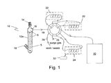
- FIG. 1 schematically illustrates a system that uses the method of the present invention when using a detector system 10, which is either a PID detector or a GC equipped with a PID detector.
- a detector system 10 which is either a PID detector or a GC equipped with a PID detector.
- This illustration includes a vessel 12 that is a sparger in this illustration, a gas input 14, a gas output 16 and port 18 for receiving a liquid sample 5 and/or a reducing agent and/or an oxidizing agent.
- the gas output 16 is connected to a 10-port valve 19 to facilitate sample handling.
- valve 19 Also connected to valve 19 is a precolumn 22, an oxygen retaining column 20, an optional concentrator column 24 that is one of either a charcoal column or a gold film, a purging gas inlet 26, a vent/waste outlet 28, and the detector system 10.
- Gas input 14 is the inlet for the nitrogen purge when used.
- Gas output 16 is for eluting the ionizable hydride species from the headspace 6 to the precolumn 22 and optionally through oxygen retaining column 20 when nitrogen gas is not used to purge vessel 12 of any air.
- the eluting ionizable hydride species is then injected into detector system 10
- Optional concentrator column 24 is used as a concentrator of ionizable chemical gas species as the gas sample containing the ionizable chemical gas species is passed through concentrator column 24.
- concentrator column 24 is subjected to flash heating by a heat source 30 to release the ionizable chemical gas species.
- the ionizable chemical gas species is then injected into detector system 10.
- Concentrator column 24 is further explained below relating to the charcoal column for MH 3 concentration and the gold concentrator for increased sensitivity for mercury detection.
- each aqueous sample was placed in the sparging vessel and subjected to nitrogen purging for several minutes before the sodium borohydride reducing agent was added to the solution.
- the solution was stirred with a magnetic stirrer.
- the nitrogen purging removed most of the oxygen, which can quench the signal of the metal hydride.
- the nitrogen purge was stopped but the stirring continued while the concentration of the metal hydride increased in the headspace of the sparger for a period of about 5 minutes after the addition of the reducing agent for levels greater than 50 ppb.
- the time period of concentration was about 10 minutes to about 12 minutes.
- the metal hydride gas generated in the sparging vessel was eluted to a GC/PID system.
- Fig. 2 illustrates a graph of the counts measured by the PID detector for arsenic in apple juice.
- the method of the present invention provides clear peaks for arsenic (III) and arsenic (V).
- the arsenic (III) has a concentration lower than the concentration for arsenic (V).
- Figs. 3A and 3B illustrate traces of the counts measured by PID detector for lead.
- the aqueous lead standard was prepared (with H 2 O 2 added to convert Pb +2 to Pb +4 ) to provide a solution having about 100 ppb lead for each test.
- the injection of the gas sample eluted from the sparging vessel was injected at about the 12 minute mark and the 100 ppb lead peak occurred about a minute later.
- the test illustrated in Fig. 3B was run with no column, no drying agent, no stirrer, and the nitrogen purging was run for about 2.5 minutes to about 3 minutes and stopped 1 minute after addition of the sodium borohydride reducing agent.
- the lead peak is substantially similar to the lead peak shown in Fig. 3A .
- this experiment illustrates that inclusion of a stirring mechanism is optional with respect to the results obtained and the only difference is the wait time post nitrogen purging required before eluting the gas sample to the PID detector.
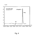
- Fig. 4 Illustrates a trace of the counts measured by PID detector for iron.
- the iron standard was prepared to provide a solution having about 100 ppb.
- an oxidizing agent e.g., hydrogen peroxide
- the graph indicates that a well-defined peak of 100 ppb iron was evidenced about 1 minute after injection.
- Fig. 5 there is illustrated a trace of the counts measured by PID detector for cadmium.
- the cadmium standard was prepared to provide a solution having about 100 ppb.
- the trace indicates that a well-defined peak of 100 ppb cadmium was evidenced a little over 1 minute after injection.
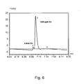
- Fig. 6 illustrates a trace of the counts measured by PID detector for tin.
- the tin standard was prepared to provide a solution having about 100 ppb.
- the trace indicates that a well-defined peak of 100 ppb tin after a small peak of trace arsenic was evidenced after injection.
- Figs. 7A and 7B illustrate traces of the counts measured by PID detector for arsenic with and without nitrogen purging of the system for low ppb levels of arsenic.
- the samples were eluted through a packed column to remove the water in order to test the need for nitrogen purging the system of oxygen for low ppb level arsenic measurements.
- Fig. 7A represents no nitrogen purging.
- Fig. 7B represents nitrogen purging for 2-3 minutes.
- arsine (AsH 3 ) is a non-retained compound by the packed column along with oxygen (which quenches the PID response)
- Figs. 7A and 7B show the effect on low ppb level of arsenic.
- arsenic is completely masked. With nitrogen purging, the arsenic peak appears.
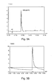
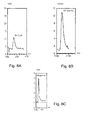
- Figs. 8A, 8B and 8C illustrate traces of the counts measured by PID detector for arsenic showing the sensitivity of PID to measure low levels of arsenic.
- Fig. 8A illustrates a trace for an aqueous sample containing 1 ppb of arsenic.
- Fig. 8B illustrates a trace for an aqueous sample containing 10 ppb of arsenic.
- Fig. 8C illustrates a trace for an aqueous sample containing 100 ppb of arsenic.
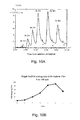
- Fig. 9 illustrates a plot/graph of the counts measured by PID for 1 ppb and 10 ppb of arsenic.
- the graph indicates that it is a linear correlation of the measured counts and, thus, a reliable method for determining low ppb levels of arsenic.
- Figs. 10A and 10B illustrate a trace and a graph, respectively, of the counts measured by PID of an aqueous sample containing 10 ppb arsenic in water.
- the sample was purged for 2-3 minutes with nitrogen and then the reducing agent (sodium borohydride) was added and the nitrogen purge was stopped while stirring was continued.
- a 1 cc gas sample was injected every minute.
- Fig. 10A the maximum value occurs between 4-6 minutes so multiple injections can be made.
- Fig. 10B is a plot/graph of the peak height values.
- the level of arsenic that is necessary to measure as published by the EPA is 10 ppm in drinking water and 10 ppb in apple juice (by the FDA). Thus, a 1ppb measurement is necessary for any analytical method for detection of arsenic.
- Fig. 11 illustrates a graph comparing the results using arsenic as the species of interest showing the effect the type of column has on the PID response.
- the x-axis is the actual ppb of arsenic in the measured sample and the y-axis is the PID measured ppb of arsenic. It is apparent from the test data that the capillary column provides the best results at low ppb levels. When no column was incorporated in the test and no nitrogen purge, the signal was lowered by greater than ten percent (10%). It is noteworthy that at the 1 ppb level where nitrogen purging was used to remove oxygen, the value obtained was 0.35 ppb instead of the expected 1 ppb. This was caused by water vapor and represents a reduction in sensitivity of greater than 80%.
- arsine (AsH 3 ) is an unretained compound and elutes very close to the air peak indicating that nitrogen purging for several minutes to remove oxygen is required to prevent quenching of the signal.
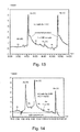
- Fig. 12 illustrates a trace showing the PID response for a 10 ppb As aqueous sample using a capillary column. As evidenced by the trace, the signal peak is sharp and pronounced.
- Figs. 13-15 illustrate traces showing the effect of incorporating an oxidizing agent in an aqueous sample of low level arsenic.
- a 9.2 ppb aqueous arsenic sample in 0.6M HCl was prepared.
- One (1) cc of sodium borohydride reducing agent was added to the sample to start the reduction. This is typical hydride generation procedure known to the skilled artisan.
- a concentrator/trap was used. Specifically, the concentrator/trap used was third column 24 containing activated charcoal. After collection, the 6" (15.24 cm) trap (i.e. third column 24) was heated to 150°C for about 1 to about 2 minutes and the sample was injected through a 10 port valve to remove the AsH 3 and conduct it to the detection system.
- Fig. 13 illustrates a trace of the arsenic sample after being desorbed from the trap. As seen in the trace, at 1 minute after injection, a small peak of As(III) and a large peak of As(V) was obtained. The As(V) peak has a broad area after the peak, which is believed to be unreacted product. It is noted that this is not seen at higher levels due to kinetics, which slow considerably at low concentrations.
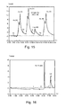
- Fig. 14 illustrates a trace of the arsenic sample where an oxidizing agent was added to the aqueous sample.
- the oxidizing agent was hydrogen peroxide (H 2 O 2 ).
- H 2 O 2 hydrogen peroxide
- A1 ml of 3% H 2 O 2 has added to the aqueous sample to convert As(III) to As(V) and to promote the reaction of the unreacted product As(V) seen in Fig. 13 .
- a comparison to Fig. 13 shows that the As(V) peak in Fig. 14 does not have the long tail observed in Fig. 13 and peak height (PH) and peak area (PA) have increased by greater than 30 percent (30%).
- the conventional method of treatment is opposite, which uses potassium iodide (KI) to reduce As(V) to As(III). This is illustrated in Fig. 15 .
- Fig. 15 there is illustrated a trace of the conventional method of treatment that uses potassium iodide (KI) to reduce As(V) to As(III).
- KI potassium iodide
- 1 cc of 2% KI is added to the aqueous sample.
- the peak for As(III) is enhanced but there is still As(V) being eluted. This continues to occur even after 14 minutes.
- Fig. 16 illustrates the effectiveness of the present invention for the detection of multiple species in an aqueous sample.
- a sample was prepared that included 15 ppb As (arsenic) and 60 ppb Cd (cadmium).
- the sample was prepared by mixing 10 cc of Cd, 5 cc of As plus 5 cc of deionized water.
- a nitrogen purge was used per the method of the present invention before adding the reducing agent NaBH 4 .
- the PID flow was 20 cc per minute.
- the arsenic peak and the cadmium peak are relatively sharp and the signals are clearly separated showing that multiple metals are detectable using the method of the present invention
- the advantages of the present invention include (1) continuous nitrogen purging is not required, but could still be used (2) a cold trap to remove water is not required when a precolumn is used, (3) a liquid nitrogen trap/concentrator for collecting the metal hydride is not required, (4) a nitrogen purge is used for a short period of time to remove oxygen to prevent signal quenching, (5) only a 1 cc gas sample of the headspace is required to obtain usable results, and (6) using PID to measure multiple species is more cost effective than any other conventional method.
- air and MH x are gases with a relatively short retention time (0.23 minutes) while water has a relative retention time of ten (10) minutes or forty (40) times longer than air and MH 3 .
- Even ethylene has a retention time four (4) times longer than air so with a short injection time even ethylene would not get through to the analytical column.
- ppb levels of MH 3 from a hydride generator is retained in a six inch (6") (15.24 cm) charcoal column and illustrated in Fig. 1 as a third column 24.
- the process involves passing the gas sample through the precolumn 22, the optional oxygen retaining column 20 for the same reasons as previously discussed before venting the nitrogen containing MH x into the charcoal column for about five to about 10 minutes to collect all of the MH 3 .
- the charcoal column 24 is heated to 150°C for about 1 to about 2 minutes to drive the metal out of the charcoal column and into an inlet port of the 10-port valve and then onto the detector system 10. It was found that, for AsH 3 , it could take 10 minutes or more to deplete the AsH 3 from the solution. This means a many fold increase in the sample for the GC/PID.
- a sparging vessel is replaced with a VOA vial.
- the VOA vial is a 40 ml VOA vial with a cover and a septum typically made of a polytetrafluoroethylene (PTFE) such as the material sold under the trademark Teflon®.
- PTFE polytetrafluoroethylene
- the VOA vial is used to avoid any air in the headspace. This is accomplished by adding 1 ml of concentrated hydrochloric acid (HCl) and a PTFE stirring bar to the vial. The vial is then filled to the brim with sample. The septum and the cover are then attached to the vial.
- a syringe is used to penetrate the septum and about 10 ml of the liquid in the vial is removed. The remaining liquid is stirred for several minutes to mix the sample and HCl before adding 1 ml of a reducing agent such as 4% sodium borahydride (NaBH 4 ) solution. The sample solution with the reducing agent is stirred for another 5-10 minutes. A 1 ml sample is removed and injected into the GC/PID.
- a reducing agent such as 4% sodium borahydride (NaBH 4 ) solution.
- NaBH 4 sodium borahydride
- the PID method for mercury is made more sensitive and specific using a pre-concentration process.
- the mercury sample that contains the mercury salt is added to the vessel 12 along with the sodium borohydride (NaBH 4 ).
- NaBH 4 sodium borohydride
- mercury is released as free mercury in gas form.
- the gas sample containing the mercury is then passed by a gold film. Any mercury in the gas sample reacts with the gold at room temperature to form a Au/Hg amalgam. Water and other organics that were no removed previously are now removed by purging with N 2 gas for several minutes. After purging, the gold film containing the Au/Hg amalgam is heated rapidly (i.e. about 25-30 seconds) to 500°C to decompose the amalgam and free the Hg, which is detected by the PID.
- the technique of using third column 24 can also be used for detecting Hg in air. Because the Hg is already in a gaseous state, the air is directly passed by a gold film. With enough sample, this method can detect 10 ppt (parts per trillion) of Hg specifically. The process involves passing about 40-50 liters of air through a gold film with N 2 gas for several minutes to remove water and other. The gold film is then subjected to flash heating (i.e. about 25-30 seconds) up to 500°C to decompose the amalgam and free the Hg, which is detected by the PID.
- flash heating i.e. about 25-30 seconds
- the concentrator 100 includes a quartz assembly 110, a mercury concentrator element 120 and a heater 130.
- Quartz assembly 110 includes a tubular quartz body 111 that defines an internal volume 111a.
- a gas inlet 112 is connected to a first body end 111b and a gas outlet is transversely to quartz body 111.
- a substantial first element portion 120a of mercury concentrator element 120 is disposed within quartz body 111. Either a gas sample or a purging gas flows through gas inlet 112, into internal volume 111a and around first element portion 120a before exiting out gas outlet 114.
- Figs. 19 and 20 there is illustrated the mercury concentrator assembly100 that includes quartz assembly 110 and mercury concentrator element 120.
- Quartz assembly 110 has tubular quartz body 111, gas inlet 112, gas outlet 114, and heater end 116.
- Mercury concentrator element 120 includes an element core 122 in the shape of a rod, a gold layer/coating 124 over element core 122.
- Concentrator element also has first element portion 120a and a second element portion 120b.
- Element core 122 is typically made of stainless steel.
- First element portion 120a is that portion of concentrator element 120 that is disposed within internal volume 111a.
- Second element portion 120b is that portion that is disposed within heater end 116 and includes an end element portion 121 that extends out of quartz body 111 through heater end 116.
- Heater end 116 is sealed around concentrator element 120.
- a gold film 124 is coated/deposited over at least first element portion 120a. It is the gold film 124 that reacts with the mercury gas to form an amalgam. It is understood that gold film 124 may be deposited over the entire surface of element core 122.
- the quartz body 111 is about 4.5 inches (about 11.4 cm) long.
- the gas inlet 112 and the gas outlet 114 are 1 ⁇ 4" (0.635 cm) diameter and the heater end 116 is about 0.5" (1.27 cm) diameter.
- First element portion 120a is about 3.5" (8.9 cm) long.
- the element core 122 is made of 304 stainless steel, polished and then plated with gold.
- the heater 130 is attached to heater end 116 using a stainless steel reducing adapter and the ferrule used in the fitting is made of graphite.
- the heater 130 is a 300 watt heater, which incorporates a thermocouple.
- the heater operates using 115 VAC and is capable of heating to 500°C in about 30 seconds. It is understood that the dimensions may be modified to accomplish the desired result and the above described dimensions are not to be construed as limiting.
Landscapes
- Chemical & Material Sciences (AREA)
- Health & Medical Sciences (AREA)
- Life Sciences & Earth Sciences (AREA)
- Physics & Mathematics (AREA)
- General Physics & Mathematics (AREA)
- Immunology (AREA)
- Pathology (AREA)
- Analytical Chemistry (AREA)
- Biochemistry (AREA)
- General Health & Medical Sciences (AREA)
- Engineering & Computer Science (AREA)
- Combustion & Propulsion (AREA)
- Food Science & Technology (AREA)
- Medicinal Chemistry (AREA)
- Chemical Kinetics & Catalysis (AREA)
- Toxicology (AREA)
- Electrochemistry (AREA)
- Investigating Or Analyzing Non-Biological Materials By The Use Of Chemical Means (AREA)
- Other Investigation Or Analysis Of Materials By Electrical Means (AREA)
- Spectroscopy & Molecular Physics (AREA)
Applications Claiming Priority (2)
| Application Number | Priority Date | Filing Date | Title |
|---|---|---|---|
| US201461975903P | 2014-04-06 | 2014-04-06 | |
| US14/672,132 US9423386B2 (en) | 2014-04-06 | 2015-03-28 | Method for ion detection |
Publications (3)
| Publication Number | Publication Date |
|---|---|
| EP2927680A2 true EP2927680A2 (de) | 2015-10-07 |
| EP2927680A3 EP2927680A3 (de) | 2016-01-06 |
| EP2927680B1 EP2927680B1 (de) | 2019-06-05 |
Family
ID=52991410
Family Applications (1)
| Application Number | Title | Priority Date | Filing Date |
|---|---|---|---|
| EP15000961.1A Active EP2927680B1 (de) | 2014-04-06 | 2015-04-02 | Verfahren zur ionendetektion |
Country Status (5)
| Country | Link |
|---|---|
| US (2) | US9423386B2 (de) |
| EP (1) | EP2927680B1 (de) |
| JP (2) | JP6608606B2 (de) |
| KR (1) | KR20150115684A (de) |
| CA (2) | CA3118232A1 (de) |
Cited By (2)
| Publication number | Priority date | Publication date | Assignee | Title |
|---|---|---|---|---|
| CN108152334A (zh) * | 2017-11-17 | 2018-06-12 | 海南核电有限公司 | 一种移动式阴阳离子分析装置 |
| US11927572B2 (en) | 2018-12-05 | 2024-03-12 | Chengdu Colin Analysis Technology Co., Ltd. | Water removal method for gas concentration sampling, sampling method and device therefor |
Families Citing this family (5)
| Publication number | Priority date | Publication date | Assignee | Title |
|---|---|---|---|---|
| JP6489379B2 (ja) * | 2015-11-02 | 2019-03-27 | 住友金属鉱山株式会社 | 重金属元素の定量方法および分離方法 |
| CN105606721B (zh) * | 2015-12-11 | 2017-10-31 | 济南市环境保护科学研究院 | 一种pm2.5中砷的分离测定方法 |
| JP7385589B2 (ja) * | 2018-03-27 | 2023-11-22 | イリノイ トゥール ワークス インコーポレイティド | 自動化された試料採取を用いた磁気ウェットベンチ |
| CN108375640B (zh) * | 2018-05-03 | 2021-05-25 | 北京农业质量标准与检测技术研究中心 | 一种基于管式炉提取菌菇中重金属铬形态的方法 |
| CN112710756A (zh) * | 2020-12-23 | 2021-04-27 | 广东省科学院生态环境与土壤研究所 | 液相色谱-原子荧光光谱联用测定三价锑和五价锑含量的方法 |
Family Cites Families (15)
| Publication number | Priority date | Publication date | Assignee | Title |
|---|---|---|---|---|
| US3859807A (en) * | 1947-08-26 | 1975-01-14 | Atomic Energy Commission | Cold trap system for recovering condensable gas from a vessel to be evacuated |
| US3693323A (en) * | 1970-12-30 | 1972-09-26 | Continental Oil Co | Process for the trapping of mercury vapors and apparatus therefor |
| US4013913A (en) | 1976-01-19 | 1977-03-22 | Hnu Systems Inc. | Ion detection electrode arrangement |
| US4413185A (en) | 1981-04-29 | 1983-11-01 | Her Majesty The Queen In Right Of Canada, As Represented By The Minister Of National Defence | Selective photoionization gas chromatograph detector |
| US5597535A (en) * | 1994-02-25 | 1997-01-28 | Tekran Inc. | Apparatus for detecting mercury |
| US5750992A (en) * | 1996-09-18 | 1998-05-12 | Tennessee Valley Authority | Method to compensate for interferences to mercury measurement in gases |
| US6461411B1 (en) | 2000-12-04 | 2002-10-08 | Matheson Tri-Gas | Method and materials for purifying hydride gases, inert gases, and non-reactive gases |
| WO2003026799A1 (en) * | 2001-09-24 | 2003-04-03 | The Johns Hopkins University | Removal of elemental mercury by photoionization |
| JP4118745B2 (ja) * | 2003-05-30 | 2008-07-16 | 大陽日酸株式会社 | 濃縮分析装置及び方法 |
| JP2006010415A (ja) * | 2004-06-23 | 2006-01-12 | Horiba Ltd | 気液分離容器、及びicp発光分析装置 |
| US7454952B2 (en) * | 2005-05-02 | 2008-11-25 | Thermo Fisher Scientific Inc. | Method and apparatus for monitoring mercury in a gas sample |
| US7507273B1 (en) * | 2005-06-20 | 2009-03-24 | 6Solutions, Llc | Chromatographic rectification of ethanol |
| US20090111189A1 (en) * | 2007-10-26 | 2009-04-30 | Alberta Research Council Inc. | Organic and inorganic mercury detection |
| JP5210854B2 (ja) * | 2008-12-24 | 2013-06-12 | 日本インスツルメンツ株式会社 | 水銀分析装置および水銀分析方法 |
| US9075016B2 (en) * | 2009-12-31 | 2015-07-07 | Emilcott Associates, Inc. | Automated control of analytical sampling with environmental monitoring system |
-
2015
- 2015-03-28 US US14/672,132 patent/US9423386B2/en active Active
- 2015-04-02 CA CA3118232A patent/CA3118232A1/en not_active Abandoned
- 2015-04-02 CA CA2886824A patent/CA2886824C/en active Active
- 2015-04-02 EP EP15000961.1A patent/EP2927680B1/de active Active
- 2015-04-06 KR KR1020150048284A patent/KR20150115684A/ko not_active Abandoned
- 2015-04-06 JP JP2015077876A patent/JP6608606B2/ja not_active Expired - Fee Related
-
2016
- 2016-07-19 US US15/213,485 patent/US9857340B2/en not_active Expired - Fee Related
-
2019
- 2019-10-24 JP JP2019193412A patent/JP6918072B2/ja not_active Expired - Fee Related
Non-Patent Citations (1)
| Title |
|---|
| None |
Cited By (2)
| Publication number | Priority date | Publication date | Assignee | Title |
|---|---|---|---|---|
| CN108152334A (zh) * | 2017-11-17 | 2018-06-12 | 海南核电有限公司 | 一种移动式阴阳离子分析装置 |
| US11927572B2 (en) | 2018-12-05 | 2024-03-12 | Chengdu Colin Analysis Technology Co., Ltd. | Water removal method for gas concentration sampling, sampling method and device therefor |
Also Published As
| Publication number | Publication date |
|---|---|
| EP2927680A3 (de) | 2016-01-06 |
| US20150301008A1 (en) | 2015-10-22 |
| KR20150115684A (ko) | 2015-10-14 |
| US20160327526A1 (en) | 2016-11-10 |
| US9423386B2 (en) | 2016-08-23 |
| JP6608606B2 (ja) | 2019-11-20 |
| EP2927680B1 (de) | 2019-06-05 |
| US9857340B2 (en) | 2018-01-02 |
| CA2886824C (en) | 2021-07-06 |
| CA3118232A1 (en) | 2015-10-06 |
| JP6918072B2 (ja) | 2021-08-11 |
| JP2020024215A (ja) | 2020-02-13 |
| CA2886824A1 (en) | 2015-10-06 |
| JP2015200653A (ja) | 2015-11-12 |
Similar Documents
| Publication | Publication Date | Title |
|---|---|---|
| US9857340B2 (en) | Method for ion detection | |
| Long et al. | Recent advance of hydride generation–analytical atomic spectrometry: part I—technique development | |
| Zhang et al. | Application of flow injection–green chemical vapor generation–atomic fluorescence spectrometry to ultrasensitive mercury speciation analysis of water and biological samples | |
| Li et al. | Determination of Hg2+ by on-line separation and pre-concentration with atmospheric-pressure solution-cathode glow discharge atomic emission spectrometry | |
| US4851683A (en) | Element specific radio frequency discharge helium plasma detector for chromatography | |
| Sanz-Medel | Flow analysis with atomic spectrometric detectors | |
| Gao et al. | On-line preconcentration and in situ photochemical vapor generation in coiled reactor for speciation analysis of mercury and methylmercury by atomic fluorescence spectrometry | |
| de Torres et al. | Automated on-line separation–preconcentration system for inductively coupled plasma atomic emission spectrometry and its application to mercury determination | |
| Gil et al. | Optimization of a single-drop microextraction method for multielemental determination by electrothermal vaporization inductively coupled plasma mass spectrometry following in situ vapor generation | |
| Said‐Ahmad et al. | A sensitive method for the sulfur isotope analysis of dimethyl sulfide and dimethylsulfoniopropionate in seawater | |
| Valdivia et al. | Determination of As, Sb and Hg in water samples by flow injection coupled HR CS ETAAS with an in situ hydride generator | |
| Guerrero et al. | High resolution continuum source atomic absorption spectrometry and solid phase extraction for the simultaneous separation/preconcentration and sequential monitoring of Sb, Bi, Sn and Hg in low concentrations | |
| Wang et al. | Microplasma-based excitation/ionization source: from atomic to mass spectrometry | |
| Van Loon et al. | Inductively coupled, plasma source mass spectrometry-a new element/isotope specific mass spectrometry detector for chromatography | |
| Chiba et al. | Determination of halogenated organic compounds in water by gas chromatography/atmospheric pressure helium microwave-induced plasma emission spectrometry with a heated discharge tube for pyrolysis | |
| Stanisz et al. | Solid-phase extraction with multiwalled carbon nanotubes prior to photochemical generation of cadmium coupled to high-resolution continuum source atomic absorption spectrometry | |
| Feldmann et al. | Cryotrapping of CO2-rich atmospheres for the analysis of volatile metal compounds using capillary GC-ICP-MSPresented at the 2001 European Winter Conference on Plasma Spectrochemistry, Lillehammer, Norway, February 4–8, 2001. | |
| JP3626683B2 (ja) | 酸化物表面皮膜を有する輸送型検出器 | |
| Evans et al. | Atomic spectrometry update. Advances in atomic spectrometry and related techniques | |
| Yang et al. | A portable chemical vapor generation purge-and-trap point discharge optical emission spectrometer for field selective analysis of Se (Ⅳ) in water | |
| Krenželok et al. | The Use of a Membrane GasLiquid Separator for Flow Injection Hydride Generation Atomic Absorption Spectrometry On-Line Speciation and Determination of As (III) and As (V) | |
| Welz | Atomic absorption spectrometry | |
| Iqbal et al. | On-line determination of trace copper in water using near-infrared spectroscopy and fluidized bed enrichment | |
| Wolska et al. | Influence of concentration and sample volume on the recovery of compounds from water following direct sorption on Tenax TA–thermal desorption | |
| Zlatkis et al. | Concentration of volatile organics in aqueous solutions on uncoated capillary columns and their thermal desorption |
Legal Events
| Date | Code | Title | Description |
|---|---|---|---|
| PUAI | Public reference made under article 153(3) epc to a published international application that has entered the european phase |
Free format text: ORIGINAL CODE: 0009012 |
|
| AK | Designated contracting states |
Kind code of ref document: A2 Designated state(s): AL AT BE BG CH CY CZ DE DK EE ES FI FR GB GR HR HU IE IS IT LI LT LU LV MC MK MT NL NO PL PT RO RS SE SI SK SM TR |
|
| AX | Request for extension of the european patent |
Extension state: BA ME |
|
| PUAL | Search report despatched |
Free format text: ORIGINAL CODE: 0009013 |
|
| AK | Designated contracting states |
Kind code of ref document: A3 Designated state(s): AL AT BE BG CH CY CZ DE DK EE ES FI FR GB GR HR HU IE IS IT LI LT LU LV MC MK MT NL NO PL PT RO RS SE SI SK SM TR |
|
| AX | Request for extension of the european patent |
Extension state: BA ME |
|
| RIC1 | Information provided on ipc code assigned before grant |
Ipc: G01N 30/88 20060101ALI20151127BHEP Ipc: G01N 30/64 20060101ALN20151127BHEP Ipc: G01N 30/00 20060101ALN20151127BHEP Ipc: G01N 33/00 20060101ALI20151127BHEP Ipc: G01N 30/08 20060101ALN20151127BHEP Ipc: G01N 30/14 20060101ALN20151127BHEP Ipc: G01N 30/06 20060101AFI20151127BHEP Ipc: G01N 30/96 20060101ALN20151127BHEP |
|
| 17P | Request for examination filed |
Effective date: 20160706 |
|
| RBV | Designated contracting states (corrected) |
Designated state(s): AL AT BE BG CH CY CZ DE DK EE ES FI FR GB GR HR HU IE IS IT LI LT LU LV MC MK MT NL NO PL PT RO RS SE SI SK SM TR |
|
| STAA | Information on the status of an ep patent application or granted ep patent |
Free format text: STATUS: EXAMINATION IS IN PROGRESS |
|
| 17Q | First examination report despatched |
Effective date: 20180102 |
|
| RIC1 | Information provided on ipc code assigned before grant |
Ipc: G01N 30/88 20060101ALI20181031BHEP Ipc: G01N 30/06 20060101AFI20181031BHEP Ipc: G01N 30/00 20060101ALN20181031BHEP Ipc: G01N 30/14 20060101ALN20181031BHEP Ipc: G01N 33/00 20060101ALI20181031BHEP Ipc: G01N 30/08 20060101ALN20181031BHEP Ipc: G01N 30/96 20060101ALN20181031BHEP Ipc: G01N 30/64 20060101ALN20181031BHEP |
|
| GRAP | Despatch of communication of intention to grant a patent |
Free format text: ORIGINAL CODE: EPIDOSNIGR1 |
|
| STAA | Information on the status of an ep patent application or granted ep patent |
Free format text: STATUS: GRANT OF PATENT IS INTENDED |
|
| INTG | Intention to grant announced |
Effective date: 20181207 |
|
| GRAS | Grant fee paid |
Free format text: ORIGINAL CODE: EPIDOSNIGR3 |
|
| GRAA | (expected) grant |
Free format text: ORIGINAL CODE: 0009210 |
|
| STAA | Information on the status of an ep patent application or granted ep patent |
Free format text: STATUS: THE PATENT HAS BEEN GRANTED |
|
| AK | Designated contracting states |
Kind code of ref document: B1 Designated state(s): AL AT BE BG CH CY CZ DE DK EE ES FI FR GB GR HR HU IE IS IT LI LT LU LV MC MK MT NL NO PL PT RO RS SE SI SK SM TR |
|
| REG | Reference to a national code |
Ref country code: GB Ref legal event code: FG4D |
|
| REG | Reference to a national code |
Ref country code: CH Ref legal event code: EP |
|
| REG | Reference to a national code |
Ref country code: AT Ref legal event code: REF Ref document number: 1140528 Country of ref document: AT Kind code of ref document: T Effective date: 20190615 |
|
| REG | Reference to a national code |
Ref country code: IE Ref legal event code: FG4D |
|
| REG | Reference to a national code |
Ref country code: DE Ref legal event code: R096 Ref document number: 602015031242 Country of ref document: DE |
|
| REG | Reference to a national code |
Ref country code: NL Ref legal event code: MP Effective date: 20190605 |
|
| REG | Reference to a national code |
Ref country code: LT Ref legal event code: MG4D |
|
| PG25 | Lapsed in a contracting state [announced via postgrant information from national office to epo] |
Ref country code: AL Free format text: LAPSE BECAUSE OF FAILURE TO SUBMIT A TRANSLATION OF THE DESCRIPTION OR TO PAY THE FEE WITHIN THE PRESCRIBED TIME-LIMIT Effective date: 20190605 Ref country code: ES Free format text: LAPSE BECAUSE OF FAILURE TO SUBMIT A TRANSLATION OF THE DESCRIPTION OR TO PAY THE FEE WITHIN THE PRESCRIBED TIME-LIMIT Effective date: 20190605 Ref country code: SE Free format text: LAPSE BECAUSE OF FAILURE TO SUBMIT A TRANSLATION OF THE DESCRIPTION OR TO PAY THE FEE WITHIN THE PRESCRIBED TIME-LIMIT Effective date: 20190605 Ref country code: NO Free format text: LAPSE BECAUSE OF FAILURE TO SUBMIT A TRANSLATION OF THE DESCRIPTION OR TO PAY THE FEE WITHIN THE PRESCRIBED TIME-LIMIT Effective date: 20190905 Ref country code: HR Free format text: LAPSE BECAUSE OF FAILURE TO SUBMIT A TRANSLATION OF THE DESCRIPTION OR TO PAY THE FEE WITHIN THE PRESCRIBED TIME-LIMIT Effective date: 20190605 Ref country code: FI Free format text: LAPSE BECAUSE OF FAILURE TO SUBMIT A TRANSLATION OF THE DESCRIPTION OR TO PAY THE FEE WITHIN THE PRESCRIBED TIME-LIMIT Effective date: 20190605 Ref country code: LT Free format text: LAPSE BECAUSE OF FAILURE TO SUBMIT A TRANSLATION OF THE DESCRIPTION OR TO PAY THE FEE WITHIN THE PRESCRIBED TIME-LIMIT Effective date: 20190605 |
|
| PG25 | Lapsed in a contracting state [announced via postgrant information from national office to epo] |
Ref country code: LV Free format text: LAPSE BECAUSE OF FAILURE TO SUBMIT A TRANSLATION OF THE DESCRIPTION OR TO PAY THE FEE WITHIN THE PRESCRIBED TIME-LIMIT Effective date: 20190605 Ref country code: RS Free format text: LAPSE BECAUSE OF FAILURE TO SUBMIT A TRANSLATION OF THE DESCRIPTION OR TO PAY THE FEE WITHIN THE PRESCRIBED TIME-LIMIT Effective date: 20190605 Ref country code: BG Free format text: LAPSE BECAUSE OF FAILURE TO SUBMIT A TRANSLATION OF THE DESCRIPTION OR TO PAY THE FEE WITHIN THE PRESCRIBED TIME-LIMIT Effective date: 20190905 Ref country code: GR Free format text: LAPSE BECAUSE OF FAILURE TO SUBMIT A TRANSLATION OF THE DESCRIPTION OR TO PAY THE FEE WITHIN THE PRESCRIBED TIME-LIMIT Effective date: 20190906 |
|
| REG | Reference to a national code |
Ref country code: AT Ref legal event code: MK05 Ref document number: 1140528 Country of ref document: AT Kind code of ref document: T Effective date: 20190605 |
|
| PG25 | Lapsed in a contracting state [announced via postgrant information from national office to epo] |
Ref country code: PT Free format text: LAPSE BECAUSE OF FAILURE TO SUBMIT A TRANSLATION OF THE DESCRIPTION OR TO PAY THE FEE WITHIN THE PRESCRIBED TIME-LIMIT Effective date: 20191007 Ref country code: SK Free format text: LAPSE BECAUSE OF FAILURE TO SUBMIT A TRANSLATION OF THE DESCRIPTION OR TO PAY THE FEE WITHIN THE PRESCRIBED TIME-LIMIT Effective date: 20190605 Ref country code: AT Free format text: LAPSE BECAUSE OF FAILURE TO SUBMIT A TRANSLATION OF THE DESCRIPTION OR TO PAY THE FEE WITHIN THE PRESCRIBED TIME-LIMIT Effective date: 20190605 Ref country code: EE Free format text: LAPSE BECAUSE OF FAILURE TO SUBMIT A TRANSLATION OF THE DESCRIPTION OR TO PAY THE FEE WITHIN THE PRESCRIBED TIME-LIMIT Effective date: 20190605 Ref country code: NL Free format text: LAPSE BECAUSE OF FAILURE TO SUBMIT A TRANSLATION OF THE DESCRIPTION OR TO PAY THE FEE WITHIN THE PRESCRIBED TIME-LIMIT Effective date: 20190605 Ref country code: RO Free format text: LAPSE BECAUSE OF FAILURE TO SUBMIT A TRANSLATION OF THE DESCRIPTION OR TO PAY THE FEE WITHIN THE PRESCRIBED TIME-LIMIT Effective date: 20190605 Ref country code: CZ Free format text: LAPSE BECAUSE OF FAILURE TO SUBMIT A TRANSLATION OF THE DESCRIPTION OR TO PAY THE FEE WITHIN THE PRESCRIBED TIME-LIMIT Effective date: 20190605 |
|
| PG25 | Lapsed in a contracting state [announced via postgrant information from national office to epo] |
Ref country code: SM Free format text: LAPSE BECAUSE OF FAILURE TO SUBMIT A TRANSLATION OF THE DESCRIPTION OR TO PAY THE FEE WITHIN THE PRESCRIBED TIME-LIMIT Effective date: 20190605 Ref country code: IT Free format text: LAPSE BECAUSE OF FAILURE TO SUBMIT A TRANSLATION OF THE DESCRIPTION OR TO PAY THE FEE WITHIN THE PRESCRIBED TIME-LIMIT Effective date: 20190605 Ref country code: IS Free format text: LAPSE BECAUSE OF FAILURE TO SUBMIT A TRANSLATION OF THE DESCRIPTION OR TO PAY THE FEE WITHIN THE PRESCRIBED TIME-LIMIT Effective date: 20191005 |
|
| REG | Reference to a national code |
Ref country code: DE Ref legal event code: R097 Ref document number: 602015031242 Country of ref document: DE |
|
| PG25 | Lapsed in a contracting state [announced via postgrant information from national office to epo] |
Ref country code: TR Free format text: LAPSE BECAUSE OF FAILURE TO SUBMIT A TRANSLATION OF THE DESCRIPTION OR TO PAY THE FEE WITHIN THE PRESCRIBED TIME-LIMIT Effective date: 20190605 |
|
| PLBE | No opposition filed within time limit |
Free format text: ORIGINAL CODE: 0009261 |
|
| STAA | Information on the status of an ep patent application or granted ep patent |
Free format text: STATUS: NO OPPOSITION FILED WITHIN TIME LIMIT |
|
| PG25 | Lapsed in a contracting state [announced via postgrant information from national office to epo] |
Ref country code: PL Free format text: LAPSE BECAUSE OF FAILURE TO SUBMIT A TRANSLATION OF THE DESCRIPTION OR TO PAY THE FEE WITHIN THE PRESCRIBED TIME-LIMIT Effective date: 20190605 Ref country code: DK Free format text: LAPSE BECAUSE OF FAILURE TO SUBMIT A TRANSLATION OF THE DESCRIPTION OR TO PAY THE FEE WITHIN THE PRESCRIBED TIME-LIMIT Effective date: 20190605 |
|
| 26N | No opposition filed |
Effective date: 20200306 |
|
| PG25 | Lapsed in a contracting state [announced via postgrant information from national office to epo] |
Ref country code: SI Free format text: LAPSE BECAUSE OF FAILURE TO SUBMIT A TRANSLATION OF THE DESCRIPTION OR TO PAY THE FEE WITHIN THE PRESCRIBED TIME-LIMIT Effective date: 20190605 |
|
| PG25 | Lapsed in a contracting state [announced via postgrant information from national office to epo] |
Ref country code: MC Free format text: LAPSE BECAUSE OF FAILURE TO SUBMIT A TRANSLATION OF THE DESCRIPTION OR TO PAY THE FEE WITHIN THE PRESCRIBED TIME-LIMIT Effective date: 20190605 |
|
| REG | Reference to a national code |
Ref country code: CH Ref legal event code: PL |
|
| PG25 | Lapsed in a contracting state [announced via postgrant information from national office to epo] |
Ref country code: CH Free format text: LAPSE BECAUSE OF NON-PAYMENT OF DUE FEES Effective date: 20200430 Ref country code: LI Free format text: LAPSE BECAUSE OF NON-PAYMENT OF DUE FEES Effective date: 20200430 Ref country code: LU Free format text: LAPSE BECAUSE OF NON-PAYMENT OF DUE FEES Effective date: 20200402 |
|
| REG | Reference to a national code |
Ref country code: BE Ref legal event code: MM Effective date: 20200430 |
|
| PG25 | Lapsed in a contracting state [announced via postgrant information from national office to epo] |
Ref country code: BE Free format text: LAPSE BECAUSE OF NON-PAYMENT OF DUE FEES Effective date: 20200430 |
|
| PG25 | Lapsed in a contracting state [announced via postgrant information from national office to epo] |
Ref country code: IE Free format text: LAPSE BECAUSE OF NON-PAYMENT OF DUE FEES Effective date: 20200402 |
|
| PG25 | Lapsed in a contracting state [announced via postgrant information from national office to epo] |
Ref country code: MT Free format text: LAPSE BECAUSE OF FAILURE TO SUBMIT A TRANSLATION OF THE DESCRIPTION OR TO PAY THE FEE WITHIN THE PRESCRIBED TIME-LIMIT Effective date: 20190605 Ref country code: CY Free format text: LAPSE BECAUSE OF FAILURE TO SUBMIT A TRANSLATION OF THE DESCRIPTION OR TO PAY THE FEE WITHIN THE PRESCRIBED TIME-LIMIT Effective date: 20190605 |
|
| PG25 | Lapsed in a contracting state [announced via postgrant information from national office to epo] |
Ref country code: MK Free format text: LAPSE BECAUSE OF FAILURE TO SUBMIT A TRANSLATION OF THE DESCRIPTION OR TO PAY THE FEE WITHIN THE PRESCRIBED TIME-LIMIT Effective date: 20190605 |
|
| PGFP | Annual fee paid to national office [announced via postgrant information from national office to epo] |
Ref country code: GB Payment date: 20220915 Year of fee payment: 8 Ref country code: DE Payment date: 20220928 Year of fee payment: 8 |
|
| PGFP | Annual fee paid to national office [announced via postgrant information from national office to epo] |
Ref country code: FR Payment date: 20220915 Year of fee payment: 8 |
|
| REG | Reference to a national code |
Ref country code: DE Ref legal event code: R119 Ref document number: 602015031242 Country of ref document: DE |
|
| GBPC | Gb: european patent ceased through non-payment of renewal fee |
Effective date: 20230402 |
|
| PG25 | Lapsed in a contracting state [announced via postgrant information from national office to epo] |
Ref country code: GB Free format text: LAPSE BECAUSE OF NON-PAYMENT OF DUE FEES Effective date: 20230402 |
|
| PG25 | Lapsed in a contracting state [announced via postgrant information from national office to epo] |
Ref country code: GB Free format text: LAPSE BECAUSE OF NON-PAYMENT OF DUE FEES Effective date: 20230402 Ref country code: FR Free format text: LAPSE BECAUSE OF NON-PAYMENT OF DUE FEES Effective date: 20230430 Ref country code: DE Free format text: LAPSE BECAUSE OF NON-PAYMENT OF DUE FEES Effective date: 20231103 |