EP2927697A1 - Analyseur d'échantillon et récipient de réactif - Google Patents
Analyseur d'échantillon et récipient de réactif Download PDFInfo
- Publication number
- EP2927697A1 EP2927697A1 EP15159910.7A EP15159910A EP2927697A1 EP 2927697 A1 EP2927697 A1 EP 2927697A1 EP 15159910 A EP15159910 A EP 15159910A EP 2927697 A1 EP2927697 A1 EP 2927697A1
- Authority
- EP
- European Patent Office
- Prior art keywords
- reagent container
- reagent
- aspirating tube
- container
- sample analyzer
- Prior art date
- Legal status (The legal status is an assumption and is not a legal conclusion. Google has not performed a legal analysis and makes no representation as to the accuracy of the status listed.)
- Granted
Links
- 0 CCC(CCC(F)(F)F)CC(CCC(CC(CC)CC(C)*C)(**)C(C1C)=C1C12)C1C2=* Chemical compound CCC(CCC(F)(F)F)CC(CCC(CC(CC)CC(C)*C)(**)C(C1C)=C1C12)C1C2=* 0.000 description 1
Images










Classifications
-
- B—PERFORMING OPERATIONS; TRANSPORTING
- B01—PHYSICAL OR CHEMICAL PROCESSES OR APPARATUS IN GENERAL
- B01L—CHEMICAL OR PHYSICAL LABORATORY APPARATUS FOR GENERAL USE
- B01L3/00—Containers or dishes for laboratory use, e.g. laboratory glassware; Droppers
- B01L3/50—Containers for the purpose of retaining a material to be analysed, e.g. test tubes
- B01L3/508—Rigid containers without fluid transport within
-
- B—PERFORMING OPERATIONS; TRANSPORTING
- B01—PHYSICAL OR CHEMICAL PROCESSES OR APPARATUS IN GENERAL
- B01L—CHEMICAL OR PHYSICAL LABORATORY APPARATUS FOR GENERAL USE
- B01L3/00—Containers or dishes for laboratory use, e.g. laboratory glassware; Droppers
- B01L3/02—Burettes; Pipettes
- B01L3/0289—Apparatus for withdrawing or distributing predetermined quantities of fluid
- B01L3/0293—Apparatus for withdrawing or distributing predetermined quantities of fluid for liquids
-
- B—PERFORMING OPERATIONS; TRANSPORTING
- B01—PHYSICAL OR CHEMICAL PROCESSES OR APPARATUS IN GENERAL
- B01L—CHEMICAL OR PHYSICAL LABORATORY APPARATUS FOR GENERAL USE
- B01L3/00—Containers or dishes for laboratory use, e.g. laboratory glassware; Droppers
- B01L3/52—Containers specially adapted for storing or dispensing a reagent
- B01L3/523—Containers specially adapted for storing or dispensing a reagent with means for closing or opening
-
- G—PHYSICS
- G01—MEASURING; TESTING
- G01N—INVESTIGATING OR ANALYSING MATERIALS BY DETERMINING THEIR CHEMICAL OR PHYSICAL PROPERTIES
- G01N35/00—Automatic analysis not limited to methods or materials provided for in any single one of groups G01N1/00 - G01N33/00; Handling materials therefor
- G01N35/10—Devices for transferring samples or any liquids to, in, or from, the analysis apparatus, e.g. suction devices, injection devices
- G01N35/1002—Reagent dispensers
-
- G—PHYSICS
- G01—MEASURING; TESTING
- G01N—INVESTIGATING OR ANALYSING MATERIALS BY DETERMINING THEIR CHEMICAL OR PHYSICAL PROPERTIES
- G01N35/00—Automatic analysis not limited to methods or materials provided for in any single one of groups G01N1/00 - G01N33/00; Handling materials therefor
- G01N35/10—Devices for transferring samples or any liquids to, in, or from, the analysis apparatus, e.g. suction devices, injection devices
- G01N35/1009—Characterised by arrangements for controlling the aspiration or dispense of liquids
- G01N35/1011—Control of the position or alignment of the transfer device
-
- B—PERFORMING OPERATIONS; TRANSPORTING
- B01—PHYSICAL OR CHEMICAL PROCESSES OR APPARATUS IN GENERAL
- B01L—CHEMICAL OR PHYSICAL LABORATORY APPARATUS FOR GENERAL USE
- B01L2200/00—Solutions for specific problems relating to chemical or physical laboratory apparatus
- B01L2200/02—Adapting objects or devices to another
- B01L2200/025—Align devices or objects to ensure defined positions relative to each other
-
- B—PERFORMING OPERATIONS; TRANSPORTING
- B01—PHYSICAL OR CHEMICAL PROCESSES OR APPARATUS IN GENERAL
- B01L—CHEMICAL OR PHYSICAL LABORATORY APPARATUS FOR GENERAL USE
- B01L2200/00—Solutions for specific problems relating to chemical or physical laboratory apparatus
- B01L2200/14—Process control and prevention of errors
- B01L2200/141—Preventing contamination, tampering
-
- B—PERFORMING OPERATIONS; TRANSPORTING
- B01—PHYSICAL OR CHEMICAL PROCESSES OR APPARATUS IN GENERAL
- B01L—CHEMICAL OR PHYSICAL LABORATORY APPARATUS FOR GENERAL USE
- B01L2200/00—Solutions for specific problems relating to chemical or physical laboratory apparatus
- B01L2200/16—Reagents, handling or storing thereof
-
- B—PERFORMING OPERATIONS; TRANSPORTING
- B01—PHYSICAL OR CHEMICAL PROCESSES OR APPARATUS IN GENERAL
- B01L—CHEMICAL OR PHYSICAL LABORATORY APPARATUS FOR GENERAL USE
- B01L2300/00—Additional constructional details
- B01L2300/04—Closures and closing means
- B01L2300/041—Connecting closures to device or container
-
- B—PERFORMING OPERATIONS; TRANSPORTING
- B01—PHYSICAL OR CHEMICAL PROCESSES OR APPARATUS IN GENERAL
- B01L—CHEMICAL OR PHYSICAL LABORATORY APPARATUS FOR GENERAL USE
- B01L2300/00—Additional constructional details
- B01L2300/08—Geometry, shape and general structure
- B01L2300/0809—Geometry, shape and general structure rectangular shaped
-
- G—PHYSICS
- G01—MEASURING; TESTING
- G01N—INVESTIGATING OR ANALYSING MATERIALS BY DETERMINING THEIR CHEMICAL OR PHYSICAL PROPERTIES
- G01N35/00—Automatic analysis not limited to methods or materials provided for in any single one of groups G01N1/00 - G01N33/00; Handling materials therefor
- G01N2035/00178—Special arrangements of analysers
- G01N2035/00277—Special precautions to avoid contamination (e.g. enclosures, glove- boxes, sealed sample carriers, disposal of contaminated material)
-
- G—PHYSICS
- G01—MEASURING; TESTING
- G01N—INVESTIGATING OR ANALYSING MATERIALS BY DETERMINING THEIR CHEMICAL OR PHYSICAL PROPERTIES
- G01N35/00—Automatic analysis not limited to methods or materials provided for in any single one of groups G01N1/00 - G01N33/00; Handling materials therefor
- G01N2035/00178—Special arrangements of analysers
- G01N2035/00306—Housings, cabinets, control panels (details)
Definitions
- the present invention relates to sample analyzers and reagent containers.
- an analyzer that includes: reagent containers each having an opening; support portions which each hold a reagent container; and aspirating tubes which each aspirate a reagent in a reagent container.
- This analyzer includes a rotation mechanism which rotates each support portion toward the inner back side of the analyzer. Moreover, the support portion on which the reagent container is set is rotated toward the inner back side of the analyzer by a user. Accordingly, the reagent container is set, in a state where the position of the aspirating tube is aligned with the position of the reagent container. In this state, the aspirating tube is allowed to enter the reagent container, and the reagent is aspirated by the aspirating tube.
- a first aspect of the present invention is a sample analyzer comprising: a reagent container setting part configured to install a reagent-container retainer for retaining a reagent container having an opening; an aspirating tube configured to aspirate a reagent in the reagent container; and an aspirating tube holder configured to hold the aspirating tube.
- the aspirating tube holder includes a cover, the cover having an open portion provided from a bottom face thereof to a side face thereof, the cover covering the aspirating tube with a region thereof other than the open portion.
- the aspirating tube holder includes a guide portion configured to guide the aspirating tube holder relative to the reagent-container retainer such that the aspirating tube holder is allowed to reach a state where the aspirating tube has entered the reagent container or a state where the aspirating tube has retreated from the reagent container.
- a second aspect of the present invention is a sample analyzer comprising: a reagent container setting part configured to install a reagent container having an opening; an aspirating tube configured to aspirate a reagent in the reagent container; and an aspirating tube holder configured to hold the aspirating tube.
- the aspirating tube holder includes a cover, the cover having an open portion provided from a bottom face thereof to a side face thereof, the cover covering the aspirating tube with a region thereof other than the open portion.
- the aspirating tube holder includes a guide portion configured to guide the aspirating tube holder relative to the reagent container such that the aspirating tube holder is allowed to reach a state where the aspirating tube has entered the reagent container or a state where the aspirating tube has retreated from the reagent container.
- a third aspect of the present invention is a reagent container for a sample analyzer, the sample analyzer comprising: an aspirating tube configured to aspirate a reagent; and an aspirating tube holder configured to hold the aspirating tube, wherein the aspirating tube holder includes a cover, the cover having an open portion provided from a bottom face thereof to a side face thereof, the cover covering the aspirating tube with a region thereof other than the open portion, the reagent container including: a reagent container body including an opening that allows the aspirating tube to enter; and a guided portion configured to allow the aspirating tube holder to be guided relative to the reagent container body such that the aspirating tube holder is allowed to reach a state where the aspirating tube has entered the reagent container body or a state where the aspirating tube has retreated from the reagent container body.
- the aspirating tube it is possible to allow the aspirating tube to enter the reagent container, with the position of the aspirating tube aligned with the position of the reagent container through simpler configuration.
- the sample analysis system 1 includes a sample analyzer 2, a first reagent container 3a to be used in performing white blood cell classification, a second reagent container 3b to be used in performing analysis of reticulocytes, a first reagent-container retainer 4a, and a second reagent-container retainer 4b.
- the sample analyzer 2 measures blood which is a sample. Specifically, the sample analyzer 2 aspirates blood from a sample container 150 to prepare a detection specimen from the aspirated blood. Then, the sample analyzer 2 performs white blood cell classification and analysis of reticulocytes of blood from the detection specimen.
- the outer shape of the body of the sample analyzer 2 is formed by a housing 2a.
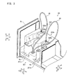
- the sample analyzer 2 includes, on the left face of the housing 2a, a drawer part 2b for putting a reagent container setting part 221 (see FIG. 3 ) into/out of the housing 2a. Accordingly, it is possible to keep the reagent container setting part 221 inside the housing 2a when no reagent container is replaced as in normal use time.
- the sample analyzer 2 also includes a display portion 2c on the front face on a Y2 direction side of the housing 2a.
- the display portion 2c has a function of displaying information such as analysis results obtained through analysis performed by the sample analysis system 1.
- the Y2 direction is the forward direction of the sample analyzer 2.
- a Y1 direction is the rearward direction of the sample analyzer 2.
- the sample analyzer 2 will be described in detail later.
- the reagent container setting part 221 includes a first reagent container setting part 221 a in which to set the first reagent container 3 a, and a second reagent container setting part 221b in which to set the second reagent container 3b.
- the first reagent container 3 a is set in the first reagent container setting part 221 a in a state of being retained in the first reagent-container retainer 4a.
- the second reagent container 3b is set in the second reagent container setting part 221b in a state of being retained in the second reagent-container retainer 4b.
- the first reagent container setting part 221 a includes a recessed portion 2211.
- the first reagent container setting part 221a is configured such that the first reagent-container retainer 4a retaining the first reagent container 3 a is fitted in the recessed portion 2211.
- the second reagent container setting part 221b includes a recessed portion not shown.
- the second reagent container setting part 221b is configured such that the second reagent-container retainer 4b retaining the second reagent container 3b is fitted in the recessed portion.
- the first reagent container setting part 221 a and the second reagent container setting part 221b will be described in detail later.
- the first reagent container 3a contains a staining liquid which stains nucleic acids of white blood cells to be used in measurement for white blood cell classification.
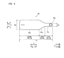
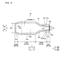
- the first reagent container 3a includes a first portion 31 a, a second portion 32a, a third portion 33a, an opening 34a, and a bottom portion 35a.
- a label 36a indicating reagent information is attached so as to cover the side face on the Y2 side.
- a part of the label 36a is blue.
- the bottom portion 35a is formed so as to be inclined such that the Y1 side of the first reagent container 3a is lower than the Y2 side thereof.
- the first portion 31a has a width W1 in an X direction.
- the second portion 32a has a width W2 greater than that of the first portion 31a.
- the third portion 33a is configured so as to connect the first portion 31a to the second portion 32a.
- the first portion 31 a and the second portion 32a are formed in parallel in a Y direction.
- the first reagent container 3a has a length L1 in the Y direction.
- the opening 34a is provided on a Z 1 side of the first portion 31 a.
- the opening 34a is provided near the end on the Y1 side of the first portion 31a.
- the Z1 direction is the upward direction of the sample analyzer 2.
- a Z2 direction is the downward direction of the sample analyzer 2.
- the second reagent container 3b contains a staining liquid which stains reticulocytes to be used in reticulocyte measurement.
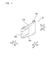
- the second reagent container 3b includes a body portion 31b and an opening 32b.
- the body portion 31b includes a bottom portion 33b inclined such that the Y1 side thereof is lower than the Y2 side thereof.
- the second reagent container 3b has a shape different from that of the first reagent container 3 a.
- a label 34b indicating reagent information is attached so as to cover the side face on the Y2 side. A part of the label 34b is red.
- the body portion 31b has, in the X direction, a width W1 which is substantially constant. That is, the body portion 31b has, in the X direction, a width that is substantially equal to the width W1 of the first portion 31a of the first reagent container 3a.
- the body portion 31b has a length L2 in the Y direction.
- the opening 32b is provided on the Z1 side of the body portion 31b.
- the opening 32b is provided near the end on the Y1 side of the body portion 31b.
- the first reagent-container retainer 4a is formed in a shape of a case having a bottom and an opening on the upper face thereof.
- the first reagent-container retainer 4a includes a first portion 41a, a second portion 42a, a third portion 43 a, and a fourth portion 44a.
- the first reagent-container retainer 4a includes a bottom portion 45a of a shape corresponding to that of the bottom portion 35a of the first reagent container 3 a.
- the first reagent-container retainer 4a includes a guided portion 46a, and claws 47a formed near the lower end of the first reagent-container retainer 4a.
- the first reagent-container retainer 4a includes a cutout 48a formed on the Z1 side of the first portion 41 a.
- the first portion 41 a is formed such that the width between its inner faces is W1 in the X direction.
- the second portion 42a is formed such that the width between its inner faces is W2 in the X direction.
- the third portion 43a is formed such that the maximum width between its inner faces is W3 in the X direction.
- the fourth portion 44a is formed so as to connect the first portion 41 a to the third portion 43a.
- the width W2 of the second portion 42a is greater than the width W1 of the first portion 41a.
- the width W3 of the third portion 43a is greater than the width W2 of the second portion 42a.
- the first portion 41a and the second portion 42a are configured so as to respectively sandwich the first portion 31a and the second portion 32a of the first reagent container 3a.
- the first reagent-container retainer 4a is formed such that, in the Y direction, the length between its inner faces is substantially the same as the length L1 of the first reagent container 3a. Accordingly, the first reagent-container retainer 4a fixes the first reagent container 3a in the X direction and the Y direction.
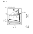
- the first reagent-container retainer 4a is configured such that the side face of the first reagent container 3a retained in the first reagent-container retainer 4a has a clearance C1 with respect to the corresponding inner face of the third portion 43a and with respect to the corresponding inner face of the fourth portion 44a of the first reagent-container retainer 4a. Accordingly, even when the sample analysis system 1 is used in a place where the atmospheric pressure is low, and the first reagent container 3a has expanded in the X direction, the clearance C1 can absorb the expanded volume.
- the first reagent container 3a retained in the first reagent-container retainer 4a is indicated by a dotted line.
- the guided portion 46a is configured to guide an aspirating tube holder 224a relative to the first reagent container 3a such that the aspirating tube holder 224a is allowed to reach a state where an aspirating tube 223a described later has entered the first reagent container 3 a or a state where the aspirating tube 223a has retreated from the first reagent container 3a.
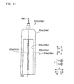
- the guided portion 46a is configured by two guided rails 461 a and two guided rails 462a.
- the guided rails 461 a are provided on the outer faces on the X1 side and the X2 side of the first portion 41 a, respectively.
- the guided rails 462a are provided on the outer faces on the X1 side and the X2 side of the fourth portion 44a, respectively.
- the guided rails 461a and 462a are each formed in a straight line extending in the Z direction.
- the guided rails 461a and 462a are formed so as to be substantially parallel to each other.
- the lower end of each guided rail 461 a is located below the lower end of each guided rail 462a.
- the upper end of each of the guided rails 461a and 462a is provided above the opening 34a (see FIG. 4 ) of the first reagent container 3a retained in the first reagent-container retainer 4a.
- the second reagent-container retainer 4b is formed in a shape of a case having a bottom and an opening on the upper face thereof.
- the second reagent-container retainer 4b includes a first portion 41b, a second portion 42b, and a third portion 43b.
- the second reagent-container retainer 4b includes a bottom portion 44b of a shape corresponding to that of the bottom portion 33b of the second reagent container 3b.
- the second reagent-container retainer 4b includes a guided portion 45b and claws 46b formed near the lower end of the first portion 41b.
- the second reagent-container retainer 4b includes a cutout 47b on the Z 1 side of the first portion 41b.
- the first portion 41b is formed such that the width between its inner faces is W1 in the X direction.
- the second portion 42b is formed such that the width between its inner faces is W1.
- the third portion 43b is formed such that the maximum width between its inner faces is W4.
- the width W4 of the third portion 43b is greater than the width W1 of the first portion 41b and the second portion 42b.
- the first portion 41b and the second portion 42b are configured so as to sandwich the body portion 31b of the second reagent container 3b.
- the second reagent-container retainer 4b has a length between its inner faces, in the Y direction, that is substantially the same as the length L2 of the second reagent container 3b. Accordingly, the second reagent-container retainer 4b fixes the second reagent container 3b in the X direction and the Y direction.
- the second reagent-container retainer 4b is configured such that the side face of the second reagent container 3b retained in the second reagent-container retainer 4b has a clearance C2 with respect to the corresponding inner face of the third portion 43b of the second reagent-container retainer 4b. Accordingly, even when the sample analysis system 1 is used in a place where the atmospheric pressure is low, and the second reagent container 3b has expanded in the X direction, the clearance C2 can absorb the expanded volume.
- the second reagent container 3b retained in the second reagent-container retainer 4b is indicated by a dotted line.
- the guided portion 45b is configured to guide an aspirating tube holder 224b relative to the second reagent container 3b such that the aspirating tube holder 224b is allowed to reach a state where an aspirating tube 223b described later has entered the second reagent container 3b or a state where the aspirating tube 223b has retreated from the second reagent container 3b.
- the guided portion 45b is configured by two guided rails 451b and two guided rails 452b.
- the guided rails 451b are provided on the outer faces on the X1 side and the X2 side of the first portion 41b, respectively.
- the guided rails 452b are provided on the outer faces on the X1 side and the X2 side of the third portion 43b, respectively.
- the guided rails 451b and 452b are each formed in a straight line extending in the Z direction.
- the guided rails 451b and 452b are formed so as to be substantially parallel to each other.
- the lower end of each guided rail 451b is located below the lower end of each guided rail 452b.
- each of the guided rails 461 a and 462a of the first reagent-container retainer 4a being provided above the opening 34a of the first reagent container 3a retained in the first reagent-container retainer 4a
- the upper end of each of the guided rails 451b and 452b is provided above the opening 32b of the second reagent container 3b retained in the second reagent-container retainer 4b.
- the sample analyzer 2 includes a sample aspirator 21, a specimen preparation unit 22, a detection unit 23, a discharge unit 24, and a control device 25.
- the sample aspirator 21 is configured to aspirate blood from a sample container 150 by means of a sample aspirating tube 211, to discharge the aspirated blood into a reaction chamber 231 through a flow path.
- the specimen preparation unit 22 mainly includes the reagent container setting part 221, a reagent aspirator 222, and the reaction chamber 231.
- the reagent container setting part 221 includes the first reagent container setting part 221a and the second reagent container setting part 221b
- the reaction chamber 231 includes reaction chambers 231a and 231b, but FIG. 1 is shown in a simplified manner.
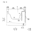
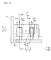
- the first reagent container setting part 221a is configured such that a height h1 at the upper end thereof on the Y2 side being the reagent-container-removing side is equal to or smaller than a half of a height h at the upper end of the first reagent container 3a when the first reagent container 3a is set in the first reagent container setting part 221 a. Accordingly, the first reagent container setting part 221 a allows the first reagent container 3a to be exposed on the Y2 side.
- a height h2 at the upper end of regions, of the inner wall face of the first reagent container setting part 221 a, that extend from a middle portion thereof toward the Y1 side is greater than the height h at the upper end of the first reagent container 3a when the first reagent container 3a is set in the first reagent container setting part 221 a. Accordingly, it is possible to set the first reagent container 3a in the first reagent-container retainer 4a in a more stable manner.
- the first reagent container setting part 221a is configured such that the first reagent container 3 a to which the aspirating tube holder 224a has been mounted can be set at a predetermined position without falling down.
- the reference position for the heights is the lowest position in the first reagent container 3a set in the first reagent container setting part 221 a.
- the second reagent container setting part 221b is configured such that the height h1 on the Y2 side being the reagent-container-removing side is equal to or smaller than a half of the height h of the second reagent container 3b when the second reagent container 3b is set in the second reagent container setting part 221b. Accordingly, the second reagent container setting part 221b allows the second reagent container 3b to be exposed on the Y2 side.
- the height h2 of regions, of the inner wall face of the second reagent container setting part 221b, that extend from a middle portion thereof toward the Y1 side is greater than the height h of the second reagent container 3b when the second reagent container 3b is set in the second reagent container setting part 221b.
- the second reagent container setting part 221b is configured such that the second reagent container 3b to which the aspirating tube holder 224b has been mounted can be set at a predetermined position without falling down.
- the reagent aspirator 222 is configured by a reagent aspirator 222a which aspirates a reagent from the first reagent container 3a, and a reagent aspirator 222b which aspirates a reagent from the second reagent container 3b.
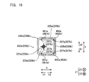
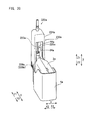
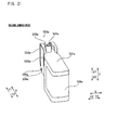
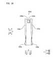
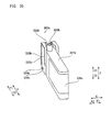
- the reagent aspirator 222a includes the aspirating tube 223a, the aspirating tube holder 224a, side faces 225a, an open portion 226a, and guide portions 227a (see FIG. 19 ) to be engaged with the guided rails 461a and 462a.
- Side faces 225a other than that on the Y2 side function as a cover portion 230a which covers the sides of the aspirating tube 223a.
- the cover portion 230a it is possible to prevent a hand of the user from coming into contact with the aspirating tube 223a.
- the aspirating tube holder 224a includes a hole 228a to be fitted with the claws 47a, and a packing 229a provided below the portion that holds the aspirating tube 223a.
- the reagent aspirator 222b includes the aspirating tube 223b, the aspirating tube holder 224b, side faces 225b, an open portion 226b, and guide portions 227b (see FIG. 19 ) to be engaged with the guided rails 451b and 452b.
- Side faces 225b other than that on the Y2 side function as a cover portion 230b which covers the sides of the aspirating tube 223b.
- the aspirating tube holder 224b includes a hole 228b to be fitted with the claws 46b, and a packing 229b provided below the portion that holds the aspirating tube 223b.
- the aspirating tube holder 224a is blue.
- the aspirating tube holder 224b is red.
- the color of the aspirating tube holder 224a is the same (blue) as the color of a part of the reagent indicating label of the first reagent container 3a.
- the color of the aspirating tube holder 224b is the same (red) as the color of a part of the reagent indicating label of the second reagent container 3b.
- the aspirating tube 223a of the reagent aspirator 222a and the aspirating tube 223b of the reagent aspirator 222b are connected to the reaction chamber 231a and the reaction chamber 231b via tubes 20 (see FIG. 3 ), respectively.
- the tubes 20 have lengths that allow the reagent aspirators 222a and 222b to be easily taken out of the first reagent-container retainer 4a and the second reagent-container retainer 4b, respectively.
- the aspirating tube holders 224a and 224b are formed from resin that allows radio waves pass therethrough.
- the reagent aspirators 222a and 222b have similar configurations except that the colors of the aspirating tube holders 224a and 224b are different. Therefore, in the following, only the reagent aspirator 222a will be described, and description of the reagent aspirator 222b will be omitted.
- the aspirating tube 223a is configured to aspirate a reagent in the first reagent container 3a.
- the aspirating tube 223a is formed so as to extend in the Z direction.
- the aspirating tube 223a has a length that reaches the vicinity of the deepest portion of the first reagent container 3a (see FIG. 4 ).
- the aspirating tube holder 224a is formed in a substantially rectangular parallelepiped shape. Inside the aspirating tube holder 224a, a cavity of a substantially rectangular parallelepiped shape is formed. The aspirating tube holder 224a is configured to hold the aspirating tube 223a.
- the open portion 226a is provided in the side face 225a on the Y2 side of the aspirating tube holder 224a. Specifically, the open portion 226a is provided in the side face 225a on the Y2 side, in a state where the first reagent container 3a to which the aspirating tube holder 224a has been mounted is set in the first reagent container setting part 221a.
- the open portion 226a it is possible to visually confirm the aspirating tube 223a through the open portion 226a, and thus, it is possible to visually confirm that the aspirating tube 223a has been caused to enter the opening 34a of the first reagent container 3 a by means of the guided portion 46a.
- the guide portions 227a have a function of being engaged with the guided rails 461 a and 462a to allow the aspirating tube holder 224a to linearly move in a sliding manner.
- the guide portions 227a are formed by portions, that are to come into contact with the guided rails 461 a and 462a, of the side faces 225a of the aspirating tube holder 224a.
- the guide portions 227a are provided on each of the X1 side and the X2 side.
- the guide portions 227a are provided on each of the Y1 side and the Y2 side.
- the guide portions 227a are formed so as to linearly extend along the Z direction.
- the guide portions 227a on the Y2 side are configured to be engaged with the guided rails 462a.
- the guide portions 227a on the Y1 side are configured to be engaged with the guided rails 461a.
- the guide portions 227a of the aspirating tube holder 224a are configured to, when they are to be engaged with the guided rails 461a and 462a, start to be engaged with the guided rails 461a and 462a of the first reagent-container retainer 4a, at a position on the first reagent container 3 a side relative to the leading end on the Z1 side of the aspirating tube 223a.
- the guided portion 46a of the first reagent-container retainer 4a is to be engaged with the guide portions 227a of the aspirating tube holder 224a, it is possible to prevent the leading end of the aspirating tube 223a from coming into contact with the first reagent-container retainer 4a.
- the guide portions 227a are formed in shapes that can be engaged with each of the guided portion 46a of the first reagent container 3 a and the guided portion 45b of the second reagent container 3b. Accordingly, it is possible to reduce the kinds of parts at the time of production of the sample analysis system 1.
- the aspirating tube holder 224a is set in the first reagent-container retainer 4a retaining the first reagent container 3a.
- the reaction chamber 231 includes the reaction chamber 231a in which a specimen for white blood cell classification is prepared, and the reaction chamber 231b in which a specimen for reticulocytes analysis is prepared.
- the reaction chamber 231 a is configured to heat a mixed solution of a sample and a reagent for white blood cell classification at a predetermined temperature.
- the reaction chamber 231b is configured to heat a mixed solution of a sample and a reagent for reticulocytes at a predetermined temperature.
- the detection unit 23 has a function of measuring, through flow cytometry, detection specimens sent from the reaction chambers 231 a and 231b. Detection results obtained by the detection unit 23 are transmitted to the control device 25. When the detection process ends, the detection specimens sent to the detection unit 23 is sent to the discharge unit 24.
- the discharge unit 24 is configured to discharge specimens having been subjected to measurement.
- the control device 25 is implemented by a personal computer, and includes a CPU, a storage section, and the like.
- the control device 25 analyzes measurement data transmitted from the detection unit 23, and generates analysis results regarding white blood cell classification and reticulocytes.
- the method for setting the second reagent container 3b is the same as the method for setting the first reagent container 3a. Thus, only the method for setting the first reagent container 3a is described here, and description of the method for setting the second reagent container 3b is omitted.
- the first reagent container 3a is set in the first reagent-container retainer 4a.
- the reagent aspirator 222a is mounted to the first reagent-container retainer 4a in which the first reagent container 3a has been set.
- the guide portions 227a of the aspirating tube holder 224a start to be engaged with the guided rails 461a and 462a of the first reagent-container retainer 4a at a position on the first reagent container 3a side relative to the position of the leading end of the aspirating tube 223a.
- the cutout 48a in the first reagent-container retainer 4a it is possible to prevent the aspirating tube 223a from coming into contact with the first reagent-container retainer 4a.
- the aspirating tube holder 224a is moved toward the Z2 side. Accordingly, mounting of the reagent aspirator 222a to the first reagent-container retainer 4a in which the first reagent container 3a has been set is completed. At this time, by the claws 47a of the first reagent-container retainer 4a being fitted into the hole 228a, the aspirating tube holder 224a is fixedly set in the first reagent-container retainer 4a retaining the first reagent container 3a.
- the first reagent-container retainer 4a in which the first reagent container 3a is retained and the reagent aspirator 222a has been set is disposed in the first reagent container setting part 221 a.
- the first reagent container 3a is set in the sample analyzer 2.
- the sample analysis system 1a will be described in which a first reagent container 303a and a second reagent container 303b are directly set in the first reagent container setting part 221 a and the second reagent container setting part 221 b, which is different from the first embodiment in which the first reagent container 3a and the second reagent container 3b are respectively retained in the first reagent-container retainer 4a and the second reagent-container retainer 4b and then are set in the sample analyzer 2.
- similar configurations to those in the first embodiment above are denoted by the same reference characters, and description thereof will be omitted.
- the first reagent container 303a includes a body portion 331a, an opening 332a, guided portions 333a, and claws 334a formed near the lower end of the first reagent container 303a.
- the first reagent container 303a includes a cutout 335a formed on the Y1 side and the Z1 side of the body portion 331a.
- a label 336a indicating reagent information is attached so as to cover the side face on the Y2 side. A part of the label 336a is blue.
- the opening 332a is provided on the Z1 side of the body portion 331a.
- the opening 332a is provided near the end on the Y1 side of the body portion 331a.
- the guided portions 333a are configured to guide the aspirating tube holder 224a relative to the first reagent container 303a such that the aspirating tube holder 224a is allowed to reach a state where the aspirating tube 223a has entered the first reagent container 303a or a state where the aspirating tube 223a has retreated from the first reagent container 303a.
- the guided portions 333a are respectively provided on the outer faces on the X1 side and the X2 side of the body portion 331a.
- the second reagent container 303b includes a body portion 331b, an opening 332b, guided portions 333b, and claws 334b formed near the lower end of the second reagent container 303b.
- the second reagent container 303b includes a cutout 335b formed on the Z1 side of the body portion 331b.
- a label 336b indicating reagent information is attached so as to cover the side face on the Y2 side. A part of the label 336b is red.
- the opening 332b is provided on the Z1 side of the body portion 331b.
- the opening 332b is provided near the end on the Y1 side of the body portion 331b.
- the guided portions 333b are configured to guide the aspirating tube holder 224b relative to the second reagent container 303b such that the aspirating tube holder 224b is allowed to reach a state where the aspirating tube 223b has entered the second reagent container 303b or a state where the aspirating tube 223b has retreated from the second reagent container 303b.
- the guided portions 333b are respectively provided on the outer faces on the X1 side and the X2 side of the body portion 331b.
- the present disclosure is applied to a sample analyzer which performs a test on a sample such as blood.
- a sample analyzer which performs tests on a sample such as urine and genes.
- the aspirating tube holder includes an opening on the Y2 side.
- the present disclosure is not limited thereto.
- the aspirating tube holder may not include an opening on the Y2 side.
- the present disclosure is not limited thereto. In the present disclosure, one kind, or three or more kinds of reagent containers may be set in the sample analysis system.
- the color of the aspirating tube holder and the color of a part of the reagent container are the same.
- the present disclosure is not limited thereto.
- the color of the aspirating tube holder and the color of a part of the reagent container may be similar to each other. Similar colors here means that two colors are visually recognized as of the same color type as in: blue-type colors such as blue, light blue, and purple, red-type colors such as red, orange, and pink, and the like.
Landscapes
- Chemical & Material Sciences (AREA)
- Health & Medical Sciences (AREA)
- Analytical Chemistry (AREA)
- Clinical Laboratory Science (AREA)
- Chemical Kinetics & Catalysis (AREA)
- General Health & Medical Sciences (AREA)
- Life Sciences & Earth Sciences (AREA)
- Physics & Mathematics (AREA)
- Biochemistry (AREA)
- General Physics & Mathematics (AREA)
- Immunology (AREA)
- Pathology (AREA)
- Medicinal Chemistry (AREA)
- Hematology (AREA)
- Automatic Analysis And Handling Materials Therefor (AREA)
Applications Claiming Priority (1)
| Application Number | Priority Date | Filing Date | Title |
|---|---|---|---|
| JP2014069375A JP6130320B2 (ja) | 2014-03-28 | 2014-03-28 | 検体分析装置および試薬容器 |
Publications (2)
| Publication Number | Publication Date |
|---|---|
| EP2927697A1 true EP2927697A1 (fr) | 2015-10-07 |
| EP2927697B1 EP2927697B1 (fr) | 2022-04-06 |
Family
ID=52991451
Family Applications (1)
| Application Number | Title | Priority Date | Filing Date |
|---|---|---|---|
| EP15159910.7A Active EP2927697B1 (fr) | 2014-03-28 | 2015-03-19 | Analyseur d'échantillon |
Country Status (4)
| Country | Link |
|---|---|
| US (1) | US9795967B2 (fr) |
| EP (1) | EP2927697B1 (fr) |
| JP (1) | JP6130320B2 (fr) |
| CN (1) | CN104950117B (fr) |
Families Citing this family (10)
| Publication number | Priority date | Publication date | Assignee | Title |
|---|---|---|---|---|
| US9835640B2 (en) | 2015-02-13 | 2017-12-05 | Abbott Laboratories | Automated storage modules for diagnostic analyzer liquids and related systems and methods |
| JP6788965B2 (ja) | 2015-12-17 | 2020-11-25 | シスメックス株式会社 | 検体分析装置および検体分析方法 |
| JP6937116B2 (ja) * | 2016-12-15 | 2021-09-22 | シスメックス株式会社 | 前処理装置及び前処理方法 |
| CN107703322B (zh) * | 2017-06-15 | 2024-06-04 | 迈克医疗电子有限公司 | 试剂吸样机构及样本分析仪 |
| EP3779469B1 (fr) * | 2018-04-12 | 2023-06-21 | Hitachi High-Tech Corporation | Dispositif d'analyse d'électrolyte |
| US12123847B2 (en) * | 2018-10-31 | 2024-10-22 | Hitachi High-Tech Corporation | Electrolyte analyzing device |
| JP7408385B2 (ja) * | 2019-12-27 | 2024-01-05 | シスメックス株式会社 | 試薬容器 |
| CN113083392B (zh) * | 2021-04-15 | 2022-10-11 | 南京艾尔普再生医学科技有限公司 | 一种冻存管旋盖分液装置 |
| CN115902248A (zh) * | 2021-08-26 | 2023-04-04 | 深圳市帝迈生物技术有限公司 | 样本分析仪以及试剂供给装置 |
| CN115932292A (zh) * | 2021-08-26 | 2023-04-07 | 深圳市帝迈生物技术有限公司 | 试剂供给装置、试剂更换方法以及样本分析仪 |
Citations (4)
| Publication number | Priority date | Publication date | Assignee | Title |
|---|---|---|---|---|
| WO1991001007A1 (fr) * | 1989-07-07 | 1991-01-24 | Baxter International Inc. | Assemblage servant a retirer les substances residuaires de recipients fermes contenant des echantillons |
| DE4314657A1 (de) * | 1993-05-04 | 1994-11-10 | Friedhelm Sehrt | Sicherheitsvorrichtung zur sicheren Handhabung flüssiger Stoffe mittels einer Spritze insbesondere zum Dosieren und Abfüllen gesundheitsgefährdender Flüssigkeiten |
| US20100080732A1 (en) * | 2008-09-26 | 2010-04-01 | Sysmex Corporation | Analyzer and liquid container |
| WO2011105247A1 (fr) | 2010-02-26 | 2011-09-01 | シスメックス株式会社 | Dispositif d'analyse et récipient à réactifs |
Family Cites Families (8)
| Publication number | Priority date | Publication date | Assignee | Title |
|---|---|---|---|---|
| US5641006A (en) * | 1995-07-13 | 1997-06-24 | Chiron Diagnostics Corporation | Liquid supply apparatus and method of operation |
| US5875921A (en) * | 1997-03-12 | 1999-03-02 | Now Technologies, Inc. | Liquid chemical dispensing system with sensor |
| DE19963032A1 (de) * | 1999-12-24 | 2001-06-28 | Roche Diagnostics Gmbh | System zur Bearbeitung von Proben in einer Mehrkammeranordnung |
| JP4658411B2 (ja) * | 2001-09-11 | 2011-03-23 | シスメックス株式会社 | 流路接続機構及びこれを備えた試薬ホルダ |
| US7186378B2 (en) * | 2003-07-18 | 2007-03-06 | Dade Behring Inc. | Liquid sampling probe and cleaning fluidics system |
| EP2413136B1 (fr) * | 2003-07-18 | 2013-07-03 | Bio-Rad Laboratories, Inc. | Système et procédé pour la détection multi-analytes |
| US8658417B2 (en) * | 2009-09-15 | 2014-02-25 | Qiagen Gaithersburg, Inc. | Multiple-input analytical system |
| JP5710328B2 (ja) * | 2011-03-23 | 2015-04-30 | シスメックス株式会社 | 血球計数装置 |
-
2014
- 2014-03-28 JP JP2014069375A patent/JP6130320B2/ja active Active
-
2015
- 2015-03-19 EP EP15159910.7A patent/EP2927697B1/fr active Active
- 2015-03-20 US US14/664,182 patent/US9795967B2/en active Active
- 2015-03-25 CN CN201510132643.6A patent/CN104950117B/zh active Active
Patent Citations (5)
| Publication number | Priority date | Publication date | Assignee | Title |
|---|---|---|---|---|
| WO1991001007A1 (fr) * | 1989-07-07 | 1991-01-24 | Baxter International Inc. | Assemblage servant a retirer les substances residuaires de recipients fermes contenant des echantillons |
| DE4314657A1 (de) * | 1993-05-04 | 1994-11-10 | Friedhelm Sehrt | Sicherheitsvorrichtung zur sicheren Handhabung flüssiger Stoffe mittels einer Spritze insbesondere zum Dosieren und Abfüllen gesundheitsgefährdender Flüssigkeiten |
| US20100080732A1 (en) * | 2008-09-26 | 2010-04-01 | Sysmex Corporation | Analyzer and liquid container |
| WO2011105247A1 (fr) | 2010-02-26 | 2011-09-01 | シスメックス株式会社 | Dispositif d'analyse et récipient à réactifs |
| US20120321513A1 (en) * | 2010-02-26 | 2012-12-20 | Takaaki Nagai | Analysis device and reagent container |
Also Published As
| Publication number | Publication date |
|---|---|
| CN104950117A (zh) | 2015-09-30 |
| CN104950117B (zh) | 2018-01-02 |
| JP6130320B2 (ja) | 2017-05-17 |
| JP2015190901A (ja) | 2015-11-02 |
| US9795967B2 (en) | 2017-10-24 |
| US20150273466A1 (en) | 2015-10-01 |
| EP2927697B1 (fr) | 2022-04-06 |
Similar Documents
| Publication | Publication Date | Title |
|---|---|---|
| EP2927697B1 (fr) | Analyseur d'échantillon | |
| US11480778B2 (en) | Automated microscopic cell analysis | |
| US20250249449A1 (en) | Automated microscopic cell analysis | |
| US7256045B2 (en) | Analyzer with sample quality measurement, and method | |
| EP3482189B1 (fr) | Analyse automatisée de cellules microscopiques | |
| EP2610621B1 (fr) | Analyseur de cellules sanguines, procédé d'analyse de cellules sanguines et support de stockage non transitoire | |
| CN101983339B (zh) | 制样装置与制样方法以及细胞分析装置与细胞分析方法 | |
| US20180272331A1 (en) | Device for preparing and dispensing biological sample | |
| US20040081583A1 (en) | Fluid analyzer | |
| CN105874053A (zh) | 配有一体化的反应和检测装置的多槽试杯 | |
| CN101688874A (zh) | 标本容器 | |
| EP3673271B1 (fr) | Système de distribution de substance pour instrument d'analyse d'échantillon biologique | |
| KR20150056479A (ko) | 일체화된 반응 및 검출 수단을 구비한 시험 장치에 사용되는 스테이션 | |
| JP2004301843A (ja) | 固定多機能プローブを有する分析装置 | |
| JP2002328080A (ja) | 生体液の分析のためのシステム | |
| JP2004301844A (ja) | 分析装置用プローブガイド付き検査要素ホルダー | |
| EP2136210B1 (fr) | Analyseur d'échantillon de fluide corporel | |
| KR102757357B9 (ko) | 생체 분석물의 정량적 샘플링을 통한 현장 검사 장치 | |
| US12399189B2 (en) | Immunoassay device and immunoassay method | |
| EP4491272A1 (fr) | Flacon et cartouche de test le comprenant | |
| US20220155291A1 (en) | Immunoassay device and immunoassay method | |
| JP4352037B2 (ja) | 検体検査装置の前処理操作機構および検体装着ユニット | |
| US20230173478A1 (en) | Mini-pipette | |
| US20260056221A1 (en) | Method for mixing fluids | |
| CN121816504A (zh) | 用于检测荧光的液体处理装置和方法 |
Legal Events
| Date | Code | Title | Description |
|---|---|---|---|
| PUAI | Public reference made under article 153(3) epc to a published international application that has entered the european phase |
Free format text: ORIGINAL CODE: 0009012 |
|
| AK | Designated contracting states |
Kind code of ref document: A1 Designated state(s): AL AT BE BG CH CY CZ DE DK EE ES FI FR GB GR HR HU IE IS IT LI LT LU LV MC MK MT NL NO PL PT RO RS SE SI SK SM TR |
|
| AX | Request for extension of the european patent |
Extension state: BA ME |
|
| 17P | Request for examination filed |
Effective date: 20160330 |
|
| RBV | Designated contracting states (corrected) |
Designated state(s): AL AT BE BG CH CY CZ DE DK EE ES FI FR GB GR HR HU IE IS IT LI LT LU LV MC MK MT NL NO PL PT RO RS SE SI SK SM TR |
|
| STAA | Information on the status of an ep patent application or granted ep patent |
Free format text: STATUS: EXAMINATION IS IN PROGRESS |
|
| 17Q | First examination report despatched |
Effective date: 20180718 |
|
| GRAP | Despatch of communication of intention to grant a patent |
Free format text: ORIGINAL CODE: EPIDOSNIGR1 |
|
| STAA | Information on the status of an ep patent application or granted ep patent |
Free format text: STATUS: GRANT OF PATENT IS INTENDED |
|
| INTG | Intention to grant announced |
Effective date: 20211014 |
|
| GRAS | Grant fee paid |
Free format text: ORIGINAL CODE: EPIDOSNIGR3 |
|
| GRAA | (expected) grant |
Free format text: ORIGINAL CODE: 0009210 |
|
| STAA | Information on the status of an ep patent application or granted ep patent |
Free format text: STATUS: THE PATENT HAS BEEN GRANTED |
|
| AK | Designated contracting states |
Kind code of ref document: B1 Designated state(s): AL AT BE BG CH CY CZ DE DK EE ES FI FR GB GR HR HU IE IS IT LI LT LU LV MC MK MT NL NO PL PT RO RS SE SI SK SM TR |
|
| REG | Reference to a national code |
Ref country code: GB Ref legal event code: FG4D |
|
| REG | Reference to a national code |
Ref country code: CH Ref legal event code: EP |
|
| REG | Reference to a national code |
Ref country code: AT Ref legal event code: REF Ref document number: 1481825 Country of ref document: AT Kind code of ref document: T Effective date: 20220415 |
|
| REG | Reference to a national code |
Ref country code: IE Ref legal event code: FG4D |
|
| REG | Reference to a national code |
Ref country code: DE Ref legal event code: R096 Ref document number: 602015077991 Country of ref document: DE |
|
| REG | Reference to a national code |
Ref country code: LT Ref legal event code: MG9D |
|
| REG | Reference to a national code |
Ref country code: NL Ref legal event code: MP Effective date: 20220406 |
|
| REG | Reference to a national code |
Ref country code: AT Ref legal event code: MK05 Ref document number: 1481825 Country of ref document: AT Kind code of ref document: T Effective date: 20220406 |
|
| PG25 | Lapsed in a contracting state [announced via postgrant information from national office to epo] |
Ref country code: NL Free format text: LAPSE BECAUSE OF FAILURE TO SUBMIT A TRANSLATION OF THE DESCRIPTION OR TO PAY THE FEE WITHIN THE PRESCRIBED TIME-LIMIT Effective date: 20220406 |
|
| PG25 | Lapsed in a contracting state [announced via postgrant information from national office to epo] |
Ref country code: SE Free format text: LAPSE BECAUSE OF FAILURE TO SUBMIT A TRANSLATION OF THE DESCRIPTION OR TO PAY THE FEE WITHIN THE PRESCRIBED TIME-LIMIT Effective date: 20220406 Ref country code: PT Free format text: LAPSE BECAUSE OF FAILURE TO SUBMIT A TRANSLATION OF THE DESCRIPTION OR TO PAY THE FEE WITHIN THE PRESCRIBED TIME-LIMIT Effective date: 20220808 Ref country code: NO Free format text: LAPSE BECAUSE OF FAILURE TO SUBMIT A TRANSLATION OF THE DESCRIPTION OR TO PAY THE FEE WITHIN THE PRESCRIBED TIME-LIMIT Effective date: 20220706 Ref country code: LT Free format text: LAPSE BECAUSE OF FAILURE TO SUBMIT A TRANSLATION OF THE DESCRIPTION OR TO PAY THE FEE WITHIN THE PRESCRIBED TIME-LIMIT Effective date: 20220406 Ref country code: HR Free format text: LAPSE BECAUSE OF FAILURE TO SUBMIT A TRANSLATION OF THE DESCRIPTION OR TO PAY THE FEE WITHIN THE PRESCRIBED TIME-LIMIT Effective date: 20220406 Ref country code: GR Free format text: LAPSE BECAUSE OF FAILURE TO SUBMIT A TRANSLATION OF THE DESCRIPTION OR TO PAY THE FEE WITHIN THE PRESCRIBED TIME-LIMIT Effective date: 20220707 Ref country code: FI Free format text: LAPSE BECAUSE OF FAILURE TO SUBMIT A TRANSLATION OF THE DESCRIPTION OR TO PAY THE FEE WITHIN THE PRESCRIBED TIME-LIMIT Effective date: 20220406 Ref country code: ES Free format text: LAPSE BECAUSE OF FAILURE TO SUBMIT A TRANSLATION OF THE DESCRIPTION OR TO PAY THE FEE WITHIN THE PRESCRIBED TIME-LIMIT Effective date: 20220406 Ref country code: BG Free format text: LAPSE BECAUSE OF FAILURE TO SUBMIT A TRANSLATION OF THE DESCRIPTION OR TO PAY THE FEE WITHIN THE PRESCRIBED TIME-LIMIT Effective date: 20220706 Ref country code: AT Free format text: LAPSE BECAUSE OF FAILURE TO SUBMIT A TRANSLATION OF THE DESCRIPTION OR TO PAY THE FEE WITHIN THE PRESCRIBED TIME-LIMIT Effective date: 20220406 |
|
| PG25 | Lapsed in a contracting state [announced via postgrant information from national office to epo] |
Ref country code: RS Free format text: LAPSE BECAUSE OF FAILURE TO SUBMIT A TRANSLATION OF THE DESCRIPTION OR TO PAY THE FEE WITHIN THE PRESCRIBED TIME-LIMIT Effective date: 20220406 Ref country code: PL Free format text: LAPSE BECAUSE OF FAILURE TO SUBMIT A TRANSLATION OF THE DESCRIPTION OR TO PAY THE FEE WITHIN THE PRESCRIBED TIME-LIMIT Effective date: 20220406 Ref country code: LV Free format text: LAPSE BECAUSE OF FAILURE TO SUBMIT A TRANSLATION OF THE DESCRIPTION OR TO PAY THE FEE WITHIN THE PRESCRIBED TIME-LIMIT Effective date: 20220406 Ref country code: IS Free format text: LAPSE BECAUSE OF FAILURE TO SUBMIT A TRANSLATION OF THE DESCRIPTION OR TO PAY THE FEE WITHIN THE PRESCRIBED TIME-LIMIT Effective date: 20220806 |
|
| REG | Reference to a national code |
Ref country code: DE Ref legal event code: R097 Ref document number: 602015077991 Country of ref document: DE |
|
| PG25 | Lapsed in a contracting state [announced via postgrant information from national office to epo] |
Ref country code: SM Free format text: LAPSE BECAUSE OF FAILURE TO SUBMIT A TRANSLATION OF THE DESCRIPTION OR TO PAY THE FEE WITHIN THE PRESCRIBED TIME-LIMIT Effective date: 20220406 Ref country code: SK Free format text: LAPSE BECAUSE OF FAILURE TO SUBMIT A TRANSLATION OF THE DESCRIPTION OR TO PAY THE FEE WITHIN THE PRESCRIBED TIME-LIMIT Effective date: 20220406 Ref country code: RO Free format text: LAPSE BECAUSE OF FAILURE TO SUBMIT A TRANSLATION OF THE DESCRIPTION OR TO PAY THE FEE WITHIN THE PRESCRIBED TIME-LIMIT Effective date: 20220406 Ref country code: EE Free format text: LAPSE BECAUSE OF FAILURE TO SUBMIT A TRANSLATION OF THE DESCRIPTION OR TO PAY THE FEE WITHIN THE PRESCRIBED TIME-LIMIT Effective date: 20220406 Ref country code: DK Free format text: LAPSE BECAUSE OF FAILURE TO SUBMIT A TRANSLATION OF THE DESCRIPTION OR TO PAY THE FEE WITHIN THE PRESCRIBED TIME-LIMIT Effective date: 20220406 Ref country code: CZ Free format text: LAPSE BECAUSE OF FAILURE TO SUBMIT A TRANSLATION OF THE DESCRIPTION OR TO PAY THE FEE WITHIN THE PRESCRIBED TIME-LIMIT Effective date: 20220406 |
|
| PLBE | No opposition filed within time limit |
Free format text: ORIGINAL CODE: 0009261 |
|
| STAA | Information on the status of an ep patent application or granted ep patent |
Free format text: STATUS: NO OPPOSITION FILED WITHIN TIME LIMIT |
|
| 26N | No opposition filed |
Effective date: 20230110 |
|
| PG25 | Lapsed in a contracting state [announced via postgrant information from national office to epo] |
Ref country code: AL Free format text: LAPSE BECAUSE OF FAILURE TO SUBMIT A TRANSLATION OF THE DESCRIPTION OR TO PAY THE FEE WITHIN THE PRESCRIBED TIME-LIMIT Effective date: 20220406 |
|
| PG25 | Lapsed in a contracting state [announced via postgrant information from national office to epo] |
Ref country code: SI Free format text: LAPSE BECAUSE OF FAILURE TO SUBMIT A TRANSLATION OF THE DESCRIPTION OR TO PAY THE FEE WITHIN THE PRESCRIBED TIME-LIMIT Effective date: 20220406 |
|
| PG25 | Lapsed in a contracting state [announced via postgrant information from national office to epo] |
Ref country code: MC Free format text: LAPSE BECAUSE OF FAILURE TO SUBMIT A TRANSLATION OF THE DESCRIPTION OR TO PAY THE FEE WITHIN THE PRESCRIBED TIME-LIMIT Effective date: 20220406 |
|
| REG | Reference to a national code |
Ref country code: CH Ref legal event code: PL |
|
| GBPC | Gb: european patent ceased through non-payment of renewal fee |
Effective date: 20230319 |
|
| REG | Reference to a national code |
Ref country code: BE Ref legal event code: MM Effective date: 20230331 |
|
| PG25 | Lapsed in a contracting state [announced via postgrant information from national office to epo] |
Ref country code: LU Free format text: LAPSE BECAUSE OF NON-PAYMENT OF DUE FEES Effective date: 20230319 |
|
| REG | Reference to a national code |
Ref country code: IE Ref legal event code: MM4A |
|
| PG25 | Lapsed in a contracting state [announced via postgrant information from national office to epo] |
Ref country code: GB Free format text: LAPSE BECAUSE OF NON-PAYMENT OF DUE FEES Effective date: 20230319 |
|
| PG25 | Lapsed in a contracting state [announced via postgrant information from national office to epo] |
Ref country code: LI Free format text: LAPSE BECAUSE OF NON-PAYMENT OF DUE FEES Effective date: 20230331 Ref country code: IT Free format text: LAPSE BECAUSE OF FAILURE TO SUBMIT A TRANSLATION OF THE DESCRIPTION OR TO PAY THE FEE WITHIN THE PRESCRIBED TIME-LIMIT Effective date: 20220406 Ref country code: IE Free format text: LAPSE BECAUSE OF NON-PAYMENT OF DUE FEES Effective date: 20230319 Ref country code: GB Free format text: LAPSE BECAUSE OF NON-PAYMENT OF DUE FEES Effective date: 20230319 Ref country code: FR Free format text: LAPSE BECAUSE OF NON-PAYMENT OF DUE FEES Effective date: 20230331 Ref country code: CH Free format text: LAPSE BECAUSE OF NON-PAYMENT OF DUE FEES Effective date: 20230331 |
|
| PG25 | Lapsed in a contracting state [announced via postgrant information from national office to epo] |
Ref country code: BE Free format text: LAPSE BECAUSE OF NON-PAYMENT OF DUE FEES Effective date: 20230331 |
|
| PG25 | Lapsed in a contracting state [announced via postgrant information from national office to epo] |
Ref country code: BG Free format text: LAPSE BECAUSE OF FAILURE TO SUBMIT A TRANSLATION OF THE DESCRIPTION OR TO PAY THE FEE WITHIN THE PRESCRIBED TIME-LIMIT Effective date: 20220406 |
|
| PG25 | Lapsed in a contracting state [announced via postgrant information from national office to epo] |
Ref country code: BG Free format text: LAPSE BECAUSE OF FAILURE TO SUBMIT A TRANSLATION OF THE DESCRIPTION OR TO PAY THE FEE WITHIN THE PRESCRIBED TIME-LIMIT Effective date: 20220406 |
|
| PG25 | Lapsed in a contracting state [announced via postgrant information from national office to epo] |
Ref country code: CY Free format text: LAPSE BECAUSE OF FAILURE TO SUBMIT A TRANSLATION OF THE DESCRIPTION OR TO PAY THE FEE WITHIN THE PRESCRIBED TIME-LIMIT; INVALID AB INITIO Effective date: 20150319 |
|
| PG25 | Lapsed in a contracting state [announced via postgrant information from national office to epo] |
Ref country code: HU Free format text: LAPSE BECAUSE OF FAILURE TO SUBMIT A TRANSLATION OF THE DESCRIPTION OR TO PAY THE FEE WITHIN THE PRESCRIBED TIME-LIMIT; INVALID AB INITIO Effective date: 20150319 |
|
| PG25 | Lapsed in a contracting state [announced via postgrant information from national office to epo] |
Ref country code: TR Free format text: LAPSE BECAUSE OF FAILURE TO SUBMIT A TRANSLATION OF THE DESCRIPTION OR TO PAY THE FEE WITHIN THE PRESCRIBED TIME-LIMIT Effective date: 20220406 |
|
| PGFP | Annual fee paid to national office [announced via postgrant information from national office to epo] |
Ref country code: DE Payment date: 20260128 Year of fee payment: 12 |