EP2927773B1 - Système de régulation de pression dans un tuyau d'approvisionnement en fluides - Google Patents
Système de régulation de pression dans un tuyau d'approvisionnement en fluides Download PDFInfo
- Publication number
- EP2927773B1 EP2927773B1 EP13811579.5A EP13811579A EP2927773B1 EP 2927773 B1 EP2927773 B1 EP 2927773B1 EP 13811579 A EP13811579 A EP 13811579A EP 2927773 B1 EP2927773 B1 EP 2927773B1
- Authority
- EP
- European Patent Office
- Prior art keywords
- valve
- pressure
- chamber
- tank
- cylinder
- Prior art date
- Legal status (The legal status is an assumption and is not a legal conclusion. Google has not performed a legal analysis and makes no representation as to the accuracy of the status listed.)
- Active
Links
Images

Classifications
-
- G—PHYSICS
- G05—CONTROLLING; REGULATING
- G05D—SYSTEMS FOR CONTROLLING OR REGULATING NON-ELECTRIC VARIABLES
- G05D16/00—Control of fluid pressure
- G05D16/14—Control of fluid pressure with auxiliary non-electric power
- G05D16/16—Control of fluid pressure with auxiliary non-electric power derived from the controlled fluid
- G05D16/166—Control of fluid pressure with auxiliary non-electric power derived from the controlled fluid using pistons within the main valve
-
- G—PHYSICS
- G05—CONTROLLING; REGULATING
- G05D—SYSTEMS FOR CONTROLLING OR REGULATING NON-ELECTRIC VARIABLES
- G05D16/00—Control of fluid pressure
- G05D16/20—Control of fluid pressure characterised by the use of electric means
- G05D16/2093—Control of fluid pressure characterised by the use of electric means with combination of electric and non-electric auxiliary power
- G05D16/2097—Control of fluid pressure characterised by the use of electric means with combination of electric and non-electric auxiliary power using pistons within the main valve
-
- F—MECHANICAL ENGINEERING; LIGHTING; HEATING; WEAPONS; BLASTING
- F16—ENGINEERING ELEMENTS AND UNITS; GENERAL MEASURES FOR PRODUCING AND MAINTAINING EFFECTIVE FUNCTIONING OF MACHINES OR INSTALLATIONS; THERMAL INSULATION IN GENERAL
- F16K—VALVES; TAPS; COCKS; ACTUATING-FLOATS; DEVICES FOR VENTING OR AERATING
- F16K31/00—Actuating devices; Operating means; Releasing devices
- F16K31/12—Actuating devices; Operating means; Releasing devices actuated by fluid
- F16K31/122—Actuating devices; Operating means; Releasing devices actuated by fluid the fluid acting on a piston
- F16K31/1223—Actuating devices; Operating means; Releasing devices actuated by fluid the fluid acting on a piston one side of the piston being acted upon by the circulating fluid
-
- F—MECHANICAL ENGINEERING; LIGHTING; HEATING; WEAPONS; BLASTING
- F16—ENGINEERING ELEMENTS AND UNITS; GENERAL MEASURES FOR PRODUCING AND MAINTAINING EFFECTIVE FUNCTIONING OF MACHINES OR INSTALLATIONS; THERMAL INSULATION IN GENERAL
- F16K—VALVES; TAPS; COCKS; ACTUATING-FLOATS; DEVICES FOR VENTING OR AERATING
- F16K31/00—Actuating devices; Operating means; Releasing devices
- F16K31/12—Actuating devices; Operating means; Releasing devices actuated by fluid
- F16K31/36—Actuating devices; Operating means; Releasing devices actuated by fluid in which fluid from the circuit is constantly supplied to the fluid motor
- F16K31/363—Actuating devices; Operating means; Releasing devices actuated by fluid in which fluid from the circuit is constantly supplied to the fluid motor the fluid acting on a piston
-
- Y—GENERAL TAGGING OF NEW TECHNOLOGICAL DEVELOPMENTS; GENERAL TAGGING OF CROSS-SECTIONAL TECHNOLOGIES SPANNING OVER SEVERAL SECTIONS OF THE IPC; TECHNICAL SUBJECTS COVERED BY FORMER USPC CROSS-REFERENCE ART COLLECTIONS [XRACs] AND DIGESTS
- Y10—TECHNICAL SUBJECTS COVERED BY FORMER USPC
- Y10T—TECHNICAL SUBJECTS COVERED BY FORMER US CLASSIFICATION
- Y10T137/00—Fluid handling
- Y10T137/7722—Line condition change responsive valves
- Y10T137/7758—Pilot or servo controlled
- Y10T137/7762—Fluid pressure type
-
- Y—GENERAL TAGGING OF NEW TECHNOLOGICAL DEVELOPMENTS; GENERAL TAGGING OF CROSS-SECTIONAL TECHNOLOGIES SPANNING OVER SEVERAL SECTIONS OF THE IPC; TECHNICAL SUBJECTS COVERED BY FORMER USPC CROSS-REFERENCE ART COLLECTIONS [XRACs] AND DIGESTS
- Y10—TECHNICAL SUBJECTS COVERED BY FORMER USPC
- Y10T—TECHNICAL SUBJECTS COVERED BY FORMER US CLASSIFICATION
- Y10T137/00—Fluid handling
- Y10T137/7722—Line condition change responsive valves
- Y10T137/7781—With separate connected fluid reactor surface
- Y10T137/7793—With opening bias [e.g., pressure regulator]
Definitions
- the invention relates to a system for regulating pressure in a fluid supply pipe that can be applied for automatically regulating the water distribution pressure in a network, for example in a consumer network.
- the invention also relates to a device particularly suitable for implementing the aforesaid system.
- Hydraulic valves are sometimes used to regulate pressure in a supply pipe. These valves can be operated manually or by means of actuators that need a source of power, such as electric power.
- valves When these valves are installed in remote sites with respect to the power grid, electric generators have to be taken to the site where the valves are located to power the corresponding actuators and to enable operating said valves.
- Patent documents US 3734120 and US 3769998 disclose also similar systems for regulating pressure in a fluid supply pipe.
- a first objective of the invention is therefore a system whereby the valve can be operated, for example to regulate the pressure of the fluid to a predetermined set point pressure, which can further be selected as needed and in a very simple manner.
- Another objective of the invention is a system that offers the possibility of regulating the pressure of the fluid automatically and according to two different set point pressures, for example for regulating the pressure of the fluid to a first daytime set point pressure, i.e., during peak hours; and for regulating the pressure of the fluid to a lower second nighttime set point pressure, during off-peak hours, to reduce losses of the distribution network downstream of the valve.
- the system must furthermore be compatible with the valves that are used, i.e., no adjustments need to be made in existing installations.
- a secondary objective of the invention is for the system to allow different ways of putting it into practice in which the set point pressure or pressures can be changed and pressure can be modulated remotely, for example from a control center or a local control system by means of an automaton.
- the system of the invention is a system according to the claim 1.
- the system comprises a hydraulic valve with mechanical means for actuation thereof and a double acting piston cylinder, with first and second chambers and a rod connected to the mechanical actuation means of said valve, the system further comprising transmission means for transmitting the instantaneous hydraulic pressure in at least one point of the pipe to one of the chambers of the cylinder.
- the invention is essentially characterized in that the chamber of the cylinder, the pressure of which acts on the piston to move the rod in the direction for closing the valve, is the chamber that communicates with the transmission means for transmitting the instantaneous hydraulic pressure of the pipe; whereas the chamber of the cylinder, the pressure of which acts on the piston to move the rod in the direction for opening the valve, is connected to an energy accumulator accumulating energy in the form of pressurized gas at a predetermined pressure P0, the system comprising means for regulating said determined pressure P0.
- the energy accumulator accumulating energy in the form of pressurized gas is formed by a first chamber of a hydropneumatic tank containing the gas, a second chamber of said hydropneumatic tank being hydraulically connected to the supply pipe at a point upstream of the valve.
- the hydropneumatic tank is a hydropneumatic membrane tank.
- the transmission means for transmitting the instantaneous hydraulic pressure at a point of the pipe to the chamber of the cylinder comprise a tank connected to the pipe and housing an expandable cavity holding a driving fluid in a leak-tight manner with respect to the inside of said tank, said expandable cavity being connected to the corresponding chamber of the cylinder.
- the system comprises an electric valve for selectively setting up a hydraulic connection, by means of respective conduits, between said tank and the supply pipe at two different points, one of which is located upstream of the valve and the other is located downstream of said valve.
- connection between the second chamber of the hydropneumatic tank and the point of the pipe arranged upstream of the valve preferably comprises a reducing valve and a three-way valve arranged between said connection point and the reducing valve, said second chamber being connected to the outlet of the reducing valve and the conduit for connecting with the tank being connected to a free port of the three-way valve.
- the system comprises a pressure transducer connected to the outlet of the first chamber and a set of electric valves connected to the inlet of the second chamber of the hydropneumatic tank, controlled by a control system that can be controlled remotely and with means for comparing the value of the gas pressure at the outlet of the first chamber, obtained by means of the pressure transducer, with a set point pressure value P1 in time real, and that can generate a control signal in response to said comparison operation suitable for acting on the set of electric valves.
- the gas is nitrogen.
- a device for regulating pressure in a fluid supply pipe comprises a support body with means for the firm fixing thereof to the body of a valve, such as a butterfly valve, is disclosed; there being attached to the support body a double acting piston cylinder that can rotate about a horizontal axis in a position for mounting the support body on the valve, with first and second chambers connected to the outside and a rod prepared for the articulated connection thereof to a mechanism; and an energy accumulator accumulating energy in the form of pressurized gas, communicated with the first chamber of the cylinder.
- a tank housing an expandable cavity holding a driving fluid in a leak-tight manner with respect to the inside of said tank, connected to the second chamber of the cylinder, can also be optionally attached to the support body, the tank being equipped with means for hydraulically connecting it to an external feeding point.
- the energy accumulator is a first chamber of a hydropneumatic tank equipped with means for hydraulically connecting its second chamber to an external fluid feeding point.
- the system 1 for regulating pressure illustrated in Figure 1 is suitable for maintaining an optimal daytime pressure P1 in a supply pipe 3, downstream of the valve 2, and reducing it to a nighttime pressure P0 for reducing the volume of losses.
- the valve 2 is a butterfly valve with mechanical means 4 for actuation thereof, formed in the example by a lower lever arm.
- This lever arm is connected to the rod 6 of a double acting piston cylinder 5, such that the linear movement of the piston, and therefore of the rod 6, in one direction or the other will cause the rotation of the lever arm in one direction or the other, operating the valve 2 for opening or closing it.
- the cylinder 5 of the system 1 of the example basically consists of a barrel-type cylinder and a moveable piston connected to the aforesaid rod 6.
- the barrel-type cylinder is closed at both ends, one of which is provided with a perforation where the rod 6 projects.
- the piston splits the inside of the barrel-type cylinder into two chambers 5a and 5b.
- the system of Figures 1 to 3 uses a compressed gas 10 as a source of power to move the rod 6 of the cylinder 5 in one direction, whereas it uses a driving fluid 9, such as an oil, to move the rod 6 in the opposite direction.
- a compressed gas 10 as a source of power to move the rod 6 of the cylinder 5 in one direction
- a driving fluid 9 such as an oil
- This cylinder 5 can be mounted in an articulated manner to the body of the valve 2, which can in turn support other important components of the system.
- This expandable cavity 8 is housed in a rigid tank 7a connected to the pipe 3 and therefore full of water at a pressure the value of which will be established by the pressure of the water circulating at that time through the section of the pipe 3 to which the tank 7a is connected.
- the expandable cavity 8 is formed by an elastic bladder inside the tank 7a, which is leak-tight with respect to the content of this tank 7a.
- the system 1 comprises a first electric valve 13 for selectively setting up a hydraulic connection, by means of respective conduits 14 and 15, between said tank 7a and the supply pipe 3 at two different points 3a, 3b.
- Point 3a is located upstream of the valve 2 and point 3b is located downstream of said valve 2.
- These conduits 14 and 15 can be formed, for example, by 0.25 inch, i.e., 0.6 cm, polyamide tubes.
- the chamber 5a of the cylinder 5 the pressure of which acts on the piston to move the rod in the direction for opening the valve 2, communicates with a first chamber 17 of a hydropneumatic tank 16 containing the gas 10 used as a source of power to move said rod 6.
- the hydropneumatic tank 16 is a tank in which said first chamber 17, containing the gas 10 at a pressure P0, is separated from the second chamber 18 by means of an elastic membrane 19.
- This second chamber 18 is connected to the pipe 3 at a point 3a upstream of the valve 2.
- the membrane 19 can be a replaceable, one-piece membrane made of flexible synthetic rubber. This material provides the membrane 19 with impermeability features that assure permanent isolation of the gas 10 from water, thereby excluding any possibility of corrosion of the internal metal surface of the hydropneumatic tank and any possibility of dilution of the gas in the water.
- the invention also contemplates the use of a bladder-type membrane for the hydropneumatic tank 16.
- the instantaneous position of the rod 6 of the cylinder 5 will be determined by the pressure exerted on the piston of the cylinder 5 by the driving fluid 9 on one hand and the gas 10 on the other hand. It must be observed that while the force exerted on the piston by the driving fluid 9 will be directly proportional to the pressure of the water flowing through the pipe 3 at all times, downstream or upstream of the valve 2 according to the position of the electric valve 13, the force exerted by the gas 10 on the piston could be determined by the pressure P0 of the gas when the pressure P1 of the second chamber 18 of the hydropneumatic tank 16 is less than P0.
- the first chamber 17 of the hydropneumatic tank 16 performs the function of energy accumulator 11 accumulating energy in the form of pressurized gas 10.
- oil is used as a driving fluid 9.
- the hydraulic pressure of the pipe 3 is transmitted directly to the chamber 5b of the cylinder 5 by means of a conduit communicating said pipe 3 with the cylinder 5, the use of the tank 7a as transmission means 7 for transmitting the instantaneous hydraulic pressure of the pipe to the cylinder 5 prevents water from penetrating said cylinder 5, protecting it against corrosion and/or oxidation, in addition to reducing the effects produced such as blows from rams or the like and favors a more regular transmission of pressure to the cylinder.
- the operation of the system 1 according to this first embodiment is as follows: With the objective of supplying water at a daytime set point pressure P1 (such as a pressure of 3 atm, for example) and at a nighttime set point pressure P0 (such as a pressure of 1.5 atm, for example), the second chamber 18 of the hydropneumatic tank 16 is connected to the water supply pipe 3 at a point 3a located upstream of the valve 2. This connection is made by means of the conduit 26 and the use of a three-way valve 20 and a water pressure reducing valve 23 that allows precisely selecting the daytime set point pressure P1, which will be the inlet pressure at said second chamber 18.
- a daytime set point pressure P1 such as a pressure of 3 atm, for example
- P0 such as a pressure of 1.5 atm, for example
- the first chamber 17 of the hydropneumatic tank 16 is full of a gas 10, such as nitrogen gas, for example, at a nighttime set point pressure P0. It must be taken into consideration that this first chamber 17 of the hydropneumatic tank 16 is connected with the chamber 5a of the cylinder 5.
- a gas 10 such as nitrogen gas
- the tank 7 is connected to the pipe 3 at a point 3b arranged downstream of the valve 2, through the conduit 15 and the use of the three-way valve 21.
- the piston of the cylinder 5 will be subjected to a thrust due to the difference in pressure on both sides of said piston until the pressures on both sides of the piston match.
- the timer will act on the three-way valve 13' to close the water inlet into the second chamber 18 of the hydropneumatic tank 16, and pressure in the second chamber 18 of the hydropneumatic tank will preferably be relieved by means of a bleeding device 25 connected to one of the outlets of said electric valve 13'.
- the minimum set point regulating value will be determined by the pressure P0 of the gas 10 contained in the first chamber 17 of the hydropneumatic tank 16 in communication with the cylinder 5. This pressure P0 will instantaneously be less than the previous pressure P1 of the water downstream of the valve 2, which will provoke an operation to close the valve until the pressure downstream of said valve matches the nighttime set point pressure P0.
- the first chamber 17 of the hydropneumatic tank 16 is provided with means 12 for regulating the set point pressure P0, formed for example by a filling and bleed valve 22, which allows introducing and extracting gas 10, respectively, for selecting the desired nighttime set point pressure P0.
- the system of Figure 1 is likewise suitable for performing a regulated operation for closing the valve 2 other than that described above to go from a set point pressure P1 to a lower set point pressure P0 determined by the gas 10.
- the electric valves 13 and 13' can be linked to one or more respective timers so that these operations can be performed automatically at the established times.
- Figure 2 shows a simpler embodiment of the system 1 suitable for maintaining a predetermined single set point pressure P0 in a network, downstream of the valve 2. This regulation can be permanent or limited to a time interval.
- the energy accumulator 11 accumulating energy in the form of pressurized gas 10 is formed by a gas cylinder 24, provided with a filling and bleed valve 22 for introducing gas 10 at a single set point pressure P0 and for extracting gas, respectively, if this set point pressure P0 is to be reduced.
- the capacity of the cylinder is preferably selected from between 12 and 24 liters. It must be taken into consideration that the minimum volume will be sized for a large enough volume to avoid differences in pressure caused by changes in volume of the chambers 5a and 5b of the cylinder 5.
- the chamber 5a of the cylinder 5 will be connected to the gas cylinder 24, containing nitrogen gas, for example, at a set point pressure P0, this chamber 5a of the cylinder 5 being the chamber the pressure of which acts on the piston to move the rod 6 in the direction for opening the valve 2, as in the preceding embodiment.
- the chamber 5b of the cylinder 5 communicates with an expandable cavity 8 containing the driving fluid 9 and housed in a tank 7 in turn connected to the pipe 3 in a manner similar to the example of Figure 1 .
- the system 1 is provided with an electric valve 13 for selectively setting up a hydraulic connection, by means of respective conduits 14 and 15, between said tank 7 and the supply pipe 3 at two different points 3a, 3b, point 3a being located upstream of the valve 2 and point 3b being located downstream of said valve 2.
- connection of the tank 7 with point 3b of the pipe 3 will be enabled through the conduit 15.
- the invention contemplates simpler implementations of the system 1. In this sense, embodiments similar to those of Figure 2 , for example, in which the electric valve 13 is removed from the system, are envisaged. This would give rise to two different embodiments: one in which the tank 7 is connected by means of a single conduit 14 to the pipe 3 at a point 3a upstream of the valve 2, intended for performing operations for closing the valve 2 for regulating the pressure to a set point pressure P0; and another in which the tank 7 is connected by means of a single conduit 15 to the pipe 3 at a point 3b downstream of the valve 2, intended for performing operations for opening the valve 2 for regulating the pressure to the set point pressure P0.
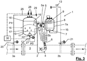
- the variant of Figure 3 offers the possibility of locally or remotely controlling the system 1 according to the invention to establish the desired pressure variation.
- the system 1 of Figure 3 incorporates a pressure transducer 27 at the outlet of the hydropneumatic tank 16.
- This pressure transducer 27 transforms a differential pressure into a normalized electric signal that allows connecting the pressure transducer 27 to a pressure control system 30 that also controls at least the set of electric valves 28 connected to the inlet of the second chamber 18 of the hydropneumatic tank 16.
- This control system 30 is provided with means for remotely connecting to a network operator, which selects a determined set point pressure P1. Starting from this target pressure value P1, the control system 30 will control the set of electric valves 28 and will compare the instantaneous pressure value at the outlet of the first chamber 17 of the hydropneumatic tank 16, obtained by means of the pressure transducer 27, with the target value P1 in time real until they match.
- the system 1 of the invention incorporates means for reading the pressure in different parts of the system, such as pressure manometers, for example, in the connections with the pipes 3 at points 3a and 3b, in the hydrostatic tank 16, or, where appropriate, in the gas cylinder 24, and in the tank 7.
- pressure manometers for example, in the connections with the pipes 3 at points 3a and 3b, in the hydrostatic tank 16, or, where appropriate, in the gas cylinder 24, and in the tank 7.
- system 1 means for generating electric power from the flow of the current circulating through the pipe 3.
- system 1 can incorporate a hydraulic turbine installed inside the pipe 3, the generated electric power of which would power the electric valves 13, 13' and, where appropriate, the control system 30.
- the invention contemplates providing a support body with means for the firm fixing thereof to the body of a valve 2, such as a butterfly valve; there being attached to the support body 31 at least one double acting piston cylinder 5 that can rotate about a horizontal axis (x) in a position for mounting said support body 31 on the valve, with first and second chambers 5a, 5b connected to the outside and a rod 6 prepared for the articulated connection thereof to a mechanism; and an energy accumulator 11 accumulating energy in the form of pressurized gas 10, communicated with the first chamber 5a of the cylinder 5.
- a valve 2 such as a butterfly valve
Landscapes
- Engineering & Computer Science (AREA)
- Physics & Mathematics (AREA)
- General Engineering & Computer Science (AREA)
- Fluid Mechanics (AREA)
- General Physics & Mathematics (AREA)
- Automation & Control Theory (AREA)
- Mechanical Engineering (AREA)
- Power Engineering (AREA)
- Supply Devices, Intensifiers, Converters, And Telemotors (AREA)
- Fluid-Driven Valves (AREA)
Claims (7)
- Système (1) de régulation de pression dans un tuyau d'approvisionnement en fluides (3), qui comprend une vanne hydraulique(2) avec des moyens mécaniques(4) pour l'actionnement de celle-ci et un cylindre à piston à double effet externe (5) avec des chambres première et deuxième (5a, 5b) et une tige (6) connectée aux moyens d'actionnement mécanique de ladite vanne, le système comprenant en outre des moyens de transmission (7) pour transmettre la pression hydraulique instantanée du tuyau en un point (3b) en aval de la vanne (2) à la chambre (5b) du cylindre (5), dont la pression agit sur le piston pour déplacer la tige (6) dans le sens de fermeture de la vanne (2), caractérisé en ce que- la chambre (5a) du cylindre (5), dont la pression agit sur le piston pour déplacer la tige dans le sens d'ouverture de la vanne (2), est connectée à un accumulateur (11) d'énergie qui accumule de l'énergie sous forme de gaz (10) sous pression à une pression P0 prédéterminée, ledit accumulateur (11) d'énergie étant formé par une première chambre (17) d'un réservoir hydropneumatique(16) qui contient le gaz (10), une deuxième chambre (18) dudit réservoir hydropneumatique(16) pouvant être connectée hydrauliquement au tuyau d'approvisionnement (3) en un point (3a) en amont de la vanne (2);- le système comprenant en outre des moyens (12) pour réguler ladite pression prédéterminée P0 ;le cylindre (5) étant monté de manière articulée sur le corps de la vanne (2) et la tige (6) étant connectée de manière articulée au moyens mécaniques (4) qui actionnent la vanne (2)
- Système (1) selon la revendication 1, caractérisé en ce que le réservoir hydropneumatique (16) est un réservoir à membrane hydropneumatique (19).
- Système (1) selon l'une quelconque des revendications précédentes, caractérisé en ce que les moyens de transmission (7) pour transmettre la pression hydraulique instantanée en un point du tuyau (3) à la chambre (5b) du cylindre (5) comprennent un réservoir (7a) connecté au tuyau (3) et qui loge une cavité expansible (8) qui contient un fluide d'actionnement (9) de manière étanche par rapport à l'intérieur dudit réservoir (7a), ladite cavité expansible (8) étant connectée à la chambre (5b) du cylindre (5).
- Système (1) selon la revendication précédente, caractérisé en ce qu'il comprend une électrovanne (13) pour établir sélectivement une connexion hydraulique, au moyen de conduits respectifs (14, 15), entre ledit réservoir (7a) et le tuyau d'approvisionnement (3) en deux points (3a, 3b) différents, un desquels est situé en amont de la vanne (2) et l'autre est situé en aval de ladite vanne (2).
- Système (1) selon la revendication précédente, caractérisé en ce que la connexion entre la deuxième chambre (18) du réservoir hydropneumatique (16) et le point (3a) du tuyau (3) disposé en amont de la vanne (2) comprend une vanne réductrice (23) et une vanne à trois voies (20) disposée entre ledit point de connexion (3a) et la vanne réductrice (23), ladite deuxième chambre (18) étant connectée à la sortie de la vanne réductrice (23) et le conduit (14) pour la connexion avec le réservoir (7a) étant connecté à un port libre de la vanne à trois voies (21).
- Système (1) selon l'une quelconque des revendications 1 à 5, caractérisé en ce qu'il comprend un transducteur de pression (27) connecté à la sortie de la première chambre (17) et un ensemble d'électrovannes (28) connectées à l'entrée de la deuxième chambre (18) du réservoir hydropneumatique (16), contrôlés par un système de contrôle (30) qui peut être contrôlé à distance et avec des moyens pour comparer la valeur de la pression de gaz à la sortie de la première chambre (17), obtenue au moyen du transducteur de pression (27), avec une valeur de pression de consigne P1 en temps réel, et qui peut générer un signal de contrôle en réponse à ladite opération de comparaison adéquate pour agir sur l'ensemble d'électrovannes (28).
- Système (1) selon l'une quelconque des revendications précédentes, caractérisé en ce que le gaz (10) est de l'azote.
Applications Claiming Priority (2)
| Application Number | Priority Date | Filing Date | Title |
|---|---|---|---|
| ES201231854A ES2463915B1 (es) | 2012-11-29 | 2012-11-29 | Sistema para la regulación de presión en una tubería de suministro de un fluido |
| PCT/ES2013/070813 WO2014083225A1 (fr) | 2012-11-29 | 2013-11-25 | Système de régulation de pression dans une tubulure d'acheminement d'un fluide |
Publications (2)
| Publication Number | Publication Date |
|---|---|
| EP2927773A1 EP2927773A1 (fr) | 2015-10-07 |
| EP2927773B1 true EP2927773B1 (fr) | 2022-01-05 |
Family
ID=49876661
Family Applications (1)
| Application Number | Title | Priority Date | Filing Date |
|---|---|---|---|
| EP13811579.5A Active EP2927773B1 (fr) | 2012-11-29 | 2013-11-25 | Système de régulation de pression dans un tuyau d'approvisionnement en fluides |
Country Status (5)
| Country | Link |
|---|---|
| US (1) | US9898015B2 (fr) |
| EP (1) | EP2927773B1 (fr) |
| ES (2) | ES2463915B1 (fr) |
| PT (1) | PT2927773T (fr) |
| WO (1) | WO2014083225A1 (fr) |
Citations (4)
| Publication number | Priority date | Publication date | Assignee | Title |
|---|---|---|---|---|
| US3730214A (en) * | 1971-09-24 | 1973-05-01 | Walworth Co | Rotary valve pressure regulating system |
| US3769998A (en) * | 1971-10-07 | 1973-11-06 | Garrett Corp | Regulator and shutoff valve |
| US20050276685A1 (en) * | 2004-06-10 | 2005-12-15 | Wiggins Jimmy D | Pneumatic valve control using downstream pressure feedback and an air turbine starter incorporating the same |
| ES2349205A1 (es) * | 2007-09-17 | 2010-12-29 | Empresa Municipal De Aguas Y Saneamiento De Murcia, S.A. | Actuador hidraulico. |
Family Cites Families (20)
| Publication number | Priority date | Publication date | Assignee | Title |
|---|---|---|---|---|
| US2266871A (en) * | 1938-09-13 | 1941-12-23 | Brown Instr Co | Regulating apparatus |
| US2320886A (en) * | 1941-05-24 | 1943-06-01 | Kieley And Mueller Inc | Reducing valve |
| US2470681A (en) * | 1943-08-23 | 1949-05-17 | Sida S Martin | Flow intermitter for cased wells |
| US3223114A (en) * | 1963-03-19 | 1965-12-14 | Homer J Shafer | Automatic shut-off for pipeline |
| GB1371898A (en) | 1970-11-20 | 1974-10-30 | Normalair Garrett Ltd | Control means for fluid flow valves |
| US3997282A (en) | 1973-03-15 | 1976-12-14 | Waterous Company | Pump pressure control device |
| US4141533A (en) * | 1976-12-09 | 1979-02-27 | United Technologies Corporation | Hydraulically operated shutoff valve |
| JPS5831482B2 (ja) * | 1978-04-03 | 1983-07-06 | 株式会社神戸製鋼所 | 油圧アクチユエ−タにおけるガス圧↓−油圧変換回路 |
| US4226124A (en) * | 1979-04-02 | 1980-10-07 | Baxter Travenol Laboratories, Inc. | Pressure isolator |
| US4729224A (en) * | 1984-06-04 | 1988-03-08 | Mcateer James D | Installation, apparatus and method for actuating doors, gates and the like under extreme environmental conditions |
| US4617958A (en) * | 1985-07-25 | 1986-10-21 | Sundstrand Corporation | Control valve |
| JP3400557B2 (ja) * | 1994-08-10 | 2003-04-28 | 大阪瓦斯株式会社 | 弁駆動装置 |
| US6095184A (en) * | 1999-06-30 | 2000-08-01 | Mac Valves Inc. | Pressure regulator with integrated control valve, adjustable downstream pressure build and quick exhaust |
| US6416033B1 (en) * | 2000-06-21 | 2002-07-09 | Flowserve Management Company | Air over hydraulics actuator system |
| GB0521454D0 (en) * | 2005-10-21 | 2005-11-30 | Energy Equipment Corp | Devices, method and apparatus |
| US20080000531A1 (en) * | 2006-06-28 | 2008-01-03 | Honeywell International, Inc. | Downstream flow sensing probe |
| US8286661B2 (en) * | 2009-05-26 | 2012-10-16 | Honeywell International Inc. | Bi-directional overpressure shut-off valve |
| FR2998871B1 (fr) * | 2012-12-05 | 2015-01-30 | Airbus Operations Sas | Vanne a double niveau de regulation et dispositif de degivrage d'une entree d'air d'une nacelle d'aeronef integrant ladite vanne |
| US9110475B2 (en) * | 2013-06-13 | 2015-08-18 | Hamilton Sundstrand Corporation | Integral filter and regulator for valve |
| US9482346B2 (en) * | 2013-09-13 | 2016-11-01 | Clark Equipment Company | System and method for controlling a compressor inlet valve |
-
2012
- 2012-11-29 ES ES201231854A patent/ES2463915B1/es active Active
-
2013
- 2013-11-25 PT PT138115795T patent/PT2927773T/pt unknown
- 2013-11-25 US US14/441,935 patent/US9898015B2/en not_active Expired - Fee Related
- 2013-11-25 EP EP13811579.5A patent/EP2927773B1/fr active Active
- 2013-11-25 ES ES13811579T patent/ES2908753T3/es active Active
- 2013-11-25 WO PCT/ES2013/070813 patent/WO2014083225A1/fr not_active Ceased
Patent Citations (4)
| Publication number | Priority date | Publication date | Assignee | Title |
|---|---|---|---|---|
| US3730214A (en) * | 1971-09-24 | 1973-05-01 | Walworth Co | Rotary valve pressure regulating system |
| US3769998A (en) * | 1971-10-07 | 1973-11-06 | Garrett Corp | Regulator and shutoff valve |
| US20050276685A1 (en) * | 2004-06-10 | 2005-12-15 | Wiggins Jimmy D | Pneumatic valve control using downstream pressure feedback and an air turbine starter incorporating the same |
| ES2349205A1 (es) * | 2007-09-17 | 2010-12-29 | Empresa Municipal De Aguas Y Saneamiento De Murcia, S.A. | Actuador hidraulico. |
Also Published As
| Publication number | Publication date |
|---|---|
| ES2463915A1 (es) | 2014-05-29 |
| US20150286223A1 (en) | 2015-10-08 |
| ES2463915B1 (es) | 2015-04-15 |
| PT2927773T (pt) | 2022-03-03 |
| ES2908753T3 (es) | 2022-05-03 |
| WO2014083225A1 (fr) | 2014-06-05 |
| US9898015B2 (en) | 2018-02-20 |
| EP2927773A1 (fr) | 2015-10-07 |
Similar Documents
| Publication | Publication Date | Title |
|---|---|---|
| NO322680B1 (no) | System for a kontrollere en ventil | |
| GB0804940D0 (en) | Method and device for regulating a pressure in a hydraulic system | |
| WO2010025354A3 (fr) | Système de commande pour une machine ayant une procédure de réchauffage hydraulique | |
| GB2437306B (en) | Autonomous shut-off valve system | |
| US20110155250A1 (en) | Hydraulic actuating device for a sliding stem control valve assembly | |
| WO2007133691A3 (fr) | Systeme hydraulique de vehicule | |
| EP3052746A2 (fr) | Actionneur pour soupape | |
| EP2161450B1 (fr) | Compresseur à air à commande par coup de bélier hydraulique | |
| AU2009200337A1 (en) | Time pulse pilot for pressure regulating control valve | |
| WO2010083058A1 (fr) | Actionneur de vanne autonome pour systeme de vanne quart de tour | |
| EP2659170A1 (fr) | Dispositif hydraulique de commande destiné à un ensemble soupape de commande à tige coulissante à levier orientable | |
| WO2017093794A1 (fr) | Commande de pression à boucle fermée de servo distributeur électro hydraulique proportionnel réduisant et soulageant un circuit hydraulique | |
| CN105042141A (zh) | 活塞自力式调节阀 | |
| EP1939701A2 (fr) | Régulateur mécanique pour un système commandé hydraulique | |
| US12578020B2 (en) | Inlet controlled regulating valve | |
| US9898015B2 (en) | System for regulating pressure in a fluid supply pipe | |
| CA2483109A1 (fr) | Systeme de commande de ventilateur a pas variable | |
| CN111226065B (zh) | 双设定点压力调节系统 | |
| US10006555B2 (en) | Fluid discharge valve | |
| RU2248451C1 (ru) | Электрогидравлическая система регулирования паровой турбины | |
| CN104197079A (zh) | 一种弹簧-液压双冗余速动及伺服控制电液执行器 | |
| CN201269311Y (zh) | 一种电液伺服控制的液压调节型阀门 | |
| WO2009035231A3 (fr) | Dispositif de commande hydraulique pour soupape de turbine | |
| CN202579376U (zh) | 用于多个液压执行器控制的液压手动工作站 | |
| CN214147426U (zh) | 一种无人值守在线实时试车台供配气系统 |
Legal Events
| Date | Code | Title | Description |
|---|---|---|---|
| PUAI | Public reference made under article 153(3) epc to a published international application that has entered the european phase |
Free format text: ORIGINAL CODE: 0009012 |
|
| 17P | Request for examination filed |
Effective date: 20150625 |
|
| AK | Designated contracting states |
Kind code of ref document: A1 Designated state(s): AL AT BE BG CH CY CZ DE DK EE ES FI FR GB GR HR HU IE IS IT LI LT LU LV MC MK MT NL NO PL PT RO RS SE SI SK SM TR |
|
| AX | Request for extension of the european patent |
Extension state: BA ME |
|
| DAX | Request for extension of the european patent (deleted) | ||
| STAA | Information on the status of an ep patent application or granted ep patent |
Free format text: STATUS: EXAMINATION IS IN PROGRESS |
|
| 17Q | First examination report despatched |
Effective date: 20181029 |
|
| GRAP | Despatch of communication of intention to grant a patent |
Free format text: ORIGINAL CODE: EPIDOSNIGR1 |
|
| STAA | Information on the status of an ep patent application or granted ep patent |
Free format text: STATUS: GRANT OF PATENT IS INTENDED |
|
| INTG | Intention to grant announced |
Effective date: 20210705 |
|
| GRAS | Grant fee paid |
Free format text: ORIGINAL CODE: EPIDOSNIGR3 |
|
| GRAA | (expected) grant |
Free format text: ORIGINAL CODE: 0009210 |
|
| STAA | Information on the status of an ep patent application or granted ep patent |
Free format text: STATUS: THE PATENT HAS BEEN GRANTED |
|
| AK | Designated contracting states |
Kind code of ref document: B1 Designated state(s): AL AT BE BG CH CY CZ DE DK EE ES FI FR GB GR HR HU IE IS IT LI LT LU LV MC MK MT NL NO PL PT RO RS SE SI SK SM TR |
|
| REG | Reference to a national code |
Ref country code: GB Ref legal event code: FG4D |
|
| REG | Reference to a national code |
Ref country code: CH Ref legal event code: EP |
|
| REG | Reference to a national code |
Ref country code: AT Ref legal event code: REF Ref document number: 1461150 Country of ref document: AT Kind code of ref document: T Effective date: 20220115 |
|
| REG | Reference to a national code |
Ref country code: DE Ref legal event code: R096 Ref document number: 602013080610 Country of ref document: DE |
|
| REG | Reference to a national code |
Ref country code: IE Ref legal event code: FG4D |
|
| REG | Reference to a national code |
Ref country code: PT Ref legal event code: SC4A Ref document number: 2927773 Country of ref document: PT Date of ref document: 20220303 Kind code of ref document: T Free format text: AVAILABILITY OF NATIONAL TRANSLATION Effective date: 20220225 |
|
| REG | Reference to a national code |
Ref country code: LT Ref legal event code: MG9D |
|
| REG | Reference to a national code |
Ref country code: ES Ref legal event code: FG2A Ref document number: 2908753 Country of ref document: ES Kind code of ref document: T3 Effective date: 20220503 |
|
| REG | Reference to a national code |
Ref country code: NL Ref legal event code: MP Effective date: 20220105 |
|
| REG | Reference to a national code |
Ref country code: AT Ref legal event code: MK05 Ref document number: 1461150 Country of ref document: AT Kind code of ref document: T Effective date: 20220105 |
|
| PG25 | Lapsed in a contracting state [announced via postgrant information from national office to epo] |
Ref country code: NL Free format text: LAPSE BECAUSE OF FAILURE TO SUBMIT A TRANSLATION OF THE DESCRIPTION OR TO PAY THE FEE WITHIN THE PRESCRIBED TIME-LIMIT Effective date: 20220105 |
|
| PG25 | Lapsed in a contracting state [announced via postgrant information from national office to epo] |
Ref country code: SE Free format text: LAPSE BECAUSE OF FAILURE TO SUBMIT A TRANSLATION OF THE DESCRIPTION OR TO PAY THE FEE WITHIN THE PRESCRIBED TIME-LIMIT Effective date: 20220105 Ref country code: RS Free format text: LAPSE BECAUSE OF FAILURE TO SUBMIT A TRANSLATION OF THE DESCRIPTION OR TO PAY THE FEE WITHIN THE PRESCRIBED TIME-LIMIT Effective date: 20220105 Ref country code: NO Free format text: LAPSE BECAUSE OF FAILURE TO SUBMIT A TRANSLATION OF THE DESCRIPTION OR TO PAY THE FEE WITHIN THE PRESCRIBED TIME-LIMIT Effective date: 20220405 Ref country code: LT Free format text: LAPSE BECAUSE OF FAILURE TO SUBMIT A TRANSLATION OF THE DESCRIPTION OR TO PAY THE FEE WITHIN THE PRESCRIBED TIME-LIMIT Effective date: 20220105 Ref country code: HR Free format text: LAPSE BECAUSE OF FAILURE TO SUBMIT A TRANSLATION OF THE DESCRIPTION OR TO PAY THE FEE WITHIN THE PRESCRIBED TIME-LIMIT Effective date: 20220105 Ref country code: BG Free format text: LAPSE BECAUSE OF FAILURE TO SUBMIT A TRANSLATION OF THE DESCRIPTION OR TO PAY THE FEE WITHIN THE PRESCRIBED TIME-LIMIT Effective date: 20220405 |
|
| PG25 | Lapsed in a contracting state [announced via postgrant information from national office to epo] |
Ref country code: PL Free format text: LAPSE BECAUSE OF FAILURE TO SUBMIT A TRANSLATION OF THE DESCRIPTION OR TO PAY THE FEE WITHIN THE PRESCRIBED TIME-LIMIT Effective date: 20220105 Ref country code: LV Free format text: LAPSE BECAUSE OF FAILURE TO SUBMIT A TRANSLATION OF THE DESCRIPTION OR TO PAY THE FEE WITHIN THE PRESCRIBED TIME-LIMIT Effective date: 20220105 Ref country code: GR Free format text: LAPSE BECAUSE OF FAILURE TO SUBMIT A TRANSLATION OF THE DESCRIPTION OR TO PAY THE FEE WITHIN THE PRESCRIBED TIME-LIMIT Effective date: 20220406 Ref country code: FI Free format text: LAPSE BECAUSE OF FAILURE TO SUBMIT A TRANSLATION OF THE DESCRIPTION OR TO PAY THE FEE WITHIN THE PRESCRIBED TIME-LIMIT Effective date: 20220105 Ref country code: AT Free format text: LAPSE BECAUSE OF FAILURE TO SUBMIT A TRANSLATION OF THE DESCRIPTION OR TO PAY THE FEE WITHIN THE PRESCRIBED TIME-LIMIT Effective date: 20220105 |
|
| PG25 | Lapsed in a contracting state [announced via postgrant information from national office to epo] |
Ref country code: IS Free format text: LAPSE BECAUSE OF FAILURE TO SUBMIT A TRANSLATION OF THE DESCRIPTION OR TO PAY THE FEE WITHIN THE PRESCRIBED TIME-LIMIT Effective date: 20220505 |
|
| REG | Reference to a national code |
Ref country code: DE Ref legal event code: R097 Ref document number: 602013080610 Country of ref document: DE |
|
| PG25 | Lapsed in a contracting state [announced via postgrant information from national office to epo] |
Ref country code: SM Free format text: LAPSE BECAUSE OF FAILURE TO SUBMIT A TRANSLATION OF THE DESCRIPTION OR TO PAY THE FEE WITHIN THE PRESCRIBED TIME-LIMIT Effective date: 20220105 Ref country code: SK Free format text: LAPSE BECAUSE OF FAILURE TO SUBMIT A TRANSLATION OF THE DESCRIPTION OR TO PAY THE FEE WITHIN THE PRESCRIBED TIME-LIMIT Effective date: 20220105 Ref country code: RO Free format text: LAPSE BECAUSE OF FAILURE TO SUBMIT A TRANSLATION OF THE DESCRIPTION OR TO PAY THE FEE WITHIN THE PRESCRIBED TIME-LIMIT Effective date: 20220105 Ref country code: EE Free format text: LAPSE BECAUSE OF FAILURE TO SUBMIT A TRANSLATION OF THE DESCRIPTION OR TO PAY THE FEE WITHIN THE PRESCRIBED TIME-LIMIT Effective date: 20220105 Ref country code: DK Free format text: LAPSE BECAUSE OF FAILURE TO SUBMIT A TRANSLATION OF THE DESCRIPTION OR TO PAY THE FEE WITHIN THE PRESCRIBED TIME-LIMIT Effective date: 20220105 Ref country code: CZ Free format text: LAPSE BECAUSE OF FAILURE TO SUBMIT A TRANSLATION OF THE DESCRIPTION OR TO PAY THE FEE WITHIN THE PRESCRIBED TIME-LIMIT Effective date: 20220105 |
|
| PLBE | No opposition filed within time limit |
Free format text: ORIGINAL CODE: 0009261 |
|
| STAA | Information on the status of an ep patent application or granted ep patent |
Free format text: STATUS: NO OPPOSITION FILED WITHIN TIME LIMIT |
|
| PG25 | Lapsed in a contracting state [announced via postgrant information from national office to epo] |
Ref country code: AL Free format text: LAPSE BECAUSE OF FAILURE TO SUBMIT A TRANSLATION OF THE DESCRIPTION OR TO PAY THE FEE WITHIN THE PRESCRIBED TIME-LIMIT Effective date: 20220105 |
|
| 26N | No opposition filed |
Effective date: 20221006 |
|
| PGFP | Annual fee paid to national office [announced via postgrant information from national office to epo] |
Ref country code: PT Payment date: 20221110 Year of fee payment: 10 Ref country code: IT Payment date: 20221117 Year of fee payment: 10 |
|
| PG25 | Lapsed in a contracting state [announced via postgrant information from national office to epo] |
Ref country code: SI Free format text: LAPSE BECAUSE OF FAILURE TO SUBMIT A TRANSLATION OF THE DESCRIPTION OR TO PAY THE FEE WITHIN THE PRESCRIBED TIME-LIMIT Effective date: 20220105 |
|
| REG | Reference to a national code |
Ref country code: DE Ref legal event code: R119 Ref document number: 602013080610 Country of ref document: DE |
|
| PG25 | Lapsed in a contracting state [announced via postgrant information from national office to epo] |
Ref country code: MC Free format text: LAPSE BECAUSE OF FAILURE TO SUBMIT A TRANSLATION OF THE DESCRIPTION OR TO PAY THE FEE WITHIN THE PRESCRIBED TIME-LIMIT Effective date: 20220105 |
|
| REG | Reference to a national code |
Ref country code: CH Ref legal event code: PL |
|
| GBPC | Gb: european patent ceased through non-payment of renewal fee |
Effective date: 20221125 |
|
| REG | Reference to a national code |
Ref country code: BE Ref legal event code: MM Effective date: 20221130 |
|
| PG25 | Lapsed in a contracting state [announced via postgrant information from national office to epo] |
Ref country code: LI Free format text: LAPSE BECAUSE OF NON-PAYMENT OF DUE FEES Effective date: 20221130 Ref country code: CH Free format text: LAPSE BECAUSE OF NON-PAYMENT OF DUE FEES Effective date: 20221130 |
|
| P01 | Opt-out of the competence of the unified patent court (upc) registered |
Effective date: 20230711 |
|
| PG25 | Lapsed in a contracting state [announced via postgrant information from national office to epo] |
Ref country code: LU Free format text: LAPSE BECAUSE OF NON-PAYMENT OF DUE FEES Effective date: 20221125 |
|
| PG25 | Lapsed in a contracting state [announced via postgrant information from national office to epo] |
Ref country code: IE Free format text: LAPSE BECAUSE OF NON-PAYMENT OF DUE FEES Effective date: 20221125 Ref country code: GB Free format text: LAPSE BECAUSE OF NON-PAYMENT OF DUE FEES Effective date: 20221125 Ref country code: DE Free format text: LAPSE BECAUSE OF NON-PAYMENT OF DUE FEES Effective date: 20230601 |
|
| PG25 | Lapsed in a contracting state [announced via postgrant information from national office to epo] |
Ref country code: BE Free format text: LAPSE BECAUSE OF NON-PAYMENT OF DUE FEES Effective date: 20221130 |
|
| PG25 | Lapsed in a contracting state [announced via postgrant information from national office to epo] |
Ref country code: HU Free format text: LAPSE BECAUSE OF FAILURE TO SUBMIT A TRANSLATION OF THE DESCRIPTION OR TO PAY THE FEE WITHIN THE PRESCRIBED TIME-LIMIT; INVALID AB INITIO Effective date: 20131125 |
|
| PG25 | Lapsed in a contracting state [announced via postgrant information from national office to epo] |
Ref country code: CY Free format text: LAPSE BECAUSE OF FAILURE TO SUBMIT A TRANSLATION OF THE DESCRIPTION OR TO PAY THE FEE WITHIN THE PRESCRIBED TIME-LIMIT Effective date: 20220105 |
|
| PG25 | Lapsed in a contracting state [announced via postgrant information from national office to epo] |
Ref country code: MK Free format text: LAPSE BECAUSE OF FAILURE TO SUBMIT A TRANSLATION OF THE DESCRIPTION OR TO PAY THE FEE WITHIN THE PRESCRIBED TIME-LIMIT Effective date: 20220105 |
|
| PG25 | Lapsed in a contracting state [announced via postgrant information from national office to epo] |
Ref country code: PT Free format text: LAPSE BECAUSE OF NON-PAYMENT OF DUE FEES Effective date: 20240527 |
|
| PG25 | Lapsed in a contracting state [announced via postgrant information from national office to epo] |
Ref country code: PT Free format text: LAPSE BECAUSE OF NON-PAYMENT OF DUE FEES Effective date: 20240527 |
|
| PG25 | Lapsed in a contracting state [announced via postgrant information from national office to epo] |
Ref country code: MT Free format text: LAPSE BECAUSE OF FAILURE TO SUBMIT A TRANSLATION OF THE DESCRIPTION OR TO PAY THE FEE WITHIN THE PRESCRIBED TIME-LIMIT Effective date: 20220105 |
|
| PG25 | Lapsed in a contracting state [announced via postgrant information from national office to epo] |
Ref country code: IT Free format text: LAPSE BECAUSE OF NON-PAYMENT OF DUE FEES Effective date: 20231125 |
|
| PG25 | Lapsed in a contracting state [announced via postgrant information from national office to epo] |
Ref country code: IT Free format text: LAPSE BECAUSE OF NON-PAYMENT OF DUE FEES Effective date: 20231125 |
|
| REG | Reference to a national code |
Ref country code: ES Ref legal event code: PC2A Owner name: AQUATEC SOLUCIONES MEDIOAMBIENTALES, S.A.U. Effective date: 20250523 |
|
| PG25 | Lapsed in a contracting state [announced via postgrant information from national office to epo] |
Ref country code: TR Free format text: LAPSE BECAUSE OF FAILURE TO SUBMIT A TRANSLATION OF THE DESCRIPTION OR TO PAY THE FEE WITHIN THE PRESCRIBED TIME-LIMIT Effective date: 20220105 |
|
| PGFP | Annual fee paid to national office [announced via postgrant information from national office to epo] |
Ref country code: FR Payment date: 20251121 Year of fee payment: 13 |
|
| PGFP | Annual fee paid to national office [announced via postgrant information from national office to epo] |
Ref country code: ES Payment date: 20251202 Year of fee payment: 13 |