EP2927931A1 - Lampe à décharge et outil d'éclairage pour véhicule - Google Patents
Lampe à décharge et outil d'éclairage pour véhicule Download PDFInfo
- Publication number
- EP2927931A1 EP2927931A1 EP13859065.8A EP13859065A EP2927931A1 EP 2927931 A1 EP2927931 A1 EP 2927931A1 EP 13859065 A EP13859065 A EP 13859065A EP 2927931 A1 EP2927931 A1 EP 2927931A1
- Authority
- EP
- European Patent Office
- Prior art keywords
- halide
- discharge lamp
- electrodes
- indium
- discharge
- Prior art date
- Legal status (The legal status is an assumption and is not a legal conclusion. Google has not performed a legal analysis and makes no representation as to the accuracy of the status listed.)
- Granted
Links
Images


Classifications
-
- H—ELECTRICITY
- H01—ELECTRIC ELEMENTS
- H01J—ELECTRIC DISCHARGE TUBES OR DISCHARGE LAMPS
- H01J61/00—Gas-discharge or vapour-discharge lamps
- H01J61/82—Lamps with high-pressure unconstricted discharge having a cold pressure > 400 Torr
- H01J61/827—Metal halide arc lamps
-
- H—ELECTRICITY
- H01—ELECTRIC ELEMENTS
- H01J—ELECTRIC DISCHARGE TUBES OR DISCHARGE LAMPS
- H01J61/00—Gas-discharge or vapour-discharge lamps
- H01J61/84—Lamps with discharge constricted by high pressure
- H01J61/88—Lamps with discharge constricted by high pressure with discharge additionally constricted by envelope
-
- F—MECHANICAL ENGINEERING; LIGHTING; HEATING; WEAPONS; BLASTING
- F21—LIGHTING
- F21S—NON-PORTABLE LIGHTING DEVICES; SYSTEMS THEREOF; VEHICLE LIGHTING DEVICES SPECIALLY ADAPTED FOR VEHICLE EXTERIORS
- F21S41/00—Illuminating devices specially adapted for vehicle exteriors, e.g. headlamps
- F21S41/10—Illuminating devices specially adapted for vehicle exteriors, e.g. headlamps characterised by the light source
- F21S41/14—Illuminating devices specially adapted for vehicle exteriors, e.g. headlamps characterised by the light source characterised by the type of light source
- F21S41/17—Discharge light sources
- F21S41/172—High-intensity discharge light sources
-
- F—MECHANICAL ENGINEERING; LIGHTING; HEATING; WEAPONS; BLASTING
- F21—LIGHTING
- F21S—NON-PORTABLE LIGHTING DEVICES; SYSTEMS THEREOF; VEHICLE LIGHTING DEVICES SPECIALLY ADAPTED FOR VEHICLE EXTERIORS
- F21S43/00—Signalling devices specially adapted for vehicle exteriors, e.g. brake lamps, direction indicator lights or reversing lights
-
- H—ELECTRICITY
- H01—ELECTRIC ELEMENTS
- H01J—ELECTRIC DISCHARGE TUBES OR DISCHARGE LAMPS
- H01J61/00—Gas-discharge or vapour-discharge lamps
- H01J61/02—Details
- H01J61/12—Selection of substances for gas fillings; Specified operating pressure or temperature
- H01J61/125—Selection of substances for gas fillings; Specified operating pressure or temperature having an halogenide as principal component
-
- H—ELECTRICITY
- H01—ELECTRIC ELEMENTS
- H01J—ELECTRIC DISCHARGE TUBES OR DISCHARGE LAMPS
- H01J61/00—Gas-discharge or vapour-discharge lamps
- H01J61/02—Details
- H01J61/30—Vessels; Containers
-
- F—MECHANICAL ENGINEERING; LIGHTING; HEATING; WEAPONS; BLASTING
- F21—LIGHTING
- F21W—INDEXING SCHEME ASSOCIATED WITH SUBCLASSES F21K, F21L, F21S and F21V, RELATING TO USES OR APPLICATIONS OF LIGHTING DEVICES OR SYSTEMS
- F21W2102/00—Exterior vehicle lighting devices for illuminating purposes
-
- F—MECHANICAL ENGINEERING; LIGHTING; HEATING; WEAPONS; BLASTING
- F21—LIGHTING
- F21Y—INDEXING SCHEME ASSOCIATED WITH SUBCLASSES F21K, F21L, F21S and F21V, RELATING TO THE FORM OR THE KIND OF THE LIGHT SOURCES OR OF THE COLOUR OF THE LIGHT EMITTED
- F21Y2101/00—Point-like light sources
Definitions
- Embodiments described below generally relate to a discharge lamp and a vehicular lighting fixture.
- Patent Literature 1 JP-A-2004-172056
- a problem to be solved by the present invention is to provide a discharge lamp and a vehicular lighting fixture that can suppress an increase in a tube voltage during a product life cycle.
- a discharge lamp includes: a light emitting section including, on the inside, a discharge space in which metal halide including halide of indium is encapsulated; and a pair of electrodes projecting to the inside of the discharge space and disposed to be opposed a predetermined distance apart from each other.
- a percentage of the halide of indium included in the metal halide is 0.1 wt% or higher and 0.33 wt% or lower.
- a dimension "d" of a longest portion of the discharge space in a direction orthogonal to an extending direction of the pair of electrodes in the discharge space is 1.5 mm or more and 2.3 mm or less.
- a first invention is a discharge lamp including: a light emitting section including, on the inside, a discharge space in which metal halide including halide of indium is encapsulated; and a pair of electrodes projecting to the inside of the discharge space and disposed to be opposed a predetermined distance apart from each other, wherein a percentage of the halide of indium included in the metal halide is 0.1 wt% or higher and 0.33 wt% or lower, and a dimension "d" of a longest portion of the discharge space in a direction orthogonal to an extending direction of the pair of electrodes in the discharge space is 1.5 mm or more and 2.3 mm or less.
- a second invention is the discharge lamp in the first invention, further including sealing sections respectively provided at both end portions of the light emitting section in the extending direction of the pair of electrodes, wherein gaps are provided between the sealing sections and the electrodes.
- a third invention is the discharge lamp in the first or second embodiment, wherein the halide of indium accumulates in the gaps when lighting and extinction of the discharge lamp are performed.
- a fourth invention is a vehicular lighting fixture including: the discharge lamp described in any one of the above-mentioned inventions; and a lighting circuit electrically connected to the discharge lamp.
- a fifth invention is the vehicular lighting fixture in the fourth invention, wherein the discharge lamp is attached to horizontally set the pair of electrodes provided in the discharge lamp.
- a discharge lamp according to an embodiment of the present invention can be, for example, an HID (High Intensity Discharge) lamp used in a headlight of an automobile.
- the discharge lamp can be a discharge lamp that performs so-called horizontal lighting.
- the discharge lamp according to the embodiment of the present invention is not limited to the headlight of the automobile.
- the discharge lamp is the HID lamp used in the headlight of the automobile.
- Fig. 1 is a schematic diagram for illustrating a discharge lamp 100 according to a first embodiment.
- a forward direction is referred to as a front end side
- the opposite direction of the forward direction is referred to as a rear end side
- an upward direction is referred to as an upper end side
- a downward direction is referred to as a lower end side.
- a burner 101 and a socket 102 are provided in the discharge lamp 100.
- an inner tube 1, an outer tube 5, a light emitting section 11, sealing sections 12, electrode mounts 3, a support wire 35, a sleeve 4, and a metal band 71 are provided.
- the inner tube 1 assumes a cylindrical shape and is formed of a material having translucency and heat resistance.
- the inner tube 1 can be formed of, for example, quartz glass.
- the outer tube 5 is provided on the outer side of the inner tube 1 concentrically with the inner tube 1. That is, the inner tube 1 and the outer tube 5 form a double tube structure.
- the outer tube 5 and the inner tube 1 can be connected by welding the outer tube 5 to the vicinity of a cylindrical section 14 of the inner tube 1.
- Gas is encapsulated in a closed space formed between the inner tube 1 and the outer tube 5.
- the encapsulated gas can be dielectric barrier dischargeable gas, for example, one kind of gas selected from neon, argon, xenon, and nitrogen or mixed gas of these gases.
- Encapsulating pressure of the gas is preferably set to 0.3 atm or lower, in particular, 0.1 atm or lower at normal temperate (25°C).
- the outer tube 5 is preferably formed of a material having a coefficient of thermal expansion close to the coefficient of thermal expansion of the material of the inner tube 1 and having an ultraviolet blocking property.
- the outer tube 5 can be formed of quartz glass added with oxide of, for example, titanium, cerium, or aluminum.
- the light emitting section 11 assumes an elliptical shape as a cross sectional shape and is provided near the center of the inner tube 1. On the inside of the light emitting section 11, a discharge space 111 formed in substantially a columnar shape in the center portion and narrowed in a taper shape at both the ends is provided.
- a dimension "d" of a longest portion of the discharge space 111 in a direction orthogonal to an extending direction of a pair of electrodes 32 in the discharge space 111 is preferably set to 1.5 mm or more and 2.3 mm or less.
- the dimension "d" of the longest portion of the inner diameter of the light emitting section 11 is, for example, the dimension between inner walls 11a of the center portion (when the center portion is columnar, the diameter dimension).
- a discharge medium is encapsulated in the discharge space 111.
- the discharge medium contains metal halide 2 and inert gas.
- the light emitting section 11 includes, on the inside, the discharge space 111 in which the metal halide 2 including halide of indium is encapsulated.
- the metal halide 2 includes halide of indium, halide of sodium, halide of scandium, and halide of zinc.
- halogen include iodine.
- bromine, chloride, and the like can also be used instead of iodine.
- the percentage of the halide of indium included in the metal halide 2 is a percentage in an initial state (e.g., an unused discharge lamp 100). As explained below, when lighting and extinction of the discharge lamp 100 are repeated, the percentage of the halide of indium included in the metal halide 2 gradually decreases.
- the inert gas encapsulated in the discharge space 111 can be, for example, xenon.
- Encapsulating pressure of the inert gas can be adjusted according to a purpose. For example, in order to increase a total luminous flux, it is preferable to set the encapsulating pressure to 10 atm or higher and 20 atm or lower at the normal temperature (25°C).
- xenon, neon, argon, krypton, and the like can be used or mixed gas of these gases can also be used.
- the sealing sections 12 assume a tabular shape and are provided at both the ends of the light emitting section 11. That is, the sealing sections 12 assume the tabular shape and are respectively provided at both the end portions in the extending direction of the pair of electrodes 32 of the light emitting section 11.
- the sealing sections 12 can be formed using, for example, a pinch seal method. Note that the sealing sections 12 may be formed by a shrink seal method and assume a columnar shape.
- the cylindrical section 14 is continuously formed via a boundary section 13.
- the electrode mounts 3 are provided on the inside of the sealing sections 12.
- metal foils 31, electrodes 32, coils 33, and lead wires 34 are provided.
- the metal foils 31 assume a thin plate shape and are formed of, for example, molybdenum.
- the electrodes 32 assume a columnar shape and are formed of, for example, so-called thoriated tungsten obtained by doping thorium oxide in tungsten. Note that the material of the electrodes 32 may be pure tungsten, doped tungsten, rhenium tungsten, or the like.
- One ends of the electrodes 32 are welded to end portions of the metal foils 31 on the light emitting section 11 sides.
- the other ends of the electrodes 32 project into the discharge space 111.
- the electrodes 32 are disposed such that the distal ends of the electrodes 32 are opposed to each other while keeping a predetermined distance.
- the pair of electrodes 32 projects to the inside of the discharge space 111 and is disposed to be opposed a predetermined distance apart from each other.
- the distance between the distal ends of the electrodes 32 can be set to, for example, 3.4 mm or more and 4.4 mm or less.
- the shape of the electrodes 32 does not have to be a columnar shape having a fixed diameter in a tube axis direction.
- the shape of the electrodes 32 may be a non-columnar shape, the diameter of the distal end portion of which is set larger than the diameter of the proximal end portion thereof, may be a spherical body at the distal end, or may be a shape, one electrode diameter and the other electrode diameter of which are different as in a direct-current lighting type.
- the coils 33 can be formed of, for example, a metal wire made of doped tungsten.
- the coils 33 are wound on the outer sides of the electrodes 32 provided on the insides of the sealing sections 12.
- the wire diameter of the coils 33 can be set to about 30 ⁇ m to 100 ⁇ m and the coil pitch of the coils 33 can be set to 600% or less.
- the lead wires 34 can be, for example, metal wires made of molybdenum. One ends of the lead wires 34 are placed at end portions of the metal foils 31 on the opposite sides of the light emitting section 11 sides. The other ends of the lead wires 34 extend to the outside of the inner tube 1.
- the support wire 35 assumes an L shape and is connected to an end portion of the lead wire 34 drawn out from the front end side of the discharge lamp 100.
- the support wire 35 and the lead wire 34 can be connected by laser welding.
- the support wire 35 can be formed of, for example, nickel.
- the sleeve 4 covers a portion of the support wire 35 extending in parallel to the inner tube 1.
- the sleeve 4 can be a sleeve that assumes, for example, a cylindrical shape and is formed of ceramic.
- the metal band 71 is fixed to the outer circumferential surface on the rear end side of the outer tube 5.
- a main body section 6 In the socket 102, a main body section 6, a metal fitting 72, a bottom terminal 81, and a side terminal 82 are provided.
- the main body section 6 is formed of an insulative material such as resin. On the inside of the main body section 6, the lead wire 34, the support wire 35, and the rear end side of the sleeve 4 are provided.
- the metal fitting 72 is provided at an end portion on the front end side of the main body section 6.
- the metal fitting 72 projects from the main body section 6 and retains the metal band 71. Since the metal band 71 is retained by the metal fitting 72, the burner 101 is retained by the socket 102.
- the bottom terminal 81 is provided on the inside on the rear end portion side of the main body section 6.
- the bottom terminal 81 is formed of a conductive material and electrically connected to the lead wire 34.
- the side terminal 82 is provided on a sidewall on the rear end portion side of the main body section 6.
- the side terminal 82 is formed of a conductive material and electrically connected to the support wire 35.
- the discharge lamp 100 is connected to a lighting circuit 205 (see Fig. 7 ) such that the bottom terminal 81 is on a high voltage side and the side terminal 82 is on a low voltage side.
- the discharge lamp 100 is attached in a state in which the center axis of the discharge lamp 100 is in a substantially horizontal state and such that the support wire 35 is located substantially on the lower end side (in a lower part). Lighting of the discharge lamp 100 attached in such a direction is referred to as horizontal lighting.
- the temperature of the light emitting section 11 rises.
- an amount of evaporation of the metal halide 2 increases.
- the halide of sodium, the halide of scandium, and the halide of zinc evaporate and contribute to a tube voltage.
- the discharge lamp 100 used in the headlight of the automobile or the like is controlled by a ballast circuit explained below or the like such that rated electric power is substantially fixed. Therefore, when the tube voltage rises, since an electric current decreases and electric discharge is suppressed, the rise in the tube voltage is likely to lead to lighting failure.
- the use time of the discharge lamp 100 increases, blackening and clouding (loss of clarity) of the light emitting section 11 gradually worsen.
- blackening and the clouding of the light emitting section 11 worsen, since light that should be radiated to the outside of the light emitting section 11 is blocked, heat is generated in the light emitting section 11. Therefore, if the use time of the discharge lamp 100 increases, the temperature of the light emitting section 11 tends to rise. The tube voltage tends to be high from the start of the lighting.
- the tube voltage tends to rise because of various causes. It is preferable to keep the tube voltage within a predetermined range (e.g., 40 V or higher) at the start of the lighting of the discharge lamp 100.
- the percentage of the halide of indium included in the metal halide 2 is set to 0.1 wt% or higher and 0.33 wt% or lower and the dimension "d" of the longest portion of the inner diameter of the light emitting section 11 is set to 1.5 mm or more and 2.3 mm or less.
- Gaps connected to the discharge space 111 are provided between the electrodes 32 and the sealing sections 12.
- Fig. 2 is a graph illustrating a relation between percentages of the halide of indium and changes in the tube voltage.
- Fig. 2 is a result obtained by performing a flashing test under a condition same as an EU 120 minute mode, which is a life test condition for an automobile headlight discharge lamp determined by the Japan Electric Lamp Manufacturers Association.
- the dimension "d" of the longest portion of the inner diameter of the light emitting section 11 was set to 2.2 mm, the outer diameter dimension of the light emitting section 11 was set to 5.2 mm, and the length in the longitudinal direction of the light emitting section 11 was set to 7.8 mm.
- the electrodes 32 assumed a columnar shape.
- the diameter dimension of the electrodes 32 was set to 0.28 mm and the length dimension of the electrodes 32 was set to 7.5 mm.
- the projection length of the electrodes 32 into the discharge space 111 was set to 2.2 mm.
- the outer tube 5 was made of UV cut quartz glass.
- Argon (Ar) which was inert gas, was encapsulated in a closed space formed between the inner tube 1 and the outer tube 5. Encapsulating pressure of the inert gas was set to 0.1 atm at the normal temperature (25°C).
- An amount of the metal halide 2 including the halide of indium was set to 0.2 mg. Note that the halide was iodide.
- the percentage of the halide of indium included in the metal halide 2 was set to 0.05 wt%, 0.10 wt%, and 0.15 wt%.
- A is 0.05 wt%
- B is 0.10 wt%
- C is 0.15 wt%.
- Electric power was controlled using a stabilizer (an electrical ballast) to be 60 W at the start of lighting and 25 W during stable lighting.
- the discharge lamp 100 was flashed at a flashing cycle of the EU 120 minute mode and a change in the tube voltage was measured.
- the percentage of the halide of indium included in the metal halide 2 is set to 0.1 wt% or higher, it is possible to suppress a rise in the tube voltage.
- the tube voltage changes.
- a reason for the change in the tube voltage is not always clear, for example, reasons explained below are conceivable.
- the discharge lamp 100 is lit, plasma is generated in the discharge space 111.
- the plasma is unevenly present on the upper end side of the discharge space 111 because of a convection current. Therefore, the temperature on the upper end side of the light emitting section 11 is higher than the temperature on the lower end side of the light emitting section 11.
- the temperature of the electrodes 32 close to the plasma and made of a material having high thermal conductivity is higher than the temperature of the light emitting section 11.
- the speed of the drop of the temperature is different in the electrodes 32 and on the lower end side of the discharge space 111 in which the condensed halide of indium accumulates. That is, the speed of the temperature drop of the electrodes 32 made of the material having high thermal conductivity is higher than the speed of the temperature drop on the lower end side of the discharge space 111.
- Fig. 3 is a schematic graph for illustrating states of temperature drops.
- S1 represents the temperature drop of the electrodes 32 and S2 to S4 represent the temperature drops on the lower end side of the discharge space 111 in which the condensed halide of indium accumulates.
- S2 and S3 are temperature curves of the temperature on the lower side of the discharge space 111 that drops when the discharge lamp 100 during a life cycle is extinguished.
- S4 is a temperature curve on the lower side of the discharge space 111 at an initial stage of the life cycle.
- the temperature drop is caused by the extinction of the discharge lamp 100.
- the condensation starts when the temperature drops below the condensation temperature of the evaporated halide of indium. In this case, the condensation preferentially occurs in a place where the temperature is low.
- the temperature of S4 remains lower than the temperature of S1. Therefore, the condensation preferentially occurs on the lower end side of the discharge space 111.
- the condensed halide of indium intrudes into the gaps between the electrodes 32 and the sealing sections 12.
- the halide of indium intruding into the gaps between the electrodes 32 and the sealing sections 12 are suppressed from evaporating again when the discharge lamp 100 is lit thereafter.
- the halide of indium gradually accumulates in the gaps between the electrodes 32 and the sealing sections 12. Therefore, an amount of the halide of indium included in the metal halide 2 gradually decreases.
- the amount of the halide of indium decreases, the amount of the evaporated halide of indium present in the discharge space 111 during the lighting decreases.
- the percentage of the halide of indium included in the metal halide 2 is set to 0.1 wt% or higher, it is possible to suppress the rise in the tube voltage.
- the percentage of the halide of indium included in the metal halide 2 is increased, a problem occurs in that the luminous flux decreases because the influence of intrusion of the indium during the life cycle is too large.
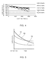
- Fig. 4 is a graph for illustrating a relation between percentages of the halide of indium and decreases in the luminous flux.
- the percentage of the halide of indium included in the metal halide 2 is set to 0.50 wt%, the decrease in the luminous flux is too large.
- the percentage of the halide of indium included in the metal halide 2 is set to 0.1 wt% or higher and 0.33 wt% or lower.
- Fig. 5 is a schematic graph for illustrating states of temperature drops.
- S1 represents a temperature drop of the electrodes 32 and S5 and S6 represent temperature drops on the lower end side of the discharge space 111 in which the condensed halide of indium accumulates.
- the dimension "d" in S5 is smaller than the dimension "d” in S6.
- the dimension "d" is small, the distance to the plasma is small. Therefore, the temperature on the lower end side of the discharge space 111 during the lighting is high.
- temperature immediately after the extinction in S5 is higher than temperature immediate after the extinction in S6.
- the temperature of S6 remains lower than the temperature of S1. Therefore, the condensation preferentially occurs on the lower end side of the discharge space 111.
- the amount of the halide of indium included in the metal halide 2 is substantially fixed.
- Table 1 is a table for illustrating a proper range of the dimension "d" of the longest portion of the inner diameter of the light emitting section 11.
- Table 1 Dimension d (mm) Percentage of halide of indium Presence or absence of suppression effect of tube voltage 2.4 0.34 No 2.4 0.15 No 2.4 0.10 No 2.3 0.34 Yes 2.3 0.15 Yes 2.3 0.10 Yes 2.2 0.34 Yes 2.2 0.15 Yes 2.2 0.10 Yes 1.5 0.34 Yes 1.5 0.15 Yes 1.5 0.10 Yes 1.2 0.34 Lighting failure due to leak occurrence at 500 h 1.2 0.15 Lighting failure due to leak occurrence at 500 h 1.2 0.10 Leak occurrence at 500 h As it is seen from Table 1, if the dimension "d" of the longest portion of the inner diameter of the light emitting section 11 is set to 1.5 mm or more and 2.3 mm or less, it is possible to suppress the rise in the tube voltage and suppress the lighting failure due to the leak.
- the gaps between the electrodes 32 and the sealing sections 12 can be formed as explained below.
- the gaps are not formed because the electrodes 32 and the sealing sections 12 adhere to each other.
- a contraction amount of the electrodes 32 is larger than a contraction amount of the sealing sections 12. Therefore, the gaps connected to the discharge space 111 are formed between the electrodes 32 and the sealing sections 12.
- the metal foils 31 present on the inside of the sealing sections 12 can bend to follow the contraction of the sealing sections 12. Therefore, in the cooling process after the formation of the sealing sections 12, it is possible to suppress gaps from being formed between the sealing sections 12 and the metal foils 31. That is, it is possible to maintain the adhesion of the sealing sections 12 and the metal foils 31. Therefore, it is possible to maintain air tightness in regions of the sealing sections 12 where the metal foils 31 are provided.
- the coils 33 are wound on the outer sides of the electrodes 32.
- the coils 33 can bend to follow the contraction of the sealing sections 12. Therefore, in the cooling process after the formation of the sealing sections 12, it is also possible to enjoy an effect of suppressing occurrence of cracks or the like that reach the outer surfaces of the sealing sections 12.
- a vehicular lighting fixture 200 according to a second embodiment is illustrated.
- the vehicular lighting fixture 200 is a vehicular lighting fixture including the discharge lamp 100 explained above.
- Fig. 6 is a schematic diagram for illustrating the configuration of the vehicular lighting fixture 200.
- forward means a forward direction of an automobile attached with the discharge lamp 100
- backward means a backward direction of the automobile attached with the discharge lamp 100
- upward means an upward direction of the automobile attached with the discharge lamp 100
- downward means a downward direction of the automobile attached with the discharge lamp 100.
- the discharge lamp 100 is attached to horizontally set the pair of electrodes 32 provided in the discharge lamp 100. That is, the discharge lamp 100 caused to perform the horizontal lighting is illustrated.
- Fig. 7 is a schematic diagram for illustrating a circuit of the vehicular lighting fixture 200.
- the discharge lamp 100 As shown in Fig. 6 , in the vehicular lighting fixture 200, the discharge lamp 100, a reflector 202, a shading control plate 203, a lens 204, and a lighting circuit 205.
- the reflector 202 reflects light irradiated from the discharge lamp 100 to the forward direction side.
- the reflector 202 is formed of, for example, metal having high reflectance.
- a space is provided on the inside of the reflector 202.
- the inner surface of the reflector 202 has a parabolic shape.
- End portions on the forward direction side and the backward direction side of the reflector 202 are opened.
- the socket 102 of the discharge lamp 100 is attached to the vicinity of the opening on the backward direction side of the reflector 202.
- the burner 101 of the discharge lamp 100 is located in the space on the inside of the reflector 202.
- the shading control plate 203 is provided on the inside of the reflector 202 and on the forward direction side of the burner 101 and the downward direction side of the burner 101.
- the shading control plate 203 is formed of a light blocking material such as metal.
- the shading control plate 203 is provided to form luminous intensity distribution called cutline.
- the shading control plate 203 is movable. By inclining the shading control plate 203 to the downward direction side, it is possible to switch a low beam to a high beam.
- the lens 204 is provided to close the opening on the forward direction side of the reflector 202.
- the lens 204 can be a convex lens.
- the lens 204 condenses light directly made incident on the lens 204 from the discharge lamp 100 and light reflected by the reflector 202 and made incident on the lens 204 and forms desired luminous intensity distribution.
- the lighting circuit 205 is a circuit for starting the discharge lamp 100 and maintaining the lighting of the discharger lamp 100. As shown in Fig. 7 , the lighting circuit 205 includes, for example, an igniter circuit 205a and a ballast circuit 205b.
- a direct-current power supply DS such as a battery and a switch SW are electrically connected to an input side of the lighting circuit 205.
- the discharge lamp 100 is electrically connected to an output side of the lighting circuit 205.
- the igniter circuit 205a is configured from, for example, a transformer, a capacitor, a gap, and a resistor.
- the igniter circuit 205a generates a high-voltage pulse of about 30 kV and applies the high-voltage pulse to the discharge lamp 100.
- the high-voltage pulse of about 30 kV is applied to the discharge lamp 100, dielectric breakdown occurs between the pair of electrodes 32 and an electric discharge occurs. That is, the discharge lamp 100 is started by the igniter circuit 205a.
- the ballast circuit 205b is configured from, for example, a DC/DC conversion circuit, a DC/AC conversion circuit, a current/voltage detection circuit, and a control circuit.
- the ballast circuit 205b maintains the lighting of the discharge lamp 100 started by the igniter circuit 205a.
Landscapes
- Engineering & Computer Science (AREA)
- General Engineering & Computer Science (AREA)
- Vessels And Coating Films For Discharge Lamps (AREA)
- Non-Portable Lighting Devices Or Systems Thereof (AREA)
- Discharge Lamp (AREA)
- Discharge Lamps And Accessories Thereof (AREA)
Applications Claiming Priority (2)
| Application Number | Priority Date | Filing Date | Title |
|---|---|---|---|
| JP2012262997A JP6202462B2 (ja) | 2012-11-30 | 2012-11-30 | 放電ランプおよび車両用灯具 |
| PCT/JP2013/072447 WO2014083896A1 (fr) | 2012-11-30 | 2013-08-22 | Lampe à décharge et outil d'éclairage pour véhicule |
Publications (3)
| Publication Number | Publication Date |
|---|---|
| EP2927931A1 true EP2927931A1 (fr) | 2015-10-07 |
| EP2927931A4 EP2927931A4 (fr) | 2016-07-13 |
| EP2927931B1 EP2927931B1 (fr) | 2017-11-22 |
Family
ID=50827549
Family Applications (1)
| Application Number | Title | Priority Date | Filing Date |
|---|---|---|---|
| EP13859065.8A Active EP2927931B1 (fr) | 2012-11-30 | 2013-08-22 | Lampe à décharge et outil d'éclairage pour véhicule |
Country Status (4)
| Country | Link |
|---|---|
| EP (1) | EP2927931B1 (fr) |
| JP (1) | JP6202462B2 (fr) |
| CN (1) | CN104813437B (fr) |
| WO (1) | WO2014083896A1 (fr) |
Family Cites Families (13)
| Publication number | Priority date | Publication date | Assignee | Title |
|---|---|---|---|---|
| JPS5641671A (en) * | 1979-09-11 | 1981-04-18 | Matsushita Electronics Corp | Metal-halide lamp |
| JPH07272681A (ja) * | 1994-03-30 | 1995-10-20 | Toshiba Lighting & Technol Corp | メタルハライドランプおよびこれを用いた照明装置 |
| JPH08162067A (ja) * | 1994-11-30 | 1996-06-21 | Iwasaki Electric Co Ltd | メタルハライドランプ |
| JPH09283079A (ja) * | 1996-04-18 | 1997-10-31 | Japan Storage Battery Co Ltd | メタルハライドランプ |
| JP2000243349A (ja) * | 1999-02-18 | 2000-09-08 | Toshiba Lighting & Technology Corp | メタルハライドランプ、放電ランプ点灯装置および照明装置 |
| JP4086158B2 (ja) * | 2003-12-22 | 2008-05-14 | 株式会社小糸製作所 | 放電ランプ装置用水銀フリーアークチューブ |
| US7394200B2 (en) * | 2005-11-30 | 2008-07-01 | General Electric Company | Ceramic automotive high intensity discharge lamp |
| WO2009127993A1 (fr) * | 2008-04-14 | 2009-10-22 | Philips Intellectual Property & Standards Gmbh | Lampe à décharge à efficacité élevée |
| JP2009289518A (ja) * | 2008-05-28 | 2009-12-10 | Koito Mfg Co Ltd | 自動車用水銀フリー放電バルブ |
| WO2010100935A1 (fr) * | 2009-03-06 | 2010-09-10 | ハリソン東芝ライティング株式会社 | Lampe à décharge pour véhicule, dispositif de lampe à décharge pour véhicule, dispositif de lampe à décharge pour véhicule du type combiné à un circuit d'éclairage, et circuit d'éclairage |
| WO2011042830A2 (fr) * | 2009-10-09 | 2011-04-14 | Koninklijke Philips Electronics N.V. | Ensemble d'éclairage à efficacité élevée |
| JP2012038612A (ja) * | 2010-08-09 | 2012-02-23 | Harison Toshiba Lighting Corp | 車両用の水銀フリーメタルハライドランプ |
| JP5888607B2 (ja) * | 2012-09-10 | 2016-03-22 | 東芝ライテック株式会社 | メタルハライドランプ |
-
2012
- 2012-11-30 JP JP2012262997A patent/JP6202462B2/ja active Active
-
2013
- 2013-08-22 WO PCT/JP2013/072447 patent/WO2014083896A1/fr not_active Ceased
- 2013-08-22 EP EP13859065.8A patent/EP2927931B1/fr active Active
- 2013-08-22 CN CN201380061281.5A patent/CN104813437B/zh active Active
Also Published As
| Publication number | Publication date |
|---|---|
| CN104813437A (zh) | 2015-07-29 |
| EP2927931A4 (fr) | 2016-07-13 |
| WO2014083896A1 (fr) | 2014-06-05 |
| EP2927931B1 (fr) | 2017-11-22 |
| JP6202462B2 (ja) | 2017-09-27 |
| JP2014110111A (ja) | 2014-06-12 |
| CN104813437B (zh) | 2017-07-18 |
Similar Documents
| Publication | Publication Date | Title |
|---|---|---|
| US8310156B2 (en) | High-pressure discharge lamp and vehicle headlight with high-pressure discharge lamp | |
| US8836217B2 (en) | Mercury-free metal halide lamp for vehicle and metal halide lamp device | |
| JP2009289518A (ja) | 自動車用水銀フリー放電バルブ | |
| EP2927931B1 (fr) | Lampe à décharge et outil d'éclairage pour véhicule | |
| JP6331884B2 (ja) | 放電ランプおよび車両用灯具 | |
| JP4933850B2 (ja) | メタルハライドランプおよびこれを用いた照明装置 | |
| JP2010086742A (ja) | 放電ランプおよび放電ランプ装置 | |
| EP3333879B1 (fr) | Phare d'automobile | |
| JP5457547B2 (ja) | 無水銀高輝度ガス放電ランプ | |
| TWI679677B (zh) | 放電燈 | |
| CN206480595U (zh) | 放电灯 | |
| JP2018185921A (ja) | 放電ランプ | |
| JP6733310B2 (ja) | 自動車の前照灯用放電ランプ | |
| JP6850434B2 (ja) | 放電ランプ | |
| JP2014093160A (ja) | 放電ランプおよび車両用灯具 | |
| EP3327751A1 (fr) | Lampe à décharge, lampe de véhicule et dispositif d'éclairage de véhicule | |
| JP2018085240A (ja) | 放電ランプ | |
| JP2017208216A (ja) | 放電ランプ | |
| JP2017216151A (ja) | 放電ランプ | |
| JP2017091901A (ja) | 放電ランプ | |
| JP2016066444A (ja) | 放電ランプ | |
| JP2016181358A (ja) | 放電ランプ | |
| JP2017182928A (ja) | 放電ランプ | |
| JP2013229215A (ja) | 車両用のメタルハライドランプ | |
| JP2017098173A (ja) | 放電ランプ |
Legal Events
| Date | Code | Title | Description |
|---|---|---|---|
| PUAI | Public reference made under article 153(3) epc to a published international application that has entered the european phase |
Free format text: ORIGINAL CODE: 0009012 |
|
| 17P | Request for examination filed |
Effective date: 20150217 |
|
| AK | Designated contracting states |
Kind code of ref document: A1 Designated state(s): AL AT BE BG CH CY CZ DE DK EE ES FI FR GB GR HR HU IE IS IT LI LT LU LV MC MK MT NL NO PL PT RO RS SE SI SK SM TR |
|
| AX | Request for extension of the european patent |
Extension state: BA ME |
|
| DAX | Request for extension of the european patent (deleted) | ||
| RA4 | Supplementary search report drawn up and despatched (corrected) |
Effective date: 20160610 |
|
| RIC1 | Information provided on ipc code assigned before grant |
Ipc: F21W 101/10 20060101ALI20160606BHEP Ipc: F21Y 101/00 20160101ALI20160606BHEP Ipc: H01J 61/18 20060101ALI20160606BHEP Ipc: H01J 61/88 20060101AFI20160606BHEP Ipc: F21S 8/10 20060101ALI20160606BHEP |
|
| 17Q | First examination report despatched |
Effective date: 20170509 |
|
| REG | Reference to a national code |
Ref country code: DE Ref legal event code: R079 Ref document number: 602013029957 Country of ref document: DE Free format text: PREVIOUS MAIN CLASS: H01J0061880000 Ipc: H01J0061120000 |
|
| GRAP | Despatch of communication of intention to grant a patent |
Free format text: ORIGINAL CODE: EPIDOSNIGR1 |
|
| RIC1 | Information provided on ipc code assigned before grant |
Ipc: F21W 101/10 20060101ALI20170609BHEP Ipc: H01J 61/12 20060101AFI20170609BHEP Ipc: H01J 61/82 20060101ALI20170609BHEP Ipc: H01J 61/30 20060101ALI20170609BHEP Ipc: F21Y 101/00 20160101ALI20170609BHEP Ipc: F21S 8/10 20060101ALI20170609BHEP |
|
| INTG | Intention to grant announced |
Effective date: 20170703 |
|
| GRAS | Grant fee paid |
Free format text: ORIGINAL CODE: EPIDOSNIGR3 |
|
| GRAA | (expected) grant |
Free format text: ORIGINAL CODE: 0009210 |
|
| AK | Designated contracting states |
Kind code of ref document: B1 Designated state(s): AL AT BE BG CH CY CZ DE DK EE ES FI FR GB GR HR HU IE IS IT LI LT LU LV MC MK MT NL NO PL PT RO RS SE SI SK SM TR |
|
| REG | Reference to a national code |
Ref country code: GB Ref legal event code: FG4D |
|
| REG | Reference to a national code |
Ref country code: CH Ref legal event code: EP |
|
| REG | Reference to a national code |
Ref country code: IE Ref legal event code: FG4D |
|
| REG | Reference to a national code |
Ref country code: AT Ref legal event code: REF Ref document number: 949136 Country of ref document: AT Kind code of ref document: T Effective date: 20171215 |
|
| REG | Reference to a national code |
Ref country code: DE Ref legal event code: R096 Ref document number: 602013029957 Country of ref document: DE |
|
| REG | Reference to a national code |
Ref country code: DE Ref legal event code: R084 Ref document number: 602013029957 Country of ref document: DE |
|
| REG | Reference to a national code |
Ref country code: NL Ref legal event code: MP Effective date: 20171122 |
|
| REG | Reference to a national code |
Ref country code: LT Ref legal event code: MG4D |
|
| REG | Reference to a national code |
Ref country code: AT Ref legal event code: MK05 Ref document number: 949136 Country of ref document: AT Kind code of ref document: T Effective date: 20171122 |
|
| PG25 | Lapsed in a contracting state [announced via postgrant information from national office to epo] |
Ref country code: LT Free format text: LAPSE BECAUSE OF FAILURE TO SUBMIT A TRANSLATION OF THE DESCRIPTION OR TO PAY THE FEE WITHIN THE PRESCRIBED TIME-LIMIT Effective date: 20171122 Ref country code: FI Free format text: LAPSE BECAUSE OF FAILURE TO SUBMIT A TRANSLATION OF THE DESCRIPTION OR TO PAY THE FEE WITHIN THE PRESCRIBED TIME-LIMIT Effective date: 20171122 Ref country code: SE Free format text: LAPSE BECAUSE OF FAILURE TO SUBMIT A TRANSLATION OF THE DESCRIPTION OR TO PAY THE FEE WITHIN THE PRESCRIBED TIME-LIMIT Effective date: 20171122 Ref country code: NO Free format text: LAPSE BECAUSE OF FAILURE TO SUBMIT A TRANSLATION OF THE DESCRIPTION OR TO PAY THE FEE WITHIN THE PRESCRIBED TIME-LIMIT Effective date: 20180222 Ref country code: ES Free format text: LAPSE BECAUSE OF FAILURE TO SUBMIT A TRANSLATION OF THE DESCRIPTION OR TO PAY THE FEE WITHIN THE PRESCRIBED TIME-LIMIT Effective date: 20171122 Ref country code: NL Free format text: LAPSE BECAUSE OF FAILURE TO SUBMIT A TRANSLATION OF THE DESCRIPTION OR TO PAY THE FEE WITHIN THE PRESCRIBED TIME-LIMIT Effective date: 20171122 |
|
| PG25 | Lapsed in a contracting state [announced via postgrant information from national office to epo] |
Ref country code: BG Free format text: LAPSE BECAUSE OF FAILURE TO SUBMIT A TRANSLATION OF THE DESCRIPTION OR TO PAY THE FEE WITHIN THE PRESCRIBED TIME-LIMIT Effective date: 20180222 Ref country code: AT Free format text: LAPSE BECAUSE OF FAILURE TO SUBMIT A TRANSLATION OF THE DESCRIPTION OR TO PAY THE FEE WITHIN THE PRESCRIBED TIME-LIMIT Effective date: 20171122 Ref country code: HR Free format text: LAPSE BECAUSE OF FAILURE TO SUBMIT A TRANSLATION OF THE DESCRIPTION OR TO PAY THE FEE WITHIN THE PRESCRIBED TIME-LIMIT Effective date: 20171122 Ref country code: LV Free format text: LAPSE BECAUSE OF FAILURE TO SUBMIT A TRANSLATION OF THE DESCRIPTION OR TO PAY THE FEE WITHIN THE PRESCRIBED TIME-LIMIT Effective date: 20171122 Ref country code: GR Free format text: LAPSE BECAUSE OF FAILURE TO SUBMIT A TRANSLATION OF THE DESCRIPTION OR TO PAY THE FEE WITHIN THE PRESCRIBED TIME-LIMIT Effective date: 20180223 Ref country code: RS Free format text: LAPSE BECAUSE OF FAILURE TO SUBMIT A TRANSLATION OF THE DESCRIPTION OR TO PAY THE FEE WITHIN THE PRESCRIBED TIME-LIMIT Effective date: 20171122 |
|
| REG | Reference to a national code |
Ref country code: FR Ref legal event code: PLFP Year of fee payment: 6 |
|
| PG25 | Lapsed in a contracting state [announced via postgrant information from national office to epo] |
Ref country code: CZ Free format text: LAPSE BECAUSE OF FAILURE TO SUBMIT A TRANSLATION OF THE DESCRIPTION OR TO PAY THE FEE WITHIN THE PRESCRIBED TIME-LIMIT Effective date: 20171122 Ref country code: SK Free format text: LAPSE BECAUSE OF FAILURE TO SUBMIT A TRANSLATION OF THE DESCRIPTION OR TO PAY THE FEE WITHIN THE PRESCRIBED TIME-LIMIT Effective date: 20171122 Ref country code: EE Free format text: LAPSE BECAUSE OF FAILURE TO SUBMIT A TRANSLATION OF THE DESCRIPTION OR TO PAY THE FEE WITHIN THE PRESCRIBED TIME-LIMIT Effective date: 20171122 Ref country code: CY Free format text: LAPSE BECAUSE OF FAILURE TO SUBMIT A TRANSLATION OF THE DESCRIPTION OR TO PAY THE FEE WITHIN THE PRESCRIBED TIME-LIMIT Effective date: 20171122 Ref country code: DK Free format text: LAPSE BECAUSE OF FAILURE TO SUBMIT A TRANSLATION OF THE DESCRIPTION OR TO PAY THE FEE WITHIN THE PRESCRIBED TIME-LIMIT Effective date: 20171122 |
|
| REG | Reference to a national code |
Ref country code: DE Ref legal event code: R097 Ref document number: 602013029957 Country of ref document: DE |
|
| PG25 | Lapsed in a contracting state [announced via postgrant information from national office to epo] |
Ref country code: RO Free format text: LAPSE BECAUSE OF FAILURE TO SUBMIT A TRANSLATION OF THE DESCRIPTION OR TO PAY THE FEE WITHIN THE PRESCRIBED TIME-LIMIT Effective date: 20171122 Ref country code: SM Free format text: LAPSE BECAUSE OF FAILURE TO SUBMIT A TRANSLATION OF THE DESCRIPTION OR TO PAY THE FEE WITHIN THE PRESCRIBED TIME-LIMIT Effective date: 20171122 Ref country code: PL Free format text: LAPSE BECAUSE OF FAILURE TO SUBMIT A TRANSLATION OF THE DESCRIPTION OR TO PAY THE FEE WITHIN THE PRESCRIBED TIME-LIMIT Effective date: 20171122 Ref country code: IT Free format text: LAPSE BECAUSE OF FAILURE TO SUBMIT A TRANSLATION OF THE DESCRIPTION OR TO PAY THE FEE WITHIN THE PRESCRIBED TIME-LIMIT Effective date: 20171122 |
|
| PLBE | No opposition filed within time limit |
Free format text: ORIGINAL CODE: 0009261 |
|
| STAA | Information on the status of an ep patent application or granted ep patent |
Free format text: STATUS: NO OPPOSITION FILED WITHIN TIME LIMIT |
|
| 26N | No opposition filed |
Effective date: 20180823 |
|
| PG25 | Lapsed in a contracting state [announced via postgrant information from national office to epo] |
Ref country code: SI Free format text: LAPSE BECAUSE OF FAILURE TO SUBMIT A TRANSLATION OF THE DESCRIPTION OR TO PAY THE FEE WITHIN THE PRESCRIBED TIME-LIMIT Effective date: 20171122 |
|
| PG25 | Lapsed in a contracting state [announced via postgrant information from national office to epo] |
Ref country code: MC Free format text: LAPSE BECAUSE OF FAILURE TO SUBMIT A TRANSLATION OF THE DESCRIPTION OR TO PAY THE FEE WITHIN THE PRESCRIBED TIME-LIMIT Effective date: 20171122 |
|
| REG | Reference to a national code |
Ref country code: CH Ref legal event code: PL |
|
| GBPC | Gb: european patent ceased through non-payment of renewal fee |
Effective date: 20180822 |
|
| PG25 | Lapsed in a contracting state [announced via postgrant information from national office to epo] |
Ref country code: LU Free format text: LAPSE BECAUSE OF NON-PAYMENT OF DUE FEES Effective date: 20180822 Ref country code: LI Free format text: LAPSE BECAUSE OF NON-PAYMENT OF DUE FEES Effective date: 20180831 Ref country code: CH Free format text: LAPSE BECAUSE OF NON-PAYMENT OF DUE FEES Effective date: 20180831 |
|
| REG | Reference to a national code |
Ref country code: BE Ref legal event code: MM Effective date: 20180831 |
|
| PG25 | Lapsed in a contracting state [announced via postgrant information from national office to epo] |
Ref country code: BE Free format text: LAPSE BECAUSE OF NON-PAYMENT OF DUE FEES Effective date: 20180831 |
|
| PG25 | Lapsed in a contracting state [announced via postgrant information from national office to epo] |
Ref country code: GB Free format text: LAPSE BECAUSE OF NON-PAYMENT OF DUE FEES Effective date: 20180822 |
|
| PG25 | Lapsed in a contracting state [announced via postgrant information from national office to epo] |
Ref country code: MT Free format text: LAPSE BECAUSE OF NON-PAYMENT OF DUE FEES Effective date: 20180822 |
|
| PG25 | Lapsed in a contracting state [announced via postgrant information from national office to epo] |
Ref country code: TR Free format text: LAPSE BECAUSE OF FAILURE TO SUBMIT A TRANSLATION OF THE DESCRIPTION OR TO PAY THE FEE WITHIN THE PRESCRIBED TIME-LIMIT Effective date: 20171122 |
|
| PG25 | Lapsed in a contracting state [announced via postgrant information from national office to epo] |
Ref country code: PT Free format text: LAPSE BECAUSE OF FAILURE TO SUBMIT A TRANSLATION OF THE DESCRIPTION OR TO PAY THE FEE WITHIN THE PRESCRIBED TIME-LIMIT Effective date: 20171122 |
|
| PG25 | Lapsed in a contracting state [announced via postgrant information from national office to epo] |
Ref country code: MK Free format text: LAPSE BECAUSE OF NON-PAYMENT OF DUE FEES Effective date: 20171122 Ref country code: HU Free format text: LAPSE BECAUSE OF FAILURE TO SUBMIT A TRANSLATION OF THE DESCRIPTION OR TO PAY THE FEE WITHIN THE PRESCRIBED TIME-LIMIT; INVALID AB INITIO Effective date: 20130822 Ref country code: IE Free format text: LAPSE BECAUSE OF NON-PAYMENT OF DUE FEES Effective date: 20180822 |
|
| PG25 | Lapsed in a contracting state [announced via postgrant information from national office to epo] |
Ref country code: AL Free format text: LAPSE BECAUSE OF FAILURE TO SUBMIT A TRANSLATION OF THE DESCRIPTION OR TO PAY THE FEE WITHIN THE PRESCRIBED TIME-LIMIT Effective date: 20171122 Ref country code: IS Free format text: LAPSE BECAUSE OF FAILURE TO SUBMIT A TRANSLATION OF THE DESCRIPTION OR TO PAY THE FEE WITHIN THE PRESCRIBED TIME-LIMIT Effective date: 20180322 |
|
| PGFP | Annual fee paid to national office [announced via postgrant information from national office to epo] |
Ref country code: FR Payment date: 20240605 Year of fee payment: 12 |
|
| PGFP | Annual fee paid to national office [announced via postgrant information from national office to epo] |
Ref country code: DE Payment date: 20240604 Year of fee payment: 12 |
|
| REG | Reference to a national code |
Ref country code: DE Ref legal event code: R119 Ref document number: 602013029957 Country of ref document: DE |