EP2928028A2 - Gleitring - Google Patents
Gleitring Download PDFInfo
- Publication number
- EP2928028A2 EP2928028A2 EP15161128.2A EP15161128A EP2928028A2 EP 2928028 A2 EP2928028 A2 EP 2928028A2 EP 15161128 A EP15161128 A EP 15161128A EP 2928028 A2 EP2928028 A2 EP 2928028A2
- Authority
- EP
- European Patent Office
- Prior art keywords
- rotating
- fixed
- slip ring
- members
- ring assembly
- Prior art date
- Legal status (The legal status is an assumption and is not a legal conclusion. Google has not performed a legal analysis and makes no representation as to the accuracy of the status listed.)
- Withdrawn
Links
- 239000004020 conductor Substances 0.000 claims abstract description 12
- 239000000463 material Substances 0.000 claims description 11
- RYGMFSIKBFXOCR-UHFFFAOYSA-N Copper Chemical compound [Cu] RYGMFSIKBFXOCR-UHFFFAOYSA-N 0.000 claims description 9
- 239000010949 copper Substances 0.000 claims description 9
- 229910052802 copper Inorganic materials 0.000 claims description 9
- 229910001220 stainless steel Inorganic materials 0.000 claims description 2
- 239000010935 stainless steel Substances 0.000 claims description 2
- 230000000712 assembly Effects 0.000 description 12
- 238000000429 assembly Methods 0.000 description 12
- 238000005299 abrasion Methods 0.000 description 5
- 239000002131 composite material Substances 0.000 description 3
- 230000008878 coupling Effects 0.000 description 3
- 238000010168 coupling process Methods 0.000 description 3
- 238000005859 coupling reaction Methods 0.000 description 3
- 230000008901 benefit Effects 0.000 description 2
- 230000007547 defect Effects 0.000 description 2
- WABPQHHGFIMREM-UHFFFAOYSA-N lead(0) Chemical compound [Pb] WABPQHHGFIMREM-UHFFFAOYSA-N 0.000 description 2
- 238000004519 manufacturing process Methods 0.000 description 2
- 229910001369 Brass Inorganic materials 0.000 description 1
- 239000010951 brass Substances 0.000 description 1
- 230000000295 complement effect Effects 0.000 description 1
- 230000003247 decreasing effect Effects 0.000 description 1
- 238000009499 grossing Methods 0.000 description 1
- 238000012986 modification Methods 0.000 description 1
- 230000004048 modification Effects 0.000 description 1
Images




Classifications
-
- H—ELECTRICITY
- H01—ELECTRIC ELEMENTS
- H01R—ELECTRICALLY-CONDUCTIVE CONNECTIONS; STRUCTURAL ASSOCIATIONS OF A PLURALITY OF MUTUALLY-INSULATED ELECTRICAL CONNECTING ELEMENTS; COUPLING DEVICES; CURRENT COLLECTORS
- H01R39/00—Rotary current collectors, distributors or interrupters
- H01R39/02—Details for dynamo electric machines
- H01R39/08—Slip-rings
- H01R39/12—Slip-rings using bearing or shaft surface as contact surface
-
- F—MECHANICAL ENGINEERING; LIGHTING; HEATING; WEAPONS; BLASTING
- F16—ENGINEERING ELEMENTS AND UNITS; GENERAL MEASURES FOR PRODUCING AND MAINTAINING EFFECTIVE FUNCTIONING OF MACHINES OR INSTALLATIONS; THERMAL INSULATION IN GENERAL
- F16C—SHAFTS; FLEXIBLE SHAFTS; ELEMENTS OR CRANKSHAFT MECHANISMS; ROTARY BODIES OTHER THAN GEARING ELEMENTS; BEARINGS
- F16C33/00—Parts of bearings; Special methods for making bearings or parts thereof
- F16C33/30—Parts of ball or roller bearings
- F16C33/34—Rollers; Needles
-
- F—MECHANICAL ENGINEERING; LIGHTING; HEATING; WEAPONS; BLASTING
- F16—ENGINEERING ELEMENTS AND UNITS; GENERAL MEASURES FOR PRODUCING AND MAINTAINING EFFECTIVE FUNCTIONING OF MACHINES OR INSTALLATIONS; THERMAL INSULATION IN GENERAL
- F16C—SHAFTS; FLEXIBLE SHAFTS; ELEMENTS OR CRANKSHAFT MECHANISMS; ROTARY BODIES OTHER THAN GEARING ELEMENTS; BEARINGS
- F16C33/00—Parts of bearings; Special methods for making bearings or parts thereof
- F16C33/30—Parts of ball or roller bearings
- F16C33/58—Raceways; Race rings
- F16C33/62—Selection of substances
-
- F—MECHANICAL ENGINEERING; LIGHTING; HEATING; WEAPONS; BLASTING
- F16—ENGINEERING ELEMENTS AND UNITS; GENERAL MEASURES FOR PRODUCING AND MAINTAINING EFFECTIVE FUNCTIONING OF MACHINES OR INSTALLATIONS; THERMAL INSULATION IN GENERAL
- F16C—SHAFTS; FLEXIBLE SHAFTS; ELEMENTS OR CRANKSHAFT MECHANISMS; ROTARY BODIES OTHER THAN GEARING ELEMENTS; BEARINGS
- F16C19/00—Bearings with rolling contact, for exclusively rotary movement
- F16C19/22—Bearings with rolling contact, for exclusively rotary movement with bearing rollers essentially of the same size in one or more circular rows, e.g. needle bearings
- F16C19/30—Bearings with rolling contact, for exclusively rotary movement with bearing rollers essentially of the same size in one or more circular rows, e.g. needle bearings for axial load mainly
-
- F—MECHANICAL ENGINEERING; LIGHTING; HEATING; WEAPONS; BLASTING
- F16—ENGINEERING ELEMENTS AND UNITS; GENERAL MEASURES FOR PRODUCING AND MAINTAINING EFFECTIVE FUNCTIONING OF MACHINES OR INSTALLATIONS; THERMAL INSULATION IN GENERAL
- F16C—SHAFTS; FLEXIBLE SHAFTS; ELEMENTS OR CRANKSHAFT MECHANISMS; ROTARY BODIES OTHER THAN GEARING ELEMENTS; BEARINGS
- F16C19/00—Bearings with rolling contact, for exclusively rotary movement
- F16C19/22—Bearings with rolling contact, for exclusively rotary movement with bearing rollers essentially of the same size in one or more circular rows, e.g. needle bearings
- F16C19/44—Needle bearings
- F16C19/46—Needle bearings with one row or needles
-
- F—MECHANICAL ENGINEERING; LIGHTING; HEATING; WEAPONS; BLASTING
- F16—ENGINEERING ELEMENTS AND UNITS; GENERAL MEASURES FOR PRODUCING AND MAINTAINING EFFECTIVE FUNCTIONING OF MACHINES OR INSTALLATIONS; THERMAL INSULATION IN GENERAL
- F16C—SHAFTS; FLEXIBLE SHAFTS; ELEMENTS OR CRANKSHAFT MECHANISMS; ROTARY BODIES OTHER THAN GEARING ELEMENTS; BEARINGS
- F16C2202/00—Solid materials defined by their properties
- F16C2202/30—Electric properties; Magnetic properties
- F16C2202/32—Conductivity
Definitions
- the present disclosure relates to a slip ring.
- a slip ring is a device allowing an electrical circuit, a power supply, or the like, of a fixed part, and an electrical circuit, a power supply, or the like, of a rotating part, to be electrically connected to each other without twisting wirings during rotation of the rotating part.
- a slip ring according to the related art includes a fixed body enclosing a rotating body, and has a structure in which the fixed body is provided with an elastic pressing member (for example, an elastic thread, or the like) configured to continuously contact the rotating body, such that even though the rotating body rotates, a terminal of the rotating body and the elastic pressing member may be continuously maintained in a state in which they are electrically connected to each other without twisting the wiring.
- an elastic pressing member for example, an elastic thread, or the like
- abrasion of the elastic pressing member may occur due to continuous rotation of a rotating member, such that durability of the slip ring may be relatively low.
- the structure may be very complicated, such that a production cost of slip rings is significantly high.
- An aspect of the present disclosure may provide a slip ring using a bearing, resistant to abrasion and ensuring a continuous contact in the case of movement of a rotating body to prevent a contact defect or the generation of noise in transferring a signal.
- An aspect of the present disclosure may also provide a slip ring using a bearing, able to be cheaply produced and provided due to having a simple configuration.
- a slip ring assembly may include a first member, a second member facing one surface of the first member, rotating relatively with respect to the first member, and formed of a conductive material, and a bearing member fixed to the first member to be provided between the first and second members, wherein the first and second members respectively, electrically contact the bearing member.
- the first and second members may rotate relatively with respect to each other through the bearing member.
- a portion of a plurality of rotating rollers may be formed of a material containing copper, and the remaining thereof may be formed of a material (for example, stainless steel) having a higher degree of strength than strength of the material containing copper, such that the plurality of rotating rollers may be resistant to abrasion even in the case of use for a long period of time.
- a material for example, stainless steel
- FIG. 1 is a perspective view of a slip ring according to an exemplary embodiment of the present disclosure
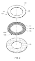
- FIG. 2 is an exploded perspective view of the slip ring of FIG. 1
- FIG. 3 is a cross-sectional view of the slip ring taken along line A-A' of FIG. 1 .
- a slip ring assembly 100 may include a first member 110, a second member 120 facing one surface of the first member 110, rotating relatively with respect to the first member 110, and formed of a conductive material, and a bearing member 130 fixed to the first member 110 so as to be provided between the first and second members 110 and 120, wherein the first and second members 110 and 120 respectively, electrically contact the bearing member 130. That is, the first and second members 110 and 120 and the bearing member 130 may be electrically connected to each other to supply power or transfer a control signal.
- the first and second members 110 and 120 may rotate relatively with respect to each other through the bearing member 130 interposed therebetween. Therefore, in a case in which the first member 110 is a fixed member, the second member 120 may be a rotating member, and in a case in which the first member 110 is a rotating member, the second member 120 may be a fixed member. That is, the first and second members may be appropriately applied depending on a case or a condition.
- the first member 110 is a rotating member, that is, a rotating wheel 110 and the second member 120 is a fixed member, that is, a fixed wheel 120 will be described in detail by way of example.
- the fixed wheel 120 may be a part fixed in utilizing the slip ring assembly 100 and the rotating wheel 110 may be a part rotating in utilizing the slip ring assembly 100.
- the rotating wheel 110 may rotate together with a pedal of a bicycle in a state in which it is fixed to a rotational shaft of the pedal of the bicycle, and the fixed wheel 120 may be fixed to a non-rotating part of the bicycle.
- the slip ring assembly 100 may include the rotating wheel 110 and the fixed wheel 120.
- the rotating wheel 110 may be a member fixed to a rotating member, for example, a rotational shaft, or the like, to rotate together with the rotating member, and the fixed wheel 120 may be a member fixed to a part other than the rotational shaft in a state in which it maintains an electrical contact with the rotating wheel 110.
- one of the rotating wheel 110 and the fixed wheel 120 may be provided with the bearing member 130.
- the bearing member 130 may be fixed to one of the rotating wheel 110 and the fixed wheel 120 so as to smoothly rotate while maintaining a state of contact between the rotating wheel 110 and the fixed wheel 120 performing relative rotation.
- FIGS. 1 through 3 a structure in which the bearing member 130 is fixed to the rotating wheel 110 has been illustrated in FIGS. 1 through 3 , the present disclosure is not limited thereto. That is, the bearing member 130 may also be fixed to the fixed wheel 120.
- the slip ring assembly 100 may be a device allowing an electrical circuit, a power supply, and the like, of the fixed member and an electrical circuit, a power supply, and the like, of the rotating member to be electrically connected to each other without twisting a wiring during rotation of the rotating member.
- the slip ring assembly 100 may be mounted on the rotational shaft (the rotating member) of the pedal of the bicycle to measure a rotational torque of the pedal and be used to transfer the measured rotational torque to a controller provided in another part (the fixed member) of the bicycle.
- the bearing member 130 is fixed to the rotating wheel 110 by way of example.
- the bearing member 130 may also be fixed to the fixed wheel 120 in the same structure.
- the bearing member 130 may be provided on the rotating wheel 110.
- the bearing member 130 may rotate in a state in which it maintains a contact with the fixed wheel 120.
- the slip ring assembly 100 may have a ring shape in which a central part thereof is hollow.
- the rotational shaft may be fitted into the hollow of the slip ring assembly.
- an outer side surface of the slip ring assembly may have various shapes such as a circular shape, or an oval shape, a polygonal shape, and the like, as long as the slip ring assembly has the ring shape in which the central part thereof is hollow.
- the rotating wheel 110 configuring the slip ring assembly 100 may also have a ring shape in which it has a hollow formed therein, and may be fixed in a state in which it is fitted onto the rotational shaft to thereby rotate together with the rotational shaft.
- the rotating wheel 110 may be formed of a printed circuit board (PCB) to be easily utilized.
- the rotating wheel 110 may be provided with the bearing member 130 disposed in a circumferential direction.
- the rotating wheel 110 needs to continuously maintain an electrical connection with the fixed wheel 120 rotating relatively with respect thereto. Therefore, the bearing member 130 interposed between the rotating wheel 110 and the fixed wheel 120 may continuously maintain the electrical connection between the fixed wheel 120 and the rotating wheel 110 while smoothing the rotation.
- the bearing member 130 may have a structure in which a plurality of rotating rollers 131 having rotational axes provided in a radial direction and having a cylindrical shape are disposed to be spaced apart from each other by a predetermined interval in the circumferential direction.
- the rotating rollers 131 are fixed by constraining members 133 rotatably constraining the rotating rollers 131 at both sides of the rotating rollers 131 in the circumferential direction so that the rotational shafts thereof are provided in the radial direction has been illustrated in FIG. 2
- the present disclosure is not limited thereto.
- the rotating rollers 131 may also be provided to be rotatable by the rotational shaft provided in the radial direction along the rotational shafts of the rotating rollers 131.
- the bearing member 130 may include a frame 135 fixed to the rotating member 110.
- the frame 135 may include a rail groove 135a formed in the circumferential direction so that the rotating rollers 131 are mounted therein, wherein the rail groove 135a may have a ' ⁇ ' shaped cross section.
- the bearing member 130 including the frame 135 may also configure the rotating wheel by itself.
- the fixed wheel 120 may be provided in a state in which it maintains a contact with the bearing member 130. That is, the fixed wheel 120 may have a ring shape in which a central part thereof is hollow.
- the rotational shaft may be fitted into the hollow formed in the central part of the fixed wheel 120.
- the fixed wheel 120 is not fixed to the rotational shaft, but is fixed to an external fixing member. That is, the fixed wheel 120 may be maintained in a state in which it is fixed without rotating with the rotational shaft even though the rotational shaft rotates.
- an outer side surface of the fixed wheel may have various shapes such as a circular shape, or an oval shape, a polygonal shape, and the like, as long as the fixed wheel has the ring shape in which the central part thereof is hollow.
- the fixed wheel 120 and the bearing member 130 need to be maintained in a state in which they are electrically connected to each other. Therefore, the fixed wheel 120 and the rotating rollers 131 of the bearing member 130 may be at least partially formed of a conductive material. Only in this case, the fixed wheel 120 and the bearing member 130 may continuously maintain a contact therebetween to prevent the supply of power from being stopped or a transfer of a signal from being stopped.
- the rotating rollers 131 of the bearing member 130 may be formed of a material containing copper that may lower a contact resistance (for example, copper, brass, or the like).
- a contact resistance for example, copper, brass, or the like.
- some of the plurality of rotating rollers 131 provided in the circumferential direction may be formed of the copper, and the others thereof may be formed of a material having good strength in spite of having a comparatively high contact resistance, such as a stainless material, or the like.
- rotating rollers 131 themselves may be electrically connected to each other while frictionally contacting the fixed wheel 120.
- the rotating rollers 131 may be electrically connected to the electrical circuit, the power supply, or the like, of the rotating member.
- a terminal part (not illustrated) of the board and the frame 135 in which the rotating rollers 131 are provided may be electrically connected to each other, and the terminal part of the printed circuit board may be electrically connected to the electrical circuit, the power supply, or the like, of the rotating member.
- the rotating rollers 131 need to frictionally contact the frame 135 to continuously maintain an electrical connection with the frame.
- the rotating rollers 131 may frictionally contact the rotating wheel 110, and the rotating wheel 110 may be electrically connected to an electrical circuit, a power supply, or the like, of an internal component.
- the bearing member 130 including the frame 135 configures the rotating wheel by itself
- the bearing member 130 may frictionally contact the frame 135, and a terminal part 135b of the frame 135 may be electrically connected to the electrical circuit, the power supply, or the like, of the internal component.
- the fixed wheel 120 may include a terminal part 121, which may be connected to a lead wire 125 connected to the outside.
- the lead wire 125 may be connected to an external power supply, a controller, or the like, to supply power or transfer a control signal.
- the power or the control signal may be transferred to the internal component, or the like, through the fixed wheel 120, the bearing member 130, and the rotating wheel 110.
- a signal of the internal component, or the like may be transferred to the controller.
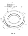
- FIG. 4 is a perspective view illustrating a slip ring according to another exemplary embodiment of the present disclosure
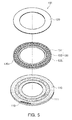
- FIG. 5 is an exploded perspective view of the slip ring of FIG. 4
- FIG. 6 is a cross-sectional view of the slip ring taken along line B-B' of FIG. 4 .
- a slip ring assembly 101 according to another exemplary embodiment of the present disclosure is different from the slip ring assembly 100 according to the exemplary embodiment of the present disclosure illustrated in FIGS. 1 through 3 in that the rotating wheel 110 formed of the printed circuit board is provided with an inner side terminal 111 and outer side terminals 113.
- a difference between the slip ring assembly 101 according to the present exemplary embodiment and the slip ring assembly 100 according to the exemplary embodiment illustrated in FIGS. 1 through 3 will be mainly decreased, and a description for the same components therebetween will be replaced by the above-mentioned description.
- the rotating wheel 110 may include the inner side terminal 111 and the outer side terminals 113.
- the inner side terminal 111 may be provided in a shape corresponding to that of the frame 135 of the bearing member 130 on one surface of the rotating wheel 110. That is, a terminal formed of a conductive material may be provided in the shape corresponding to that of the frame 135 of the bearing member 130 on one surface of the rotating wheel 110, and the frame 135 may be fixed to contact a part in which the inner side terminal 111 is provided.
- the frame 135 is formed of a conductive material, it is connected to the inner side terminal 111, whereby the bearing member 130 and the inner side terminal 111 may be electrically connected to each other.
- the rotating wheel 110 may include the outer side terminals 113 electrically connected to the inner side terminal 111.
- the outer side terminals 113 may be provided at an inner side or an outer side of the frame 135 in the radial direction. Although a case in which the outer side terminals 113 are provided at the outer side of the frame 135 in the radial direction has been illustrated in FIGS. 4 through 6 , the present disclosure is not limited thereto.
- the outer side terminals 113 may be provided at the inner side of the frame 135 in the radial direction.
- the outer side terminals 113 may be electrically connected to the inner side terminal 111 through vias 112 provided in the rotating wheel 110.
- the outer side terminals 113 may be provided in pattern shapes protruding from any one side of the inner side terminal 111 in the radial direction. That is, the outer side terminals 113 may be formed by extending the inner side terminal 111. In this case, the vias need not to be separately formed, and the outer side terminals 113 may be formed while forming the inner side terminal 111, such that it may be very easy to manufacture the slip ring assembly.
- FIGS. 7 and 8 are cross-sectional views illustrating a slip ring according to another exemplary embodiment of the present disclosure.
- a slip ring assembly 103 may have a structure in which a pair of rotating wheels (rotating members) are coupled to one fixed wheel (fixed member) or a pair of fixed wheels (fixed wheels) are coupled to one rotating wheel (rotating member).
- a slip ring assembly 103 in which a pair of fixed members 120a and 120b are coupled to one rotating member 110 may include the rotating member 110, the pair of fixed members 120a and 120b facing both side surfaces of the rotating member 110, respectively, and formed of a conductive material, and a pair of bearing members 130a and 130b fixed to the rotating member 110 or the fixed members 120a and 120b to be provided between the rotating member 110 and the pair of fixed members 120a and 120b, respectively, wherein the rotating member 110 and the fixed members 120a and 120b may electrically contact the bearing members, respectively.
- a slip ring assembly 103 in which a pair of rotating members 110a and 110b are coupled to one fixed member 120 may include the fixed member 120, the pair of rotating members 110a and 110b facing both side surfaces of the fixed member 120, respectively, rotating relatively with respect to the fixed member 120, and formed of a conductive material, and a pair of bearing members 130a and 130b fixed to the fixed member 120 or the rotating members 110a and 110b to be provided between the fixed member 120 and the pair of rotating members 110a and 110b, respectively, wherein the fixed member 120 and the rotating members 110a and 110b may electrically contact the bearing members, respectively.
- the slip ring assembly 103 illustrated in FIGS. 7 and 8 may have a structure in which the pair of rotating wheels (rotating members) are coupled to both surfaces of one fixed wheel (fixed member), respectively, or the pair of fixed wheels (fixed members) are coupled to both surfaces of one rotating wheel (rotating member), respectively, as compared with the slip ring assemblies described above with reference to FIGS. 1 through 6 . Therefore, in the case in which a plurality of connection lines are required to supply the power, transfer the control signal, or the like, a composite coupling structure in which the pair of rotating wheels (or fixed wheels) are coupled to one fixed wheel (or rotating wheel) as shown in FIGS. 7 and 8 may be used to decrease an entire thickness of the slip ring assembly 103.
- slip ring assembly 103 shown in FIGS. 7 and 8 is the same as the slip ring assemblies described above with reference to FIGS. 1 through 6 in that it has a structure in which the fixed wheel and the rotating wheel are coupled to each other through the bearing member except for the composite coupling structure in which the pair of rotating wheels (or fixed wheels) are coupled to one fixed wheel (or rotating wheel), a detail description therefor will be replaced by the description provided with reference to FIGS. 1 through 6 .
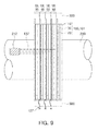
- FIG. 9 is a perspective view illustrating an example in which the slip rings of FIGS. 1 through 6 are mounted on a rotational shaft.
- the slip ring assemblies 100 and 101 may be mounted on a rotational shaft 200 that rotates.
- a sensor, a component, or the like, requiring an external control signal, external power, or the like, such as an electric circuit, a power supply, or the like, may be mounted in a rotating member including the rotational shaft 200. Therefore, the slip ring assemblies 100 and 101 according to the present exemplary embodiment may be mounted in order to receive the external control signal, the external power.
- the rotating wheel 110 including the bearing member 130 among components of the slip ring assembly 100 may be fixed to the rotational shaft 200, and the fixed wheel 120 may rotate relatively with respect to the rotational shaft 200 in a state in which it frictionally contacts the bearing member 130. Therefore, the fixed wheel 120 may be fixed to an entire frame 300 fixed to a member that does not rotate.
- a sensor 210 for measuring a torque applied to a rotating pedal of an electrical bicycle is mounted on a rotational shaft (corresponding to the rotational shaft 200 of FIG. 9 ) of the rotating pedal and power lines, control lines, and signal lines required for an operation of the sensor are connected to a sensor mounted in the rotating member (the rotating wheel 110) and are led to the fixed member (the fixed wheel 120).
- the slip ring assemblies 100 and 101 may be provided to be overlapped with triply or more or be provided to be spaced apart from each other by a predetermined interval (in the slip ring assemblies 100 and 101 according to the present exemplary embodiment, one unit may be in charge of the supply of one power, control signal, or the like), and may be mounted on the rotational shaft 200.
- the power lines, the control lines, and the signal lines may be connected to the slip ring assemblies 100 and 101, respectively.
- the rotating rollers 131 of the respective slip ring assemblies 100 and 101 need to be electrically connected to the sensor 210 through internal lead wires 137 (be electrically connected to the sensor through the rotating wheels 110 or the frames 135 or be electrically connected directly to the sensor), and external lead wires 127 may be connected to the fixed wheels 120 of the slip ring assembles 100 and 101 to allow the power to be supplied from the outside or allow the control signal to be transferred to the inside or the outside.
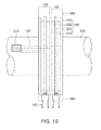
- FIG. 10 is a perspective view illustrating an example in which the slip rings of FIGS. 7 and 8 are mounted on a rotational shaft.
- the slip ring assemblies 103 according to the exemplary embodiment of the present disclosure may be mounted on a rotational shaft 200 that rotates.
- the slip ring assemblies 103 according to the present exemplary embodiment may be to complement a disadvantage that the entire volume may become large in the case in which the numbers of power lines, control signals, and the like, are increased.
- the slip ring assembly 103 described with reference to FIGS. 7 and 8 may have the composite coupling structure in which the pair of rotating wheels (or fixed wheels) are coupled to one fixed wheel (or rotating wheel). That is, the slip ring assembly 103 may have a structure in which one fixed wheel (or rotating wheel) forms a module sharing the pair of rotating wheels (or fixed wheel) with each other, such that one module may include two control signal lines (power signal lines).
- the slip ring able to be resistant to abrasion and ensuring a continuous contact point to prevent a contact defect or generation of noise in transferring a signal may be provided.
- the slip ring able to be cheaply produced and provided due to having a simple configuration may be provided.
Landscapes
- Engineering & Computer Science (AREA)
- General Engineering & Computer Science (AREA)
- Mechanical Engineering (AREA)
- Rolling Contact Bearings (AREA)
- Motor Or Generator Frames (AREA)
Applications Claiming Priority (2)
| Application Number | Priority Date | Filing Date | Title |
|---|---|---|---|
| KR20140040778 | 2014-04-04 | ||
| KR1020140070599A KR20150115592A (ko) | 2014-04-04 | 2014-06-11 | 슬립링 |
Publications (2)
| Publication Number | Publication Date |
|---|---|
| EP2928028A2 true EP2928028A2 (de) | 2015-10-07 |
| EP2928028A3 EP2928028A3 (de) | 2016-01-06 |
Family
ID=52784956
Family Applications (1)
| Application Number | Title | Priority Date | Filing Date |
|---|---|---|---|
| EP15161128.2A Withdrawn EP2928028A3 (de) | 2014-04-04 | 2015-03-26 | Gleitring |
Country Status (1)
| Country | Link |
|---|---|
| EP (1) | EP2928028A3 (de) |
Cited By (3)
| Publication number | Priority date | Publication date | Assignee | Title |
|---|---|---|---|---|
| DE102017215237A1 (de) * | 2017-08-31 | 2019-02-28 | Mahle International Gmbh | Elektromotor |
| US20220239201A1 (en) * | 2019-08-29 | 2022-07-28 | Cr Flight L.L.C. | Counter-rotating differential electric motor assembly slip ring assembly |
| US12564527B2 (en) | 2022-03-07 | 2026-03-03 | Hill-Rom Services, Inc. | Patient support apparatus having motorized wheels |
Family Cites Families (4)
| Publication number | Priority date | Publication date | Assignee | Title |
|---|---|---|---|---|
| DE3150427A1 (de) * | 1981-12-19 | 1983-07-14 | Petri Ag, 8750 Aschaffenburg | Kontakteinrichtung zur stromuebertragung zwischen dem lenkrad und der lenksaeule von kraftfahrzeugen |
| US5575664A (en) * | 1995-05-30 | 1996-11-19 | Hughes Aircraft Company | Ball contact rotary connector |
| US20110182542A1 (en) * | 2010-01-28 | 2011-07-28 | Schaeffler Kg | Thrust needle roller bearing with isolating layer |
| CN102593684B (zh) * | 2012-03-08 | 2014-03-26 | 林龙海 | 一种球刷式电滑环 |
-
2015
- 2015-03-26 EP EP15161128.2A patent/EP2928028A3/de not_active Withdrawn
Non-Patent Citations (1)
| Title |
|---|
| None |
Cited By (4)
| Publication number | Priority date | Publication date | Assignee | Title |
|---|---|---|---|---|
| DE102017215237A1 (de) * | 2017-08-31 | 2019-02-28 | Mahle International Gmbh | Elektromotor |
| US20220239201A1 (en) * | 2019-08-29 | 2022-07-28 | Cr Flight L.L.C. | Counter-rotating differential electric motor assembly slip ring assembly |
| US12027950B2 (en) | 2019-08-29 | 2024-07-02 | Cr Flight L.L.C. | Counter-rotating differential electric motor assembly |
| US12564527B2 (en) | 2022-03-07 | 2026-03-03 | Hill-Rom Services, Inc. | Patient support apparatus having motorized wheels |
Also Published As
| Publication number | Publication date |
|---|---|
| EP2928028A3 (de) | 2016-01-06 |
Similar Documents
| Publication | Publication Date | Title |
|---|---|---|
| US20120115335A1 (en) | Slip ring device | |
| JP2735533B2 (ja) | ボール接触子ロータリーコネクタ | |
| JP2015532173A5 (de) | ||
| CN104218419B (zh) | 接触簧片以及使用该接触簧片的电刷接触件 | |
| CN103944029B (zh) | 一种支撑与信号传递一体化轴系 | |
| JP2019040734A (ja) | スリップリング装置 | |
| JP2018122618A (ja) | チャイルドシート | |
| US10404134B2 (en) | Motor | |
| JP6769761B2 (ja) | スリップリング、及びスリップリングを有するスリップリング装置 | |
| EP3295527B1 (de) | Drehbarer verbinder mit federringen | |
| JP6441720B2 (ja) | 回転機構及び回転式スキャナ | |
| JP2011249870A5 (de) | ||
| KR101136402B1 (ko) | 회전 신호 전달장치 | |
| CN110380303B (zh) | 一种基于滚滑结合的长寿命汇流环 | |
| JP2007141668A (ja) | ロータリコネクタ | |
| EP2636925B1 (de) | Rotationsübertragungsmechanismus und Drehstecker | |
| JP5080604B2 (ja) | 同軸コネクタ用回転機構部品および同軸コネクタ | |
| CN107134700B (zh) | 一种向转动件传递电信号的装置 | |
| KR20150115592A (ko) | 슬립링 | |
| CN204577807U (zh) | 一种旋转滑环式电路连接头 | |
| JP2006164900A (ja) | ロータリーブラシ | |
| KR20110081109A (ko) | 케이블 연결 장치 | |
| JP6887914B2 (ja) | スリップリング装置 | |
| JP2018106857A (ja) | 複合ケーブル | |
| CN207317991U (zh) | 一种非接触式转向扭矩传感器 |
Legal Events
| Date | Code | Title | Description |
|---|---|---|---|
| PUAI | Public reference made under article 153(3) epc to a published international application that has entered the european phase |
Free format text: ORIGINAL CODE: 0009012 |
|
| AK | Designated contracting states |
Kind code of ref document: A2 Designated state(s): AL AT BE BG CH CY CZ DE DK EE ES FI FR GB GR HR HU IE IS IT LI LT LU LV MC MK MT NL NO PL PT RO RS SE SI SK SM TR |
|
| AX | Request for extension of the european patent |
Extension state: BA ME |
|
| PUAL | Search report despatched |
Free format text: ORIGINAL CODE: 0009013 |
|
| AK | Designated contracting states |
Kind code of ref document: A3 Designated state(s): AL AT BE BG CH CY CZ DE DK EE ES FI FR GB GR HR HU IE IS IT LI LT LU LV MC MK MT NL NO PL PT RO RS SE SI SK SM TR |
|
| AX | Request for extension of the european patent |
Extension state: BA ME |
|
| RIC1 | Information provided on ipc code assigned before grant |
Ipc: H01R 39/12 20060101AFI20151127BHEP Ipc: F16C 33/34 20060101ALI20151127BHEP Ipc: F16C 19/30 20060101ALN20151127BHEP Ipc: F16C 33/62 20060101ALI20151127BHEP Ipc: F16C 19/46 20060101ALN20151127BHEP |
|
| STAA | Information on the status of an ep patent application or granted ep patent |
Free format text: STATUS: THE APPLICATION IS DEEMED TO BE WITHDRAWN |
|
| 18D | Application deemed to be withdrawn |
Effective date: 20160707 |