EP2928044A1 - Système de transmission d'énergie sans contact à partir d'une bobine primaire à un véhicule comprenant une bobine secondaire pouvant être couplée de manière inductive à la bobine primaire, procédé de positionnement d'un véhicule, procédé de détermination d'une direction et procédé de commande de positionnement - Google Patents
Système de transmission d'énergie sans contact à partir d'une bobine primaire à un véhicule comprenant une bobine secondaire pouvant être couplée de manière inductive à la bobine primaire, procédé de positionnement d'un véhicule, procédé de détermination d'une direction et procédé de commande de positionnement Download PDFInfo
- Publication number
- EP2928044A1 EP2928044A1 EP15000554.4A EP15000554A EP2928044A1 EP 2928044 A1 EP2928044 A1 EP 2928044A1 EP 15000554 A EP15000554 A EP 15000554A EP 2928044 A1 EP2928044 A1 EP 2928044A1
- Authority
- EP
- European Patent Office
- Prior art keywords
- winding
- vehicle
- primary winding
- windings
- primary
- Prior art date
- Legal status (The legal status is an assumption and is not a legal conclusion. Google has not performed a legal analysis and makes no representation as to the accuracy of the status listed.)
- Granted
Links
Images


Classifications
-
- H—ELECTRICITY
- H01—ELECTRIC ELEMENTS
- H01F—MAGNETS; INDUCTANCES; TRANSFORMERS; SELECTION OF MATERIALS FOR THEIR MAGNETIC PROPERTIES
- H01F38/00—Adaptations of transformers or inductances for specific applications or functions
- H01F38/14—Inductive couplings
-
- B—PERFORMING OPERATIONS; TRANSPORTING
- B60—VEHICLES IN GENERAL
- B60L—PROPULSION OF ELECTRICALLY-PROPELLED VEHICLES; SUPPLYING ELECTRIC POWER FOR AUXILIARY EQUIPMENT OF ELECTRICALLY-PROPELLED VEHICLES; ELECTRODYNAMIC BRAKE SYSTEMS FOR VEHICLES IN GENERAL; MAGNETIC SUSPENSION OR LEVITATION FOR VEHICLES; MONITORING OPERATING VARIABLES OF ELECTRICALLY-PROPELLED VEHICLES; ELECTRIC SAFETY DEVICES FOR ELECTRICALLY-PROPELLED VEHICLES
- B60L53/00—Methods of charging batteries, specially adapted for electric vehicles; Charging stations or on-board charging equipment therefor; Exchange of energy storage elements in electric vehicles
- B60L53/10—Methods of charging batteries, specially adapted for electric vehicles; Charging stations or on-board charging equipment therefor; Exchange of energy storage elements in electric vehicles characterised by the energy transfer between the charging station and the vehicle
- B60L53/12—Inductive energy transfer
- B60L53/126—Methods for pairing a vehicle and a charging station, e.g. establishing a one-to-one relation between a wireless power transmitter and a wireless power receiver
-
- B—PERFORMING OPERATIONS; TRANSPORTING
- B60—VEHICLES IN GENERAL
- B60L—PROPULSION OF ELECTRICALLY-PROPELLED VEHICLES; SUPPLYING ELECTRIC POWER FOR AUXILIARY EQUIPMENT OF ELECTRICALLY-PROPELLED VEHICLES; ELECTRODYNAMIC BRAKE SYSTEMS FOR VEHICLES IN GENERAL; MAGNETIC SUSPENSION OR LEVITATION FOR VEHICLES; MONITORING OPERATING VARIABLES OF ELECTRICALLY-PROPELLED VEHICLES; ELECTRIC SAFETY DEVICES FOR ELECTRICALLY-PROPELLED VEHICLES
- B60L53/00—Methods of charging batteries, specially adapted for electric vehicles; Charging stations or on-board charging equipment therefor; Exchange of energy storage elements in electric vehicles
- B60L53/30—Constructional details of charging stations
- B60L53/35—Means for automatic or assisted adjustment of the relative position of charging devices and vehicles
- B60L53/36—Means for automatic or assisted adjustment of the relative position of charging devices and vehicles by positioning the vehicle
-
- B—PERFORMING OPERATIONS; TRANSPORTING
- B60—VEHICLES IN GENERAL
- B60L—PROPULSION OF ELECTRICALLY-PROPELLED VEHICLES; SUPPLYING ELECTRIC POWER FOR AUXILIARY EQUIPMENT OF ELECTRICALLY-PROPELLED VEHICLES; ELECTRODYNAMIC BRAKE SYSTEMS FOR VEHICLES IN GENERAL; MAGNETIC SUSPENSION OR LEVITATION FOR VEHICLES; MONITORING OPERATING VARIABLES OF ELECTRICALLY-PROPELLED VEHICLES; ELECTRIC SAFETY DEVICES FOR ELECTRICALLY-PROPELLED VEHICLES
- B60L53/00—Methods of charging batteries, specially adapted for electric vehicles; Charging stations or on-board charging equipment therefor; Exchange of energy storage elements in electric vehicles
- B60L53/30—Constructional details of charging stations
- B60L53/35—Means for automatic or assisted adjustment of the relative position of charging devices and vehicles
- B60L53/38—Means for automatic or assisted adjustment of the relative position of charging devices and vehicles specially adapted for charging by inductive energy transfer
-
- B—PERFORMING OPERATIONS; TRANSPORTING
- B60—VEHICLES IN GENERAL
- B60L—PROPULSION OF ELECTRICALLY-PROPELLED VEHICLES; SUPPLYING ELECTRIC POWER FOR AUXILIARY EQUIPMENT OF ELECTRICALLY-PROPELLED VEHICLES; ELECTRODYNAMIC BRAKE SYSTEMS FOR VEHICLES IN GENERAL; MAGNETIC SUSPENSION OR LEVITATION FOR VEHICLES; MONITORING OPERATING VARIABLES OF ELECTRICALLY-PROPELLED VEHICLES; ELECTRIC SAFETY DEVICES FOR ELECTRICALLY-PROPELLED VEHICLES
- B60L53/00—Methods of charging batteries, specially adapted for electric vehicles; Charging stations or on-board charging equipment therefor; Exchange of energy storage elements in electric vehicles
- B60L53/60—Monitoring or controlling charging stations
- B60L53/66—Data transfer between charging stations and vehicles
-
- H—ELECTRICITY
- H02—GENERATION; CONVERSION OR DISTRIBUTION OF ELECTRIC POWER
- H02J—ELECTRIC POWER NETWORKS; CIRCUIT ARRANGEMENTS OR SYSTEMS FOR SUPPLYING OR DISTRIBUTING ELECTRIC POWER; SYSTEMS FOR STORING ELECTRIC ENERGY
- H02J50/00—Circuit arrangements or systems for wireless supply or distribution of electric power
- H02J50/90—Circuit arrangements or systems for wireless supply or distribution of electric power involving detection or optimisation of position, e.g. alignment
-
- Y—GENERAL TAGGING OF NEW TECHNOLOGICAL DEVELOPMENTS; GENERAL TAGGING OF CROSS-SECTIONAL TECHNOLOGIES SPANNING OVER SEVERAL SECTIONS OF THE IPC; TECHNICAL SUBJECTS COVERED BY FORMER USPC CROSS-REFERENCE ART COLLECTIONS [XRACs] AND DIGESTS
- Y02—TECHNOLOGIES OR APPLICATIONS FOR MITIGATION OR ADAPTATION AGAINST CLIMATE CHANGE
- Y02T—CLIMATE CHANGE MITIGATION TECHNOLOGIES RELATED TO TRANSPORTATION
- Y02T10/00—Road transport of goods or passengers
- Y02T10/60—Other road transportation technologies with climate change mitigation effect
- Y02T10/70—Energy storage systems for electromobility, e.g. batteries
-
- Y—GENERAL TAGGING OF NEW TECHNOLOGICAL DEVELOPMENTS; GENERAL TAGGING OF CROSS-SECTIONAL TECHNOLOGIES SPANNING OVER SEVERAL SECTIONS OF THE IPC; TECHNICAL SUBJECTS COVERED BY FORMER USPC CROSS-REFERENCE ART COLLECTIONS [XRACs] AND DIGESTS
- Y02—TECHNOLOGIES OR APPLICATIONS FOR MITIGATION OR ADAPTATION AGAINST CLIMATE CHANGE
- Y02T—CLIMATE CHANGE MITIGATION TECHNOLOGIES RELATED TO TRANSPORTATION
- Y02T10/00—Road transport of goods or passengers
- Y02T10/60—Other road transportation technologies with climate change mitigation effect
- Y02T10/7072—Electromobility specific charging systems or methods for batteries, ultracapacitors, supercapacitors or double-layer capacitors
-
- Y—GENERAL TAGGING OF NEW TECHNOLOGICAL DEVELOPMENTS; GENERAL TAGGING OF CROSS-SECTIONAL TECHNOLOGIES SPANNING OVER SEVERAL SECTIONS OF THE IPC; TECHNICAL SUBJECTS COVERED BY FORMER USPC CROSS-REFERENCE ART COLLECTIONS [XRACs] AND DIGESTS
- Y02—TECHNOLOGIES OR APPLICATIONS FOR MITIGATION OR ADAPTATION AGAINST CLIMATE CHANGE
- Y02T—CLIMATE CHANGE MITIGATION TECHNOLOGIES RELATED TO TRANSPORTATION
- Y02T90/00—Enabling technologies or technologies with a potential or indirect contribution to GHG emissions mitigation
- Y02T90/10—Technologies relating to charging of electric vehicles
- Y02T90/12—Electric charging stations
-
- Y—GENERAL TAGGING OF NEW TECHNOLOGICAL DEVELOPMENTS; GENERAL TAGGING OF CROSS-SECTIONAL TECHNOLOGIES SPANNING OVER SEVERAL SECTIONS OF THE IPC; TECHNICAL SUBJECTS COVERED BY FORMER USPC CROSS-REFERENCE ART COLLECTIONS [XRACs] AND DIGESTS
- Y02—TECHNOLOGIES OR APPLICATIONS FOR MITIGATION OR ADAPTATION AGAINST CLIMATE CHANGE
- Y02T—CLIMATE CHANGE MITIGATION TECHNOLOGIES RELATED TO TRANSPORTATION
- Y02T90/00—Enabling technologies or technologies with a potential or indirect contribution to GHG emissions mitigation
- Y02T90/10—Technologies relating to charging of electric vehicles
- Y02T90/14—Plug-in electric vehicles
-
- Y—GENERAL TAGGING OF NEW TECHNOLOGICAL DEVELOPMENTS; GENERAL TAGGING OF CROSS-SECTIONAL TECHNOLOGIES SPANNING OVER SEVERAL SECTIONS OF THE IPC; TECHNICAL SUBJECTS COVERED BY FORMER USPC CROSS-REFERENCE ART COLLECTIONS [XRACs] AND DIGESTS
- Y02—TECHNOLOGIES OR APPLICATIONS FOR MITIGATION OR ADAPTATION AGAINST CLIMATE CHANGE
- Y02T—CLIMATE CHANGE MITIGATION TECHNOLOGIES RELATED TO TRANSPORTATION
- Y02T90/00—Enabling technologies or technologies with a potential or indirect contribution to GHG emissions mitigation
- Y02T90/10—Technologies relating to charging of electric vehicles
- Y02T90/16—Information or communication technologies improving the operation of electric vehicles
Definitions
- the invention relates to a system for contactless transmission of energy from a primary winding to a vehicle comprising a secondary winding inductively coupled to the primary winding, a method for detecting metal pieces in the system, a method for positioning a vehicle, a method for determining a direction and a positioning control method ,
- the invention is therefore the object of developing a positioning of a vehicle in a position of optimal coupling in the non-contact power supply to the vehicle.
- Important features of the invention in the system for non-contact transmission of energy from a primary winding to a one to the primary winding inductively coupled secondary winding comprehensive vehicle are that the primary winding is arranged stationary and can be acted upon by an alternating current, wherein a winding arrangement is arranged stationary, which has a first and a second winding, in particular, wherein the winding arrangement is arranged centrally to the primary winding, wherein each of the first and second windings is composed of at least two sub-windings, the windings wrapped by the sub-windings of each winding being exposed to and spaced from each other by a magnetic flux generated by the primary winding, in particular such that they are devoid of any flux line from that of the primary winding generated river are interspersed together, wherein the partial windings each have such a winding number and a wound surface such that the, in particular changing, magnetic flux of the primary winding induced voltages of the partial windings are equal in amount, in particular, wherein the first winding is arranged
- the advantage here is that a detection of metals is possible, although a strong field is generated by the primary winding. Because the partial windings are arranged in the field or the field is so homogeneous that the voltages induced by the field are equal in amount and are preferably effected with different signs. Therefore, the effect of the variable field of the primary winding is canceled and it can be completely independent of the field of the primary coil, the space area of the contactless energy transfer monitored for the presence of a piece of metal.
- the windings are made the same, including the partial windings of the windings, and the windings are arranged rotated 90 °, with a small spacing of the windings from each other, in particular less than one-tenth of the largest winding diameter is allowed.
- a small spacing of the windings from each other in particular less than one-tenth of the largest winding diameter is allowed.
- the partial windings each have the same winding number and wound surface and the wrapped surfaces are aligned in parallel.
- a further winding arrangement is arranged on the vehicle and likewise has a first and a second winding, which in turn have partial windings.
- the advantage here is that the winding assembly is easy to produce as a printed circuit board winding and thus can be installed in the same way on vehicles and on the stationary part.
- the windings each have a center tap.
- the advantage here is that a particularly simple and cost-effective production of the winding arrangement and with windings and part windings can be produced.
- the windings are made flat, in particular aligned parallel to each other and / or have mutually parallel wound surfaces.
- the advantage here is that a simple production is achievable.
- Important features in the method for detecting metal pieces in a system for the contactless transmission of energy from a primary winding to a secondary winding inductively coupled to the primary winding secondary vehicle are that in the primary winding, an alternating current is impressed, wherein in the region of the primary winding a winding arrangement is arranged, which has a first and a second winding, in particular, wherein the winding arrangement is arranged centrally to the primary winding, wherein the first and second windings are each composed of at least two sub-windings, the windings wound by the sub windings of a respective winding being exposed to and spaced from each other by a magnetic flux generated by the primary winding, in particular such that they are devoid of any flux line from that of the primary winding generated river are interspersed together, wherein the partial windings each have such a winding number and a wound surface such that the, in particular changing, magnetic flux of the primary winding induced voltages of the partial windings are equal in amount, wherein the first winding is
- the advantage here is that metal is detectable and thus the exceeding of a critical temperature can be monitored. In this way, the risk of fire is reduced.
- the partial windings are designed as flat windings, in particular are aligned parallel to each other.
- the advantage here is that the partial windings are aligned on a circuit board.
- the induced voltages of the two partial windings are fed to a Wheatstone bridge circuit.
- the advantage here is that the difference of the induced voltages with a very good signal-to-noise ratio, ie with high sensitivity interference-proof, can be determined.
- Important features in the method of positioning a vehicle in a position of optimum coupling between a primary winding and a secondary winding in a system for non-contact transmission of energy from the primary winding to a vehicle inductively coupled to the primary winding secondary winding vehicle are that in the primary winding an alternating current is imprinted, wherein in each case a winding arrangement is arranged in the region of the primary winding and on the vehicle, which has in each case a first and a second winding, in particular, wherein the winding arrangement arranged in the region of the primary winding is arranged centrally to the primary winding, wherein, in particular after reaching the optimum position, is that the first and second windings are each composed of at least two sub-windings, the windings wound by the sub-windings of a respective winding being exposed to a magnetic flux generated by the primary winding and spaced from each other, in particular such that they are not of any flux line of that generated by the primary winding River are interspersed together, wherein the partial winding
- the advantage here is that a fast and targeted positioning of the vehicle is possible and even during the positioning of the primary winding can be energized with high current, so that the vehicle is already loaded during positioning with energy. Because despite the high fields, the determination of the incorrect positioning with the help of the windings is possible, the windings also serve for data transmission.
- the amounts of the induced voltages are considered in the direction determination, in particular so that overall an improved direction is determined, in which the transmitter is seen from the receiver.
- a display means in particular an optical and / or acoustic display means as parking aid in the vehicle is providable or alternatively an automatic parking of the vehicle is made possible by the specific direction of affypositionier horrung is supplied and this the vehicle in the specific direction at least in sections moved.
- a respective direction is determined in which the vehicle is controlled at least until an updated direction is determined again.
- the advantage here is that a quick achievement of the optimum position is made possible by the vehicle.
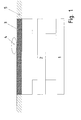
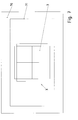
- FIG. 1 is a stationary part of a charging station for an inductively rechargeable electric vehicle schematically outlined.
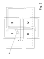
- this winding arrangement belongs to the stationary part and consists of two vertically superimposed windings. However, a similar winding arrangement is also arranged on the vehicle.
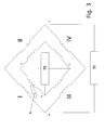
- FIG. 3 are the inductive couplings of the winding arrangement FIG. 2 shown and connected to a transmitter 31 and receiver 30.
- the arrangement after FIG. 3 is therefore provided on the one hand on the stationary part and on the other hand on the vehicle.
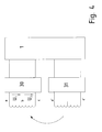
- FIG. 5 different forms of one of the connected to the receiver 30 and transmitter 31 windings are shown.
- FIG. 6 the winding arrangement of the stationary equipment part for data transmission and the corresponding, attached to the electric vehicle winding arrangement for data transmission is shown.
- FIG. 7 the stationary part of the system is shown in plan view.
- the stationary part of the system to a modem 1, which is connected to a transmitter 31 and receiver 30.
- a similar arrangement is arranged, so that with inductive coupling of the with the respective transmitters (31, 631) and receivers (30, 630) connected windings data transmission is possible.
- the modem is turned on at the beginning, then determines the position of the vehicle or at least the direction and / or distance in which the vehicle for optimal position to move.
- the optimum position is understood to be that position which has the maximum coupling between the primary winding and the secondary winding.
- the direction or deviation can be displayed with a display means and / or fed to a positioning control means.
- an identification information can be transmitted and then the energy transfer can be started, so that then the energy storage is rechargeable.
- a charge control is possible, in particular a setting of the power flow on the stationary side, ie to the primary winding out.
- the winding region 3 has a first winding with center tap, that is to say the connections a, b and c.
- a structurally identical winding with the terminals a ', b' and c ' is rotated by 90 ° placed over it.
- Each of the windings has a first and a second partial winding, wherein the two partial windings have spaced-apart wound surfaces.
- the two wrapped surfaces are displaced parallel to a plane receiving one of the wrapped surfaces so that the perpendicular projection of the other wrapped surface into the plane has no intersection with the former wrapped surface.
- both partial windings are designed with such a winding number, wound area size and winding sense that the voltages induced in the two partial windings of a homogeneous field are equal in magnitude, but in particular have opposite sign.
- the homogeneous field is generated by a primary winding 71, the field of which is essentially homogeneous in terms of the winding arrangement. In this way, one of the field of the primary winding 71 completely independent and undisturbed operation in metal detection, vehicle positioning and / or data transmission is possible.
- the wrapped surfaces are equal in amount, the sense of winding different and the number of turns in each case the same.
- the second winding is arranged rotated by 90 °.
- the two partial windings of the second winding are arranged correspondingly rotated over the first winding and there are four coupling regions I, II, III, IV.
- the first winding is used as a transmitter.
- a preferably high-frequency AC voltage for example, with a frequency between 0.5 and 15 MHz, applied to the terminals a and c.
- the alternating voltage is generated by the transmitter 31.
- the voltages induced at the second winding are detected by the receiver 30 and processed.
- the voltage U1 between the terminals a and b occurs and the voltage U2 between the terminals b and c.
- U1 In the presence of a piece of metal 4 in one of the four coupling regions (I, II, III, IV) U1 will thus deviate from U2, in particular exceed a critical deviation amount that is thus recognizable to the receiver 30 that the couplings have different strengths, ie a metal piece 4 is present in the transfer area.
- a warning is triggered and the transmission of power, in particular the impressing of high current into the primary winding 71, is prevented.
- the partial windings each have a rectangular shape.
- a holding part 70 in particular foundation plate, which carries the primary winding 71, in which the winding arrangement, consisting of the two windings, is arranged centrally.
- the partial windings of the windings are arranged symmetrically to the center of symmetry, so that the voltages induced by the primary winding 71 in the partial windings, which are assigned to a respective same winding, are equal in magnitude.
- the transmitter 31 is informed after determining the different coupling strengths, so for example caused by a piece of metal 4, that he should change the frequency.
- the winding assembly of windings each composed of two partial windings, arranged both on the stationary part of the plant, in particular on the ground, as well as on the vehicle.
- a modem 601 is also arranged on the vehicle, which is connected to a transmitter 631 and to a receiver 630.
- the detection of the distance of the vehicle can be determined from an optimal position.
- the optimum position is where the smallest possible distance between the vehicle and the primary winding is reached, in particular where the smallest possible distance between the winding of the vehicle and the winding of the stationary part of the plant and the two windings are aligned in parallel, so the vertical projections of the two windings in the ground containing plane are substantially congruent.
- the primary winding 71 is arranged such that the maximum power can be transmitted at this position.
- the voltages induced at the sub-windings have the maximum amount, depending on the variation of the induced voltage amount, whether the vehicle has approached the optimum position or not. Since two mutually perpendicular windings are arranged on the vehicle side, this determination of the voltage change in two mutually perpendicular directions is made possible. Thus, even the direction to the optimal position can be determined and can be displayed with display means and / or taken into account in an automatic positioning of the vehicle. In such automatic positioning, a control unit controls the vehicle toward the optimum position by supplying the control unit with the specific direction on the input side.
- the phase angle of the voltage induced in a partial winding of the winding of the receiver 630 to the voltage in the winding of the transmitter 31 is also taken into account.
- a synchronization time is communicated in the data transmission, for example by a digital word information. The phase position is then determined relative to this time.
- the phasing is important because the induced voltage is substantially phase-shifted by an angle ⁇ to the transmitter voltage as long as the receiver winding is outside the transmitter winding, that is, the vehicle is at a great distance from the optimum position.
- the transmission time of the electromagnetic waves is neglected because a correspondingly low transmission frequency of less than 15 MHz is used and the distances between the transmitter winding and the receiver winding are less than 3 meters. If the receiver winding overlaps with the transmitter winding, for example, the vertical projections of the two windings each have the same or almost the same wrapped surface, the induced voltage is phase-shifted by an angle ( ⁇ + 180 °).
- the distance range can be determined.
- the partial windings of the winding of the receiver 630 on the vehicle have substantially the same phase position.
- the voltage induced at the first partial winding of the winding then has an opposite sign to one another for the voltage induced at the other partial winding of the winding.
- the phase shift is 180 ° between the two induced voltages.
- the removal of the vehicle from the optimal position can also be determined from the stationary installation, in that instead of the transmitter 31, the transmitter 631 transmits an alternating field at the stationary installation part which the receiver 30 detects and induces from the corresponding part windings Tension determines the distance and / or the direction to the optimal position.
- the distance and / or the direction to the optimal position can also be determined.
- An offset of the vehicle parallel to a lying between the partial windings of a winding center plane, ie a lateral offset to the winding, has no significant impact on the data transmission between the stationary part and the vehicle.
- An offset in the vertical direction for this deteriorates the data transmission strongly - even if there are only small shifts.
- each winding is associated with a further, vertically twisted winding, data transmission is excellently executable via one of the windings, as long as the spacing between the vehicle and the winding region 3 is not greater than the range. Therefore, in further embodiments of the invention, if necessary, the winding with the terminals (a, b, c) is exchanged with the terminals (a ', b', c ') of the other winding.
- information is transmitted by the transmitter 31 and received by a partial winding of the winding of the receiver 630 in a first time segment. Subsequently, in another period, information is received from the other partial winding of the winding. By comparing the amounts of each induced voltages is determined whether it is the first or the other part winding of the winding closer to the receiver.
- a direction is determined along which the vehicle must move as short a distance as possible in order to reach the optimal position after repeated execution of the aforementioned steps.
- the respective amounts of the induced voltages can be taken into account, so that overall an improved direction can be determined, in which the transmitter 31 is viewed from the receiver 630.
- the vehicle gets to the optimum position even in very few repetitions and at larger distances covered.
Landscapes
- Engineering & Computer Science (AREA)
- Power Engineering (AREA)
- Transportation (AREA)
- Mechanical Engineering (AREA)
- Computer Networks & Wireless Communication (AREA)
- Electric Propulsion And Braking For Vehicles (AREA)
- Measurement Of Length, Angles, Or The Like Using Electric Or Magnetic Means (AREA)
- Near-Field Transmission Systems (AREA)
Applications Claiming Priority (3)
| Application Number | Priority Date | Filing Date | Title |
|---|---|---|---|
| DE102011015980.0A DE102011015980B4 (de) | 2011-04-04 | 2011-04-04 | System zur berührungslosen Übertragung von Energie von einer Primärwicklung an ein eine an die Primärwicklung induktiv koppelbare Sekundärwicklung umfassendes Fahrzeug, Verfahren zum Detektieren von Metallstücken bei dem System, Verfahren zum Positionieren eines Fahrzeuges, Verfahren zur Bestimmung einer Richtung und Positioniersteuerverfahren |
| PCT/EP2012/001089 WO2012136303A2 (fr) | 2011-04-04 | 2012-03-12 | Système de transmission d'énergie sans contact entre un bobinage primaire et un véhicule comprenant un bobinage secondaire qui peut être couplé inductivement avec le bobinage primaire, procédé de détection de pièces métalliques dans le système, procédé de positionnement d'un véhicule, procédé de détermination d'une direction et procédé de commande du positionnement |
| EP12712220.8A EP2695280B1 (fr) | 2011-04-04 | 2012-03-12 | Système de transmission d'énergie sans contact à un véhicule, procédé de détection de pièces métalliques dans le système, procédé de positionnement d'un véhicule, procédé de détermination de direction du véhicule pour placement optimal |
Related Parent Applications (2)
| Application Number | Title | Priority Date | Filing Date |
|---|---|---|---|
| EP12712220.8A Division EP2695280B1 (fr) | 2011-04-04 | 2012-03-12 | Système de transmission d'énergie sans contact à un véhicule, procédé de détection de pièces métalliques dans le système, procédé de positionnement d'un véhicule, procédé de détermination de direction du véhicule pour placement optimal |
| EP12712220.8A Division-Into EP2695280B1 (fr) | 2011-04-04 | 2012-03-12 | Système de transmission d'énergie sans contact à un véhicule, procédé de détection de pièces métalliques dans le système, procédé de positionnement d'un véhicule, procédé de détermination de direction du véhicule pour placement optimal |
Publications (2)
| Publication Number | Publication Date |
|---|---|
| EP2928044A1 true EP2928044A1 (fr) | 2015-10-07 |
| EP2928044B1 EP2928044B1 (fr) | 2020-10-21 |
Family
ID=45930642
Family Applications (2)
| Application Number | Title | Priority Date | Filing Date |
|---|---|---|---|
| EP12712220.8A Active EP2695280B1 (fr) | 2011-04-04 | 2012-03-12 | Système de transmission d'énergie sans contact à un véhicule, procédé de détection de pièces métalliques dans le système, procédé de positionnement d'un véhicule, procédé de détermination de direction du véhicule pour placement optimal |
| EP15000554.4A Active EP2928044B1 (fr) | 2011-04-04 | 2012-03-12 | Système de transmission d'énergie sans contact à partir d'une bobine primaire à un véhicule comprenant une bobine secondaire pouvant être couplée de manière inductive à la bobine primaire, procédé de positionnement d'un véhicule, procédé de détermination d'une direction et procédé de commande de positionnement |
Family Applications Before (1)
| Application Number | Title | Priority Date | Filing Date |
|---|---|---|---|
| EP12712220.8A Active EP2695280B1 (fr) | 2011-04-04 | 2012-03-12 | Système de transmission d'énergie sans contact à un véhicule, procédé de détection de pièces métalliques dans le système, procédé de positionnement d'un véhicule, procédé de détermination de direction du véhicule pour placement optimal |
Country Status (3)
| Country | Link |
|---|---|
| EP (2) | EP2695280B1 (fr) |
| DE (1) | DE102011015980B4 (fr) |
| WO (1) | WO2012136303A2 (fr) |
Cited By (2)
| Publication number | Priority date | Publication date | Assignee | Title |
|---|---|---|---|---|
| CN104682488A (zh) * | 2014-12-26 | 2015-06-03 | 中兴新能源汽车有限责任公司 | 异物检测装置、方法及无线充电系统 |
| WO2017218831A1 (fr) * | 2016-06-16 | 2017-12-21 | Evatran Group, Inc. | Système et procédé d'alignement passif |
Families Citing this family (25)
| Publication number | Priority date | Publication date | Assignee | Title |
|---|---|---|---|---|
| US9260026B2 (en) | 2011-07-21 | 2016-02-16 | Ut-Battelle, Llc | Vehicle to wireless power transfer coupling coil alignment sensor |
| JP6185472B2 (ja) | 2011-09-09 | 2017-08-23 | ワイトリシティ コーポレーションWitricity Corporation | ワイヤレスエネルギー伝送システムにおける異物検出 |
| DE112012005961A5 (de) * | 2012-02-29 | 2014-12-11 | Siemens Aktiengesellschaft | Ladesystem zum galvanisch getrennten Aufladen eines elektrischen Energiespeichers eines Fahrzeigs, elektrisch angetriebenes Fahrzeug, Ladestation für ein Fahrzeug und entsprechendes Verfahren |
| WO2013189530A1 (fr) * | 2012-06-20 | 2013-12-27 | Siemens Aktiengesellschaft | Module à bobines de détection, module à bobines de transfert d'énergie et système de détection pour la reconnaissance de corps étrangers électriquement conducteurs |
| DE102012019751B4 (de) * | 2012-10-09 | 2020-03-12 | Sew-Eurodrive Gmbh & Co Kg | Verfahren zum Bestimmen der Richtung einer relativen Geschwindigkeit zwischen einer Sendeinduktivität und einer Empfangsinduktivität, Verfahren zum Einparken eines Fahrzeugs und System zur Durchführung eines Verfahrens |
| WO2014063159A2 (fr) * | 2012-10-19 | 2014-04-24 | Witricity Corporation | Détection de corps étranger dans des systèmes de transfert d'énergie sans fil |
| EP2727759B1 (fr) * | 2012-11-05 | 2015-01-14 | Alcatel Lucent | Procédé et dispositif pour un système d'assistance de véhicule |
| GB2508923A (en) * | 2012-12-17 | 2014-06-18 | Bombardier Transp Gmbh | Inductive power transfer system having inductive sensing array |
| GB2508924A (en) * | 2012-12-17 | 2014-06-18 | Bombardier Transp Gmbh | Inductive power transfer system having array of sensing capacitors |
| GB2520990A (en) | 2013-12-06 | 2015-06-10 | Bombardier Transp Gmbh | Inductive power transfer for transferring electric energy to a vehicle |
| DE102014003028B3 (de) * | 2014-03-07 | 2015-05-07 | Sew-Eurodrive Gmbh & Co Kg | Verfahren und System zur Durchführung eines Verfahrens zur Bestimmung eines Wertes für den Versatz der senkrechten Projektionen zweier Wicklungen |
| DE102014005531B4 (de) * | 2014-04-16 | 2023-09-07 | Sew-Eurodrive Gmbh & Co Kg | Ladeanordnung zur induktiven Beladung des Energiespeichers eines Fahrzeugs und Verfahren zum Betreiben einer Ladeanordnung |
| DE102014207427A1 (de) | 2014-04-17 | 2015-10-22 | Bombardier Transportation Gmbh | Vorrichtung und Verfahren zur Detektion eines Störkörpers in einem System zur induktiven Energieübertragung sowie System zur induktiven Energieübertragung |
| US10270293B2 (en) | 2014-07-29 | 2019-04-23 | Qualcomm Technologies International, Ltd. | Wireless charger with resonator |
| DE102014017544A1 (de) * | 2014-11-28 | 2016-06-02 | Sew-Eurodrive Gmbh & Co Kg | Verfahren und System zum induktiven Übertragen von elektrischer Energie an ein Fahrzeug |
| DE102015006298B4 (de) | 2015-05-16 | 2022-01-27 | Audi Ag | Ladestation für Kraftfahrzeuge und Verfahren zum Betreiben einer Ladestation |
| EP3103674B1 (fr) | 2015-06-12 | 2021-08-18 | Brusa Elektronik AG | Systeme de determination de position, procede de determination de position et systeme inductif de transfert d'energie a l'aide d'un systeme de determination de position |
| US10461587B2 (en) * | 2016-09-19 | 2019-10-29 | Witricity Corporation | Methods and apparatus for positioning a vehicle using foreign object detection |
| US10892632B2 (en) | 2017-08-15 | 2021-01-12 | Toyota Motor Engineering & Manufacturing North America, Inc. | Configurable grid charging coil with active switch and sensing system |
| US10668828B2 (en) | 2017-09-13 | 2020-06-02 | Toyota Motor Engineering & Manufacturing North America, Inc. | Multi-coil charging system for distributed in-wheel motors |
| US10850634B2 (en) | 2017-10-20 | 2020-12-01 | Toyota Motor Engineering & Manufacturing North America, Inc. | Multi-turn configurable grid charging coil |
| CN110370958B (zh) * | 2019-08-23 | 2024-06-04 | 天津工业大学 | 一种无线充电的定位辅助检测系统 |
| DE102020200199A1 (de) | 2020-01-09 | 2021-07-15 | Vitesco Technologies GmbH | Detektion von leitfähigen Gegenständen an oder über einer Oberfläche |
| CN116262445B (zh) * | 2021-12-15 | 2025-08-01 | 宇通客车股份有限公司 | 一种无线充电系统引导与对位方法及车辆 |
| DE112023003465A5 (de) * | 2022-08-16 | 2025-06-05 | Mahle International Gmbh | Verfahren zum Positionieren eines Fahrzeugs |
Citations (5)
| Publication number | Priority date | Publication date | Assignee | Title |
|---|---|---|---|---|
| WO2008051611A2 (fr) | 2006-10-25 | 2008-05-02 | Farkas Laszio | Systeme de transfert d'energie resonant sans fil a haute puissance |
| JP2008288889A (ja) * | 2007-05-17 | 2008-11-27 | Showa Aircraft Ind Co Ltd | 信号伝送コイル通信装置 |
| DE102009013694A1 (de) | 2009-03-20 | 2010-09-23 | Paul Vahle Gmbh & Co. Kg | Energieübertragungssystem mit mehreren Primärspulen |
| DE102009033239A1 (de) | 2009-07-14 | 2011-01-20 | Conductix-Wampfler Ag | Vorrichtung zur induktiven Übertragung elektrischer Energie |
| DE102009033237A1 (de) | 2009-07-14 | 2011-01-20 | Conductix-Wampfler Ag | Vorrichtung zur induktiven Übertragung elektrischer Energie |
Family Cites Families (2)
| Publication number | Priority date | Publication date | Assignee | Title |
|---|---|---|---|---|
| WO2010133501A1 (fr) * | 2009-05-18 | 2010-11-25 | Sick Ag | Capteur destiné à détecter des objets métalliques |
| DE202009009693U1 (de) * | 2009-07-14 | 2010-11-25 | Conductix-Wampfler Ag | Vorrichtung zur induktiven Übertragung elektrischer Energie |
-
2011
- 2011-04-04 DE DE102011015980.0A patent/DE102011015980B4/de active Active
-
2012
- 2012-03-12 WO PCT/EP2012/001089 patent/WO2012136303A2/fr not_active Ceased
- 2012-03-12 EP EP12712220.8A patent/EP2695280B1/fr active Active
- 2012-03-12 EP EP15000554.4A patent/EP2928044B1/fr active Active
Patent Citations (5)
| Publication number | Priority date | Publication date | Assignee | Title |
|---|---|---|---|---|
| WO2008051611A2 (fr) | 2006-10-25 | 2008-05-02 | Farkas Laszio | Systeme de transfert d'energie resonant sans fil a haute puissance |
| JP2008288889A (ja) * | 2007-05-17 | 2008-11-27 | Showa Aircraft Ind Co Ltd | 信号伝送コイル通信装置 |
| DE102009013694A1 (de) | 2009-03-20 | 2010-09-23 | Paul Vahle Gmbh & Co. Kg | Energieübertragungssystem mit mehreren Primärspulen |
| DE102009033239A1 (de) | 2009-07-14 | 2011-01-20 | Conductix-Wampfler Ag | Vorrichtung zur induktiven Übertragung elektrischer Energie |
| DE102009033237A1 (de) | 2009-07-14 | 2011-01-20 | Conductix-Wampfler Ag | Vorrichtung zur induktiven Übertragung elektrischer Energie |
Cited By (2)
| Publication number | Priority date | Publication date | Assignee | Title |
|---|---|---|---|---|
| CN104682488A (zh) * | 2014-12-26 | 2015-06-03 | 中兴新能源汽车有限责任公司 | 异物检测装置、方法及无线充电系统 |
| WO2017218831A1 (fr) * | 2016-06-16 | 2017-12-21 | Evatran Group, Inc. | Système et procédé d'alignement passif |
Also Published As
| Publication number | Publication date |
|---|---|
| EP2695280A2 (fr) | 2014-02-12 |
| WO2012136303A3 (fr) | 2012-12-06 |
| EP2928044B1 (fr) | 2020-10-21 |
| DE102011015980B4 (de) | 2021-05-06 |
| DE102011015980A1 (de) | 2012-10-04 |
| WO2012136303A2 (fr) | 2012-10-11 |
| EP2695280B1 (fr) | 2015-08-19 |
Similar Documents
| Publication | Publication Date | Title |
|---|---|---|
| EP2695280B1 (fr) | Système de transmission d'énergie sans contact à un véhicule, procédé de détection de pièces métalliques dans le système, procédé de positionnement d'un véhicule, procédé de détermination de direction du véhicule pour placement optimal | |
| EP2550174B1 (fr) | Système de transfert d'énergie sans contact sur un véhicule | |
| DE102011083427A1 (de) | System zur Positionsbestimmung von zueinander beweglichen Objekten | |
| EP2683572B1 (fr) | Système de transfert d'énergie et des données sans contact à un véhicule | |
| DE102011115092B4 (de) | System zur kontaktlosen Übertragung von Energie und Daten | |
| EP3350015B1 (fr) | Procédé de détermination d'une information de position décrivant une position relative d'un véhicule automobile par rapport à un dispositif de charge immobile à approcher et ensemble constitué d'un véhicule automobile et d'un dispositif de charge fixe à approcher | |
| DE102011014521A1 (de) | Einrichtung zur induktiven Übertragung elektrischer Energie | |
| DE102014202747A1 (de) | Vorrichtung zum Erfassung einer Lageabweichung der passiven Spule gegenüber der Primärspule eines induktiven Ladesystems für ein Fahrzeug sowie zugehöriges Verfahren | |
| EP3178148A1 (fr) | Recouvrement de bobine | |
| WO2013189530A1 (fr) | Module à bobines de détection, module à bobines de transfert d'énergie et système de détection pour la reconnaissance de corps étrangers électriquement conducteurs | |
| DE102009049432A1 (de) | Ladestation | |
| DE102020120990A1 (de) | Vorrichtung zur erkennung von fremdstoffen | |
| DE102012010014B3 (de) | Verfahren zur Bestimmung der Position einer mobilen Einheit und Anlage zur Durchführung eines Verfahrens | |
| DE102012019751B4 (de) | Verfahren zum Bestimmen der Richtung einer relativen Geschwindigkeit zwischen einer Sendeinduktivität und einer Empfangsinduktivität, Verfahren zum Einparken eines Fahrzeugs und System zur Durchführung eines Verfahrens | |
| EP3046799A2 (fr) | Procédé et système pour faire fonctionner un véhicule, en particulier un véhicule déplaçable le long d'un sol | |
| EP2689537B1 (fr) | Dispositif comportant une partie stationnaire et une partie mobile disposée mobile par rapport à la partie stationnaire | |
| DE102012023708A1 (de) | Verfahren und System zur Bestimmung der relativen Position zwischen einer mobilen Einheit und einem Sender | |
| EP2421722B1 (fr) | Installation comprenant un système de conducteur primaire et un véhicule | |
| DE102010027639A1 (de) | Spuleneinrichtung und Spulenanordnung | |
| DE102011104848A1 (de) | Vorrichtung zur zerstörungsfreien Prüfung von metallischem Langgut sowie Verwendung der Vorrichtung | |
| EP3224926B1 (fr) | Procédé et système d'exploitation d'une station de charge pour la transmission inductive d'énergie électrique à un véhicule avec accumulateur d'énergie | |
| DE102014002883A1 (de) | System zur Detektion eines Metallteils, insbesondere in einem Raumbereich | |
| DE102014003028B3 (de) | Verfahren und System zur Durchführung eines Verfahrens zur Bestimmung eines Wertes für den Versatz der senkrechten Projektionen zweier Wicklungen | |
| DE102012019416A1 (de) | Verfahren zur Bestimmung eines Abstandes zwischen einer Sendeinduktivität und einer Empfangsinduktivität und Vorrichtung zur Durchführung des Verfahrens | |
| DE102015011950A1 (de) | Ladesystem, umfassend ein auf einem Boden verfahrbares Fahrzeug und ein auf dem Boden angeordnetes Aufnahmeteil, und Verfahren zum Betreiben eines Systems zur induktiven Übertragung elektrischer Energie von einer Primärspule an eine Sekundärspule |
Legal Events
| Date | Code | Title | Description |
|---|---|---|---|
| PUAI | Public reference made under article 153(3) epc to a published international application that has entered the european phase |
Free format text: ORIGINAL CODE: 0009012 |
|
| 17P | Request for examination filed |
Effective date: 20150226 |
|
| AC | Divisional application: reference to earlier application |
Ref document number: 2695280 Country of ref document: EP Kind code of ref document: P |
|
| AK | Designated contracting states |
Kind code of ref document: A1 Designated state(s): AL AT BE BG CH CY CZ DE DK EE ES FI FR GB GR HR HU IE IS IT LI LT LU LV MC MK MT NL NO PL PT RO RS SE SI SK SM TR |
|
| 17Q | First examination report despatched |
Effective date: 20151023 |
|
| RBV | Designated contracting states (corrected) |
Designated state(s): AL AT BE BG CH CY CZ DE DK EE ES FI FR GB GR HR HU IE IS IT LI LT LU LV MC MK MT NL NO PL PT RO RS SE SI SK SM TR |
|
| STAA | Information on the status of an ep patent application or granted ep patent |
Free format text: STATUS: EXAMINATION IS IN PROGRESS |
|
| RIC1 | Information provided on ipc code assigned before grant |
Ipc: B60L 53/66 20190101ALI20200324BHEP Ipc: B60L 53/36 20190101ALI20200324BHEP Ipc: H02J 7/02 20160101AFI20200324BHEP Ipc: B60L 53/126 20190101ALI20200324BHEP Ipc: B60L 53/38 20190101ALI20200324BHEP Ipc: H01F 38/14 20060101ALI20200324BHEP |
|
| GRAP | Despatch of communication of intention to grant a patent |
Free format text: ORIGINAL CODE: EPIDOSNIGR1 |
|
| STAA | Information on the status of an ep patent application or granted ep patent |
Free format text: STATUS: GRANT OF PATENT IS INTENDED |
|
| INTG | Intention to grant announced |
Effective date: 20200526 |
|
| GRAS | Grant fee paid |
Free format text: ORIGINAL CODE: EPIDOSNIGR3 |
|
| GRAA | (expected) grant |
Free format text: ORIGINAL CODE: 0009210 |
|
| STAA | Information on the status of an ep patent application or granted ep patent |
Free format text: STATUS: THE PATENT HAS BEEN GRANTED |
|
| AC | Divisional application: reference to earlier application |
Ref document number: 2695280 Country of ref document: EP Kind code of ref document: P |
|
| AK | Designated contracting states |
Kind code of ref document: B1 Designated state(s): AL AT BE BG CH CY CZ DE DK EE ES FI FR GB GR HR HU IE IS IT LI LT LU LV MC MK MT NL NO PL PT RO RS SE SI SK SM TR |
|
| REG | Reference to a national code |
Ref country code: GB Ref legal event code: FG4D Free format text: NOT ENGLISH |
|
| REG | Reference to a national code |
Ref country code: CH Ref legal event code: EP |
|
| REG | Reference to a national code |
Ref country code: DE Ref legal event code: R096 Ref document number: 502012016435 Country of ref document: DE |
|
| REG | Reference to a national code |
Ref country code: IE Ref legal event code: FG4D Free format text: LANGUAGE OF EP DOCUMENT: GERMAN |
|
| REG | Reference to a national code |
Ref country code: AT Ref legal event code: REF Ref document number: 1326831 Country of ref document: AT Kind code of ref document: T Effective date: 20201115 |
|
| REG | Reference to a national code |
Ref country code: NL Ref legal event code: MP Effective date: 20201021 |
|
| PG25 | Lapsed in a contracting state [announced via postgrant information from national office to epo] |
Ref country code: NL Free format text: LAPSE BECAUSE OF FAILURE TO SUBMIT A TRANSLATION OF THE DESCRIPTION OR TO PAY THE FEE WITHIN THE PRESCRIBED TIME-LIMIT Effective date: 20201021 Ref country code: PT Free format text: LAPSE BECAUSE OF FAILURE TO SUBMIT A TRANSLATION OF THE DESCRIPTION OR TO PAY THE FEE WITHIN THE PRESCRIBED TIME-LIMIT Effective date: 20210222 Ref country code: NO Free format text: LAPSE BECAUSE OF FAILURE TO SUBMIT A TRANSLATION OF THE DESCRIPTION OR TO PAY THE FEE WITHIN THE PRESCRIBED TIME-LIMIT Effective date: 20210121 Ref country code: RS Free format text: LAPSE BECAUSE OF FAILURE TO SUBMIT A TRANSLATION OF THE DESCRIPTION OR TO PAY THE FEE WITHIN THE PRESCRIBED TIME-LIMIT Effective date: 20201021 Ref country code: FI Free format text: LAPSE BECAUSE OF FAILURE TO SUBMIT A TRANSLATION OF THE DESCRIPTION OR TO PAY THE FEE WITHIN THE PRESCRIBED TIME-LIMIT Effective date: 20201021 Ref country code: GR Free format text: LAPSE BECAUSE OF FAILURE TO SUBMIT A TRANSLATION OF THE DESCRIPTION OR TO PAY THE FEE WITHIN THE PRESCRIBED TIME-LIMIT Effective date: 20210122 |
|
| REG | Reference to a national code |
Ref country code: LT Ref legal event code: MG4D |
|
| PG25 | Lapsed in a contracting state [announced via postgrant information from national office to epo] |
Ref country code: IS Free format text: LAPSE BECAUSE OF FAILURE TO SUBMIT A TRANSLATION OF THE DESCRIPTION OR TO PAY THE FEE WITHIN THE PRESCRIBED TIME-LIMIT Effective date: 20210221 Ref country code: LV Free format text: LAPSE BECAUSE OF FAILURE TO SUBMIT A TRANSLATION OF THE DESCRIPTION OR TO PAY THE FEE WITHIN THE PRESCRIBED TIME-LIMIT Effective date: 20201021 Ref country code: SE Free format text: LAPSE BECAUSE OF FAILURE TO SUBMIT A TRANSLATION OF THE DESCRIPTION OR TO PAY THE FEE WITHIN THE PRESCRIBED TIME-LIMIT Effective date: 20201021 Ref country code: PL Free format text: LAPSE BECAUSE OF FAILURE TO SUBMIT A TRANSLATION OF THE DESCRIPTION OR TO PAY THE FEE WITHIN THE PRESCRIBED TIME-LIMIT Effective date: 20201021 Ref country code: ES Free format text: LAPSE BECAUSE OF FAILURE TO SUBMIT A TRANSLATION OF THE DESCRIPTION OR TO PAY THE FEE WITHIN THE PRESCRIBED TIME-LIMIT Effective date: 20201021 Ref country code: BG Free format text: LAPSE BECAUSE OF FAILURE TO SUBMIT A TRANSLATION OF THE DESCRIPTION OR TO PAY THE FEE WITHIN THE PRESCRIBED TIME-LIMIT Effective date: 20210121 |
|
| PG25 | Lapsed in a contracting state [announced via postgrant information from national office to epo] |
Ref country code: HR Free format text: LAPSE BECAUSE OF FAILURE TO SUBMIT A TRANSLATION OF THE DESCRIPTION OR TO PAY THE FEE WITHIN THE PRESCRIBED TIME-LIMIT Effective date: 20201021 |
|
| REG | Reference to a national code |
Ref country code: DE Ref legal event code: R097 Ref document number: 502012016435 Country of ref document: DE |
|
| PG25 | Lapsed in a contracting state [announced via postgrant information from national office to epo] |
Ref country code: RO Free format text: LAPSE BECAUSE OF FAILURE TO SUBMIT A TRANSLATION OF THE DESCRIPTION OR TO PAY THE FEE WITHIN THE PRESCRIBED TIME-LIMIT Effective date: 20201021 Ref country code: SK Free format text: LAPSE BECAUSE OF FAILURE TO SUBMIT A TRANSLATION OF THE DESCRIPTION OR TO PAY THE FEE WITHIN THE PRESCRIBED TIME-LIMIT Effective date: 20201021 Ref country code: LT Free format text: LAPSE BECAUSE OF FAILURE TO SUBMIT A TRANSLATION OF THE DESCRIPTION OR TO PAY THE FEE WITHIN THE PRESCRIBED TIME-LIMIT Effective date: 20201021 Ref country code: SM Free format text: LAPSE BECAUSE OF FAILURE TO SUBMIT A TRANSLATION OF THE DESCRIPTION OR TO PAY THE FEE WITHIN THE PRESCRIBED TIME-LIMIT Effective date: 20201021 Ref country code: CZ Free format text: LAPSE BECAUSE OF FAILURE TO SUBMIT A TRANSLATION OF THE DESCRIPTION OR TO PAY THE FEE WITHIN THE PRESCRIBED TIME-LIMIT Effective date: 20201021 Ref country code: EE Free format text: LAPSE BECAUSE OF FAILURE TO SUBMIT A TRANSLATION OF THE DESCRIPTION OR TO PAY THE FEE WITHIN THE PRESCRIBED TIME-LIMIT Effective date: 20201021 |
|
| PLBE | No opposition filed within time limit |
Free format text: ORIGINAL CODE: 0009261 |
|
| STAA | Information on the status of an ep patent application or granted ep patent |
Free format text: STATUS: NO OPPOSITION FILED WITHIN TIME LIMIT |
|
| PG25 | Lapsed in a contracting state [announced via postgrant information from national office to epo] |
Ref country code: DK Free format text: LAPSE BECAUSE OF FAILURE TO SUBMIT A TRANSLATION OF THE DESCRIPTION OR TO PAY THE FEE WITHIN THE PRESCRIBED TIME-LIMIT Effective date: 20201021 |
|
| 26N | No opposition filed |
Effective date: 20210722 |
|
| PG25 | Lapsed in a contracting state [announced via postgrant information from national office to epo] |
Ref country code: IT Free format text: LAPSE BECAUSE OF FAILURE TO SUBMIT A TRANSLATION OF THE DESCRIPTION OR TO PAY THE FEE WITHIN THE PRESCRIBED TIME-LIMIT Effective date: 20201021 Ref country code: AL Free format text: LAPSE BECAUSE OF FAILURE TO SUBMIT A TRANSLATION OF THE DESCRIPTION OR TO PAY THE FEE WITHIN THE PRESCRIBED TIME-LIMIT Effective date: 20201021 Ref country code: MC Free format text: LAPSE BECAUSE OF FAILURE TO SUBMIT A TRANSLATION OF THE DESCRIPTION OR TO PAY THE FEE WITHIN THE PRESCRIBED TIME-LIMIT Effective date: 20201021 |
|
| REG | Reference to a national code |
Ref country code: CH Ref legal event code: PL |
|
| GBPC | Gb: european patent ceased through non-payment of renewal fee |
Effective date: 20210312 |
|
| PG25 | Lapsed in a contracting state [announced via postgrant information from national office to epo] |
Ref country code: SI Free format text: LAPSE BECAUSE OF FAILURE TO SUBMIT A TRANSLATION OF THE DESCRIPTION OR TO PAY THE FEE WITHIN THE PRESCRIBED TIME-LIMIT Effective date: 20201021 |
|
| REG | Reference to a national code |
Ref country code: BE Ref legal event code: MM Effective date: 20210331 |
|
| PG25 | Lapsed in a contracting state [announced via postgrant information from national office to epo] |
Ref country code: CH Free format text: LAPSE BECAUSE OF NON-PAYMENT OF DUE FEES Effective date: 20210331 Ref country code: LU Free format text: LAPSE BECAUSE OF NON-PAYMENT OF DUE FEES Effective date: 20210312 Ref country code: LI Free format text: LAPSE BECAUSE OF NON-PAYMENT OF DUE FEES Effective date: 20210331 Ref country code: GB Free format text: LAPSE BECAUSE OF NON-PAYMENT OF DUE FEES Effective date: 20210312 Ref country code: IE Free format text: LAPSE BECAUSE OF NON-PAYMENT OF DUE FEES Effective date: 20210312 |
|
| REG | Reference to a national code |
Ref country code: AT Ref legal event code: MM01 Ref document number: 1326831 Country of ref document: AT Kind code of ref document: T Effective date: 20210312 |
|
| PG25 | Lapsed in a contracting state [announced via postgrant information from national office to epo] |
Ref country code: IS Free format text: LAPSE BECAUSE OF FAILURE TO SUBMIT A TRANSLATION OF THE DESCRIPTION OR TO PAY THE FEE WITHIN THE PRESCRIBED TIME-LIMIT Effective date: 20210221 |
|
| PG25 | Lapsed in a contracting state [announced via postgrant information from national office to epo] |
Ref country code: BE Free format text: LAPSE BECAUSE OF NON-PAYMENT OF DUE FEES Effective date: 20210331 |
|
| PG25 | Lapsed in a contracting state [announced via postgrant information from national office to epo] |
Ref country code: AT Free format text: LAPSE BECAUSE OF NON-PAYMENT OF DUE FEES Effective date: 20210312 |
|
| PG25 | Lapsed in a contracting state [announced via postgrant information from national office to epo] |
Ref country code: HU Free format text: LAPSE BECAUSE OF FAILURE TO SUBMIT A TRANSLATION OF THE DESCRIPTION OR TO PAY THE FEE WITHIN THE PRESCRIBED TIME-LIMIT; INVALID AB INITIO Effective date: 20120312 Ref country code: CY Free format text: LAPSE BECAUSE OF FAILURE TO SUBMIT A TRANSLATION OF THE DESCRIPTION OR TO PAY THE FEE WITHIN THE PRESCRIBED TIME-LIMIT Effective date: 20201021 |
|
| PG25 | Lapsed in a contracting state [announced via postgrant information from national office to epo] |
Ref country code: MK Free format text: LAPSE BECAUSE OF FAILURE TO SUBMIT A TRANSLATION OF THE DESCRIPTION OR TO PAY THE FEE WITHIN THE PRESCRIBED TIME-LIMIT Effective date: 20201021 |
|
| PG25 | Lapsed in a contracting state [announced via postgrant information from national office to epo] |
Ref country code: MT Free format text: LAPSE BECAUSE OF FAILURE TO SUBMIT A TRANSLATION OF THE DESCRIPTION OR TO PAY THE FEE WITHIN THE PRESCRIBED TIME-LIMIT Effective date: 20201021 |
|
| PG25 | Lapsed in a contracting state [announced via postgrant information from national office to epo] |
Ref country code: TR Free format text: LAPSE BECAUSE OF FAILURE TO SUBMIT A TRANSLATION OF THE DESCRIPTION OR TO PAY THE FEE WITHIN THE PRESCRIBED TIME-LIMIT Effective date: 20201021 |
|
| REG | Reference to a national code |
Ref country code: DE Ref legal event code: R084 Ref document number: 502012016435 Country of ref document: DE |
|
| PGFP | Annual fee paid to national office [announced via postgrant information from national office to epo] |
Ref country code: DE Payment date: 20260331 Year of fee payment: 15 |
|
| PGFP | Annual fee paid to national office [announced via postgrant information from national office to epo] |
Ref country code: FR Payment date: 20260209 Year of fee payment: 15 |