EP2928045B1 - Assembly for adding functionality to an electrical load in an electrical installation, power supply restoration module and control module for use in such an assembly, and an electrical installation comprising such an assembly - Google Patents
Assembly for adding functionality to an electrical load in an electrical installation, power supply restoration module and control module for use in such an assembly, and an electrical installation comprising such an assembly Download PDFInfo
- Publication number
- EP2928045B1 EP2928045B1 EP15160224.0A EP15160224A EP2928045B1 EP 2928045 B1 EP2928045 B1 EP 2928045B1 EP 15160224 A EP15160224 A EP 15160224A EP 2928045 B1 EP2928045 B1 EP 2928045B1
- Authority
- EP
- European Patent Office
- Prior art keywords
- power supply
- switch
- control module
- electrical load
- module
- Prior art date
- Legal status (The legal status is an assumption and is not a legal conclusion. Google has not performed a legal analysis and makes no representation as to the accuracy of the status listed.)
- Not-in-force
Links
Images




Classifications
-
- H—ELECTRICITY
- H02—GENERATION; CONVERSION OR DISTRIBUTION OF ELECTRIC POWER
- H02J—ELECTRIC POWER NETWORKS; CIRCUIT ARRANGEMENTS OR SYSTEMS FOR SUPPLYING OR DISTRIBUTING ELECTRIC POWER; SYSTEMS FOR STORING ELECTRIC ENERGY
- H02J9/00—Circuit arrangements for emergency or stand-by power supply, e.g. for emergency lighting
-
- H—ELECTRICITY
- H05—ELECTRIC TECHNIQUES NOT OTHERWISE PROVIDED FOR
- H05B—ELECTRIC HEATING; ELECTRIC LIGHT SOURCES NOT OTHERWISE PROVIDED FOR; CIRCUIT ARRANGEMENTS FOR ELECTRIC LIGHT SOURCES, IN GENERAL
- H05B47/00—Circuit arrangements for operating light sources in general, i.e. where the type of light source is not relevant
- H05B47/10—Controlling the light source
-
- H—ELECTRICITY
- H05—ELECTRIC TECHNIQUES NOT OTHERWISE PROVIDED FOR
- H05B—ELECTRIC HEATING; ELECTRIC LIGHT SOURCES NOT OTHERWISE PROVIDED FOR; CIRCUIT ARRANGEMENTS FOR ELECTRIC LIGHT SOURCES, IN GENERAL
- H05B47/00—Circuit arrangements for operating light sources in general, i.e. where the type of light source is not relevant
- H05B47/10—Controlling the light source
- H05B47/175—Controlling the light source by remote control
- H05B47/19—Controlling the light source by remote control via wireless transmission
Definitions
- the present invention relates to an assembly for adding at least one functionality to an electrical load in an electrical installation.
- the present invention provides an assembly that is adapted for restoring the electrical power supply of a control module of the assembly in case of a power supply interruption as a result of operating a switch in a set of supply lines to the electrical load.
- the invention relates to a power supply restoration module for use in such an assembly, to a control module for use in such an assembly, and to an electrical installation comprising such an assembly.
- control modules In existing electrical installations, it is mostly desirable to add control modules to an electrical load such as, for example, a lighting element, a heating element, a ventilation element, a roller shutter, etc.
- control modules are intended to add additional functionalities, also called “smart" functionalities, to the electrical load.
- additional functionalities may, for example, be energy control, measuring the consumption of the electrical load, visualization of for example consumption, dim functionality, thermostat functionality, wireless communication for exchanging data and for operating the electrical load, etc.
- Such a control module should preferably be provided with power supply together with the associated electrical load through the same set of power supply lines.
- US 2008/0024074 describes a load control device for use with lighting circuits having three-way switches. More particularly, this document describes a dimmer switch that can be substituted for a four-way switch, a line-side three-way switch or a load-side three-way switch in lighting circuits having either two or more points of control, such as, for example, a four-way system.
- a lighting control system comprises a smart three-way dimmer switch according to the invention.
- the dimmer switch and a standard three-way switch are connected in series between an AC voltage source and a lighting load.
- the smart three-way dimmer switch comprises two bidirectional semiconductor switches.
- the dimmer switch includes a controller that is coupled to gate drive circuits to control the two semiconductor switches.
- the controller is operable as to control the intensity of the lighting load.
- a power supply generates a DC voltage to power the controller.
- the power supply will draw current through a first dimmed hot terminal when the standard three-way switch is in a first position and through a second dimmed hot terminal when the standard three-way switch is in a second position.
- the power supply is able to charge when the two semiconductor switches are both not conducting and there is a voltage potential developed across the dimmer.
- the purpose of the present invention is to provide an assembly that allows the addition of at least one functionality to an electrical load thereby making sure that by doing so, a control module can continuously or substantially continuously be provided with power supply, such that no or only a limited energy buffer is required.
- an assembly for adding at least one functionality to an electrical load.
- the assembly comprises a control module adapted for adding a functionality to the electrical load.
- the control module comprises a first, electronically controlled switch for being provided between the electrical load and a branch point, the branch point being intended for connecting with a set of power supply lines for providing power supply to the control module and the electrical load.
- the assembly furthermore comprises a power supply restoration module for restoring the power supply of the control module in the event of a power supply interruption as a result of a switching operation of a user-operated switch in the set of power supply lines towards the electrical load.
- the power supply restoration module comprises a second electronically controlled switch for being provided in the set of power supply lines.
- the assembly comprises a control circuit for detecting a power supply interruption in the set of power supply lines, and to, upon detecting a power supply interruption, switch the first switch and to, after switching the first switch, switch the second switch.
- electronically controlled switch is meant a switch in an electrical circuit which is controlled by electronics, such as for example as a result of an "event" in the circuit.
- adding a functionality to an electrical load may also imply that another functionality already present, is removed.
- the control circuit When an existing user-operated switch in the set of power supply lines that runs to the electrical load is placed in the "OFF" position by a user, this means when for example a user-operated switch for controlling a lamp is placed in the "OFF" position, then the control circuit will detect a power supply interruption in the set of power supply lines. In case of such a power supply interruption detection, first the first electronically controlled switch will be switched as a result of which the electrical load is no longer electrically connected with the branch point, and no power supply will be provided to the electrical load any more. Shortly after the first switch has been switched, the second electronically controlled switch will be switched so that power supply can again be provided through the branch point. In that way, the control module can again be provided with power, without providing power supply to the electrical load.
- the control circuit When the user-operated switch in the set of power supply lines to the electrical load is placed in the "ON" position again, the control circuit will again detect a power supply interruption, after which initially the first electronically controlled switch and subsequently the second electronically controlled switch will be switched. In that way, the electrical load and the control module will again be supplied with power.
- An important advantage of an assembly according to embodiments of the invention is that no communication is required between the control module and the power supply restoration module.
- the control module and the power supply restoration module work independently from each other.
- the assembly may comprise a control module that is adapted to add the functionality to the electrical load and which includes a first, electronically controlled switch, the first switch being intended for being provided between the electrical load and a branch point in the control module, such branch point is intended for connection with a set of power supply lines for providing power supply to the control module and to the electrical load.
- the assembly may comprise a second, electronically controlled switch for being provided in the set of power supply lines, upstream of the control module. The second, electronically controlled switch is for being provided in the set of power supply lines at another side of the branch point than the first switch.
- the assembly may furthermore comprise a control circuit adapted to detect a power supply interruption in the set of power supply lines, and to, in case of detecting such a power supply interruption, switch the first electronically controlled switch, and to, after having switched the first electronically controlled switch, switch the second electronically controlled switch.
- the present invention provides an assembly for restoring the electrical power supply of a control module of an electrical load, in case of a power supply interruption as a result of a switching of a user-operated switch in a set of power supply lines.
- the assembly comprises a first electronically controlled switch for being provided between the electrical load and a branch point in the control module, the branch point being intended for connecting to a set of power supply lines for providing power supply to the control module and the electrical load, and a second electronically controlled switch for being provided in the set of power supply lines upstream of the control module.
- the assembly comprises a control circuit which is adapted to detect a power supply interruption in the set of power supply lines and, in case of detecting such a power supply interruption, to switch the first electronically controlled switch, and to, after having switched the first electronically controlled switch, switch the second electronically controlled switch.
- the second switch can, for example, be an alternating or two-way switch or a crossbar or four-way switch. According to the location and nature of the set of power supply lines, preference shall be given to an alternating or two-way or a crossbar or four-way switch. This will immediately be clear to a person skilled in the art and will be clear from the embodiments described in the figures, see further.
- control module may preferably be adapted to communicate wirelessly and/or to be part of a wireless network; and/or to store data involving the energy consumption of the electrical load; and/or to measure energy consumption of the electrical load.
- the power supply restoration module may be intended to be provided at a certain distance from the control module, whereby the power supply restoration module and the control module are provided as separate modules.
- the control circuit may comprise a first circuit adapted to detect a power supply interruption in the set of power supply lines, and to, upon detection of such power supply interruption, switch the first switch.
- the first circuit may, together with the first switch, be provided in the control module.
- the control circuit may comprise a second circuit adapted to detect a power supply interruption in the set of power supply lines and to, upon detection of such power supply interruption, switch the second switch. This second circuit may, according to the present embodiments, together with the second switch be provided in the power supply restoration module.
- the second circuit may be adapted to work together with a user-operated switch for causing switching of the second switch when switching this user-operated switch.
- This user-operated switch can be a part of an existing button for switching on or switching off the electrical load and the power supply restoration module is then preferably adapted to co-operate with this user-operated switch.
- control module and the power supply restoration module may be incorporated into one control-restoration module.
- control module and the power supply restoration module are not implemented as two separate modules, but they are integrated in one and the same module.
- the power supply restoration module is not provided at a distance of the control module but the control module, the power supply restoration module and the control circuit are incorporated into one single control-restoration module intended for being provided at the location of the electrical load.
- the control circuit may preferably comprise a power supply interruption-detection circuit and a control.
- the power supply interruption-detection circuit may be adapted to detect a power supply interruption in the set of supply lines.
- the control may be adapted to, upon detecting a power supply interruption, switch the first switch, and to, after switching the first switch, switch the second switch.
- the second switch may preferably have a first and a second input clamp which are intended to be connected to two electric wires of an existing alternating switch or crossbar switch for operating the electrical load.
- the second switch may further have an output clamp.
- the first switch may have an input and an output clamp.
- the output clamp of the second switch is, on the one hand, connected to a supply input of the control and, on the other hand, to the input clamp of the first switch, with insertion of the power supply interruption-detection circuit.
- the control module may comprise a display screen to display data to a user.
- the invention furthermore relates to a control module for use in an assembly according to embodiments of the invention as described above.
- the control module comprises a first electronically controlled switch for being provided in a power supply line of a set of power supply lines for providing power supply to the control module, between an electrical load and a branch point.
- the control module may furthermore comprise a first circuit that is part of a control circuit and that is adapted to detect a power supply interruption in the set of power supply lines and to, upon detection of such a power supply interruption, switch the first electronically controlled switch.
- the invention also relates to a power supply restoration module for use in an assembly according to embodiments of the invention as described above.
- the power supply restoration module comprises a second electronically controlled switch for being provided in a set of power supply lines for providing power supply to a control module.
- the power supply restoration module may furthermore comprise a second circuit that is part of a control circuit and which is adapted to detect a power supply interruption in the set of power supply lines and to switch the second electronically controlled switch upon detection of such a power supply interruption.
- the invention provides an electrical installation comprising a set of power supply lines that lead to an electrical load, one or more user-operated switches, typical alternating switches or crossbar switches, provided in the set of power supply lines; and an assembly according to embodiments of the inventions as described above, whereby a first, electronically controlled switch that is part of a control module is provided in a power supply line of the set of power supply lines for providing power supply to the control module, between the electrical load and a branch point; and a second, electronically controlled switch that is part of a power supply restoration module that is positioned in the set of power supply lines, and a control circuit that is provided and adapted to detect a power supply interruption in the set of power supply lines, and to, upon detection of such a power supply interruption, switch the first switch, and to, after the first switch has been switched, switch the second switch.
- control module and the power supply restoration module may be provided as two separate modules. According to other embodiments of the invention, the control module and the power supply restoration module may be integrated in one and the same module.
- part A being connected to part B is not limited to part A being in direct contact to part B, but also includes indirect contact between part A and part B, in other words also includes the case where intermediate parts are present in between part A and part B.
- the present invention provides an assembly for adding at least one functionality to an electrical load.
- the assembly comprises a control module adapted for adding a functionality to the electrical load.
- the control module comprises a first electronically controlled switch for being provided downstream of a branch point, between the electrical load and the branch point, the branch point being intended for connecting with a set of power supply lines for providing power supply to the control module and the electrical load.
- the assembly furthermore comprises a power supply restoration module for restoring the power supply of the control module in the event of a power supply interruption as a result of a switching operation of a user-operated switch in the set of power supply lines towards the electrical load.
- the power supply restoration module comprises a second electronically controlled switch for being provided in the set of power supply lines.
- the assembly comprises a control circuit for detecting a power supply interruption in the set of power supply lines, and to, upon detecting such a power supply interruption, switch the first switch, and to, after switching the first switch, switch the second switch.
- adding a functionality to an electrical load may also imply that another functionality already present is removed.
- Examples of functionalities for the electrical load may, for example, be energy control, measuring the consumption of the electrical load, visualization of for example consumption, dim functionality, thermostat functionality, wireless communication for exchanging data and for operating the electrical load, etc.
- An important advantage of an assembly according to embodiments of the present invention is that no communication is required between the control module and the power supply restoration module.
- the control module and the power supply restoration module operate fully independent or substantially fully independent from each other.
- control module and the power supply restoration module may be provided either as two different, separate modules or they may be provided in one and the same module.
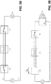
- Figure 1A illustrates the case in which the control module 10 and the power supply restoration module 20 are provided as two different modules.
- the control module 10 may comprise a first, electronically controlled switch 11 and the power supply restoration module 20 may comprise a second electronically controlled switch 21.
- electronically controlled switch is meant a switch in an electrical circuit which is controlled by electronics, such as for example which is controlled as a result of an "event" in the circuit, e.g. switching another switch in the circuit.
- a control circuit 13 is provided which, according to illustrated embodiment in figure 1A , comprises a first part or circuit 12 that is provided in the control module 10 and a second part or circuit 22 that is provided in the power supply restoration module 20.
- control module 10 and the power supply restoration module 20 are implemented in one and the same module, namely the control-restoration module 110.
- control module 10 may comprise a first, electronically controlled switch 11 and the power supply restoration module 20 may comprise a second, electronically controlled switch 21.
- the control circuit 13 does not comprise parts that are part of the control module 10 and the power supply restoration module 20 itself, as was the case in the embodiment illustrated in figure 1A , but is formed as a separate part, i.e. as a part different from the control module 10 and the power supply restoration module 20.
- Figures 2A and 2B illustrate examples of an electrical installation to which the present invention can be applied.
- Such an electrical installation may comprise at least one user-operated switch 50, 51, 52 and an electrical load 30, such as for example a lighting element, a heating element, a ventilation element, a roller blind, etc.
- the invention can be applied to any electrical installation, as soon as this electrical installation comprises one user-operated switch and an electrical load.
- Figure 2A illustrates such a minimalistic electrical installation which comprises one user-operated switch 50 and an electrical load, in this case, a lamp 30.
- the electrical installation comprises a set of power supply lines 41, 43 for providing power supply to the lamp 30.
- the electrical installation can be more extended than the one illustrated in figure 2A and can, for example, comprise a plurality of user-operated switches 50, 51, 52 and/or a plurality of electrical loads 30.
- Figure 2B illustrates an example hereof.
- the electrical installation comprises three user-operated switches 50, 51, 52 and an electrical load, also a lamp 30 in this example.
- the user-operated switches 50, 51, 52 can be implemented as alternating switches and/or as crossbar switches.
- a control module 10 When it is necessary to add extra "smart" functionality to the electrical load, in the present examples of figure 2A and 2B where the electrical load is a lamp 30 for example a dim functionality, according to the invention a control module 10 will be provided to add this functionality to the lamp 30. As is schematically illustrated in figures 3A and 3B , this control module 10 is positioned at the location of the lamp 30. To make sure that, in the event of a power interruption in one of the power supply lines 41, 43, the control module 10 is further provided with power supply, according to the invention, also a power supply restoration module 20 is provided. This power supply restoration module 20 is positioned at the location of one of the user-operated switches 50, 51 or 52 present in the electrical installation, in the example give at the location of user-operated switch 50.
- An important advantage of an assembly according to embodiments of the invention is that no communication is required between the control module 10 and the power supply restoration module 20.
- the control module 10 and the power supply restoration module 20 operate independent or substantially independent from each other.
- An assembly according to embodiments of the invention is especially beneficial for retrofit solutions.
- retrofit solutions is meant, the adjustment or upgrading of existing electrical installations in an existing home.
- a person skilled in the art will understand that the use of the invention is not limited to such existing installations but that an assembly according to embodiments of the invention can be used as well for new electrical installations and thus for newly constructed homes.
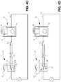
- FIGS 4A-4D illustrate the principle of the invention by means of a schematically illustrated embodiment of an electrical installation with a set of power supply lines 41, 43 for providing power supply to an electrical load 30, for example, a lamp.
- a set of power supply lines 41, 43 for providing power supply to an electrical load 30, for example, a lamp.
- three user-operated switches 50, 51, 52 are provided for turning the lamp 30 "on” and "off'.
- These user-operated switches 50, 51, 52 can be implemented as crossbar switches, alternating switches or a combination thereof.
- the electrical installation does not have to comprise exactly three user-operated switches but can comprise as many user-operated switches as required.
- a control module 10 is provided in which so-called “smart" functionalities are incorporated.
- control module 10 can be adapted to check the energy consumption and/or to carry out measurements of the energy consumption and/or to communicate wireless so as to regulate operation of the electrical load 30 from a distance, to provide the electrical load 30 with a dim function and/or any other functionality which may be assigned to an electrical load 30 as known by a person skilled in the art.
- control module 10 and the electrical load 30 are provided with power via the power supply lines 41, 43.
- a first switch 11 and a first circuit 12 are incorporated in the control module 10, and a power supply restoration module 20 comprising a second switch 21 and a second circuit 22 which is adapted for controlling the second switch 21 is provided in the set of power supply lines 41, 43.
- the first switch 11 is positioned downstream of a branch point A for providing power supply to the control module 10, between the electrical load 30 and the branch point A.
- the first and second switches 11, 21 are added respectively to the control module 10 and the power supply restoration module 20, and are typically electronically controlled switches.
- the second switch 21 is positioned in the set of power supply lines 41, 43 upstream from branch point A.
- the second switch 21 is provided in the set of power supply lines 41, 43 at another side of branch point A than the first switch 11.
- the control module 10 and the power supply restoration module 20 are implemented as two separate modules and they are positioned at a certain distance from each other in the electrical installation.
- the assembly furthermore comprises a control circuit.
- the control circuit comprises, according to the present embodiment, a first circuit 12 and a second circuit 22 which are adapted for detecting a power supply interruption in the set of power supply lines 41, 43 and which are positioned respectively in the control module 10 and in the power supply restoration module 20.
- control circuit comprises a first part or first circuit 12 that is part of the control module 10 and a second part or second circuit 22 that is part of the power supply restoration module 20. Furthermore, the first circuit 12 and the second circuit 22 are adapted to, upon detecting a power supply interruption, first switch the first switch 11 and subsequently switch the second switch 21.
- a small power buffer (not shown) may be provided in the control module 10. This power buffer may serve to bridge very short periods of time. For similar reasons a small power buffer (not shown either) may be provided in the power supply restoration module 20.
- the power supply restoration module 20 may preferably be adapted to co-operate with one of the user-operated switches 50, 51, 52 for producing a switching operation of the second switch 21 when operating one of these user-operated switches 50, 51, 52.
- the power supply restoration module 20 can be simply incorporated at the location of one of these user-operated switches 50, 51, 52.
- These user-operated switches 50, 51, 52 can for example be a part of an existing electrical installation.
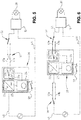
- FIG. 5 illustrates in greater detail a possible embodiment of a power supply restoration module 20 that is provided in a set of power supply lines 41, 41a, 41b, 43 in which furthermore user-operated switches 50, 51, 52 are provided.
- the control module 10 will not be discussed any more in detail since a person skilled in the art understands that it can be implemented as discussed in the earlier embodiment described above.
- the power supply restoration module 20 may be positioned at the location of a user-operated switch 50.
- the power supply restoration module 20 comprises a second, electronically controlled switch 21 and a second circuit 22.
- the second circuit 22 comprises a power supply interruption-detection circuit 23, in which typically an AC/DC converter may be provided, and a control 24.
- the control 24 is adapted to switch the second electronically controlled switch 21 when the power supply interruption-detection circuit 23 has detected a power supply interruption.
- the second switch 21 is added in the power supply lines 41, 41a, 41b.
- the second switch 21 has two outputs 21b, 21c which are respectively connected with wires 41a, 41b which run towards a user-operated switch 51.
- Input 21a of the second switch 21 is connected to the incoming wire 41 with insertion of the power supply interruption-detection circuit 23, or in other words, the power supply interruption-detection circuit 23 is located in between the incoming wire 41 and the input 21a of the second switch.
- the power supply interruption-detection circuit 23 detects a power supply interruption and the second switch 21 is switched after a first switch in the control module 10 has been switched as was described for the embodiment of figures 4A-4D .
- Figure 6 illustrates another embodiment of the power supply restoration module 20 in which the power supply restoration module 20 is provided between a first user-operated switch 50 and a second user-operated switch 52, and at the location of a third user-operated switch 51.
- the power supply restoration module 20 is similar to the power supply restoration module in the embodiment of figure 5 , but is now incorporated in a different way in the set of power supply lines 41, 41a, 41b, 43.
- the incoming power supply wires 41a, 41b are both connected to the power supply interrupt-detection circuit 23, and the outputs 21b, 21c of the second switch 21 are respectively connected to the output wires 41a, 41b.
- switch 50 When switch 50 is switched, there will be a power supply interruption for a short period of time that will be detected by the power supply interruption-detection circuit 23, because of which first the first switch 11 in the control module 10 will switch, after which the second switch 21 is switched by the control 24. Also here is thus taken care of restoring the power supply to the control module 10 at the time that one of the switches 50, 51, 52 is switched.
- FIG. 7 illustrates yet another embodiment of a power supply restoration module 20.
- the power supply restoration module 20 is provided in between a user-operated switch 51 and the control module 10, and at the location of a user-operated switch 52.
- the power supply interruption-detection circuit 23 is located downstream from the second switch 21. Further, two inputs 21b, 21c of the second switch 21 are respectively connected to power supply wires 41a, 41b which lead to switch 51.
- the output 21a of the second switch 21 is, with insertion of the power supply interruption-detection circuit 23 connected to an input of the control module 10, or in other words, the power supply interruption-detection circuit 23 is located in between the output 21a of the second switch 21 and the input of the control module 10.
- a power supply interruption as a result of switching one of switches 50, 51, 52 will be detected by the power supply interruption-detection circuit 23, whereby, after switching the first switch 11 in the control module 10, the second switch 21 is switched by the control 24.
- FIG 8 illustrates a further embodiment of an assembly according to the invention whereby the control module 10 and the power supply restoration module 20 are provided in one and the same module, hereinafter referred to as control-restoration module 110.
- the control-restoration module 110 may comprise a control module 10 comprising a first, electronically controlled switch 11 and a power supply restoration module 20 comprising a second, electronically controlled switch 21.
- the first switch 11 is provided in a power supply line running to the electrical load 30, downstream of a branch point A for providing power supply to the control module 10, between the electrical load 30 and the branch point A.
- the second switch 21 is provided in the set of power supply lines 41, 43 upstream of the branch point A and thus at the other side of branch point A than the first switch 11.
- the second switch 21 is adapted to switch between a first power supply wire 41a and a second power supply wire 41b.
- these power supply wires 41a, 41b run to a user-operated switch 51 which is intended to serve the electrical load 30.
- a control circuit 13 is further provided which comprises a power supply interruption-detection circuit 23 and a control 24.
- a signal is transmitted to the control 24 which in turn controls the second switch 21 and the first switch 11.
- This control is such that the first switch 11 is switched first, after which the second switch 21 is switched. In this way it is made sure that a power supply interruption at the location of the branch point A is only short in duration when operating one of the switches 50, 51.
Landscapes
- Engineering & Computer Science (AREA)
- Business, Economics & Management (AREA)
- Emergency Management (AREA)
- Power Engineering (AREA)
- Computer Networks & Wireless Communication (AREA)
- Circuit Arrangement For Electric Light Sources In General (AREA)
- Remote Monitoring And Control Of Power-Distribution Networks (AREA)
Priority Applications (1)
| Application Number | Priority Date | Filing Date | Title |
|---|---|---|---|
| PL15160224T PL2928045T3 (pl) | 2014-04-01 | 2015-03-23 | Zespół do dodawania funkcjonalności do obciążenia elektrycznego, moduł przywracania zasilania i moduł sterowania do stosowania w takim zespole, i instalacja elektryczna zawierająca taki zespół |
Applications Claiming Priority (1)
| Application Number | Priority Date | Filing Date | Title |
|---|---|---|---|
| BE2014/0225A BE1021815B1 (nl) | 2014-04-01 | 2014-04-01 | Samenstel voor toevoegen van functionaliteit aan een elektrische belasting in een elektrische installatie, voedingsherstelmodule en controlemodule voor gebruik in een dergelijk samenstel, en een systeem omvattende een dergelijk samenstel |
Publications (2)
| Publication Number | Publication Date |
|---|---|
| EP2928045A1 EP2928045A1 (en) | 2015-10-07 |
| EP2928045B1 true EP2928045B1 (en) | 2019-08-07 |
Family
ID=50884181
Family Applications (1)
| Application Number | Title | Priority Date | Filing Date |
|---|---|---|---|
| EP15160224.0A Not-in-force EP2928045B1 (en) | 2014-04-01 | 2015-03-23 | Assembly for adding functionality to an electrical load in an electrical installation, power supply restoration module and control module for use in such an assembly, and an electrical installation comprising such an assembly |
Country Status (5)
| Country | Link |
|---|---|
| EP (1) | EP2928045B1 (da) |
| BE (1) | BE1021815B1 (da) |
| DK (1) | DK2928045T3 (da) |
| HU (1) | HUE049581T2 (da) |
| PL (1) | PL2928045T3 (da) |
Families Citing this family (1)
| Publication number | Priority date | Publication date | Assignee | Title |
|---|---|---|---|---|
| WO2018095892A1 (en) * | 2016-11-28 | 2018-05-31 | Philips Lighting Holding B.V. | Controlling the power consumed by a communications module |
Family Cites Families (1)
| Publication number | Priority date | Publication date | Assignee | Title |
|---|---|---|---|---|
| US7847440B2 (en) * | 2005-06-06 | 2010-12-07 | Lutron Electronics Co., Inc. | Load control device for use with lighting circuits having three-way switches |
-
2014
- 2014-04-01 BE BE2014/0225A patent/BE1021815B1/nl not_active IP Right Cessation
-
2015
- 2015-03-23 HU HUE15160224A patent/HUE049581T2/hu unknown
- 2015-03-23 PL PL15160224T patent/PL2928045T3/pl unknown
- 2015-03-23 DK DK15160224.0T patent/DK2928045T3/da active
- 2015-03-23 EP EP15160224.0A patent/EP2928045B1/en not_active Not-in-force
Non-Patent Citations (1)
| Title |
|---|
| None * |
Also Published As
| Publication number | Publication date |
|---|---|
| BE1021815B1 (nl) | 2016-01-19 |
| PL2928045T3 (pl) | 2019-12-31 |
| DK2928045T3 (da) | 2019-09-30 |
| EP2928045A1 (en) | 2015-10-07 |
| HUE049581T2 (hu) | 2020-10-28 |
Similar Documents
| Publication | Publication Date | Title |
|---|---|---|
| CN109309991B (zh) | 一种控制方法、控制装置及控制系统 | |
| US9949338B2 (en) | Device to allow a two-way switch to operate in a multiple-switch electrical circuit | |
| CN105282914B (zh) | 开关设备以及包括该开关设备的负载控制系统 | |
| CN107798837A (zh) | 具有辅电力单元及无线接收功能的开关装置及其灯具系统 | |
| EP3660406B1 (en) | Air conditioner | |
| EP3381242B1 (en) | A lighting apparatus control switch and method | |
| CN113261172A (zh) | 用于监视被耦合至功率开关的负载的功耗的方法 | |
| EP2928045B1 (en) | Assembly for adding functionality to an electrical load in an electrical installation, power supply restoration module and control module for use in such an assembly, and an electrical installation comprising such an assembly | |
| CN104284489A (zh) | 照明控制装置及其控制方法 | |
| CN205160866U (zh) | 一种带人体感应及光照度探测的无线智能面板开关 | |
| US20160336797A1 (en) | Systems and methods for managing power sources for a plurality of luminaires | |
| CN203387730U (zh) | 智能照明系统 | |
| JP2013101136A (ja) | 過電流検出装置 | |
| EP2907151B1 (en) | Connector having wireless control capabilities | |
| CN102548133A (zh) | 用于控制电气负载的通信系统 | |
| US20120019066A1 (en) | Actuator and energy management system comprising such actuators | |
| CN108388143A (zh) | 一种带机械开关的智能面板开关及智能家居系统 | |
| CN103781258A (zh) | 调光电路及使用该调光电路的照明控制装置 | |
| CN112514538B (zh) | 负载控制系统 | |
| US11342833B2 (en) | Switch for a lighting system | |
| US11038507B2 (en) | Switch assembly and control method thereof | |
| KR20110032819A (ko) | 발열유리의 발열제어장치 | |
| CN106292826A (zh) | 一种单火线开关控制系统及控制方法 | |
| US11101654B2 (en) | System and method for determining master/slave switches in a multi-way switch system | |
| CN203775469U (zh) | 调光电路及使用该调光电路的照明控制装置 |
Legal Events
| Date | Code | Title | Description |
|---|---|---|---|
| PUAI | Public reference made under article 153(3) epc to a published international application that has entered the european phase |
Free format text: ORIGINAL CODE: 0009012 |
|
| AK | Designated contracting states |
Kind code of ref document: A1 Designated state(s): AL AT BE BG CH CY CZ DE DK EE ES FI FR GB GR HR HU IE IS IT LI LT LU LV MC MK MT NL NO PL PT RO RS SE SI SK SM TR |
|
| AX | Request for extension of the european patent |
Extension state: BA ME |
|
| 17P | Request for examination filed |
Effective date: 20160404 |
|
| RBV | Designated contracting states (corrected) |
Designated state(s): AL AT BE BG CH CY CZ DE DK EE ES FI FR GB GR HR HU IE IS IT LI LT LU LV MC MK MT NL NO PL PT RO RS SE SI SK SM TR |
|
| STAA | Information on the status of an ep patent application or granted ep patent |
Free format text: STATUS: EXAMINATION IS IN PROGRESS |
|
| 17Q | First examination report despatched |
Effective date: 20170720 |
|
| GRAP | Despatch of communication of intention to grant a patent |
Free format text: ORIGINAL CODE: EPIDOSNIGR1 |
|
| STAA | Information on the status of an ep patent application or granted ep patent |
Free format text: STATUS: GRANT OF PATENT IS INTENDED |
|
| INTG | Intention to grant announced |
Effective date: 20190228 |
|
| GRAS | Grant fee paid |
Free format text: ORIGINAL CODE: EPIDOSNIGR3 |
|
| GRAA | (expected) grant |
Free format text: ORIGINAL CODE: 0009210 |
|
| STAA | Information on the status of an ep patent application or granted ep patent |
Free format text: STATUS: THE PATENT HAS BEEN GRANTED |
|
| AK | Designated contracting states |
Kind code of ref document: B1 Designated state(s): AL AT BE BG CH CY CZ DE DK EE ES FI FR GB GR HR HU IE IS IT LI LT LU LV MC MK MT NL NO PL PT RO RS SE SI SK SM TR |
|
| REG | Reference to a national code |
Ref country code: GB Ref legal event code: FG4D |
|
| REG | Reference to a national code |
Ref country code: CH Ref legal event code: EP Ref country code: AT Ref legal event code: REF Ref document number: 1165307 Country of ref document: AT Kind code of ref document: T Effective date: 20190815 |
|
| REG | Reference to a national code |
Ref country code: DE Ref legal event code: R096 Ref document number: 602015035087 Country of ref document: DE |
|
| REG | Reference to a national code |
Ref country code: IE Ref legal event code: FG4D |
|
| REG | Reference to a national code |
Ref country code: CH Ref legal event code: NV Representative=s name: TR-IP CONSULTING LLC, CH |
|
| REG | Reference to a national code |
Ref country code: NL Ref legal event code: FP |
|
| REG | Reference to a national code |
Ref country code: DK Ref legal event code: T3 Effective date: 20190927 |
|
| REG | Reference to a national code |
Ref country code: SE Ref legal event code: TRGR |
|
| REG | Reference to a national code |
Ref country code: NO Ref legal event code: T2 Effective date: 20190807 |
|
| REG | Reference to a national code |
Ref country code: SK Ref legal event code: T3 Ref document number: E 32130 Country of ref document: SK |
|
| REG | Reference to a national code |
Ref country code: LT Ref legal event code: MG4D |
|
| PG25 | Lapsed in a contracting state [announced via postgrant information from national office to epo] |
Ref country code: PT Free format text: LAPSE BECAUSE OF FAILURE TO SUBMIT A TRANSLATION OF THE DESCRIPTION OR TO PAY THE FEE WITHIN THE PRESCRIBED TIME-LIMIT Effective date: 20191209 Ref country code: BG Free format text: LAPSE BECAUSE OF FAILURE TO SUBMIT A TRANSLATION OF THE DESCRIPTION OR TO PAY THE FEE WITHIN THE PRESCRIBED TIME-LIMIT Effective date: 20191107 Ref country code: FI Free format text: LAPSE BECAUSE OF FAILURE TO SUBMIT A TRANSLATION OF THE DESCRIPTION OR TO PAY THE FEE WITHIN THE PRESCRIBED TIME-LIMIT Effective date: 20190807 Ref country code: HR Free format text: LAPSE BECAUSE OF FAILURE TO SUBMIT A TRANSLATION OF THE DESCRIPTION OR TO PAY THE FEE WITHIN THE PRESCRIBED TIME-LIMIT Effective date: 20190807 Ref country code: LT Free format text: LAPSE BECAUSE OF FAILURE TO SUBMIT A TRANSLATION OF THE DESCRIPTION OR TO PAY THE FEE WITHIN THE PRESCRIBED TIME-LIMIT Effective date: 20190807 |
|
| REG | Reference to a national code |
Ref country code: CH Ref legal event code: PCAR Free format text: NEW ADDRESS: ROUTE DU COUTSET 18, 1485 NUVILLY (CH) |
|
| REG | Reference to a national code |
Ref country code: AT Ref legal event code: MK05 Ref document number: 1165307 Country of ref document: AT Kind code of ref document: T Effective date: 20190807 |
|
| PG25 | Lapsed in a contracting state [announced via postgrant information from national office to epo] |
Ref country code: ES Free format text: LAPSE BECAUSE OF FAILURE TO SUBMIT A TRANSLATION OF THE DESCRIPTION OR TO PAY THE FEE WITHIN THE PRESCRIBED TIME-LIMIT Effective date: 20190807 Ref country code: AL Free format text: LAPSE BECAUSE OF FAILURE TO SUBMIT A TRANSLATION OF THE DESCRIPTION OR TO PAY THE FEE WITHIN THE PRESCRIBED TIME-LIMIT Effective date: 20190807 Ref country code: GR Free format text: LAPSE BECAUSE OF FAILURE TO SUBMIT A TRANSLATION OF THE DESCRIPTION OR TO PAY THE FEE WITHIN THE PRESCRIBED TIME-LIMIT Effective date: 20191108 Ref country code: RS Free format text: LAPSE BECAUSE OF FAILURE TO SUBMIT A TRANSLATION OF THE DESCRIPTION OR TO PAY THE FEE WITHIN THE PRESCRIBED TIME-LIMIT Effective date: 20190807 Ref country code: LV Free format text: LAPSE BECAUSE OF FAILURE TO SUBMIT A TRANSLATION OF THE DESCRIPTION OR TO PAY THE FEE WITHIN THE PRESCRIBED TIME-LIMIT Effective date: 20190807 Ref country code: IS Free format text: LAPSE BECAUSE OF FAILURE TO SUBMIT A TRANSLATION OF THE DESCRIPTION OR TO PAY THE FEE WITHIN THE PRESCRIBED TIME-LIMIT Effective date: 20191207 |
|
| PG25 | Lapsed in a contracting state [announced via postgrant information from national office to epo] |
Ref country code: TR Free format text: LAPSE BECAUSE OF FAILURE TO SUBMIT A TRANSLATION OF THE DESCRIPTION OR TO PAY THE FEE WITHIN THE PRESCRIBED TIME-LIMIT Effective date: 20190807 |
|
| PG25 | Lapsed in a contracting state [announced via postgrant information from national office to epo] |
Ref country code: IT Free format text: LAPSE BECAUSE OF FAILURE TO SUBMIT A TRANSLATION OF THE DESCRIPTION OR TO PAY THE FEE WITHIN THE PRESCRIBED TIME-LIMIT Effective date: 20190807 Ref country code: RO Free format text: LAPSE BECAUSE OF FAILURE TO SUBMIT A TRANSLATION OF THE DESCRIPTION OR TO PAY THE FEE WITHIN THE PRESCRIBED TIME-LIMIT Effective date: 20190807 Ref country code: AT Free format text: LAPSE BECAUSE OF FAILURE TO SUBMIT A TRANSLATION OF THE DESCRIPTION OR TO PAY THE FEE WITHIN THE PRESCRIBED TIME-LIMIT Effective date: 20190807 Ref country code: EE Free format text: LAPSE BECAUSE OF FAILURE TO SUBMIT A TRANSLATION OF THE DESCRIPTION OR TO PAY THE FEE WITHIN THE PRESCRIBED TIME-LIMIT Effective date: 20190807 |
|
| PG25 | Lapsed in a contracting state [announced via postgrant information from national office to epo] |
Ref country code: IS Free format text: LAPSE BECAUSE OF FAILURE TO SUBMIT A TRANSLATION OF THE DESCRIPTION OR TO PAY THE FEE WITHIN THE PRESCRIBED TIME-LIMIT Effective date: 20200224 Ref country code: SM Free format text: LAPSE BECAUSE OF FAILURE TO SUBMIT A TRANSLATION OF THE DESCRIPTION OR TO PAY THE FEE WITHIN THE PRESCRIBED TIME-LIMIT Effective date: 20190807 |
|
| REG | Reference to a national code |
Ref country code: DE Ref legal event code: R097 Ref document number: 602015035087 Country of ref document: DE |
|
| PLBE | No opposition filed within time limit |
Free format text: ORIGINAL CODE: 0009261 |
|
| STAA | Information on the status of an ep patent application or granted ep patent |
Free format text: STATUS: NO OPPOSITION FILED WITHIN TIME LIMIT |
|
| PG2D | Information on lapse in contracting state deleted |
Ref country code: IS |
|
| 26N | No opposition filed |
Effective date: 20200603 |
|
| PG25 | Lapsed in a contracting state [announced via postgrant information from national office to epo] |
Ref country code: SI Free format text: LAPSE BECAUSE OF FAILURE TO SUBMIT A TRANSLATION OF THE DESCRIPTION OR TO PAY THE FEE WITHIN THE PRESCRIBED TIME-LIMIT Effective date: 20190807 |
|
| REG | Reference to a national code |
Ref country code: HU Ref legal event code: AG4A Ref document number: E049581 Country of ref document: HU |
|
| PG25 | Lapsed in a contracting state [announced via postgrant information from national office to epo] |
Ref country code: MC Free format text: LAPSE BECAUSE OF FAILURE TO SUBMIT A TRANSLATION OF THE DESCRIPTION OR TO PAY THE FEE WITHIN THE PRESCRIBED TIME-LIMIT Effective date: 20190807 |
|
| PG25 | Lapsed in a contracting state [announced via postgrant information from national office to epo] |
Ref country code: LU Free format text: LAPSE BECAUSE OF NON-PAYMENT OF DUE FEES Effective date: 20200323 |
|
| PG25 | Lapsed in a contracting state [announced via postgrant information from national office to epo] |
Ref country code: IE Free format text: LAPSE BECAUSE OF NON-PAYMENT OF DUE FEES Effective date: 20200323 |
|
| PGFP | Annual fee paid to national office [announced via postgrant information from national office to epo] |
Ref country code: CZ Payment date: 20210323 Year of fee payment: 7 |
|
| PGFP | Annual fee paid to national office [announced via postgrant information from national office to epo] |
Ref country code: HU Payment date: 20210425 Year of fee payment: 7 |
|
| PGFP | Annual fee paid to national office [announced via postgrant information from national office to epo] |
Ref country code: GB Payment date: 20220321 Year of fee payment: 8 Ref country code: DK Payment date: 20220323 Year of fee payment: 8 Ref country code: CH Payment date: 20220321 Year of fee payment: 8 |
|
| PG25 | Lapsed in a contracting state [announced via postgrant information from national office to epo] |
Ref country code: MT Free format text: LAPSE BECAUSE OF FAILURE TO SUBMIT A TRANSLATION OF THE DESCRIPTION OR TO PAY THE FEE WITHIN THE PRESCRIBED TIME-LIMIT Effective date: 20190807 Ref country code: CY Free format text: LAPSE BECAUSE OF FAILURE TO SUBMIT A TRANSLATION OF THE DESCRIPTION OR TO PAY THE FEE WITHIN THE PRESCRIBED TIME-LIMIT Effective date: 20190807 |
|
| PGFP | Annual fee paid to national office [announced via postgrant information from national office to epo] |
Ref country code: SK Payment date: 20220322 Year of fee payment: 8 Ref country code: SE Payment date: 20220321 Year of fee payment: 8 Ref country code: NO Payment date: 20220323 Year of fee payment: 8 Ref country code: NL Payment date: 20220321 Year of fee payment: 8 Ref country code: FR Payment date: 20220322 Year of fee payment: 8 Ref country code: BE Payment date: 20220321 Year of fee payment: 8 |
|
| PG25 | Lapsed in a contracting state [announced via postgrant information from national office to epo] |
Ref country code: MK Free format text: LAPSE BECAUSE OF FAILURE TO SUBMIT A TRANSLATION OF THE DESCRIPTION OR TO PAY THE FEE WITHIN THE PRESCRIBED TIME-LIMIT Effective date: 20190807 |
|
| PG25 | Lapsed in a contracting state [announced via postgrant information from national office to epo] |
Ref country code: CZ Free format text: LAPSE BECAUSE OF NON-PAYMENT OF DUE FEES Effective date: 20220323 |
|
| PGFP | Annual fee paid to national office [announced via postgrant information from national office to epo] |
Ref country code: PL Payment date: 20220310 Year of fee payment: 8 |
|
| PG25 | Lapsed in a contracting state [announced via postgrant information from national office to epo] |
Ref country code: HU Free format text: LAPSE BECAUSE OF NON-PAYMENT OF DUE FEES Effective date: 20220324 |
|
| PGFP | Annual fee paid to national office [announced via postgrant information from national office to epo] |
Ref country code: DE Payment date: 20220620 Year of fee payment: 9 |
|
| REG | Reference to a national code |
Ref country code: NO Ref legal event code: MMEP |
|
| REG | Reference to a national code |
Ref country code: CH Ref legal event code: PL Ref country code: SE Ref legal event code: EUG |
|
| REG | Reference to a national code |
Ref country code: DK Ref legal event code: EBP Effective date: 20230331 |
|
| REG | Reference to a national code |
Ref country code: SK Ref legal event code: MM4A Ref document number: E 32130 Country of ref document: SK Effective date: 20230323 Ref country code: NL Ref legal event code: MM Effective date: 20230401 |
|
| GBPC | Gb: european patent ceased through non-payment of renewal fee |
Effective date: 20230323 |
|
| REG | Reference to a national code |
Ref country code: BE Ref legal event code: MM Effective date: 20230331 |
|
| PG25 | Lapsed in a contracting state [announced via postgrant information from national office to epo] |
Ref country code: NL Free format text: LAPSE BECAUSE OF NON-PAYMENT OF DUE FEES Effective date: 20230401 |
|
| PG25 | Lapsed in a contracting state [announced via postgrant information from national office to epo] |
Ref country code: SK Free format text: LAPSE BECAUSE OF NON-PAYMENT OF DUE FEES Effective date: 20230323 |
|
| PG25 | Lapsed in a contracting state [announced via postgrant information from national office to epo] |
Ref country code: GB Free format text: LAPSE BECAUSE OF NON-PAYMENT OF DUE FEES Effective date: 20230323 |
|
| PG25 | Lapsed in a contracting state [announced via postgrant information from national office to epo] |
Ref country code: SK Free format text: LAPSE BECAUSE OF NON-PAYMENT OF DUE FEES Effective date: 20230323 Ref country code: SE Free format text: LAPSE BECAUSE OF NON-PAYMENT OF DUE FEES Effective date: 20230324 Ref country code: NO Free format text: LAPSE BECAUSE OF NON-PAYMENT OF DUE FEES Effective date: 20230331 Ref country code: LI Free format text: LAPSE BECAUSE OF NON-PAYMENT OF DUE FEES Effective date: 20230331 Ref country code: GB Free format text: LAPSE BECAUSE OF NON-PAYMENT OF DUE FEES Effective date: 20230323 Ref country code: FR Free format text: LAPSE BECAUSE OF NON-PAYMENT OF DUE FEES Effective date: 20230331 Ref country code: CH Free format text: LAPSE BECAUSE OF NON-PAYMENT OF DUE FEES Effective date: 20230331 |
|
| PG25 | Lapsed in a contracting state [announced via postgrant information from national office to epo] |
Ref country code: BE Free format text: LAPSE BECAUSE OF NON-PAYMENT OF DUE FEES Effective date: 20230331 |
|
| PG25 | Lapsed in a contracting state [announced via postgrant information from national office to epo] |
Ref country code: DK Free format text: LAPSE BECAUSE OF NON-PAYMENT OF DUE FEES Effective date: 20230331 |
|
| PG25 | Lapsed in a contracting state [announced via postgrant information from national office to epo] |
Ref country code: PL Free format text: LAPSE BECAUSE OF NON-PAYMENT OF DUE FEES Effective date: 20230323 |
|
| PG25 | Lapsed in a contracting state [announced via postgrant information from national office to epo] |
Ref country code: PL Free format text: LAPSE BECAUSE OF NON-PAYMENT OF DUE FEES Effective date: 20230323 |
|
| REG | Reference to a national code |
Ref country code: DE Ref legal event code: R119 Ref document number: 602015035087 Country of ref document: DE |
|
| PG25 | Lapsed in a contracting state [announced via postgrant information from national office to epo] |
Ref country code: DE Free format text: LAPSE BECAUSE OF NON-PAYMENT OF DUE FEES Effective date: 20241001 |
|
| PG25 | Lapsed in a contracting state [announced via postgrant information from national office to epo] |
Ref country code: DE Free format text: LAPSE BECAUSE OF NON-PAYMENT OF DUE FEES Effective date: 20241001 |
|
| REG | Reference to a national code |
Ref country code: CH Ref legal event code: R17 Free format text: ST27 STATUS EVENT CODE: U-0-0-R10-R17 (AS PROVIDED BY THE NATIONAL OFFICE) Effective date: 20251029 |